Article

Characteristics Evaluation of a Segmental Rotor Type Switched Reluctance Motor with Concentrated Winding for Torque Density and Efficiency Improvement

1
School of Electrical Engineering, Shenyang University of Technology, Shenyang 110870, China
2
School of Instrumentation Science and Opto-Electronics Engineering, Beihang University, Beijing 100191, China
3
Department of Mechatronics Engineering, Kyungsung University, Busan 48434, Republic of Korea
*
Author to whom correspondence should be addressed.
Energies 2022, 15(23), 8915; https://doi.org/10.3390/en15238915
Submission received: 1 November 2022 / Revised: 17 November 2022 / Accepted: 23 November 2022 / Published: 25 November 2022
(This article belongs to the Special Issue Regulations and Advances in High Performance Electric Motor and Drive)

Abstract

:
With the rapid development of power electronic techniques and the increasing cost of permanent magnets (PMs) materials, switched reluctance motors (SRMs) have recently gained more attention. However, traditional SRMs have a relatively low torque density. For the sake of increasing the motor torque density, this paper proposes a novel segmental rotor type SRM. The proposed motor adopts hybrid stator poles and concentrated windings in the stator side and a segmental rotor structure in the rotor side, which is completely different from the structures of the traditional SRM. The special structure of the motor shortens the magnetic flux paths of the motor, separates the parts of the magnetic flux paths from one another, and eradicates the magnetic flux reversal in the motor stator in order to improve the electric utilization and output torque density of the motor. Meanwhile, the requirement of the magneto-motive force and the core loss of the motor is also decreased, thereby improving the efficiency of the motor. For the purpose of proving the proposed structure, the characteristics of the motor are analyzed using the finite element method and are compared to those of the traditional 12/8 SRM, which is designed for the same application. Moreover, the prototypes of the traditional 12/8 and proposed SRMs are manufactured, and experiments based on the prototypes are performed. Finally, the effectiveness of the structure of the proposed motor is further proven by the experimental results.

1. Introduction

For the past few years, with the rapid improvement of the design and manufacturing techniques of power electronics, the cost of the controller for the motor is falling, coupled with the rise of the cost of permanent magnets (PMs) materials. As a result, switched reluctance motors (SRMs) have attracted widespread attention due to their simple manufacturing process, good fault tolerance and lack of PMs, thus becoming strong candidates for the variable speed drive systems used in industrial applications.
Traditional SRMs tend to adopt a doubly salient pole and concentrated winding configuration, on account of their simple structure and short end-winding. Nevertheless, the torque density of traditional SRMs is relatively low.
For the purpose of increasing the torque density of SRMs, scholars around the world have studied the structure of SRM and proposed a segmental rotor structure [1,2,3,4,5,6,7,8,9,10,11,12,13,14,15]. Reference [1] proposes a 12/8 SRM with full pitch windings and a segmental rotor. With a fixed thermal condition, the torque per unit copper loss of the motor is increased by 41% in comparison with that of traditional SRMs under the same volume; however, the motor has problems of mechanical weakness and manufacturing complexity. In order to solve the problems of the motor in [1], a 6/4 SRM with full pitch windings and a segmental rotor is proposed [2]. The motor adopts an aluminum rotor block, thereby reducing the manufacturing complexity of the segmental rotor and improving its mechanical strength. Furthermore, the motor maintains the relatively high torque density as that of the motor in [1]. On the basis of the motor in [2], the motors with multiphases [3] and with a two-step slide-rotor [4] are studied, respectively, to further improve the torque performance of the SRM. At the same time, 8/6, 12/4 and circular slot type SRMs with full pitch windings and a segmental rotor are also presented [5,6,7] for torque performance improvement. For the 8/6 type [5], it is a four-phase motor, in which two adjacent phases are excited simultaneously at any given moment. The 8/6 type increases the output torque density of the motor and decreases the torque ripple of the motor, while it increases the cost of the converter compared to the three-phase motor. For the 12/4 type [6], it is a six-phase motor, whose rotor segments are unevenly installed on the rotor block, and two phase windings of the motor are always required to be energized at the same time. For the circular slot type [7], its magnetic flux flows along the circular path in the rotor and stator of the motor, shortening the flux path, thus improving the output torque density and decreasing the silicon steel sheet utilization.
In contrast to traditional SRMs, the segmental rotor type SRMs presented above could improve the electric utilization of the motor and reduce the requirements of magneto-motive force (MMF). The output torque could be increased as well. Nevertheless, all of the motors mentioned above use full pitch windings, which increase the length of the end-windings, thereby increasing the mass of copper material and copper losses, and at the same time, reducing the electric loading and fault tolerance of the motor. Furthermore, it also makes the motors unrealistic for applications with a short lamination stack length and large pole pitches because of its low efficiency.
Based on the above analysis, some scholars have proposed SRMs with concentrated windings and a segmental rotor, such as the 12/10 type [8,9,10], 12/8 type [11] and 16/10 type [12,13,14,15]. Compared to traditional SRMs, the SRMs with concentrated windings and a segmental rotor not only improves the electric utilization, torque output capacity and efficiency of the motor, but also reduces the requirement of MMF in the motor. However, the number of rotor poles in these motors is a little high, which may limit the efficiency of the motor. This is because the core losses of the motor are related to the electrical frequency of the motor. The higher the electrical frequency of the motor, the higher the core losses. Furthermore, with a given speed, the electrical frequency of an SRM is proportional to the number of rotor poles. Thus, to ensure the motor high efficiency, it is better to make the rotor pole number as low as possible.
With that in mind, this paper proposes a novel 6/5 SRM with concentrated windings and segmental rotor for torque density and efficiency improvement. Firstly, the traditional and proposed SRM structures are presented and analyzed. Then, the characteristics of the proposed structure are analyzed and contrasted with those of the traditional 12/8 SRM in the same application. Moreover, to further prove the proposed structure, the prototypes and control platform of the two motors are developed, respectively. Finally, the experiments based on the prototypes and developed control platform are performed to further prove the effectiveness of the proposed 6/5 SRM.

2. Structure of Traditional and Proposed SRMs

2.1. Structure of Traditional SRM

Figure 1 shows the diagram of the traditional 12/8 SRM structure. It has twelve stator poles and eight rotor poles. The twelve stator poles have the same size and shape, and the windings are wound on each stator pole. Among them, windings WA1, WA2, WA3 and WA4 are connected to form phase A; windings WB1, WB2, WB3 and WB4 are connected to form phase B; windings WC1, WC2, WC3 and WC4 are connected to form phase C. The rotor adopts a salient pole structure and the eight rotor poles, with the same size and shape, are evenly distributed along the circumference.
Figure 2 shows the magnetic field vector of the traditional 12/8 SRM. It can be seen that the magnetic flux paths of the motor are long, and when the motor winding current transitions from one phase to another phase, regardless of whether in forward or reverse rotation of the motor, there is a reverse flux in the motor stator. This may increase the requirement of MMF in the motor and increase the core loss of the motor.

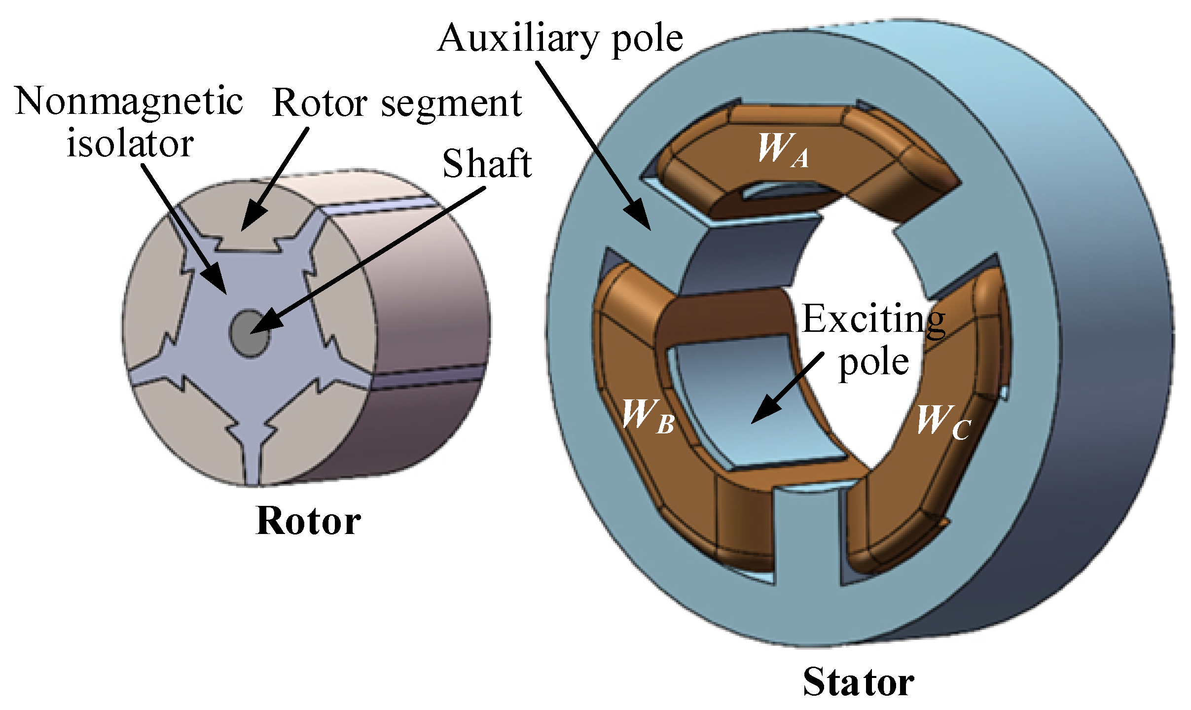
2.2. Structure of Proposed SRM

Figure 3 shows the diagram of the proposed 6/5 SRM structure. As the name suggests, this configuration has six stator poles and five rotor poles. The six stator poles are further decomposed into three auxiliary poles and three exciting poles. The exciting poles are wound with the windings, and each winding forms a separate phase. The auxiliary poles do not have any windings, they only provide the magnetic flux return paths for the motor. The rotor consists of five rotor segments, a nonmagnetic isolator and a shaft. The nonmagnetic isolator is directly mounted onto the surface of the shaft, and the five rotor segments are of the same size and shape, and they are evenly placed in the nonmagnetic isolator along the circumference. Compared to the traditional rotor with salient poles, the rotor of the proposed 6/5 SRM does not have any mechanical protrusion, which is beneficial to reducing wind resistance, thus reducing the mechanical loss of the motor, particularly in the motor running at high-speed.
Figure 4 shows the magnetic field vector of the proposed 6/5 SRM. It can be observed that the magnetic flux paths of the motor are short, and whether the motor is in forward rotation or reverse rotation, when the motor winding current transits from one phase to another, there is no magnetic flux reversal in the motor stator. Hence, in comparison with the traditional 12/8 SRM, the proposed 6/5 SRM could improve the electric utilization of the motor, increase the output torque density of the motor, lower the requirement of MMF of the motor, and decrease the core loss of the motor, thereby improving the efficiency of the motor.

3. Characteristics Analysis and Comparison of Traditional and Proposed SRMs

In order to prove the effectiveness of the proposed motor, the outer radius and stack length of the proposed motor is designed to be the same as those of the traditional 12/8 SRM as they are intended for the same application, in which the rated power, rated voltage and rated speed is 500 W, 12 V, and 2800 r/min, respectively. In addition, for precise comparison, the air-gap length, shaft radius, slot fill factor and wire gauge of the proposed 6/5 SRM is also deliberately designed to be the same as those of the traditional 12/8 SRM. Table 1 gives the detailed dimensions of the two motors. Compared to traditional 12/8 SRM, the number of turns of the windings per phase of the proposed 6/5 SRM is reduced by 30%.

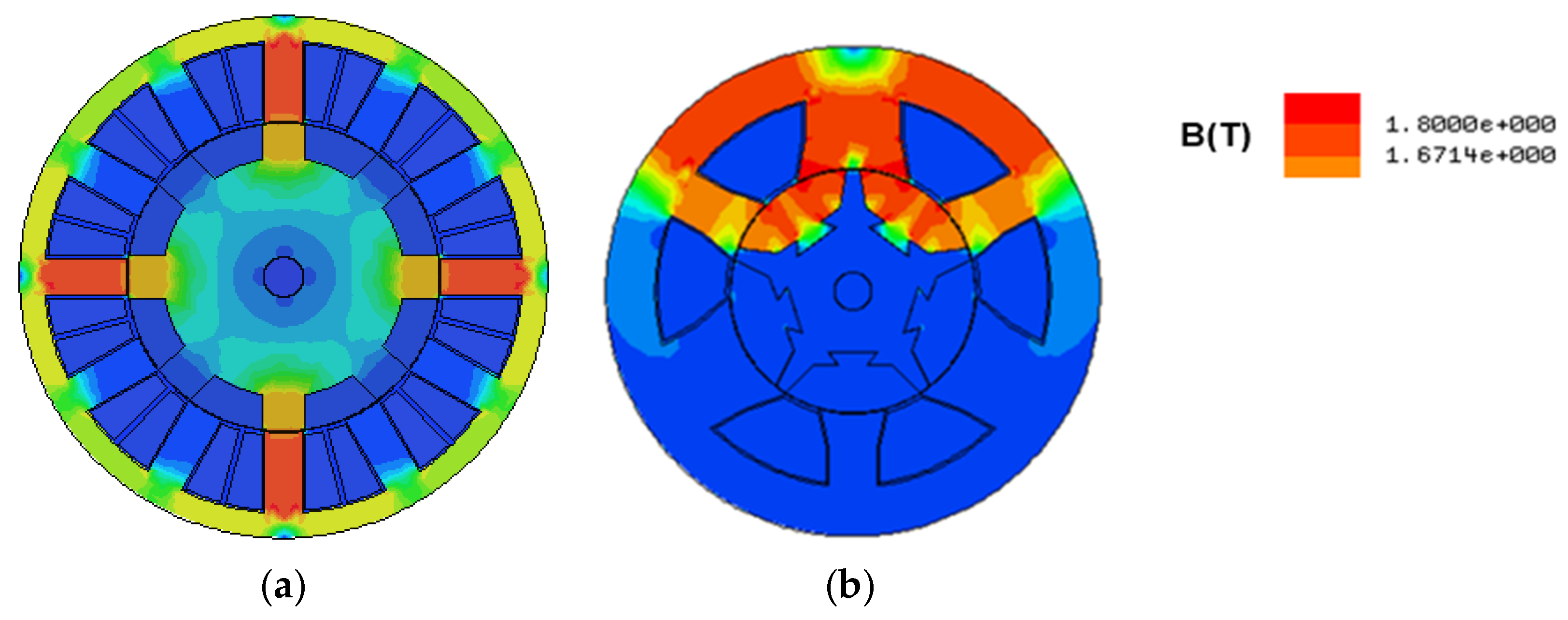
3.1. Magnetic Flux Density Comparison

In order to obtain maximum output torque, the magnetic flux density in an SRM should be designed to be as high as possible. Considering the actual magnetic properties of the silicon steel sheet material, the magnetic flux density in the machine should be designed as close as possible to 1.8 T, but it is better not to exceed 1.8 T. Figure 5 shows the magnetic flux density in the traditional 12/8 and the proposed 6/5 SRMs under a rated operating condition. It is apparent that the maximum magnetic flux density in the two motors is very close, and less than 1.8 T, which meets the design requirements.

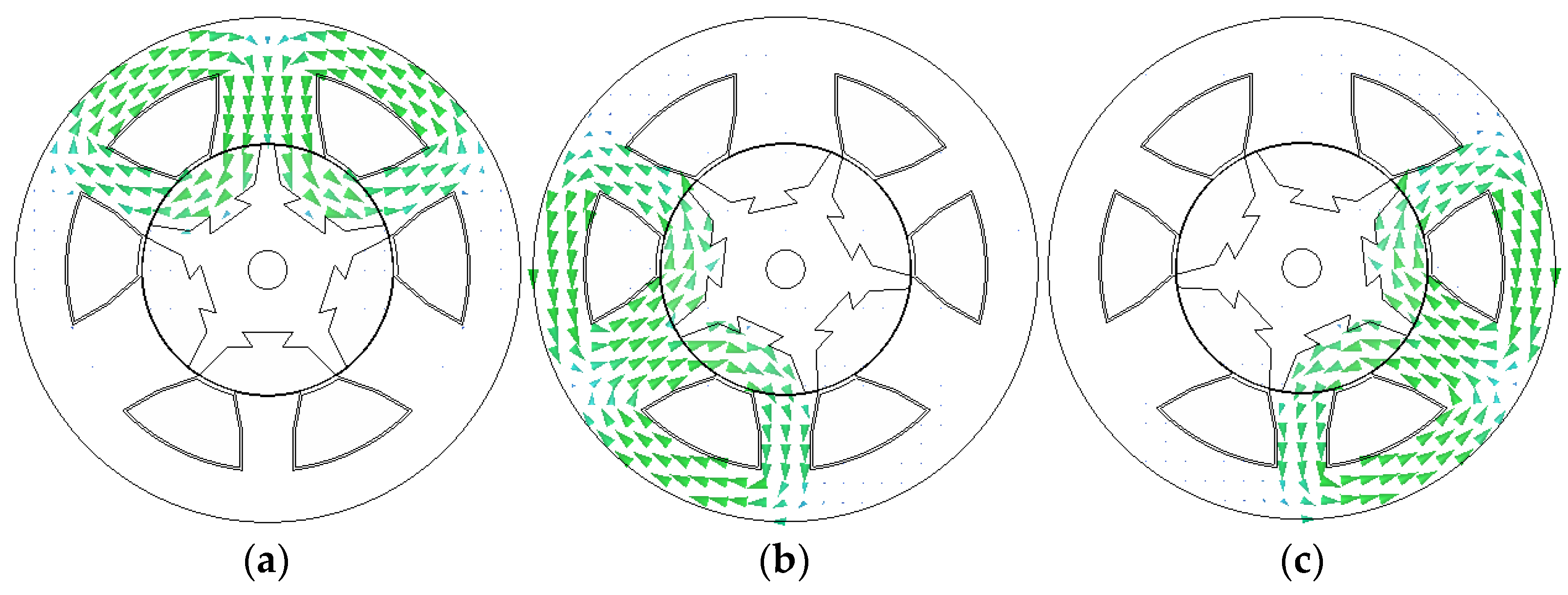
3.2. Inductance Comparison

Figure 6 shows the three-dimensional inductance curves of the traditional 12/8 and proposed 6/5 SRMs. In order to facilitate comparison, the electrical degree (edeg.) is used in the figures. Meanwhile, the maximum and minimum inductance comparison between the two motors is shown in Figure 7. It is evident that the maximum and minimum inductance of the proposed 6/5 SRM is higher than those of traditional 12/8 SRM at each current level. Moreover, with the increase in the current, the maximum inductance of the traditional 12/8 and proposed 6/5 SRMs decreases gradually, while the minimum inductance of the two motors remains essentially unchanged. This is a result of the core magnetic saturation of the motor. Moreover, when the current increases from 10 A to 110 A, the maximum inductance of the proposed 6/5 type decreases significantly faster than that of the traditional 12/8 type; therefore, it could be concluded that the proposed 6/5 type is more susceptible to saturation compared to the traditional 12/8 type.

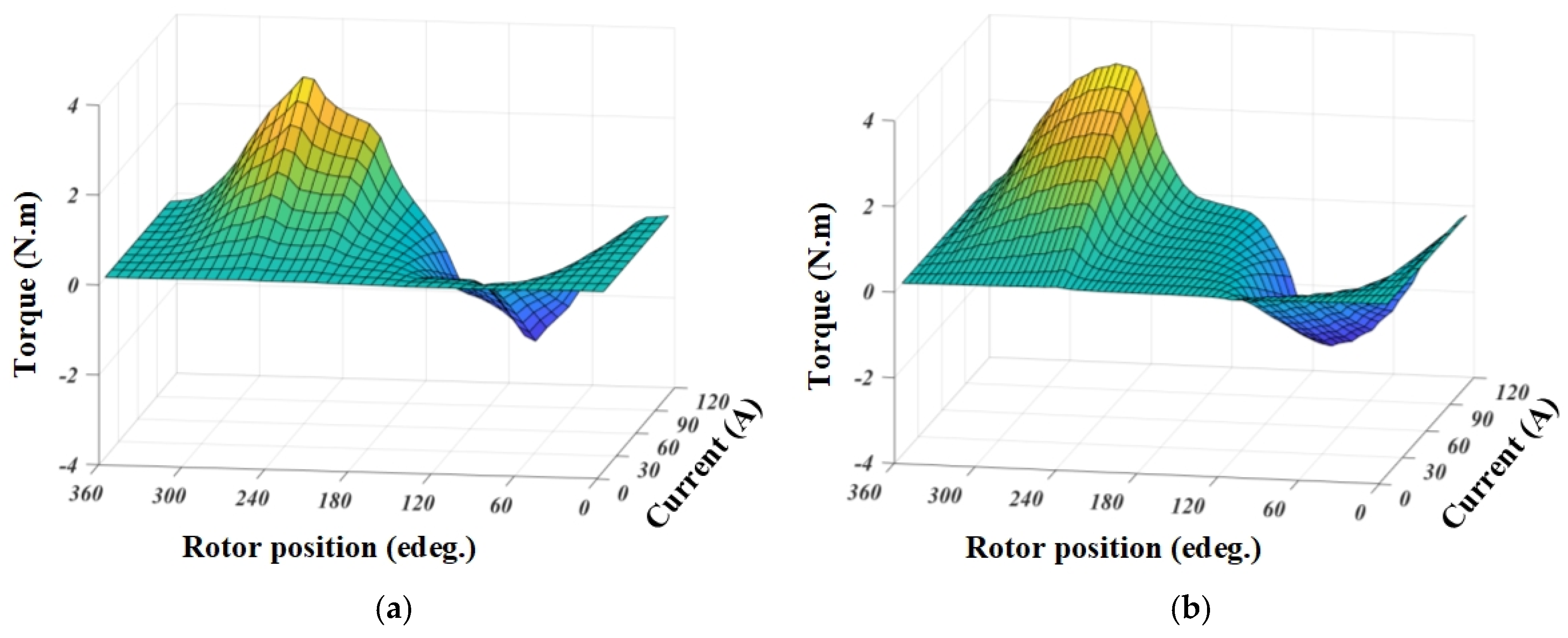
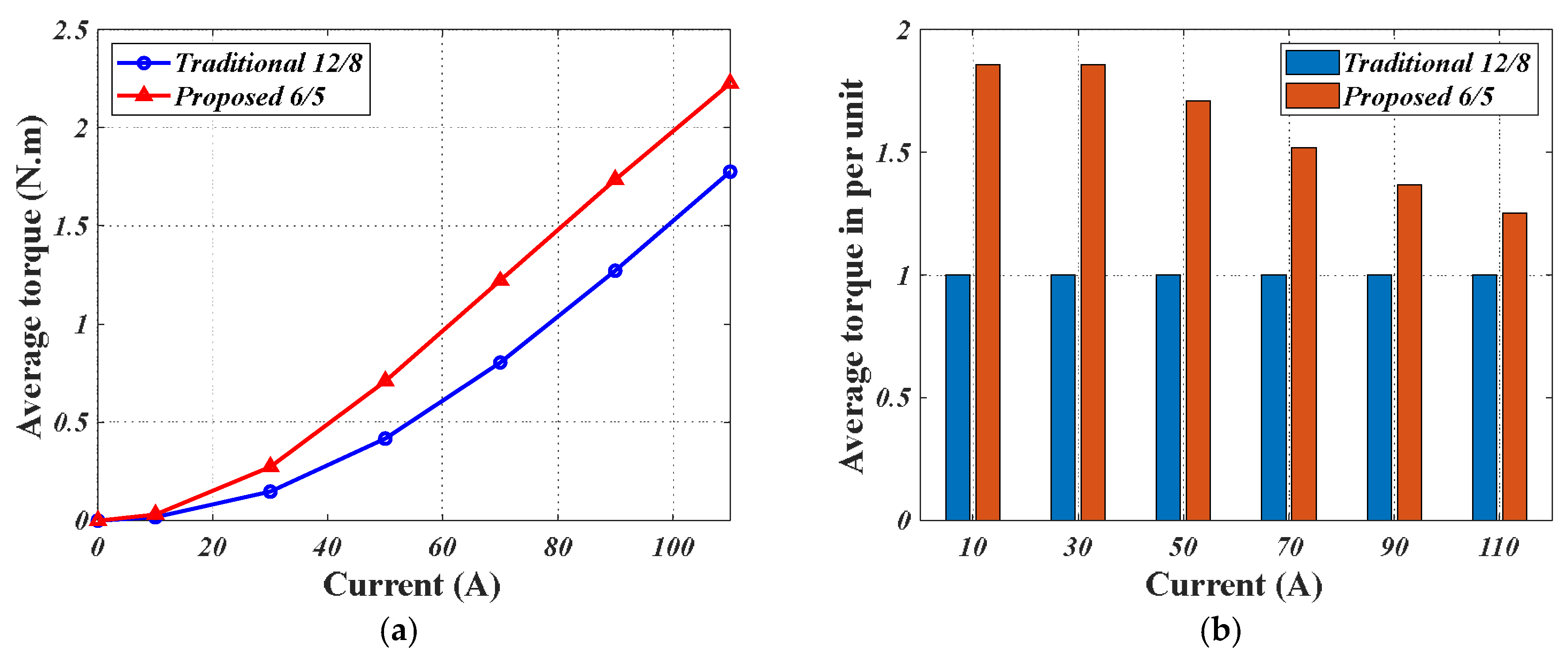
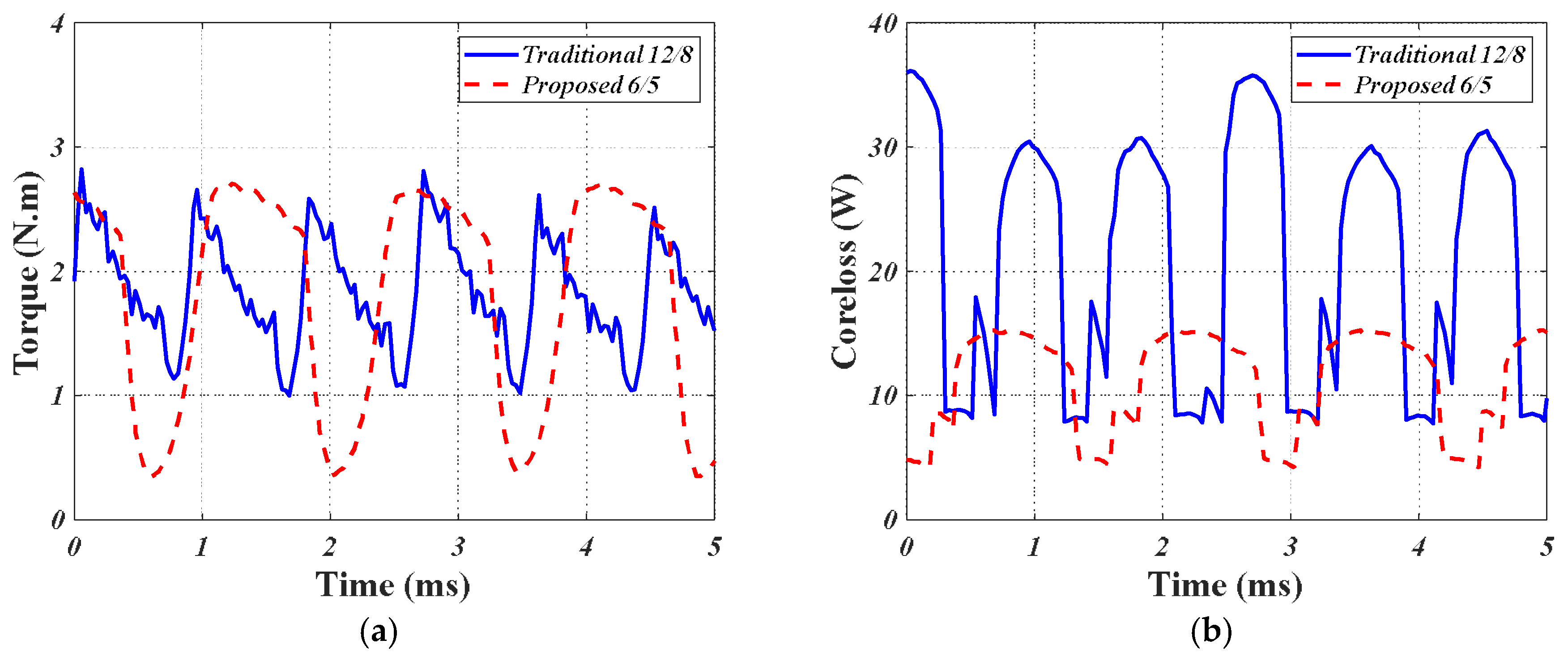
3.3. Torque Comparison

Figure 8 shows the three-dimensional torque curves of the traditional 12/8 and proposed 6/5 SRMs. Figure 9 gives the average torque of the two motors. Under the same current conditions, the average torque of the proposed 6/5 type is evidently larger than that of the traditional 12/8 type at each current level, and the increase advantage is maintained by at least 25%, as shown in Figure 9b. In addition, it is important to note that the results in Figure 9 are evaluated when the MMF of the proposed 6/5 type is 30% lower than that of the traditional 12/8 type. This verifies the effectiveness of the proposed 6/5 type.

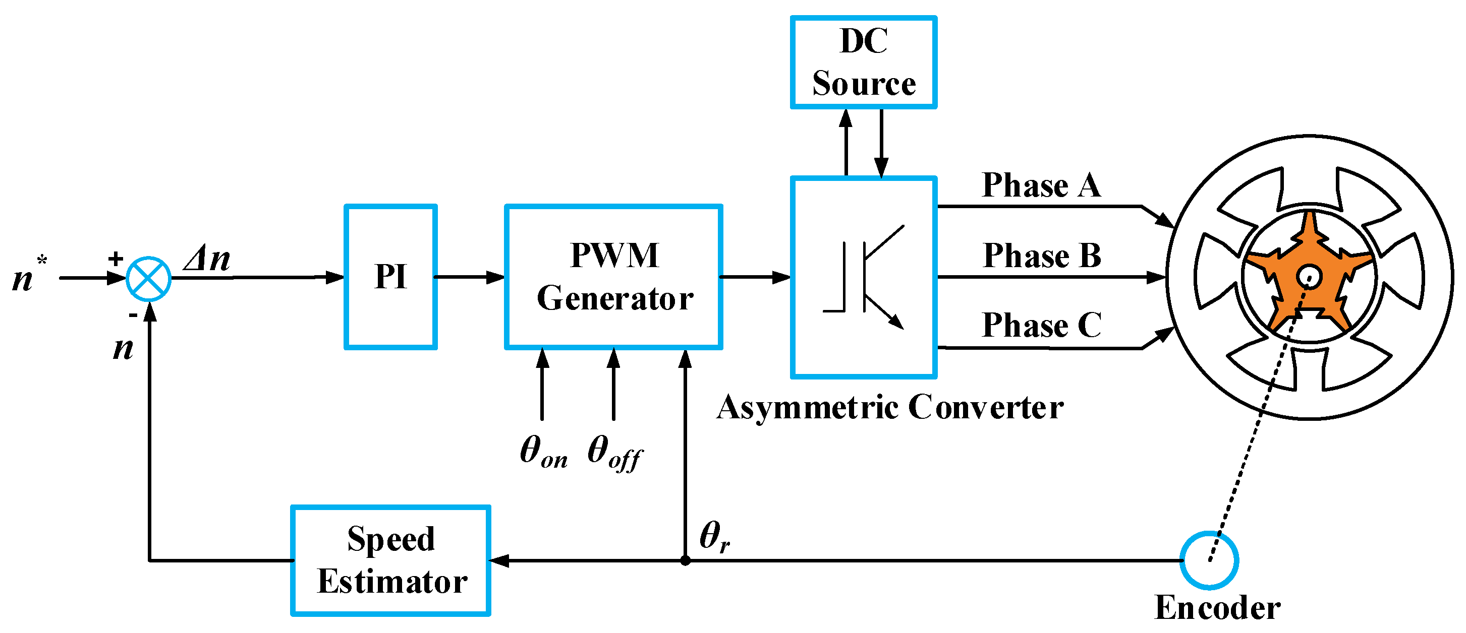
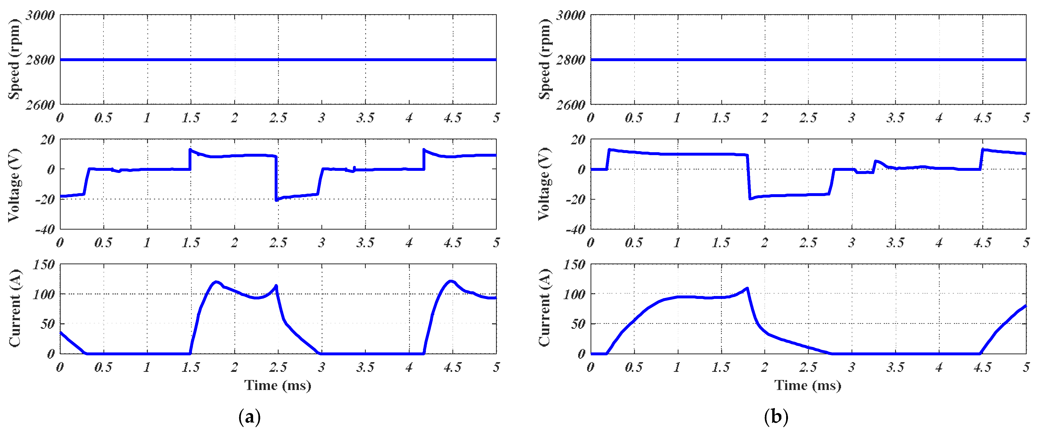
3.4. Steady-State Characteristics Comparison

In order to accurately obtain the steady-state characteristics of the two motors, an external circuit must be constructed and then combined with the finite element analysis (FEA) software for real-time calculation. Taking into consideration its many advantages, such as its capability of independent control for each phase and four switching modes, an asymmetric converter is adopted for controlling the two motors. Figure 10 shows the topology of the asymmetric converter for the two motors. Meanwhile, based on the asymmetric converter, a control scheme for the traditional 12/8 and proposed 6/5 SRMs is proposed in Figure 11. As is shown, the two motors would be controlled with speed control and without current control, this is because the application of the two motors has the characteristics of a low voltage and high current, in which there is not enough time to control the current.
Figure 12 shows the driving circuit constructed according to the control scheme and topology of the asymmetric converter for driving the two motors in the simulation. In the circuit, the asymmetric converter is made up of switches and diodes. The properties of the switches and diodes are setup by the Smodel1 and Dmodel1, respectively. The inductors, LPhaseA, LphaseB and LphaseC, represent the winding inductance of phase A, B and C, respectively. The values of the inductors could be adjusted in real-time using FEA software. In addition, for precise calculation, the leakage inductance of the end windings of each phase is also considered in the simulation.
Figure 13 shows the simulation results of the traditional 12/8 and proposed 6/5 SRMs under a rated operating condition. It can be seen from the figures that the currents in both of the motors have a slight spike near the end of each conduction interval. The slight spike could be weakened or eliminated by adjusting the turn-on and -off angles of the motor, but the current with the slight spike in this place may enable the motor to obtain a higher efficiency. Figure 14a shows transient torque of the two motors under rated operating conditions. It could be seen that the torque ripple of the proposed 6/5 SRM is higher than that of the traditional 12/8 SRM. This is because the number of rotor poles in the proposed 6/5 SRM is lower than that in the traditional 12/8 SRM, leading to the step angle of the proposed 6/5 SRM being wider than that of conventional 12/8 SRM. On the other hand, the motor researched in this paper is used for vehicle cooling fan application, in which the output torque density and efficiency are more important than the torque ripple. Hence, in the motor design, more attention is paid to the increase in the motor torque density and efficiency rather than the torque ripple. Furthermore, in the motor control, the two motors are also controlled based on the premise of ensuring efficiency. If the efficiency does not take priority, the torque ripple of the two motors could be reduced by obtaining an appropriate control, for instance, direct torque control [16] or the torque sharing function control approach [17]. In addition, the transient core loss of the traditional 12/8 and proposed 6/5 SRMs under rated operating conditions is also analyzed in the simulation, as shown in Figure 14b. In the simulation, the core loss Pcore could be calculated as,
P c o r e = P h + P c + P e
in which
P h = k h f B m 2
P e = k e f B m 1.5
P c = k c f B m 2
where Ph, Pe, and Pc are the hysteresis loss, excessive loss, and eddy-current loss, respectively; kh, ke and kc are the coefficient of hysteresis loss, excessive loss, and eddy-current loss, respectively; f is alternate frequency of magnetic field; Bm is the amplitude of flux density. As the silicon steel sheet 35PN440 is used for manufacturing the rotor and stator of the two motors, according to the datasheet of 35PN440, kh, ke and kc are given as 270.39764 W/m3, 4.30046 W/m3, and 0.30469 W/m3, respectively, in the simulation.
Table 2 shows the comparison of the steady-state characteristics of the two motors under rated operating conditions in the simulation. In Table 2, the copper loss Pcu is calculated as
P c u = m I p h r m s 2 R p h
in which m is the phase number of the motor; Iphrms is the root mean square (RMS) value of phase current; Rph is the phase resistance. The mechanical loss Pm is assessed at 2.5% of the output power, and the stray loss Ps is estimated at 6% of the total losses. Then, the motor efficiency η could be calculated as
η = P o u t P i n × 100 %
where
P i n = P o u t + P c o r e + P c u + P m + P s
P o u t = 2 π n 60 × T l o a d
Pout is the output power; Pin is the input power; n is the motor speed; and Tload is the load torque. It could be seen in Table 2 that, to produce rated torque, the RMS value of the phase current of the proposed 6/5 type is smaller compared to that of the traditional 12/8 type. Furthermore, the turns number of windings per phase of the proposed 6/5 type is also less than that of the traditional 12/8 type, as shown in Table 1. That is, the proposed 6/5 type requires a lower MMF in comparison with that of traditional 12/8 type for producing the same torque. Meanwhile, because the stator flux is short and the stator flux has no reversal, the core loss of the proposed 6/5 type is lower than that of the traditional 12/8 type. Thus, the efficiency of the proposed 6/5 type is increased by nearly 5% compared to that of the traditional 12/8 type, which further proves the effectiveness of the proposed 6/5 type.

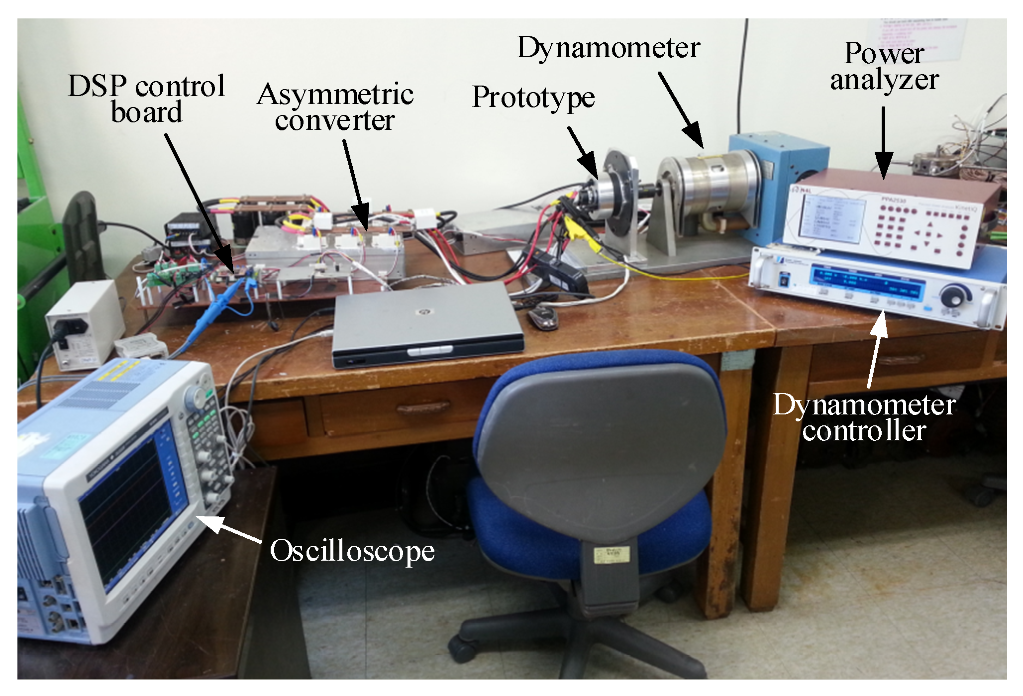
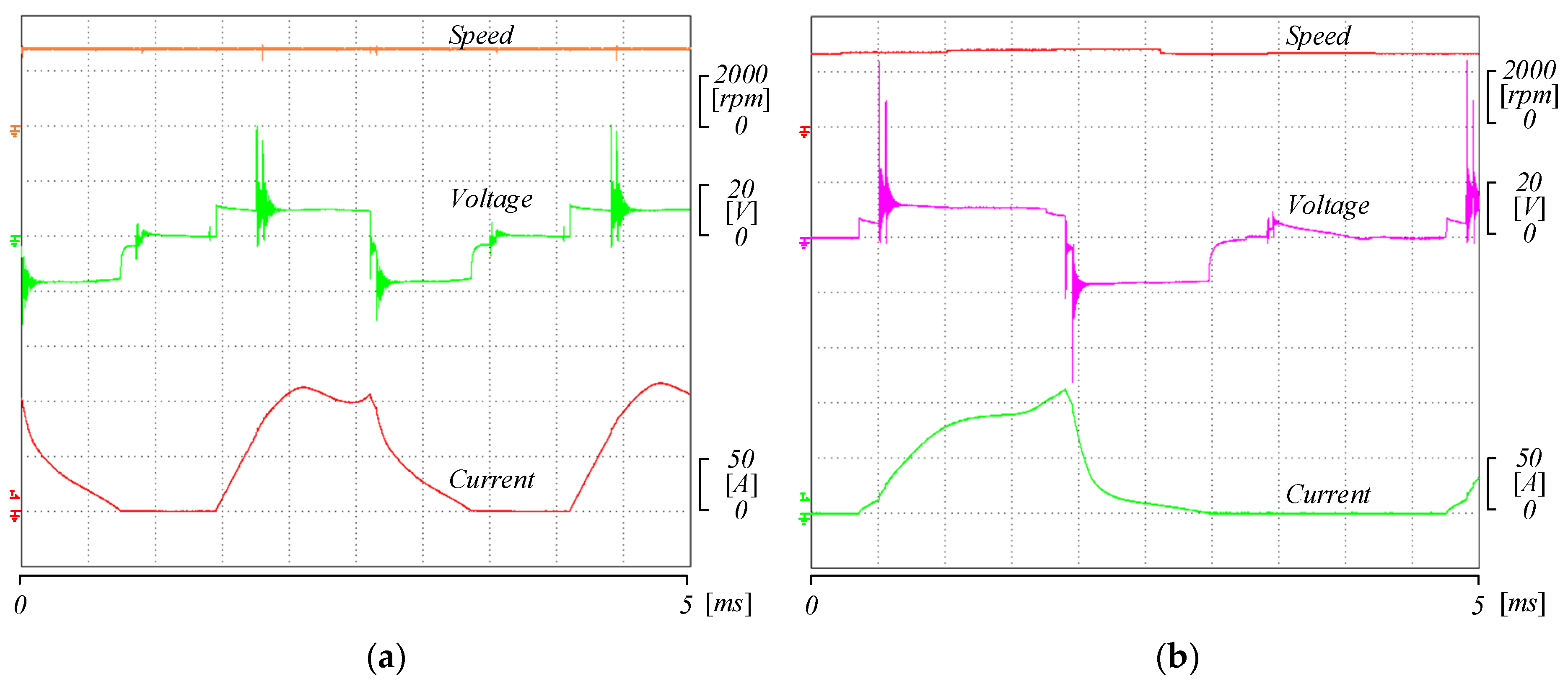
4. Experimental Verification

Figure 15 shows the prototypes of the traditional 12/8 and proposed 6/5 SRMs, which are made on the basis of the dimensions in Table 1. The stator and rotor of the prototypes are made of silicon steel sheet and the type of the silicon steel sheet is 35PN440. The shaft, rotor end ring and nonmagnetic isolator of the prototypes are made of solid steel. The steel type for the shaft, rotor end ring and nonmagnetic isolator of the prototypes are S45C, brass C2600 and brass C2600, respectively. At the same time, a test platform for the two motors, as shown in Figure 16, is built based on the control scheme and topology of the asymmetric converter, presented in Section 3.4. In the test platform, the DSP control board is used for controlling the operation of the motor. The power analyzer and dynamometer controller are used for measuring the active input power and controlling the load torque, respectively. The oscilloscope is used for acquiring the experimental data and waveform.
Figure 17 shows a comparison between the measured inductance and those predicted using FEA in the proposed 6/5 SRM. As is shown, the measured curve has a good match with the predicted curve, which verifies the correctness of the results of FEA.
Figure 18 shows the test results of the two motors under rated operating conditions. In the test, the control scheme is the same as that in the simulation. As is shown, the test results are in good agreement with the simulation results, shown in Figure 13, with the exception of the noise on the voltage curves. The noise mentioned above mainly arises from the switches.
Table 3 shows the comparison of the steady-state characteristics of the two motors under rated operating conditions in the test. In Table 3, the mechanical loss Pm is measured in the experiment. The stray loss Ps is still estimated at 6% of the total losses. The input power Pin is directly tested by the power analyzer and the output power Pout is directly obtained from the dynamometer controller. For the core loss Pcore, it could be calculated as
P c o r e = P i n P o u t P c u P m P s
in which the copper loss Pcu is calculated with Equation (5). Then, the motor efficiency η could be calculated with Equation (6). It can be seen in Table 3 that the results calculated by FEA matches well with those measured by the test. The efficiency error is only approximately 2%, which further proves the correctness of the FEA results. Furthermore, the proposed 6/5 type has slightly less mechanical loss compared to that of the traditional 12/8 type. This can be explained by the lack of any mechanical protrusion in the rotor of the proposed 6/5 type, compared to the rotor of traditional 12/8 type, resulting in reduced wind resistance.
Overall, it could be concluded that the proposed 6/5 type could increase the electric utilization of the motor, decrease the requirement of MMF in the motor, reduce the core loss of the motor and improve the efficiency of the motor in contrast with the traditional 12/8 type, which proves the effectiveness of the proposed 6/5 type.

5. Conclusions

In this paper, a novel 6/5 SRM with concentrated windings and a segmental rotor is proposed for torque density and efficiency improvement. The structures of the traditional 12/8 and proposed 6/5 SRMs are first illustrated in detail. Then, the characteristics, including magnetic field vector, magnetic flux density, inductance, torque and steady-state, of the two motors are analyzed and compared. In the analysis results, it could be found that, with the turns number of windings per phase 30% lower than that of the traditional 12/8 SRM, the proposed 6/5 SRM could produce more torque compared to that of the traditional 12/8 SRM under the same phase current, and the increase advantage is maintained by at least 25% at all current levels. Furthermore, under rated operating conditions, the proposed 6/5 SRM has significantly lower copper loss and core loss, and nearly 5% higher efficiency, which proves the validity of the proposed motor. In addition, the prototypes of the two motors are manufactured. On the basis of the prototypes, the experiments, including static-state and steady-state, are performed, respectively. The experiment results have a good match with those calculated by FEA, which further proves the effectiveness of the proposed structure.

Author Contributions

Conceptualization, Z.X.; methodology, H.W. and D.-H.L.; software, Z.X. and T.L.; validation, Z.X. and T.L.; formal analysis, Z.X. and T.L; investigation, T.L.; resources, Z.X. and H.W.; data curation, Z.X. and T.L.; writing—original draft preparation, Z.X. and T.L.; writing—review and editing, Z.X., F.Z. and J.-W.A.; visualization, Z.X.; supervision, F.Z., D.-H.L. and J.-W.A.; project administration, Z.X. and F.Z.; funding acquisition, Z.X and F.Z. All authors have read and agreed to the published version of the manuscript.

Funding

This research was funded by the National Natural Science Foundation of China under Grant 52077141, 52211540392 and 51920105011, Natural Science Foundation of Liaoning Province of China under Grant 2022-MS-269, Shenyang Young and Middle-Aged Science and Technology Innovation Talent Support Program of China under Grant RC200427.

Institutional Review Board Statement

Not applicable.

Informed Consent Statement

Not applicable.

Data Availability Statement

Not applicable.

Conflicts of Interest

The authors declare no conflict of interest.

References

  1. Mecrow, B.C.; Finch, J.W.; I-Kharashi, E.A.E.; Jack, A.G. Switched reluctance motors with segmental rotors. IEEE Proc. Electr. Power Appl. 2002, 149, 245–254. [Google Scholar] [CrossRef]
  2. Oyama, J.; Higuchi, T.; Abe, T.; Tanaka, K. The fundamental characteristics of novel switched reluctance motor with segment core embedded in aluminum rotor block. J. Electr. Eng. Technol. 2006, 1, 58–62. [Google Scholar] [CrossRef] [Green Version]
  3. Higuchi, T.; Suenaga, K.; Abe, T. Torque ripple reduction of novel segment type switched reluctance motor by increasing phase number. In Proceedings of the 2009 International Conference on Electrical Machine and Systems (ICEMS 2009), Tokyo, Japan, 15–18 November 2009. [Google Scholar]
  4. Higuchi, T.; Nakao, Y.; Abe, T. Characteristics of a novel segment type SRM with 2-step slide rotor. In Proceedings of the 2009 International Conference on Electrical Machine and Systems (ICEMS 2009), Tokyo, Japan, 15–18 November 2009. [Google Scholar]
  5. Chen, X.Y.; Deng, Z.Q.; Wang, X.L.; Peng, J.J.; Li, X.S. New designs of switched reluctance motors with segmental rotors. In Proceedings of the 5th IET International Conference on Power Electronics, Machines and Drives (PEMD 2010), Brighton, UK, 19–21 April 2010. [Google Scholar]
  6. Lan, Y.; Peng, W.; Aksoz, A.; Benomar, Y.; Bossche, P.V.; Baghdadi, M.E.; Hegazy, O. Design and modelling of 12/4 fully-pitched segmental switched reluctance motors. In Proceedings of the 2020 Fifteenth International Conference on Ecological Vehicles and Renewable Energies (EVER 2020), Monte-Carlo, Monaco, 10–12 September 2020. [Google Scholar]
  7. Vandana, R.; Vattikuti, N.; Fernandes, B.G. A novel high power density segmented switched reluctance machine. In Proceedings of the 2008 IEEE Industry Applications Society Annual Meeting, Edmonton, AB, Canada, 5–9 October 2008. [Google Scholar]
  8. Mecrow, B.C.; I-Kharashi, E.A.E.; Finch, J.W.; Jack, A.G. Segmental rotor switched reluctance motors with single-tooth windings. IEEE Proc. Electr. Power Appl. 2003, 150, 591–599. [Google Scholar] [CrossRef]
  9. Mecrow, B.C.; I-Kharashi, E.A.E.; Finch, J.W.; Jack, A.G. Preliminary performance evaluation of switched reluctance motors with segmental rotors. IEEE Trans. Energy Convers. 2004, 19, 679–686. [Google Scholar] [CrossRef]
  10. Widmer, J.D.; Martin, R.; Mecrow, B.C. Optimization of an 80-kW segmental rotor switched reluctance machine for automotive traction. IEEE Trans. Ind. Appl. 2015, 51, 2990–2999. [Google Scholar] [CrossRef]
  11. Xu, Z.; Liu, J.; Kim, M.J.; Lee, D.H.; Ahn, J.W. Characteristics analysis and comparison of conventional and segmental rotor type 12/8 switched reluctance motors. IEEE Trans. Ind. Appl. 2019, 55, 3129–3137. [Google Scholar] [CrossRef]
  12. Sun, X.; Diao, K.; Lei, G.; Guo, Y.; Zhu, J. Real-time HIL emulation for a segmented-rotor switched reluctance motor using a new magnetic equivalent circuit. IEEE Trans. Power Electron. 2020, 35, 3841–3849. [Google Scholar] [CrossRef]
  13. Sun, X.; Diao, K.; Lei, G.; Guo, Y.; Zhu, J. Study on segmented-rotor switched reluctance motors with different rotor pole numbers for BSG system of hybrid Electric vehicles. IEEE Trans. Veh. Technol. 2019, 68, 5537–5547. [Google Scholar] [CrossRef]
  14. Sun, W.; Li, Q.; Sun, L.; Zhu, L.; Li, L. Electromagnetic analysis on novel rotor-segmented axial-field SRM based on dynamic magnetic equivalent circuit. IEEE Trans. Magn. 2019, 55, 1–5. [Google Scholar] [CrossRef]
  15. Sun, X.; Shen, Y.; Wang, S.; Lei, G.; Yang, Z.; Han, S. Core losses analysis of a novel 16/10 segmented rotor switched reluctance BSG motor for HEVs using nonlinear lumped parameter equivalent circuit model. IEEE/ASME Trans. Mechatron. 2018, 23, 747–757. [Google Scholar] [CrossRef]
  16. Al-Amyal, F.; Hamouda, M.; Száme, L. Performance improvement based on adaptive commutation strategy for switched reluctance motors using direct torque control. Alex. Eng. J. 2022, 61, 9219–9233. [Google Scholar] [CrossRef]
  17. Al-Amyal, F.; Számel, L. Research on novel hybrid torque sharing function for switched reluctance motors. IEEE Access 2022, 10, 91306–91315. [Google Scholar] [CrossRef]
Figure 1. Diagram of traditional 12/8 SRM structure.
Energies 15 08915 g001
Figure 2. Magnetic field vector of traditional 12/8 SRM. (a) Phase A windings excited only; (b) Phase B windings excited only; (c) Phase C windings excited only.
Energies 15 08915 g002
Figure 3. Diagram of traditional 12/8 SRM structure.
Energies 15 08915 g003
Figure 4. Magnetic field vector of proposed 6/5 SRM. (a) Phase A windings excited only; (b) Phase B windings excited only; (c) Phase C windings excited only.
Energies 15 08915 g004
Figure 5. Magnetic flux density in the two motors. (a) Traditional 12/8 SRM; (b) Proposed 6/5 SRM.
Energies 15 08915 g005
Figure 6. Three-dimensional inductance curves. (a) Traditional 12/8 SRM; (b) Proposed 6/5 SRM.
Energies 15 08915 g006
Figure 7. Inductance comparison between the two motors.
Energies 15 08915 g007
Figure 8. Three-dimensional torque curves. (a) Traditional 12/8 SRM; (b) Proposed 6/5 SRM.
Energies 15 08915 g008
Figure 9. Average torque comparison in the two motors. (a) Average torque in absolute value; (b) Average torque in relative value.
Energies 15 08915 g009
Figure 10. Topology of the asymmetric converter for the two motors.
Energies 15 08915 g010
Figure 11. Control scheme for the two motors.
Energies 15 08915 g011
Figure 12. Simulation driving circuit for the two motors.
Energies 15 08915 g012
Figure 13. Simulation results under rated operating conditions. (a) Traditional 12/8 SRM; (b) Proposed 6/5 SRM.
Energies 15 08915 g013
Figure 14. Transient torque and core loss of the two motors under rated operating conditions. (a) Transient torque; (b) Transient core loss.
Energies 15 08915 g014
Figure 15. Prototypes of traditional and proposed SRMs. (a) Rotor of traditional 12/8 and proposed 6/5 SRMs; (b) Stator of traditional 12/8 SRM; (c) Stator of proposed 6/5 SRM.
Energies 15 08915 g015
Figure 16. Test platform for the two motors.
Energies 15 08915 g016
Figure 17. Comparison between measured inductance and those predicted using FEA in the proposed 6/5 SRM.
Energies 15 08915 g017
Figure 18. Test results under rated operating conditions. (a) Traditional 12/8 SRM; (b) Proposed 6/5 SRM.
Energies 15 08915 g018
Table 1. Dimensions of traditional and proposed SRMs.
ParameterTraditional 12/8 SRMProposed 6/5 SRM
Stator outer radius (mm)52.552.5
Stator inner radius (mm)31.2526.25
Rotor inner radius (mm)24N/A
Shaft radius (mm)44
Air gap (mm)0.250.25
Stator yoke thickness (mm)510
Stator pole arc (deg.)1454/30
Rotor pole arc (deg.)1666
Stack length (mm)3535
Turns number of windings per phase2014
Resistance per phase (mΩ)7.06.9
Table 2. Steady-state characteristics comparison of the two motors under rated operating condition in simulation.
ParameterTraditional 12/8 SRMProposed 6/5 SRM
Rated speed (r/min)28002800
Rated torque (N.m)1.71.7
Switch-on angle (deg.)23.333.8
Switch-off angle (deg.)40.961.0
Torque ripple (%)97.0126.4
RMS value of phase current (A)62.553.9
Copper loss (W)82.559.4
Core loss (W)20.310.5
Mechanical loss (W)12.512.5
Stary loss (W)7.35.3
Output power (W)498.5498.5
Input power (W)621.1586.2
Efficiency (%)80.385.0
Table 3. Steady-state characteristics comparison of the two motors under rated operating condition in test.
ParameterTraditional 12/8 SRMProposed 6/5 SRM
SimulationTestSimulationTest
Rated speed (r/min)2800280028002800
Rated torque (N.m)1.71.71.71.7
RMS value of phase current (A) 62.564.953.955.1
Copper loss (W)82.588.459.462.8
Core loss (W)20.327.110.517.9
Mechanical loss (W)12.514.312.513.4
Stary loss (W)7.38.35.36.0
Output power (W)498.5498.1498.5498.1
Input power (W)621.1636.2586.2598.2
Efficiency (%)80.378.385.083.3
Publisher’s Note: MDPI stays neutral with regard to jurisdictional claims in published maps and institutional affiliations.

