Abstract
This paper presents the measured energy losses in a draw gear with NE22, XH500, LL2, and CFG flat belts. The ranges of torque capacity, slippage occurrence, and transmission efficiency of selected drive belts are also presented. Knowing the exact values of these parameters allows the selection of the most suitable belts for different applications. In addition, belt manufacturers do not provide these data accurately, leading to machine failures and downtime. The paper describes the dependence of belt efficiency and belt slippage as a function of transmission load. Running transmissions with high slippage values are associated with a significant loss of energy and efficiency, rapid wear of the belt and pulleys, and increased operating temperature. In addition, when flat belts are under excessive load, it is common for the belt to quickly fall off the pulleys, interrupting the operation of machinery and equipment. Experiments on a test bench can accurately determine the energy loss caused by transmission belt slippage. The maximum achievable torque of the belt selected for the study, which differed in construction and materials, was around 6 Nm for LL2, XH500, and CFG and 12 Nm for NE22. Slippage reached values of 0.005 to 0.1, while efficiency ranged between 0.60 and 0.97.
1. Introduction
Flat-belt transmissions were among the first drives used to transmit torque over a considerable distance. Initially, they were made from animal skins. Thanks to the development of new materials and other types of belts, using such belts has declined considerably. Today, many belts are constructed of several layers of different materials that are resistant to both wear and heat. Transmissions with flat belts can be used for power transmission and act as a clutch in the event of slippage. Permanent slippage on the wheels will not damage such a belt and, when the load is reduced, the transmission will return to its original function. For belts operating in harsh environmental conditions, suitable types of rubber are chosen, usually polymers, while steel is used for high-pressure and very harsh operating conditions.
A large proportion of belts are those used in conveyors [1,2,3]. In modern flat belts, the backing is made of materials that ensure minimum elongation, while maintaining flexibility in small-diameter wheels. The coupling of the belt to the wheels depends largely on the material used on the running side. The work of researchers and belt designers has resulted in a virtually inextensible cord, but the problem remains as to its mass and thickness [4,5]. The primary purpose of belt transmissions is to transmit torque over long distances, so they are commonly used in manipulators. Other transmissions that can also do this include gears, chains, etc., but belts are used because they are light and the transmission does not make excessive noise; the advantage of these transmissions is a relatively high efficiency. Belt gears are mostly made of synthetic and natural polymers, wherein the consumption of the binding energy between the polymer chains causes the material structure to weaken and break. Belts are also made of crystalline materials, such as steel belts, and in this case, fatigue can occur after a certain period. Volumetric wear is mainly related to abrasion, although the material is also crushed. In polymer belts, crushing occurs in the first cycles of operation and, of course, after a long period due to material creep [6,7,8]. Abrasion occurs in all drive and conveyor belts and results from friction or frictional coupling of the belt and wheels. In the actual belt transmission, slippage of the belt over the wheel is related to the compensation of the elongation of the active belt concerning the passive belt. Belts and pulleys are selected so that the belt-wheel friction pair provides the highest possible gearbox efficiency, followed by the abrasion design. In recent years, the chemical industry has made significant progress in developing new materials to manufacture belts that can perform traction or transport functions. Some belts combine these two functions, wherein the belt must be mounted and run in the correct direction. In addition to their many advantages, these transmissions have several disadvantages. Sources of malfunction in power transmission may derive from inaccuracies in the manufacture and assembly of machinery and equipment [9,10]), imbalances in the rotational movement of components [11,12,13], wear of components, and temperature variations in gears. The latter characteristic can become a cause of belt inflammation. To reduce these adverse incidents, composites and materials with different structures are used to produce belts [14,15,16]. The energy intensity of conveyor belt processes depends on the belt type [17]. Belts are commonly used to drive mobile robots [18,19] and improve the constant-speed induction of a motor’s performance [20]. In contrast, an original approach to predict the gradual degradation behavior of conveyor belts used for pallet transport between machining stations is presented in [21]. When selecting the geometric properties of flat belt pulleys, their performance characteristics in traction and conveyor applications must be known. Many researchers have investigated V-belts’ slippage and Continuously Variable Transmission (CVT). Still, there is a lack of up-to-date data on the energy losses caused by slippage for modern flat belts. Slippage losses directly affect transmission efficiency. Kubas (2022) presented the measurement results of a belt transmission with a 5PK multibelt [22]. His work aimed to obtain the dependence of the belt slippage value at relatively high drag torque values. In another work, the same author presented a two-dimensional model of a belt transmission for dynamic analysis [23]. Batalia et al. (2015) investigated the slippage of a 1:1 ratio V-belt transmission using different experimental methodologies [24]. In another paper, Batalia et al. (2015) discussed the reduction in transmission torque and its effect on transmission efficiency [25]. In 2021, Bucchi and Frendo developed a model to check the speed loss in the drive and driven pulley using transmission parameters (e.g., preload, friction, pulley radii, etc.) and operating parameters (i.e., angular velocity and drag torque) [26]. In 2020, Frendo and Bucchi presented a new mathematical model for the analysis of contact interactions between belts and pulleys that was particularly suitable for a flat reinforced rubber belt [27]. In contrast, Mascenik and Murcinkova (2019) presented alternative options for determining the condition of a belt transmission based on testing and monitoring [28]. To perform experimental measurements, the article’s authors designed a device for testing, monitoring and diagnostics of belt drives. In 2019, Oborin presented a simplified model of belt motion with small deformations and the effects of moving the line of action of frictional forces to the center of the belt [29]. In 2021, Gawrońska et al., pointed out the problems associated with the failure of belt-driven transmission [30]. Drive belts are successfully used in many machines and devices for both power transmission and motion control of actuators [31,32,33,34].
The literature review carried out shows a lack of results on belt slip-induced energy loss for new commercial composite flat belts. This information is vital for designers and machine control engineers to properly diagnose and design machines and equipment using flat belt transmission. To understand the elusive characteristics of flat belt transmission, three main objectives had to be defined: the first was to determine the torque transmission range for the adopted transmission configuration; the second was to determine the speed losses at the active and idler shafts and, on this basis, to determine the belt slippage; the third objective was to determine the torque losses in the transmission and determine the efficiency of the transmission. Achieving the study’s purposes made it possible to identify essential design features of the belt transmission where the belts differ significantly in material with exact geometric dimensions (belt width of 20 mm), while concurrently providing a popular design solution on the market.
2. Materials and Methods
2.1. Materials
Four flat belts were tested: neoprene (NE22), extra high top cower (XH500), leder leder (LL2), and a cotton, polyester, and polyester fabric belt called the CFG.
Figure 1 shows a 1.4 mm thick flat NE22 belt made of an endlessly woven polyester layer and a polychloroprene coating. It is characterized by abrasion resistance, a high friction coefficient, and good resistance to oil, grease, and ozone. It can be used up to a linear speed of 100 m/s. It has antistatic properties, high elasticity, and can be used on small-diameter pulleys. It is used in high-speed drives in the textile industry (spindle drives), paper and printing industries, and simple drives that do not require high kinematic efficiency.
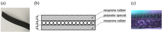
Figure 1.
NE22 flat lane (a) photography, (b) belt cross section, (c) optical light microscopy images of the internal structure.
Figure 2 shows a 3 mm thick XH 500 belt constructed in four layers. The upper and lower layers are NBR nitrile (acrylonitrile butadiene) rubber, and the middle layers are PA polyamide and PAFab polyamide weaving. The belt is characterized by excellent wear resistance, high elasticity, minimal maintenance, high efficiency, and long service life. At the same time, it is resistant to oils, moisture, and is antistatic. It is used in printing plants (folding-gluing machines) in packaging production.
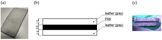
Figure 2.
LL2 flat lane (a) photography, (b) belt cross section, (c) optical light microscopy images of the internal structure.
The LL2-type flat belt (Figure 3) is made of three alternating layers of leather and PA6 (polyamide 6). Such belts are used in multi-shaft drives and contaminated working environments, and are characterized by good resistance to varying loads and their ability to act as overload couplings. They are characterized by short permanent slippage, good wheel interaction (the wheel does not damage the belt), and antistatic properties. The LL2 belt is designed for a temperature range of −20 C to +100 °C. A closed belt is obtained by grinding the ends at an angle and welding at 100–120 °C for 15 min. LL2-type belts are used in mills, chippers, woodworking machinery and equipment. The last belt tested, CFG (Figure 4), was 3.4 mm thick and made of three layers of polyester fabric, with the running side made of impregnated polyester fabric and the belt cover made of cotton fabric. It can be joined by finger-jointing, overlapping, gluing, or mechanical means. The temperature range it can withstand is −30 °C to +140 °C. The CFG belt is used, for example, to transport rubber. The structures of all the belts tested during operation, along with their markings, and the morphology of the belt composites observed by optical light microscopy are summarized.
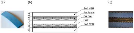
Figure 3.
XH 500 flat lane (a) photography, (b) belt cross section, (c) optical light microscopy images of the internal structure.
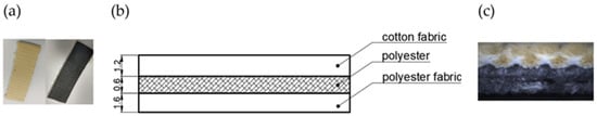
Figure 4.
CFG flat lane (a) photography, (b) belt cross section, (c) optical light microscopy images of the internal structure.
2.2. Test Stand
The aims of the work were realized by utilizing a test rig with two equal diameter wheels of 63 mm (ratio 1:1), with a belt width of 20 mm in each case and a shaft center distance of 660 mm (Figure 5). A hydraulic motor was mounted on the base of the stand. The transmission from the active shaft of the motor was transferred to the active shaft of the belt drive by utilizing flexible couplings. A torque meter was placed between the clutches. A rotary-code sensor was attached to the pulley face via a pin. Similarly, a torque meter was mounted on the passive shaft. A magnetorheological brake was used to set the load in the tested transmission, which was adjusted by a power supply in the laboratory. The signals from the torque and torque-code sensors were fed to a measuring amplifier and then to a computer. The speed control of the system was carried out independently of the recording system by using an additional inductive sensor for speed measurement.
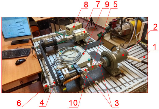
Figure 5.
Test stand for kinematic and dynamic characteristics of the transmission, where: 1—stand base, 2—hydraulic motor, 3—flexible coupling, 4—active shaft of the belt transmission, 5—torque meter, 6—rotary-code sensor, 7—magnetorheological brake, 8—laboratory power supply, 9—measuring amplifier, 10—inductive sensor.
The second task for which the designed bench was used was torque measurement. A set of T5 torque gauges from Hottinger Baldwin Messtechnik GmbH HBM (Darmstadt, Germany) were used to achieve high-precision measurements. These torque sensors have an accuracy class of 0.1. The sensors were used with the SPIDER-8 universal measurement amplifier, which is manufactured by Hottinger Baldwin Messtechnik GmbH, together with the CATMAN software for storing and processing the measurement results. This software not only allowed the necessary settings and configuration of the amplifier to be carried out, but also allowed the results to be stored in the CATMAN’s internal format. The software also enabled results to be exported to other programs, e.g., Excel.
Braking torque variations were induced using a stabilized laboratory power supply with infinitely variable voltage from 0 to 30 V and a current adjustment from 0–5 A.
Belt tension was monitored using an instrument called PICCOLA from SIT Antriebselemente GmbH (Brakel, Germany). The instrument directly indicates the vibration frequency from which the user can determine the belt tension force in the belt transmission. The calculated vibration frequency is equivalent to the relationship (1):
Fv—belt tension force (N)
m—belt mass per linear meter (kg/m)
L—length of the vibrating belt (m)
f—belt vibration frequency (Hz).
The measurement error of this input in the range of 10 to 400 Hz is ± 1 Hz.
2.3. Research Methodology
A common feature of the tested belts is operation at speeds up to 1500 rpm. For this reason, tests were carried out for three rotational speeds of 500 rpm, 1000 rpm, 1500 rpm and several brake torque settings. The adopted range of test parameters was the rotational speed and braking torque values, which ensured the correct operation of the transmission. The adopted test method made it possible to determine the relationship between the input parameters and the transferable torque, as well as belt slippage caused by the loss of speed and torque on the idler wheel and the transmission efficiency.
Belt slippage was determined from the relationship (2):
where:
n1—active wheel speed,
n2—passive wheel speed.
In turn, the transmission efficiency wattage was calculated using formula (3):
where:
M1—active wheel torque,
M2—torque on the passive wheel.
Ten speed and torque measurements were carried out on the active and passive shafts.
Belt tension checks were carried out cyclically after each series of tests. Table 1 shows the average belt tension in hertz determined from five measurements.

Table 1.
Belt vibration frequency values with correct belt tension.
In the analysis of the measurement error, the arithmetic mean was taken as the estimator of the desired value, and the standard deviation of the arithmetic mean was taken as the estimator’s error.
3. Results and Discussion
The braking torque value for the NE22, LL2, and CFG belts was about 6 Nm, while for the NE22 belt, it was twice as high (about 12 Nm) at speeds between 500 rpm and 1500 rpm.
Figure 6a illustrates the efficiency variation as a function of torque on the passive shaft at an active shaft speed of 500 rpm. Figure 6b shows the slippage variation as a function of torque on the idler shaft for NE22, XH500, LL2, and CFG belts at a 500 rpm active shaft speed.
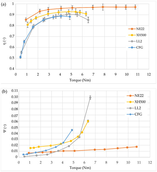
Figure 6.
Variation characteristics of (a) efficiency as a function of torque at the idler shaft (b) belt slippage as a function of torque at the idler shaft for a speed of 500 rpm.
The efficiency values determined from the measurements show significant differences in both the transferable torque range and the slippage of the individual belts. The smallest torque range was that of the CFG belt, from 2.5 Nm, where the efficiency value reached 0.85, to about 5 Nm, where the value was 0.88. The LL2 belt transmission had a torque range from 2.5 Nm, with an efficiency of 0.85 Nm, to 5.5 Nm, with an efficiency of 0.9. For the XH500 belt, the torque range was between 2.5 Nm at an efficiency of 0.89 and 5.5 Nm at an efficiency of 0.92. The last of the NE22 belts tested had the best characteristics, with a torque range between 2.5 Nm at an efficiency of 0.95 and 11 Nm at an efficiency of 0.96.
The belt slippage at 500 rpm is illustrated in Figure 6b. For a CFG belt, the value was 0.08 in the 1 Nm range up to about 4 Nm, where the value was 0.015. The LL2 belt had a slippage of 0.002 at 1 Nm torque and 0.020 at 4 Nm. Another XH500 belt showed the following performance: 1Nm had a slippage of 0.08, and 4 Nm had a slippage of 0.015. For the NE22 belt, with torque values between 0.8 Nm to 11 Nm, the slippage was 0.08 to 0.018, respectively.
Figure 7a shows the variation of transmission efficiency values as a function of changes in idler shaft torque for CFG, LL2, XH500, and NE22 belts at an active shaft speed of 1000 rpm.
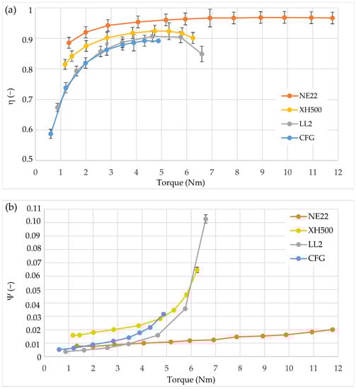
Figure 7.
Variation characteristics of: (a) efficiency as a function of idler shaft torque (b) belt slippage as a function of torque at the idler shaft at 1000 rpm.
The CFG belt’s torque range relevant to engineering practice is 2 Nm to 5.8 Nm, with efficiencies of 0.81 to 0.87. The LL2 belt for the torque range of 2 Nm to 5.7 Nm has efficiencies of 0.81 to 0.89, respectively. For the third XH500 belt tested, the efficiencies range from 0.86 to 0.90 for the other torque ranges. The last of the LL2 belts tested has a useful efficiency range of 0.90 to 0.96. Figure 7b illustrates the slippage variation as a function of torque. For the CFG belt, for a torque range of 2 Nm to 4.6 Nm, the slippage values were 0.003 and 0.01, respectively. The LL2 belt had slippage values of 0.003 and 0.017, respectively. The XH500 belt had an efficiency range of 0.018 to 0.03 in the same torque range. The last belt tested also had the most favorable characteristics for 500 rpm. Slippage was registered at a level between 0.01 and 0.017 in the same torque range.
Figure 8a shows the variation of transmission efficiency values as a function of changes in idler shaft torque for the CFG, LL2, XH500, and NE22 belts at an active shaft speed of 1500 rpm.
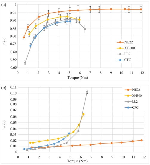
Figure 8.
Variation characteristics of (a) efficiency as a function of torque at the idler shaft (b) belt slippage as a function of torque at the idler shaft at 1500 rpm.
Figure 8a shows that the efficiency of the transmission with the CFG belt, like the other tested belts, was lowest at 1500 rpm and was 0.81 for a torque of 2 Nm. For a torque of 5 Nm, the efficiency of the transmission with the CFG belt was 0.87. The efficiency of the LL2 belt transmission in the torque range from 2 Nm to 5 Nm was 0.081 to 0.91. The efficiency of the LL2 belt transmission in the torque range from 2 Nm to 5 Nm was 0.081 to 0.91. The XH500 belt had an efficiency value of 0.87 to 0.92 in the torque range from 2 Nm to 5 Nm. The fourth belt tested had an efficiency value of 0.92 to 0.97 in the torque range from 2 Nm to about 12 Nm.
At a CFG belt speed of 1500 rpm, the slippage value (Figure 8b) for a torque of 2 Nm was 0.012, and for a value of 5 Nm was 0.03. The slippage value of the LL2 belt ranged from 0.006 to 0.02. The XH 500 belt had a slippage level of 0.017 to 0. 03.03. The NE22 belt showed a slippage level from 0.005 to 0.02 between 0.7 Nm and 12 Nm. The nature of the variation in slippage value increased with increasing torque, and these results are consistent with those of Balt et al. investigating V-ribbed belts [24,25]. Studies of the efficiency of Mascenik and Murcinkova flat belts have shown efficiencies in the calculated range of about 0.97 and measured efficiencies of about 0.99 at brake torque measurements from 1.25-3 Nm and rotational speeds from 1300 rpm to 2000 rpm [28]. In these value ranges, the belts studied in the paper had efficiencies of about 0.5 to 0.95. Above 3 Nm, on the other hand, their efficiencies were in the range of 0.88 to 0.98, indicating that Mascenik and Murcinkova studied belts that had better efficiencies at lower braking torque values [28]. Bajda and Hardygóra showed that, depending on the type of flat belt used (in a conveyor belt system), its energy intensity can vary by about 20% in real operating conditions [17]. Changes in the efficiency of the tested belts in the range of real loads (from 3 Nm to 6 Nm of braking torque) differed by about 27%, which directly affects the energy intensity, which was in a similar range as shown by Bajda and Hardygóra [17].
4. Conclusions
The authors’ objectives were to determine the potential torque transfer range, the value of belt slippage, and the efficiency of the adopted transmission configuration.
Based on the authors’ experimental study and results analysis, the following conclusions were drawn:
- -
- Belts with high efficiency had the lowest belt slippage. For this reason, materials with a high coefficient of friction concerning the wheel material are used on the running side of the belts, and this layer is made as thin as possible;
- -
- The thinner the layer, the higher the belt transmission efficiency;
- -
- Excessive increases in braking torque resulted in a significant increase in slippage and, consequently, in the belt falling off the wheels. This effect was mitigated by sufficiently high belt preload;
- -
- The NE22 has the most favorable characteristics of the belts tested, with the broadest torque transmission range of 0.7 Nm to 12 Nm. This belt had an efficiency of 97%, while slippage ranged from 0.005 to 0.02;
- -
- The highest energy loss was recorded for the CFG belt, the torque range was comparable to that of the XH500 and LL2 belts, and efficiency was around 90% in the very low torque range;
- -
- XH500 and LL2 belts showed similar transferable torque, slippage and efficiency values.
The experimental results presented here do not entirely evaluate the performance characteristics of NE22, XH500, LL2, CFG, and CFG flat belts. However, they may be helpful for both designers of belted drives and those involved in the operation of such drives. Many new flat belt designs have been developed in recent years, and advances in materials technology mean that more modern belts and more successful applications can be expected.
Author Contributions
Conceptualization, P.K., Ł.W., E.G. and Z.S.; methodology, P.K., K.J.W. and J.M.; software, E.G., ŁW.; validation, Ł.W., P.K.; formal analysis, Z.S., P.K. and J.M.; investigation, K.J.W., E.G.; resources, P.K. and Z.S.; data curation, J.M. and K.J.W.; writing—P.K., Ł.W.; writing—review and editing, Ł.W. and P.K.; visualization, Z.S. and J.M.; supervision, E.G.; project administration, P.K. and Ł.W.; funding acquisition, P.K., K.J.W. and Ł.W. All authors have read and agreed to the published version of the manuscript.
Funding
This research was funded by the Poznan University of Technology, grant number 0611/SBAD/0121.
Data Availability Statement
Not applicable.
Acknowledgments
Not applicable.
Conflicts of Interest
The authors declare no conflict of interest.
References
- Hrabovský, L.; Fries, J. Transport Performance of a Steeply Situated Belt Conveyor. Energies 2021, 14, 7984. [Google Scholar] [CrossRef]
- Stehlikova, B.; Molnar, V.; Fedorko, G.; Michalik, P.; Paulikova, A. Research about influence of the tension forces, asymmetrical tensioning and filling rate of pipe conveyor belt filled with the material on the contact forces of idler rolls in hexagonal idler housing. Measurement 2020, 156, 107598. [Google Scholar] [CrossRef]
- Gierz, Ł.; Warguła, Ł.; Kukla, M.; Koszela, K.; Zwiachel, T.S. Computer aided modeling of wood chips transport by means of a belt conveyor with use of discrete element method. Appl. Sci. 2020, 10, 9091. [Google Scholar] [CrossRef]
- Fedorko, G.; Molnar, V.; Vasil, M.; Salai, R. Proposal of digital twin for testing and measuring of transport belts for pipe conveyors within the concept Industry 4.0. Measurement 2021, 174, 10897. [Google Scholar] [CrossRef]
- Wozniak, D.; Hardygora, M. Method for laboratory testing rubber penetration of steel cords in conveyor belts. Min. Sci. 2020, 27, 105–117. [Google Scholar] [CrossRef]
- Marasova, D.; Ambrisko, L.; Caban, L. Determination of the Quality of Rubber Composites Based on their Testing. Qual. Access Success 2019, 20, 18–21. [Google Scholar]
- Czarnecka-Komorowska, D.; Sterzynski, T.; Dutkiewicz, M. Polyoxymethylene/Polyhedral Oligomeric Silsesquioxane Composites: Processing, Crystallization, Morphology and Thermo-Mechanical Behavior. Int. Polym. Process. 2016, 31, 598–606. [Google Scholar] [CrossRef]
- Czarnecka-Komorowska, D.; Sterzynski, T.; Andrzejewski, J. Evaluation of structure and thermomechanical properties of polyoxymethylene modified with polyhedral oligomeric silsesquioxanes (POSS). Przem. Chem. 2013, 92, 2129–2132. [Google Scholar]
- Sika, R.; Rogalewicz, M.; Popielarski, P.; Czarnecka-Komorowska, D.; Przestacki, D.; Gawdzińska, K.; Szymański, P. Decision support system in the field of defects assessment in the metal matrix composites castings (Open Access). Materials 2020, 13, 3552. [Google Scholar] [CrossRef]
- Krawiec, P.; Grzelka, M.; Kroczak, J.; Domek, G.; Kołodziej, A. A proposal of measurement methodology and assessment of manufacturing methods of nontypical cog belt pulleys. Measurement 2019, 132, 182–190. [Google Scholar] [CrossRef]
- Krawiec, A.; Marlewski, A. Profile design of noncircular belt pulleys. J. Theor. Appl. Mech. 2016, 54, 561–570. [Google Scholar] [CrossRef]
- Krawiec, P. Analysis of selected dynamic features of a two-whwwled transmission system. J. Theor. Appl. Mech. 2017, 55, 461–467. [Google Scholar] [CrossRef]
- Kujawski, M.; Krawiec, P. Analysis of Generation Capabilities of Noncircular Cog belt Pulleys on the Example of a Gear with an Elliptical Pitch Line. J. Manuf. Sci. Eng. -Trans. ASME 2011, 133, 051006. [Google Scholar] [CrossRef]
- Wałęsa, K.; Malujda, I.; Górecki, J. Experimental research of the mechanical properties of the round drive belts made of thermoplastic. IOP Conf. Ser. Mater. Sci. Eng. 2020, 776, 012107-1–012107-11. [Google Scholar] [CrossRef]
- Wojtkowiak, D.; Talaśka, K. The influence of the piercing punch profile on the stress distribution on its cutting edge. MATEC Web Conf. 2019, 254, 02001. [Google Scholar] [CrossRef][Green Version]
- Berdychowski, M.; Malujda, I.; Wałęsa, K.; Fierek, A. Analysis of angular deflection of bearing node in machine with toothed transport belt. IOP Conf. Ser. Mater. Sci. Eng. 2020, 776, 012019. [Google Scholar] [CrossRef]
- Bajda, M.; Hardygóra, M. Analysis of the Influence of the Type of Belt on the Energy Consumption of Transport Processes in a Belt Conveyor. Energies 2021, 14, 6180. [Google Scholar] [CrossRef]
- Sága, M.; Jakubovičová, L. Simulation of vertical vehicle non-stationary random vibrations considering various speeds. Sci. J. Sil. Univ. Technol. Ser. Transp. 2014, 84, 113–118. [Google Scholar]
- Kuric, I.; Bulej, V.; Saga, M.; Pokorny, P. Development of simulation software for mobile robot path planning within multilayer map system based on metric and topological maps. Int. J. Adv. Robot. Syst. 2017, 14, 1729881417743029. [Google Scholar] [CrossRef]
- Xiao, H.; Chuang, H.C.; Yang, Z.H.; Lee, C.T. The efciency improvement of induction motor with constant speed for belt drive mechanism. Energy Effic. 2021, 14, 87. [Google Scholar] [CrossRef]
- Elahi, M.; Afolaranmi, S.O.; Mohammed, W.M.; Martinez Lastra, J.L. Energy-Based Prognostics for Gradual Loss of Conveyor Belt Tension in Discrete Manufacturing Systems. Energies 2022, 15, 4705. [Google Scholar] [CrossRef]
- Kubas, K. Measurement of the friction parameters of a belt transmission under heavy load. Arch. Motoryz. 2022, 95, 18–31. [Google Scholar] [CrossRef]
- Kubas, K. A model for the dynamic analysis of a belt transmission using the Dahl friction model. J. Theor. Appl. Mech. 2017, 55, 1423–1435. [Google Scholar] [CrossRef]
- Balta, B.; Sonmez, F.O.; Cengiz, A. Speed losses in V-ribbed belt drives. Mech. Ma-Chine Theory 2015, 86, 1–14. [Google Scholar] [CrossRef]
- Balta, B.; Sonmez, F.O.; Cengiz, A. Experimental identification of the torque losses in V-ribbed belt drives using the response surface method. Proc. Inst. Mech. Eng. Part D J. Automob. Eng. 2015, 229, 1070–1082. [Google Scholar] [CrossRef]
- Bucchi, F.; Frendo, F. Analysis of belt transmissions capabilities using the brush model. Inst. Phys. Conf. Ser. Mater. Sci. Eng. 2021, 1038, 012076. [Google Scholar] [CrossRef]
- Frendo, F.; Bucchi, F. “Brush model” for the analysis of flat belt transmissions in steady-state conditions. Mech. Mach. Theory 2020, 143, 103653. [Google Scholar] [CrossRef]
- Mascenik, J.; Murcinkowa, Z. Experimental determination of the belt transmission slip. Manag. Syst. Prod. Eng. 2019, 4, 205–210. [Google Scholar] [CrossRef]
- Oborin, E. Belt–pulley interaction: Role of the action line of friction forces. Acta Mech. 2020, 231, 3979–3987. [Google Scholar] [CrossRef]
- Gawrońska, E.; Domek, G.; Krawiec, P.; Kołodziej, A. Modeling the damages of belt gears. IOP Conf. Ser. Mater. Sci. Eng. 2021, 1199, 012017. [Google Scholar]
- Blatnická, M.; Sága, M.; Blatnický, M. Design of pallet, frame and chain of soldering station conveyor. MATEC Web Conf. 2018, 157, 0100122. [Google Scholar] [CrossRef]
- Nikonova, T.; Zharkevich, O.; Dandybaev, E.; Baimuldin, M.; Daich, L.; Sichkarenko, A.; Kotov, E. Developing a Measuring System for Monitoring the Thickness of the 6 m Wide HDPE/LDPE Polymer Geomembrane with Its Continuous Flow Using Automation Equipment. Appl. Sci. 2021, 11, 10045. [Google Scholar] [CrossRef]
- Kuric, I.; Tlach, V.; Sága, M.; Císar, M.; Zajačko, I. Industrial Robot Positioning Performance Measured on Inclined and Parallel Planes by Double Ballbar. Appl. Sci. 2021, 11, 1777. [Google Scholar] [CrossRef]
- Blatnický, M.; Dižo, J.; Gerlici, J.; Sága, M.; Lack, T.; Kuba, E. Design of a robotic manipulator for handling products of automotive industry. Int. J. Ofdvanced Robot. Syst. 2020, 17, 1729881420906290. [Google Scholar] [CrossRef]
Publisher’s Note: MDPI stays neutral with regard to jurisdictional claims in published maps and institutional affiliations. |
© 2022 by the authors. Licensee MDPI, Basel, Switzerland. This article is an open access article distributed under the terms and conditions of the Creative Commons Attribution (CC BY) license (https://creativecommons.org/licenses/by/4.0/).