Article

The Instability Characteristics and Displacement Law of Coal Wall Containing Joint Fissures in the Fully Mechanized Working Face with Great Mining Height

Key Laboratory of Western Mine Exploitation and Hazard Prevention with Ministry of Education, School of Energy Engineering, Xi’an University of Science and Technology, Xi’an 710054, China
*
Author to whom correspondence should be addressed.
Energies 2022, 15(23), 9059; https://doi.org/10.3390/en15239059
Submission received: 23 October 2022 / Revised: 25 November 2022 / Accepted: 27 November 2022 / Published: 30 November 2022

Abstract

:
Coal wall rib-spalling is regarded as a key technical problem influencing safe and efficient mining of fully mechanized working face with great mining height (FGH) while the coal wall stability is influenced by the strength of the coal body, of which the internal joint fissures have a crucial impact on the strength of the coal body. This research attempted to explore how the coal wall stability of FGH is influenced by the occurrence of joint fissures. This paper uses physical and numerical simulations to systematically analyze the instability characteristics and displacement law of FGH. Research results show that the form and scope of the instability of coal wall rib-spalling depend on the state of the coal seam joint fissures development area, and the development state of coal seam joint fissures is related to the combination of the coal seam joints; under the condition of hard coal, the coal wall stability is better at the inclination angle of 90°, and less stable at 45° and 135°; under the condition of medium-hard coal and joint surface inclination angle of 45° and 135°, the smaller the spacing of joint surface, the larger the area of the working face rib-spalling, and the less stable the coal wall.

Graphical Abstract

1. Introduction

In China, the conditions for coal seam occurrence are complex, and with the widespread use of fully mechanized working face with great mining height (FGH), coal wall rib-spalling influence on the coal wall stability of FGH has become a key technical problem influencing safe and efficient mining of FGH [1,2,3,4,5,6,7,8,9,10,11]. Coal wall stability is influenced by the main roof movement of the working face, coal body strength, and support, among which the internal joints fissures of the coal body have a crucial influence on the coal body strength.
The coal seam, as a geodetic medium, is formed during a long period of geological history, and through complex geological action, weak surfaces such as joints, laminae, and fissures of different genesis exist within it [12,13,14,15,16,17]. From the damage mechanics’ point of view, a large number of intermittent joint fissures inside the coal body constitute the initial damage of the coal body, so the coal body also belongs to a medium with initial damage [18]. Therefore, during the retrieval process of FGH, the primary joint fissures within the coal body and their extension evolution effect are to be paid great attention as far as the coal wall stability is concerned [19]. In addition, under the action of mining stress, the extensional evolution effect of the joint fissures also controls the shape of the coal wall rib-spalling to a certain extent.
Currently, research on the coal wall stability control is focused on macroscopic aspects: (1) the controlling action of great mining height supports on coal wall stability and the effect of coal wall stability on the stability of the end face roof and supports [20,21,22,23,24,25,26]; (2) making recommendations concerning the efficient mining parameters and methods for rock pressure control [27]; (3) using the technique of force-pumping chemicals directly into the coal seam to increase the connection among the coal masses [28]. However, there are few studies on the action of coal wall stability control regarding the microscopic aspects. The paper researches the connection between coal wall stability through the study of coal wall microscopic fissures generation, expansion, penetration evolution patterns, and coal wall instability characteristics.
As an important part of the wall rock of the great mining height stope, the coal wall’s stability has an important impact on the safe and efficient mining of FGH. The coal wall stability is mainly influenced by the strength of the coal body and the advanced abutment pressure of the working face [29,30], while the strength of the coal body and the abutment pressure within the limit equilibrium zone of the working face are related to the structural surfaces such as the joint fissures within the coal body [31,32], so the joint fissures within the coal body become a key factor affecting the coal wall stability [33,34,35,36,37,38,39,40,41,42,43,44]. Therefore, by systematically researching the influence of coal wall joint fissures on coal wall stability in FGH, physical and numerical simulation are used to analyze the instability characteristics and displacement law of the coal wall stability, and then find the rules and adopt appropriate methods to enhance the strength of coal bodies, so as to improve the coal wall stability, reduce the coal wall rib-spalling, and finally achieve high production and high efficiency in FGH. The study of the coal wall joint fissures in FGH has solved the problem of coal wall rib-spalling from the microscopic point of view, and this study has important theoretical significance and practical value for the safe and efficient mining of FGH.

2. Materials and Methods

2.1. Establish Physical Simulation Experiments

For the influence of different combinations of joints in the coal body on the coal wall stability at the working face, similar material simulation experiments can be used to qualitatively or even quantitatively analyze the generation, expansion, and penetration of joint fissures in the coal body, the deformation and displacement law of the coal wall, the macroscopic damage characteristics, spatial distribution, and the types of coal wall instability. The experiments are based on a physical model laid out on the rock seam column diagram of 4309 working face of a mine with an average coal seam thickness of 6.14 m (Figure 1), medium-hard coal quality, and a burial depth of 357.62 m. Based on the first, second, and third theorems of similarity and the research content, the geometric similarity ratio of the model is determined to be αl = 17.5, the capacity similarity ratio is αγ = 1.67, then the strength similarity ratio is ασ = αl × αγ = 29.225, and the external force similarity ratio is αF = αγ × αl3 = 8950.15625. Since the experiment is dominated by gravity, the time similarity ratio is αt = αl1/2 = 4.183 [45]. The experiment uses a two-dimensional planar stress model with model dimensions of L × W × H = 2.5 m × 0.2 m × 2 m (Figure 2), and the similar materials are mainly sand, calcium carbonate, gypsum, and water, supplemented by mica powder, with sand as the aggregate, and calcium carbonate and gypsum are the cementing materials, and mica powder used to simulate weak surfaces such as laminae and joints fissure surfaces in coal rock seams. During the experiments, a screw jack is used to load at a fixed point, and items such as iron plates are laid underneath the jack so that the two adjacent main roof blocks are evenly stressed. The experiments attempted to study and analyze the influence of different combinations of coal seam joint fissures on coal wall stability and to make the study representative. It is necessary to determine the joints spacing in the simulated research on coal seam to be 0.875 m based on the field measurement results and also to refer to the previous physical experimental studies, and the coal seam joints spacing in the physical model is 0.05 m based on the geometric similarity ratio [46]. Based on the thickness and mechanical parameters of the actual coal seam (Table 1) and the similarity coefficient of the model, the thickness and mechanical parameters of the model (Table 2) and the number of various materials used in the model (Table 3) can be calculated [47].
The thickness of the immediate roof in the experimental model is about 700 mm, and to simulate the fracture rotation process of the main roof, the main roof is made into prefabricated blocks, and the length of the main roof prefabricated blocks is determined to be 500 mm (the actual length is 8.75 m); as the main roof prefabricated blocks are only used to simulate the structure formed by the main roof, the height of the prefabricated blocks is determined to be 100 mm, and the width of the prefabricated blocks is 200 mm of the width of the experimental bench (Figure 3). To facilitate comparative analysis, the combined form of three types of joint fissures is determined for each model laying according to the combination mode of fractures. It attempts to eliminate the boundary effect of the model; a 500 mm boundary coal pillar is left at the left end of the model and a 200 mm boundary coal pillar is left at the right end of the model (Figure 4).
According to the distribution of the measured joint fissures in the field, it is determined that two sets of joint fissures are set up in the physical simulation experiment, including a set of main joint fissures at a certain angle to the direction of advancement and a set of horizontal joint fissures. The angle between the main joint fissures and the direction of advancement is set to 30°, 60°, 90°, 120°, and 150°, and a total of 5 coal seam main joint inclination angles are set, of which 2 forms are set when the main joint inclination angle is 90°.

2.2. Establish Numerical Simulation Model

3DEC is a 3-dimensional computer numerical program based on the discrete model display element method [48,49] and is based on the UDEC (Itasca) program. 3DEC is mostly used to simulate the mechanical response of discrete media under static or dynamic loading. When geological conditions are clear, 3DEC makes it easy to define joints and the program can generate a jointed structure or a group of joints automatically or manually. 3DEC numerical simulation software is used to establish the numerical model shown (Figure 5). Due to the limited computer capability, the size of the model established is 200 m × 180 m × 100 m (length × width × height), while considering the boundary effect, the working face length direction and the advancing direction are left 50 m protective coal column, the working face length is 100 m and the working face advancing length is 80 m. The maximum cycle pressure step of the main roof of FHG is 43.3 m, the minimum cycle pressure step is 10.4 m, the average is 20.1 m, the influence range of the cycle pressure period of the working face is about 7.2 m, so the length of the main roof is set to 20 m when building the model.
The mohr-Coulomb plasticity model is used for the blocks in the model and the Coulomb slip model is used for the joint surface. The mechanical parameters of the joint surfaces in the coal seam can be seen in Table 4 and each rock layer’s physical and mechanical parameters in the model in Table 5. According to the actual assignment conditions of the working face, the stress boundary condition is set above the Z-direction of the model, and the load distribution is simplified to a uniform load. Below the Z-direction is simplified to a displacement boundary condition, and in the Z-direction is fixed-hinged support, zvel = 0; the boundary conditions at both ends of the X and Y-directions are simplified to a displacement boundary condition, and in the corresponding direction is fixed-hinged support, respectively xvel = 0 and yvel = 0. In a mine, the cut-off depth of the coal miner is 0.865 m, and each production shift can complete three production cycles, with an advance spacing of about 2.4 m. Therefore, in the simulation process, the simulated cycle excavation step is determined to be 2 m, with a total advance of 80 m.
Simulations are carried out to analyze coal wall stability under different occurrences of joint surface. Under the condition of joint surface inclination, one set of coal seam joint surfaces is determined under the condition of a hard coal and mining height of 6 m, and three numerical calculation models are established (Table 6, Figure 6). Under the condition of joint surface spacing, two sets of coal seam joint surfaces are determined under the condition of a medium-hard coal and mining height of 6 m, and four numerical calculation models are established (Table 7, Figure 7).

3. Results and Discussion

3.1. Analysis of Physical Simulation Results

When the inclination of the main joint surface of the coal seam is 30° (Figure 8), the joint fissures within the coal seam gradually expand from top to bottom; with the increase in the amount of roof subsidence, the expansion range of the joint fissures gradually increases in the coal seam thickness direction and horizontal direction. The development of joint fissures is positively inclined due to the influence of primary joint fissures in the coal seam. When the expansion of the joint fissures in the coal seam tends to be stable, the development range of the joint fissures in the upper part of the coal seam is about 200 mm, and the development range of the joint fissures in the lower part of the coal seam is about 100 mm, which is approximately trapezoidal in distribution, and the macroscopic expression is that the displacement of the upper part of the coal wall is greater than that of the lower part of the coal wall. As a result of the expansion and penetration of the joint fissures, the coal wall is cut into a combination of several rhombic coal bodies, the deformation of which shows that the horizontal displacement of the upper part is greater than that of the lower part, while coal wall stability depends on the stability of the rhombic coal bodies. At the macroscopic level, the shape of the coal wall rib-spalling is positively oblique and linear, and the height and depth of the rib-spalling are consistent with the extension and development range of the joint fissures.
When the inclination of the main joint surface of the coal seam is 60° (Figure 9), the developed joint fissures are first produced in the upper part of the coal seam, and gradually expand and penetrate in front of the coal wall; influenced by the primary joint fissures in the coal seam, the developed joint fissures are positively inclined, and when the expansion of the joint fissures in the coal seam becomes stable, the maximum width of the developed joint fissures is about 250 mm in the upper part of the coal seam and about 200 mm in the lower part of the coal seam. Macroscopically, the displacement of the upper part of the coal wall is greater than that of the lower part of the coal wall. With the increase of the roof slab sinking, the upper part of the coal seam is firstly destabilized by localized rib-spalling, while the extension of the joint fissures gradually increases in the direction of coal seam thickness and horizontal direction. Under the influence of the expansion and penetration of the joint fissures, the coal wall is cut into a combination of several rhombic coal bodies, and its deformation shows that the horizontal displacement of the upper part is greater than that of the lower part, while coal wall stability depends on the stability of the rhombic coal bodies. The upper part of the coal seam is more broken and less stable; the coal wall rib-spalling is positively oblique and linear, and the depth of the upper part of the coal wall rib-spalling is larger, and the maximum depth of the rib-spalling is about 250 mm.
When the main coal seam joints are vertical but not penetrating (Figure 10), the deformation and damage of the coal wall is a macroscopic manifestation of the expansion and evolution of the joint fissures along the non-penetrating joints. The expansion of the joint fissures in the coal wall is along the primary joint surface, and its expansion evolution increases with the increase of the roof slab subsidence and evolves from the upper, middle, and the lower part of the coal wall, and the penetrating joints are mainly concentrated near the coal wall, and the penetration range becomes larger with the increase of the roof slab subsidence. In the horizontal direction, the extension of the joint fissures is mainly concentrated in the middle and upper part of the seam, and the extension range increases with the increase of the sinking of the roof; influenced by the incoherence of the joints, the extension pattern of the joint fissures in the coal wall is irregular. The maximum development width of the joint fissures in the middle and upper part of the coal seam is about 200 mm, and the maximum development width of the joint fissures in the lower part of the coal seam is about 100 mm.
When the main joint of the coal seam is vertical and through (Figure 11), the joint fissures within the coal wall are created and gradually expanded from top to bottom; with the increase of the roof slab sinking, the expansion range of the joint fissures increases in the coal seam thickness direction and horizontal direction, and the displacement of the joint surface near the coal wall increases, which is macroscopically manifested as the increase of the horizontal displacement of the coal wall. The coal wall is cut into a combination of several vertical strips by the influence of the primary joint fissures in the coal seam, and its deformation is manifested as a horizontal displacement with a large middle and upper part and a small lower part, while coal wall stability depends on the stability of the combined strips. With the increase of the roof sinking, the expansion of the joint fissures in the coal wall tends to be stable, with the width of development of the upper and middle parts being 250 mm and the lower part being 200 mm, which is approximately rectangular in distribution, while the height and depth of the rib-spalling of the coal wall are consistent with the expansion development range of the joint fissures.
When the inclination of the main joint surface of the coal seam is 120° (Figure 12), the developed joint fissures are firstly produced in the upper part of the coal seam, and the extension of the joint fissures in the thickness direction and horizontal direction of the coal seam gradually increases with the increase of the sinking amount of the roof. When the expansion of the joint fissures in the coal seam becomes stable, the maximum width of the joint fissures in the lower part of the coal seam is about 300 mm and in the upper part of the coal seam about 200 mm, which shows that the displacement of the lower part of the coal wall is greater than that of the upper part of the coal wall. Influenced by the expansion and penetration of the joint fissures, the coal wall is cut into a combination of several rhombic coal bodies, and its deformation is manifested as the lower part is larger than the upper flat displacement of the lower part, while coal wall stability depends on the stability of the rhombic coal bodies. Under the influence of the expansion and penetration of the joint fissures in the coal seam, the lower part of the coal seam is more broken and less stable; the coal wall rib-spalling is in reverse diagonal shape, and the depth of the lower part of the coal wall rib-spalling is larger; the maximum depth of the rib-spalling is about 300 mm.
When the inclination of the main joint surface of the coal seam is 150° (Figure 13), the developed joint fissures are firstly produced in the upper part of the coal seam, and with the increase of the amount of the roof slab sinking, the expansion range of the joint fissures in the thickness direction and horizontal direction of the coal seam gradually increases, and the developed joint fissures destroy the integrity of the coal wall. When the extension of the joint fissures in the coal seam stabilizes, the maximum width of the joint fissures in the lower part of the coal seam is approximately 250 mm and in the upper part of the coal seam is approximately 120 mm, with the displacement of the lower part of the coal wall being greater than that of the upper part of the coal wall. The coal wall is cut into a combination of several rhombic coal bodies by the expansion and penetration of the joint fissures, and the deformation is manifested as the horizontal displacement of the lower part is greater than that of the upper part, while coal wall stability depends on the stability of the rhombic coal bodies. Under the influence of the expansion and penetration of the joint fissures in the coal seam, the lower part of the coal seam is more broken and less stable; the coal wall rib-spalling is reversed diagonally, and the depth of the lower part of the coal wall rib-spalling is larger; the maximum depth of the rib-spalling is about 250 mm.
Based on the above physical simulation analysis, it is clear that the form and extent of coal wall rib-spalling instability depend on the state of the coal seam joint fissures development area, and the development state of coal seam joint fissures is related to the combination of the coal seam joints. As a result of the sinking of the roof slab and the coal wall rib-spalling, the fissures in the roof slab at the end of the working face are gradually developed. The rib-spalling of the coal wall makes the caving at the end of the working face more obvious and the stability of the end face surrounding the rock is poor. The maximum height of the caving is about 150 mm, and the maximum width of the caving is about 350 mm.

3.2. Influence of Joint Inclination on the Coal Wall Displacement Law

In FHG, the displacement in the direction of advance is dominant in the case of rib-spalling in the coal wall of the working face. In the numerical simulation process, the Y direction is the direction of advance of the working face, so the magnitude of the Y direction displacement can be used to characterize coal wall stability of the working face.
According to the occurrence of joint surface inclination (Table 6, Figure 6), the influence law of joint surface inclination on coal wall stability is studied and analyzed.
Based on the above numerical simulation results, the relevant parameters of the Y-directional displacement of the coal wall under different joint surface inclination conditions (Table 8) are counted, and the influence law of joint surface inclination on coal wall instability can be obtained.
Under hard coal conditions, the Y-directional displacement of the coal wall is minimized when the joint surface inclination is 90°, while the difference between the average Y-directional displacement during incoming pressure from the working face and during non-incoming pressure is the largest. This indicates that under the same mining technology at the working face when the joint surface inclination is 90°, there is no intersection line between the joint surface and the working face, coal wall stability is best and the incoming pressure at the working face has the greatest effect on coal wall stability.
The maximum amount of Y-directional displacement of the coal wall at an inclination of 45° is 41% greater than that at an inclination of 135°. At an inclination of 135°, the average Y-directional displacement during incoming pressure from the working face is 18% greater than that at an inclination of 45°, and the difference between the Y-directional displacement during incoming pressure from the working face and that during non-incoming pressure is also relatively large; the remaining parameters do not differ significantly. This indicates that at an inclination of 45°, the coal wall is more severely destabilized by local rib-spalling; at an inclination of 135°, the incoming pressure from the working face has a relatively greater effect on the coal wall.
According to the above analysis, it can be seen that different clamping angles have different effects on coal wall stability at the working face. When the working face’s advance direction is orthogonal to the joint surface, the overall stability of the coal wall is the best, and the pressure from the working face has the greatest influence on coal wall stability. Under the condition that the working face advance direction and the joint surface are not orthogonal when the angle is acute, the coal wall is more seriously destabilized by local rib-spalling; whilst when the angle is obtuse, coal wall stability is relatively poor during the incoming pressure from the working face.
The Y-directional displacement of the coal wall at the working face can be used to define the area of the working face that is susceptible to rib-spalling [49]. The area with the larger Y-directional displacement of the coal wall belongs to the area of the working face that is susceptible to rib-spalling. Under the condition that the coal seam joint surface is orthogonal to the working face when the joint surface inclination is 90°, there is no intersection line between the joint surface and the working face. During the period when the working face is incoming pressure, the Y-directional displacement of the coal wall in the middle and upper part of the working face is the largest; at this time, the middle and upper part of the easy working face is the rib-spalling area. During the period when the working face is non-incoming pressure, the Y-directional displacement of the coal wall at both ends of the working face is the largest; at this time, the two ends of the easy working face are the rib-spalling areas. During the non-incoming pressure period of the working face, the Y-directional displacement of the coal wall at the two ends of the working face is the largest, and the two ends of the easy working face are the rib-spalling area.
Under the condition that the direction of advance of the coal seam joint surface and the working face are not orthogonal, when the inclination of the joint surface is 45°, the Y-directional displacement of the coal wall above the intersection line of the joint surface and the working face is larger (Figure 14). When the angle between the direction of advance of the working face and the joint surface is acute, the easy working face rib-spalling area is located above the intersection line of the joint surface and the working face. The Y-directional displacement of the coal wall is larger (Figure 15). When the angle between the working face advancement direction and the joint surface is obtuse, the easy working face rib-spalling area is located below the joint surface, and the working face intersection line (Figure 16).
From the point of view of controlling coal wall stability on-site, when the easy working face rib-spalling area is located below the coal wall, it is conducive to the control of the surrounding rock at the end of the working face, so when laying out the working face, you should try to make the angle between the advancing direction and the coal seam joints surface obtuse. If in the process of back mining of the working face, the angle between the newly revealed joints fissures and the advancing direction of the working face cannot meet the requirements, technical measures should be taken in advance to ensure the coal wall stability. It is worth noting that when the angle between the working face advance direction and the coal seam joints is obtuse, coal wall stability during the incoming pressure of the working face is poor (Figure 17), so the prediction and forecast of the incoming pressure of the working face should be strengthened, and the stability of the surrounding rock at the end of the working face during the incoming pressure should be controlled promptly.

3.3. Influence of Joint Spacing on the Coal Wall Displacement Law

Based on the occurrence of the joint surface inclination (Table 7, Figure 7), the study analyzes the law of the influence of the joint surface spacing on coal wall stability.
Based on the above numerical simulation results, the parameters related to the Y-directional displacement of the coal wall when the spacing of the joint surface is different under the condition that the inclination of the joint surface is 45° (Table 9) can be calculated, and the influence law of the spacing of the joint surface on the instability of the coal wall can be obtained.
Under the condition that the inclination of the coal seam joint is 45°, the Y-directional displacement of the coal wall is the smallest when the joint spacing is 5 m; when the joint spacing is 2 m, the average amount of Y-directional displacement during the incoming pressure of the working face is the largest. When the joint spacing is 1.41 m, the average amount of Y-directional displacement during the advancing period of the working face and the non-incoming pressure period is the largest, and the Y-directional displacement of the coal wall during the incoming pressure of the working face and the non-incoming pressure period is the smallest. The difference between the Y-directional displacement of the coal wall during the incoming pressure period and the non-incoming pressure period is the smallest. This indicates that the smaller the spacing of the joints, the less stable the coal wall is and the less it is affected by the incoming pressure from the working face, given the same mining technology at the working face.
In the simulation process, the area where the Y-directional displacement of the coal wall is larger is defined as the area of easy working face rib-spalling. Under the condition that the inclination of the joint surface is 45°, the Y-directional displacement of the coal wall above the intersection line between the coal seam joint surface and the working face is relatively large (Figure 14, Figure 18 and Figure 19). The area of easy working face rib-spalling is located above the intersection line between the joint surface and the working face.
When the spacing between the joints is 5 m, there is one intersection line between the joints and the working face, and the position of the intersection line in the working face changes continuously with the advance of the working face (Figure 14). When the spacing between the joints is 2 m, there are two intersection lines between the joints and the working face, and the position of the intersection line in the working face changes continuously with the advance of the working face (Figure 19). When the spacing between the joints is 1.41 m, there are two intersection lines between the joints and the working face, and the position of the intersection line in the working face does not change with the advance of the working face (Figure 18). This indicates that as the spacing between the joints decreases, the area of the easy working face rib-spalling increases (Figure 20).
It is worth noting that the average displacement during incoming pressure from the working face is greatest when the joint surfaces are spaced at 2 m apart, due to the relatively small size of the coal masses cut by the joint surfaces in the upper part of the wall during incoming pressure from the working face (Figure 7b), which also indicates from another perspective that the size of the coal masses cut by the joint surfaces at the working face is an important factor affecting coal wall stability.
Based on the above numerical simulation results, the parameters related to the Y-directional displacement of the coal wall when the spacing of the joint surface is different under the condition of 135° inclination (Table 10) can be calculated, and the influence law of the spacing of the joint surface on the instability of the coal wall can be obtained.
Under the condition that the coal seam joint surface is 135°when the joint surface spacing is 5 m, the Y-directional displacement of the coal wall is the smallest, and the difference between the Y-directional displacement of the coal wall during the incoming pressure period and the non-incoming pressure period is also the largest. When the joint surface spacing is 2 m, the average amount of the Y-directional displacement during the incoming pressure period of the working face is the largest. When the joint surface spacing is 1.41 m, the average amount of the Y-directional displacement during the advancing period of the working face and the non-incoming pressure period is the largest. The mean amount of Y-directional displacement during the advancing and non-pressure periods of the face is the highest when the spacing between the joints is 1.41 m. This indicates that the smaller the spacing of the joints, the less stable the coal wall is and the less it is affected by the incoming pressure from the working face, given the same mining technology.
In the simulation process, the area where the Y-directional displacement of the coal wall is larger is defined as the area of easy working face rib-spalling. Under the condition that the inclination of the joint surface is 135°, the Y-directional displacement of the coal wall above the intersection line between the joint surface and the working face is relatively large (Figure 16, Figure 21, and Figure 22). The area of easy working face rib-spalling is located below the intersection line between the joint surface and the working face at this time.
When the spacing between the joints is 5 m, there is one intersection line between the joints and the working face, and the position of the intersection line in the working face changes continuously as the working face advances (Figure 16); when the spacing between the joints is 2 m, there are two intersection lines between the joints and the working face, and the position of the intersection line in the working face changes continuously as the working face advances (Figure 22). When the spacing between the joints is 1.41 m, there are two intersection lines between the joints and the working face, and the position of the intersection line in the working face does not change as the working face advances (Figure 21). This indicates that as the spacing between the joint surfaces decreases, the area of the coal wall easy working rib-spalling increases gradually.
It is worth noting that the average displacement during incoming pressure at the working face is greatest at a joint surface spacing of 2 m. This is due to the relatively small size of the coal masses cut at the lower part of the coal wall during incoming pressure at the working face, due to the influence of the joint surface cutting (Figure 7d), which also indicates from another perspective that the size of the coal masses cut at the working face by the joint surface is an important factor affecting coal wall stability.
From the above analysis, it can be seen that under the condition of inclined coal seam joints, the smaller the spacing between the joints, the less stable the coal wall is, and the pressure from the working face has relatively less influence on coal wall stability (Figure 23). From the perspective of coal wall stability control, technical measures such as overburden grouting, supplementary wooden anchors, or FRP anchors should be taken to increase the spacing of coal seam joints, to ensure coal wall stability.

3.4. Research Prospect

In this paper, using physical and numerical simulations to analyse the effect of the occurrence of joint surface on the coal wall stability in FGH and have gained some understanding and experience of the effect of the occurrence of joint surface on the coal wall stability. Further research is required on the following. The next step in the research is the filling characteristics and mechanical properties of the joint surface within the coal body and the pattern of influence of randomly distributed microscopic fissures on the coal wall stability.
The paper has only researched the influence of the dominant occurrence of penetrating joint fissures in hard and medium-hard coal seams on the coal wall stability in FGH and the corresponding extension evolution law, but not the filling characteristics and mechanical properties between joint fissures and the dynamic extension process of randomly distributed microscopic fissures within the coal body when subjected to mining stress, and the influence law on coal body damage and coal wall stability. This issue still needs further research in the future.

4. Conclusions

In this paper, physical and numerical simulations are used to analyze the influence of the occurrence of joint surface in the coal seam on the expansion and evolution of the joint fissures in the coal wall and the instability characteristics of the coal wall rib-spalling in FGH, and we have researched the influence of the occurrence of joint surface of hard and medium-hard coal seams on the displacement stope of the coal wall in FGH, and revealed the spatial and temporal evolution of the distribution characteristics of coal wall deformation and instability areas.
(1)
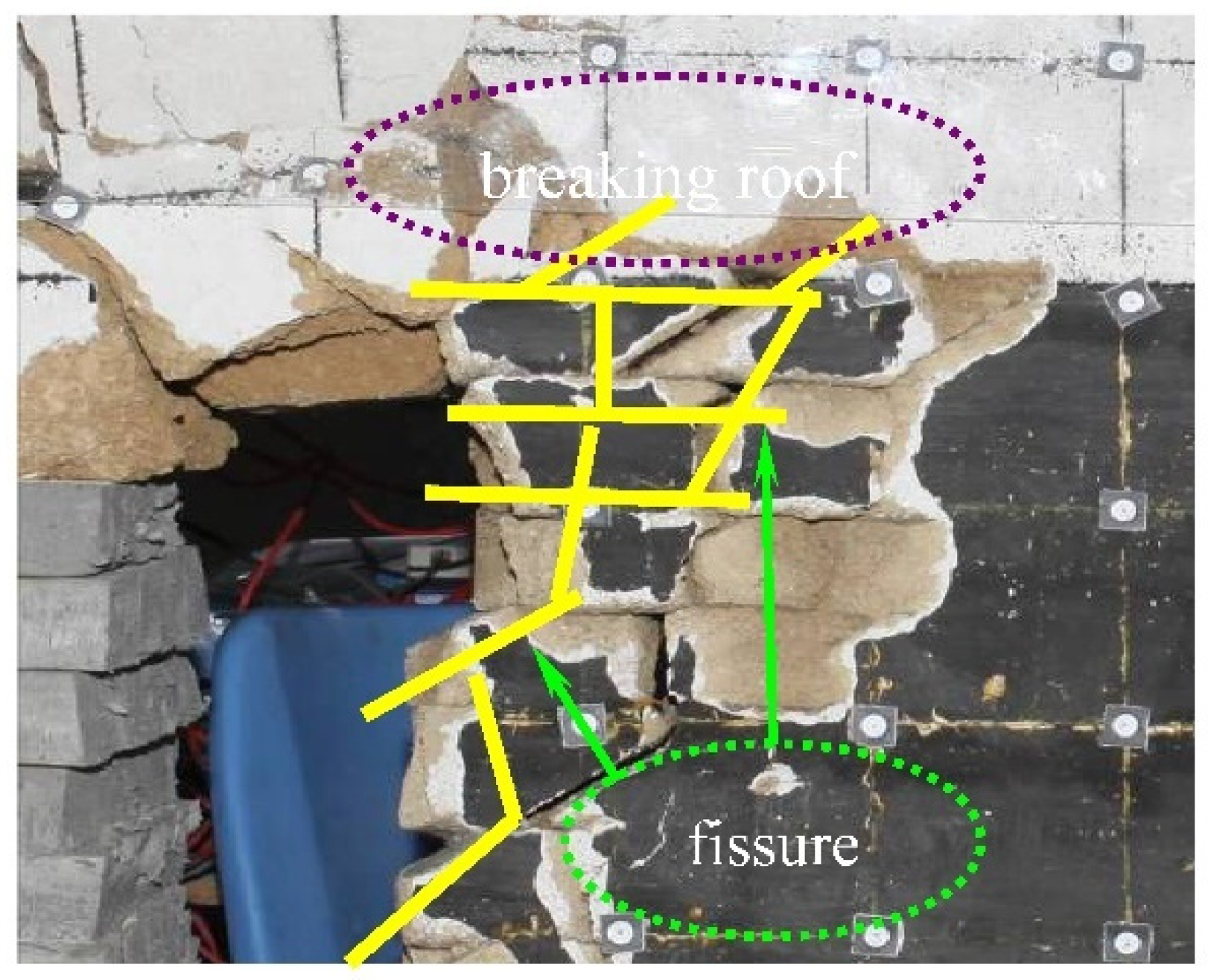
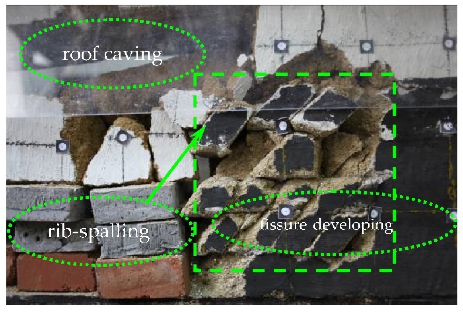
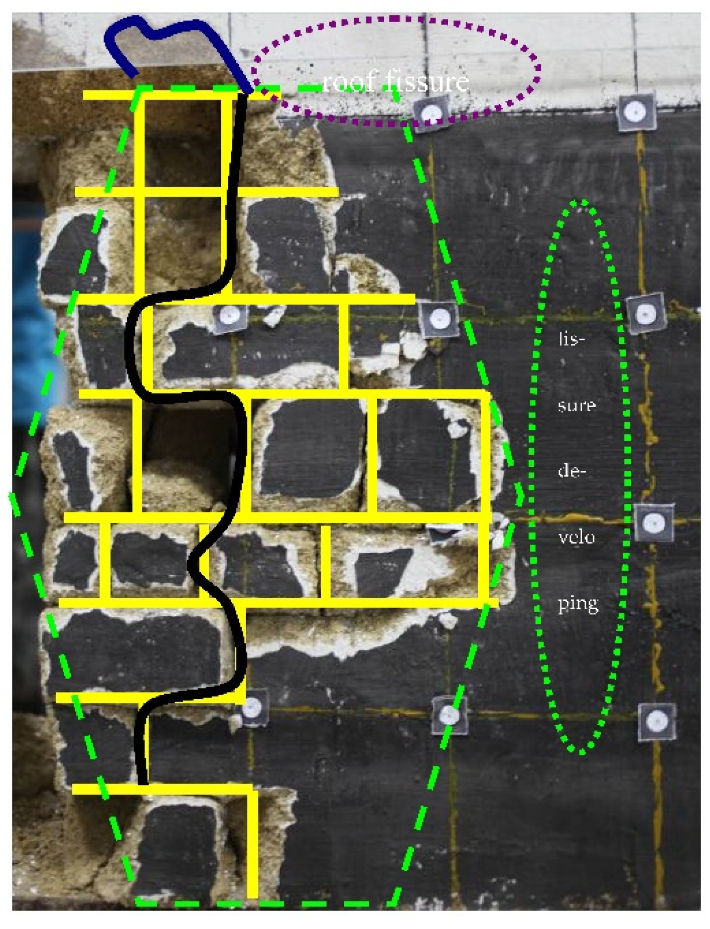
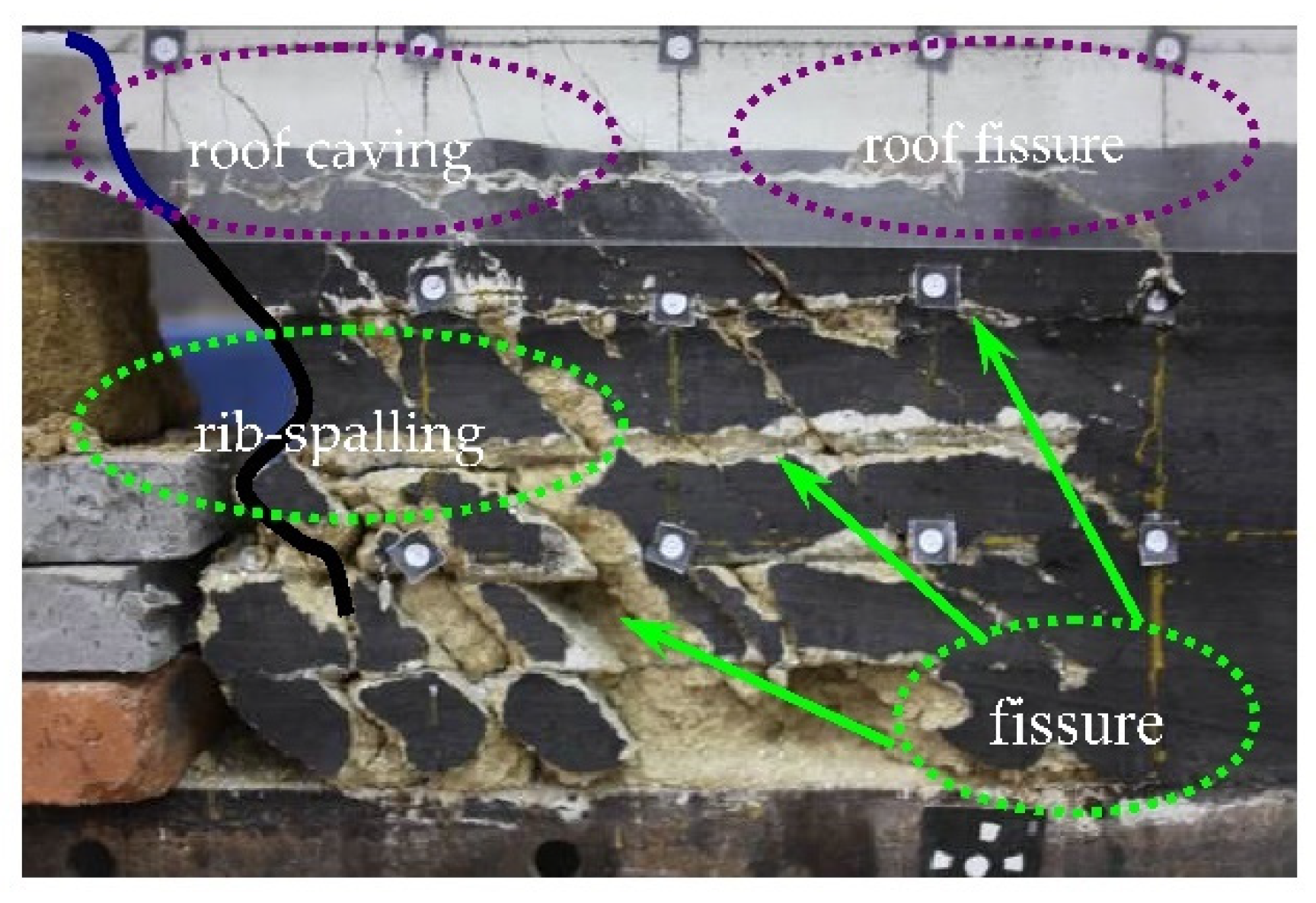
The experiments are based on the physical model laid out on the 4309 working faces of a mine, revealing the expansion and evolution law of the joint fissures and the instability of the rib-spalling in FHG under different joint surface inclination conditions. The form, size, and density of the expanding and penetrating joint fissures in the coal seam are mainly influenced by the occurrence of the primary joint surface, and the deformation and damage characteristics of the coal wall are the macroscopic expression of the expanding and evolving joint fissures. As a result of the expansion and penetration of the joint fissures, the coal wall is cut into a combination of diamond-shaped or vertical strips, and coal wall stability depends on the stability of these strips. At a macroscopic level, the morphology of the coal wall rib-spalling in FHG is mainly influenced by the developed joint fissure surface, and the height and depth of the rib-spalling are largely consistent with the extent of joint fissure extension and development.
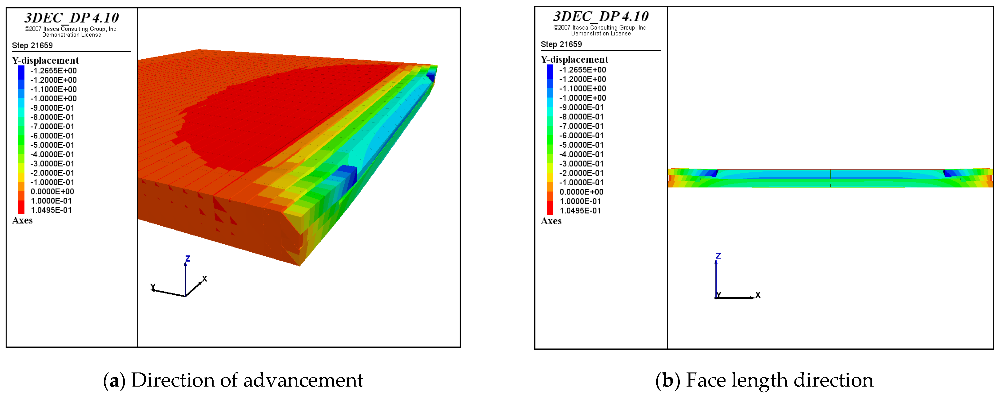
(2)
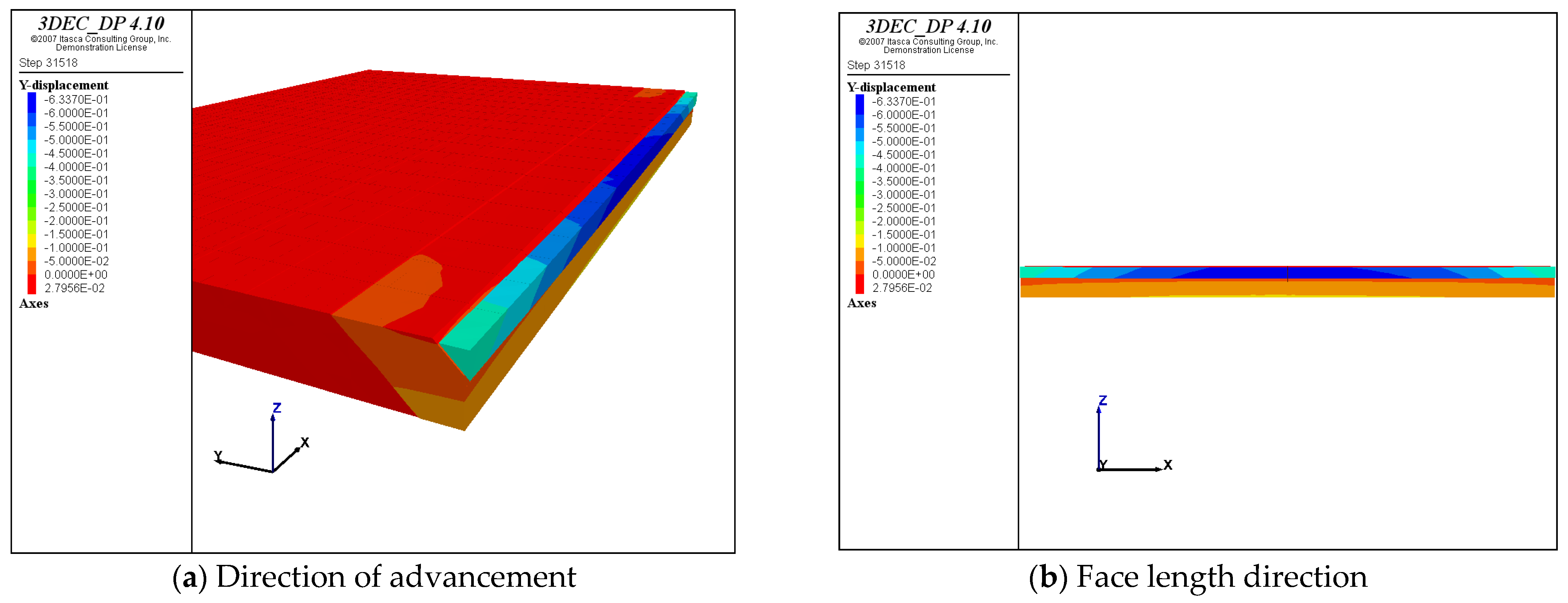
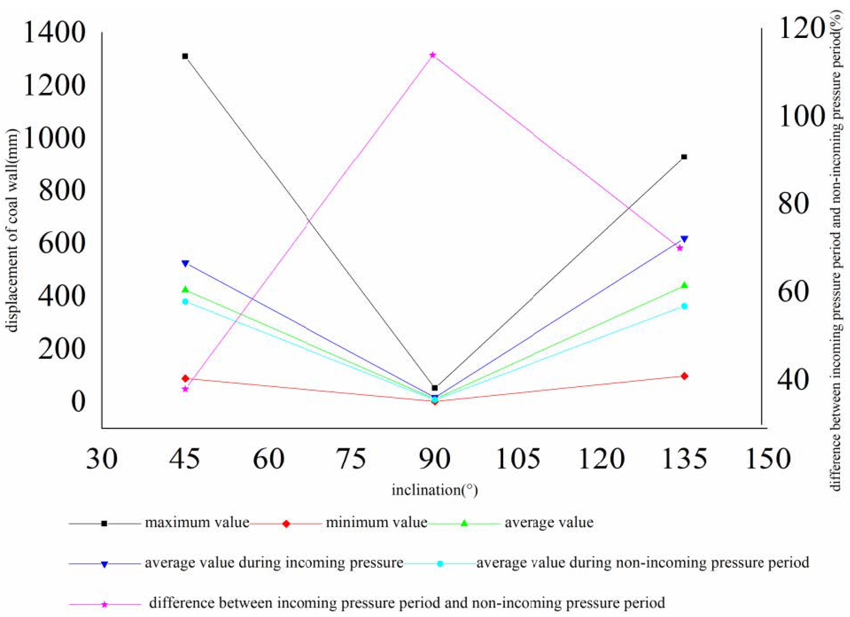
Using the 3DEC numerical calculation method, we revealed the spatial and temporal evolution laws of the distribution characteristics of coal wall displacement and deformation instability areas in FGH. Under hard coal conditions, when the inclination angle of the joint surface is 90°, the coal wall stability is better, and the middle and upper part of the face and the two ends of the area of the easy working face rib-spalling during the incoming pressure and non-incoming pressure periods, respectively. When the angle between the working face and the joint surface is acute, the local displacement of the coal wall is larger, and easy rib-spalling area of the working face is located above the intersection line between the joint surface and the working face. When the angle is obtuse, the easy rib-spalling area of the working face is located below the intersection line. Coal wall stability is worst when the hard coal and the angle of inclination of joint surface is 45°.
(3)
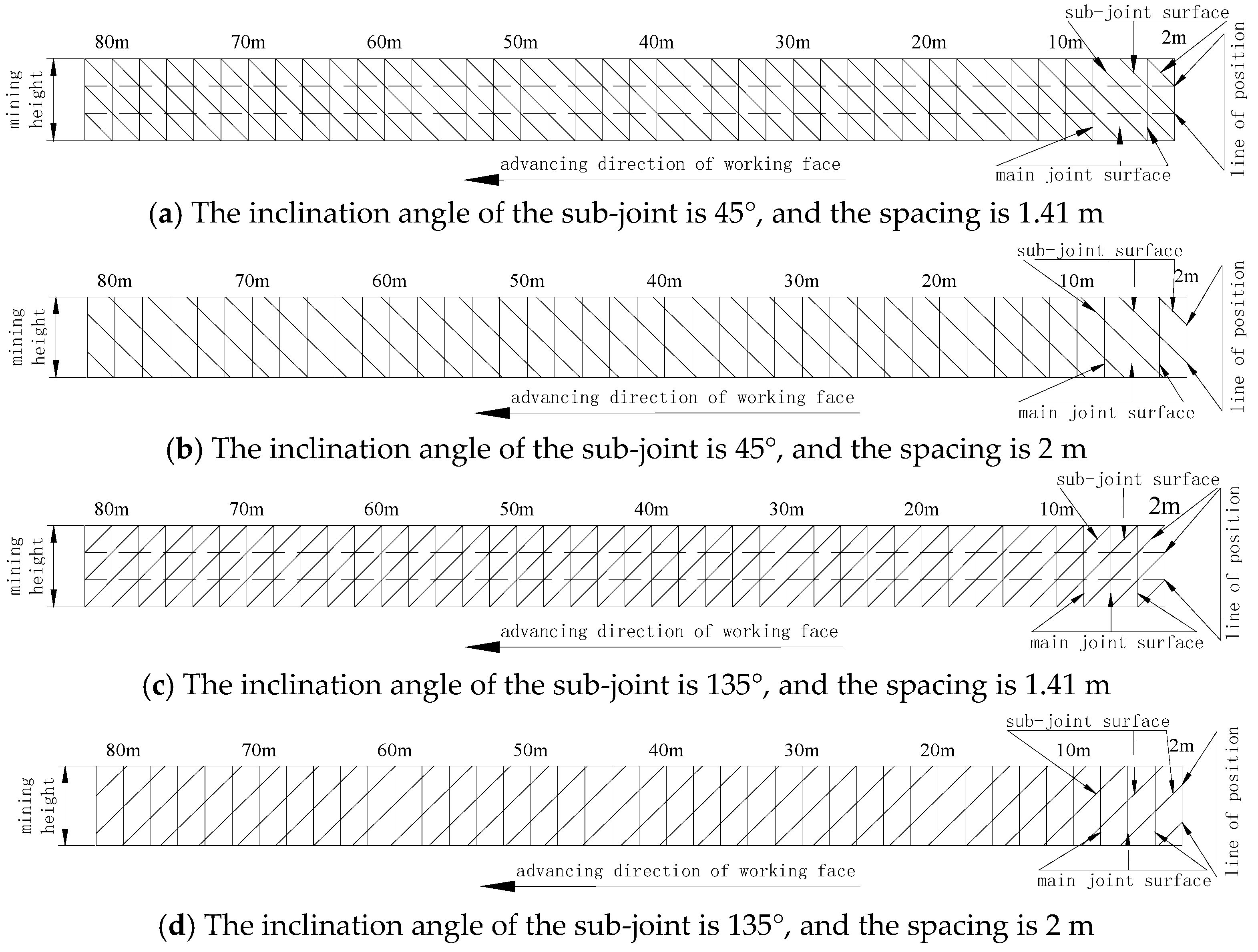
Under the conditions of medium-hard coal and joint surface inclination of 45° and 135°, the block size of the coal body at the working face cut by the joint surface is an important factor affecting coal wall stability; the smaller the spacing of the joint surface, the smaller the block size of the broken unit of the coal wall. The larger the area of the easy working face rib-spalling area, the worse the coal wall stability.
(4)
Under the condition of joint surface inclination on coal seam, the smaller the spacing between the joint surface, the less stable the coal wall is, and the working face pressure has relatively less influence on the coal wall stability. From the perspective of coal wall stability control, coal wall reinforcement technical measures such as advanced grouting, wood bolt, or FRP hollow grouting bolt should be considered to increase the spacing of coal seam joint surface, so as to ensure the coal wall stability.

Author Contributions

Conceptualization, W.G.; Methodology, Y.L.; Software, W.G.; Validation, Y.L.; Formal analysis, W.G.; Investigation, Y.L.; Resources, W.G.; Data curation, W.G.; Writing—original draft, W.G.; Writing—review & editing, Y.L. and G.W.; Visualization, G.W.; Supervision, Y.L.; Project administration, Y.L.; Funding acquisition, W.G. All authors have read and agreed to the published version of the manuscript.

Funding

This work was supported and financed by the National Natural Science Foundation of China (Grant no. 52004205, 51974231, 51604214, 51174192).

Data Availability Statement

All the data, models, and code generated or used during the study appear in the submitted article.

Conflicts of Interest

The authors declare that there are no conflict of interest regarding the publication of this paper.

References

  1. Pang, Y.; Wang, G.; Ren, H. Multi-factor sensitivity analysis of coal wall rib-spalling in FHG. J. Min. Saf. Eng. 2019, 36, 736–745. [Google Scholar]
  2. Ma, Z. Study on the coexistence mechanism of pull-shear damage of coal wall rib-spalling at FHG. Coal Sci. Technol. 2020, 48, 81–87. [Google Scholar]
  3. Yang, W. Study on the Mechanism of Coal Wall Rib-Spalling at the Working Face with the Large Inclination and Great Mining Height in the Roof of Coal Gangue Interlayer; Xi’an University of Science and Technology: Xi’an, China, 2020. [Google Scholar]
  4. Fu, Q.; Liu, M.; Zhang, M.; Yang, J.; Wang, H. Research on the technology of weak top coal to control coal wall rib-spalling in great mining height comprehensive release working face. China Coal 2018, 44, 46–51. [Google Scholar]
  5. Wang, G.; Pang, Y. Evaluation and technical principles of adaptability of large mining integrated release in extra-thick coal seams. J. Coal 2018, 43, 33–42. [Google Scholar] [CrossRef]
  6. Wu, Y.; Liu, K.; Liu, M.; Wang, H.; Luo, S.; Xie, P. Mining thickness effect on the stability of coal wall in long-walled great mining height working face in large inclined coal seam. J. Min. Saf. Eng. 2018, 35, 64–70. [Google Scholar]
  7. Xu, Y.; Wang, G.; Li, M.; Xu, Y.; Han, H.; Zhang, J. Characteristics of cracked and rib-spalling helpers in oversized mining workings and reasonable helper protection control. J. Coal 2021, 46, 357–369. [Google Scholar]
  8. Zhang, J.; Li, M.; Yang, Z.; Li, T.; Xu, Y.; Zeng, M.; Xin, J. Study on the mechanism of coal wall fragmentation and multi-dimensional protection measures in super high mining workings. J. Min. Saf. Eng. 2021, 38, 487–495. [Google Scholar]
  9. Liu, S.; Yang, K.; Tang, C. Mechanism and Integrated Control of “Rib Spalling: Roof Collapse-Support Instability” Hazard Chains in Steeply Dipping Soft Coal Seams. Adv. Mater. Sci. Eng. 2021, 2021, 5524591. [Google Scholar] [CrossRef]
  10. Si, L.; Wang, Z.; Liu, X.; Tan, C.; Anon, R. Assessment of rib spalling hazard degree in mining face based on background subtraction algorithm and support vector machine. Curr. Sci. 2019, 116, 2001–2012. [Google Scholar] [CrossRef]
  11. Guo, W.-B.; Liu, C.-Y.; Dong, G.-W.; Lv, W.-Y. Analytical study to estimate rib spalling extent and support requirements in thick seam mining. Arab. J. Geosci. 2019, 12, 276. [Google Scholar] [CrossRef]
  12. Zhu, W.; Li, J.; Chen, W. Damage Mechanism and Anchorage Effect of Jointed Rock Masses and Engineering Applications; Science Press: Beijing, China, 2002. [Google Scholar]
  13. Yang, H.-L.; Tian, Z.-L.; Zhang, L.-S.; Xiang, Z.-Y. Wellbore Stability Analysis of Coal Seam Based on Hoek-Brown Criterion. In Proceedings of the International Conference on Manufacturing Science and Technology (ICMST 2011), Singapore, 16–18 September 2011; pp. 3882–3888. [Google Scholar]
  14. Wu, Y.; Zhang, Z.; Wang, X.; Zhu, P.; Yang, X.; Jiang, L. Study on the Physical Properties and Joint Evolution Characteristics of Three-Dimensional Reconstructed Coal. Adv. Mater. Sci. Eng. 2021, 2021, 7038110. [Google Scholar] [CrossRef]
  15. Jiang, Y.D.; Zhao, Y.X.; Liu, W.G. Numerical simulation of coal seam joints and stiffness effects on coal bumps. In Proceedings of the 5th International Symposium on Mining Science and Technology (ISMST), Xuzhou, China, 20–22 October 2004; pp. 459–462. [Google Scholar]
  16. Guo, W.; Zhang, S.; Li, Y. The Effect of Joint Damage on a Coal Wall and the Influence of Joints on the Abutment Pressure on a Fully Mechanised Working Face with Large Mining Height. Shock Vib. 2021, 2021, 9963175. [Google Scholar] [CrossRef]
  17. Wang, Z.; Xu, D.; Chen, X. Application Study on “Boreholes-Wall” Joint Excavation and Drainage Technology. In Proceedings of the International Symposium on Safety Science and Technology, Beijing, China, 24–27 September 2008; pp. 1451–1455. [Google Scholar]
  18. Lan, H. Ontogenetic Model of Mining Damage in Jointed Rock and Its Application in Open-Hole Joint Mining Project; General Research Institute of Coal Science: Beijing, China, 2007. [Google Scholar]
  19. Li, J.; Zhu, W. Research on the fracture damage mechanism of intermittently jointed rock masses under complex stresses and its application. J. Rock Mech. Eng. 1999, 18, 142–146. [Google Scholar]
  20. Hua, X.; Xie, G. Mechanism and control technology of coal wall rib-spalling at FHG. Coal Sci. Technol. 2008, 36, 1–3, 24. [Google Scholar]
  21. Guo, B.; Tu, M. A brief introduction to great mining height integrated mining technology in China. China Min. 2003, 12, 41–43. [Google Scholar]
  22. Fang, X.Q.; He, J.; Li, H.C. Study on the mechanism and prevention of coal wall rib-spalling at soft coal heaving face. J. China Univ. Min. Technol. 2009, 38, 640–644. [Google Scholar]
  23. Liu, H.; Liu, W. Study on the influence of coal wall rib-spalling on coal mining working face. Coal Technol. 2006, 25, 136–137. [Google Scholar]
  24. Li, J. Mineral pressure observation and roof management at FHG. J. North China Inst. Sci. Technol. 2004, 1, 10–12. [Google Scholar]
  25. Ning, J.G.; Liu, X.S.; Tan, J.; Gu, Q.H.; Tan, Y.L.; Wang, J. Control mechanisms and design for a ‘coal-backfill-gangue’ support system for coal mine gob-side entry retaining. Int. J. Oil Gas Coal Technol. 2018, 18, 444–466. [Google Scholar] [CrossRef]
  26. Yang, S.; Yue, H.; Zhai, R.; Cui, Z.; Wei, X. 3D Physical Experimental Study of Shield-Strata Interaction Under Dynamic and Static Disturbance. Front. Earth Sci. 2022, 10, 913903. [Google Scholar] [CrossRef]
  27. Dychkovskyi, R.; Shavarskyi, I.; Saik, P.; Lozynskyi, V.; Falshtynskyi, V.; Cabana, E. Research into stress-strain state of the rock mass condition in the process of the operation of double-unit longwalls. Min. Miner. Depos. 2020, 14, 85–94. [Google Scholar] [CrossRef]
  28. Vu, T.T. Solutions to prevent face spall and roof falling in fully mechanized longwall at underground mines, Vietnam. Min. Miner. Depos. 2022, 16, 127–134. [Google Scholar] [CrossRef]
  29. Li, Z.; Hua, X.; Yang, K.; Zhu, R.; Zhou, D. Numerical analysis of influencing factors of stability in thick coal seam mining roadway. In Proceedings of the 2nd International Conference on Civil Engineering and Transportation (ICCET 2012), Guilin, China, 27–28 October 2012; pp. 1453–1457. [Google Scholar]
  30. Cheng, L.; Zhang, Y. A New Closed-Form Solution of the Side Abutment Pressure Distribution of Roadway. Adv. Civ. Eng. 2018, 2018, 1409493. [Google Scholar] [CrossRef] [Green Version]
  31. Qian, M.; Shi, P. My Pressure and Rock Control; China University of Mining and Technology Press: Xuzhou, China, 2003. [Google Scholar]
  32. Cai, M.; He, M.; Liu, D. Rock Mechanics and Engineering; Science Press: Beijing, China, 2002. [Google Scholar]
  33. Yang, P.; Liu, C.; Wu, F. Damage law and destabilization mechanism of coal wall in great mining height quarry with thick coal seam. J. China Univ. Min. Technol. 2012, 41, 371–377. [Google Scholar]
  34. Yang, S.; Zhao, B.; Li, L. Mechanism of coal wall damage in pseudo-spacing towards longwall working face of sharply inclined coal seam. J. Coal 2019, 44, 367–376. [Google Scholar]
  35. Fu, B.; Tu, M.; Gao, M. Research on unloading instability model of coal wall at great mining height working face. J. Min. Saf. Eng. 2017, 34, 1128–1133. [Google Scholar]
  36. Lou, J.; Kang, H.; Li, J.; Yang, J.; Gao, F. Study on the working resistance of great mining height bracket based on the comprehensive evaluation of “Roof—Coal Wall—Bracket”. J. Coal 2017, 42, 2808–2816. [Google Scholar]
  37. Luo, S.; Wu, Y.; Liu, K.; Xie, P.; Wang, H. Characteristics of asymmetrically loaded instability of coal wall in large inclination angle and great mining height comprehensive mining working face. J. Coal 2018, 43, 1829–1836. [Google Scholar]
  38. Wang, Z.; Wang, J.; Yang, Y.; Tang, Y.; Wang, L. Analysis of brace stiffness effect on coal wall stability in header mining working face. J. China Univ. Min. Technol. 2019, 48, 258–267. [Google Scholar]
  39. Cui, S.-J.; Zhu, J.-M. Study on the Key Technology of Coal Wall Stability Control for Mining All Height at One Time in Thick Seam. In Proceedings of the International Conference on Mechanics and Civil Engineering (ICMCE), Wuhan, China, 13–14 December 2014; pp. 757–763. [Google Scholar]
  40. Yuan, A.; Hu, H.; Yuan, Q. A Study of the Laws of Abnormal Gas Emissions and the Stability Controls for Coal Mine Walls in Deeply Buried High-Gas Coal Seams. Adv. Civ. Eng. 2020, 2020, 8894854. [Google Scholar] [CrossRef]
  41. Liu, H.; Ju, C.-L.; He, G.; Zhang, W.; Jiang, W.; Lv, K. The Safe Stability Research of the Buttock FRP Bolt Supporting. In Proceedings of the 2nd China Energy Scientist Forum, Xuzhou, China, 18–19 October 2010; pp. 305–308. [Google Scholar]
  42. Bai, Q.-S.; Tu, S.-H.; Chen, M.; Zhang, C. Numerical modeling of coal wall spall in a longwall face. Int. J. Rock Mech. Min. Sci. 2016, 88, 242–253. [Google Scholar] [CrossRef]
  43. Yuan, Y.; Tu, S.; Zhang, X.; Liu, A. Mechanism and Control Technique of Rib Spalling Disaster in Fully-mechanized Mining with Large Mining Height in Soft Coal Seam Face. Disaster Adv. 2013, 6, 92–98. [Google Scholar]
  44. Li, L.; Zhang, F. Instability Model of a Coal Wall with Large Mining Height under Excavation Unloading Conditions. Adv. Civ. Eng. 2020, 2020, 8863602. [Google Scholar] [CrossRef]
  45. Li, H. Similar Simulation Tests of Mine Pressure; China University of Mining and Technology Press: Xuzhou, China, 1988. [Google Scholar]
  46. Wang, H. Research on Creep Characteristics of Narrow Gangs along Hollow Roadways and Its Stability Control Technology; China University of Mining and Technology: Xuzhou, China, 2011. [Google Scholar]
  47. Lin, Y. Experimental Rock Mechanics Simulation Studies; Coal Industry Press: Beijing, China, 1984. [Google Scholar]
  48. Zhou, Z.; Cao, P.; Lin, H. Selection of mechanical parameters for jointed rock in 3DEC applications. West. Prospect. Eng. 2006, 07, 163–165. [Google Scholar]
  49. Itasca International Company. 3-Dimensional Distinct Element Code Manual; An Itasca International Company: Minneapolis, MN, USA, 2007. [Google Scholar]
Figure 1. Strata histogram of 4309 working face.
Energies 15 09059 g001
Figure 2. Experiment model of the two-dimensional plane stress.
Energies 15 09059 g002
Figure 3. Precast block size of main roof.
Energies 15 09059 g003
Figure 4. Sketch of physical model.
Energies 15 09059 g004
Figure 5. 3DEC numerical simulation model.
Energies 15 09059 g005
Figure 6. Model section of joint surfaces with different inclination angles in hard coal seam (the dotted line is the excavation step).
Energies 15 09059 g006
Figure 7. Model section of joint surfaces with different spacings in medium-hard coal seam.
Energies 15 09059 g007
Figure 8. Development of joint and instability form the coal wall rib-spalling (α = 30°).
Energies 15 09059 g008
Figure 9. Development of joint and instability form the coal wall rib-spalling (α = 60°).
Energies 15 09059 g009
Figure 10. Development of joint and instability form the coal wall rib-spalling (α = 90°, non-through seam).
Energies 15 09059 g010
Figure 11. Development of joint and instability form the coal wall rib-spalling (α = 90°, through seam).
Energies 15 09059 g011
Figure 12. Development of joint and instability form the coal wall rib-spalling (α = 120°).
Energies 15 09059 g012
Figure 13. Development of joint and instability form the coal wall rib-spalling (α = 150°).
Energies 15 09059 g013
Figure 14. Y-displacement nephogram (α = 45°).
Energies 15 09059 g014
Figure 15. Y-displacement nephogram (α = 90°).
Energies 15 09059 g015
Figure 16. Y-displacement nephogram (α = 135°).
Energies 15 09059 g016
Figure 17. Coal wall Y-displacement change law with the joint inclination angle.
Energies 15 09059 g017
Figure 18. Y-displacement nephogram (αsj= 45°, d = 1.41 m).
Energies 15 09059 g018
Figure 19. Y-displacement nephogram (αsj = 45°, d = 2 m).
Energies 15 09059 g019
Figure 20. Coal wall Y-displacement change law with joint spacing (α = 45°).
Energies 15 09059 g020
Figure 21. Y-displacement nephogram (αsj = 135, d = 1.41 m).
Energies 15 09059 g021
Figure 22. Y-displacement nephogram (αsj = 135°, d = 2 m).
Energies 15 09059 g022
Figure 23. Coal wall Y-displacement change law with joint spacing (α = 135°).
Energies 15 09059 g023
Table 1. Thickness and mechanical parameters of different strata.
LithologyThickness (m)Density (kg/m3)Compressive Strength (MPa)Tensile Strength (MPa)
Siltstone4276052.44.2
Sandy mudstone12.58275035.51.73
3# Coal7 (4.5)1400203
Table 2. Thickness and mechanical parameters of physical model.
LithologyThickness (mm)Density (kg/m3)Compressive Strength (MPa)Tensile Strength (MPa)
Siltstone2301652.71.80.1
Sandy mudstone7001646.71.20.1
3# Coal400 (250)838.30.70.1
Table 3. Material ratio of physical model.
Rock stratumThickness (mm)Stratification Quality (kg)Water (kg)Sand (kg)Calcium Carbonate (kg)Gypsum (kg)Remarks
Main roof230209.120.9167.310.510.5Making blocks
Immediate roof700634.063.4513.517.139.9Layered laying
Medium hard coal250115.311.593.45.25.2
400184.418.4149.48.38.3
Table 4. Mechanical parameters of coal seam joint surface.
Normal Stiffness
(GPa)
Tangential Stiffness (GPa)Cohesion
(MPa)
Internal Friction Angle (°)Tensile Strength (MPa)
3.81.50~4150
Table 5. Mechanical parameters of coal and rock.
Serial NumberLithologyBulk Density (kg·m−3)Bulk Modulus
(GPa)
Shear Modulus
(Pa)
Internal Friction Angle
(°)
Cohesion
(MPa)
Tensile Strength
(MPa)
1fine sandstone27501917.4454015
2siltstone275021.419.630302.4
3sandy mudstone250013.310466.88
4siltstone275021.419.630302.4
5sandy mudstone250013.310466.88
63# coal14005~16.72.3~7.7301~82~4
7sandy mudstone250013.310466.88
Table 6. Occurrences of joint surfaces with different inclination angles in hard coal seam.
NumberingCoal Body PropertiesJoint PropertiesJoint Parameters
Inclination (°)Spacing (m)
1hard coalmain joint surface455
290
3135
Table 7. Occurrences of joint surfaces with different spacings in medium-hard coal seam.
NumberingJoint PropertiesJoint Parameters
Inclination (°)Spacing (m)
1main joint surface902
sub-joint surface45
2main joint surface902
sub-joint surface451.41
3main joint surface902
sub-joint surface135
4main joint surface902
sub-joint surface1351.41
Table 8. Coal wall Y-displacement at different joint inclination angles.
Coal PropertiesNumber of Joint SurfacesJoint Surface ParametersMax (mm)Min (mm)Average (mm)Incoming Pressure Average (mm)Non-Incoming Pressure Average (mm)Difference Value
Hard coalA set of main joint surfaces, d = 5 mα = 45°13108942452638038%
α = 90°522.411.0317.68.23114%
α = 135°9289844061936370%
Table 9. Coal wall Y-displacement in different joint spacings (α = 45°).
Coal PropertiesNumber of Joint SurfacesJoint Surface ParametersMax
(mm)
Min
(mm)
Average
(mm)
Incoming Pressure Average (mm)Non-Incoming Pressure Average (mm)Difference Value
Hard coalA set of main joint surfaces, d = 5 mα = 45°13108942452638038%
Medium hard coalA group of main joint surfaces and a group of secondary joint surfaces. Parameters of main joint surfaces: α= 90°d = 2 mα = 45°,
d = 1.41 m
237641210791219101820%
α = 45°,
d = 2 m
2318261962138877978%
Table 10. Coal wall Y-displacement in different joint spacing (α = 135°).
Coal PropertiesNumber of Joint SurfacesJoint Surface ParametersMax
(mm)
Min
(mm)
Average
(mm)
Incoming Pressure Average (mm)Non-Incoming Pressure Average (mm)Difference Value
Hard coalA set of main joint surfaces, d = 5 mα = 135°9289844061936370%
Medium hard coalA group of main joint surfaces and a group of secondary joint surfaces. Parameters of main joint surfaces: α= 90°, d = 2 mα = 135°,
d = 1.41 m
232454911251316104326%
α = 135°,
d = 2 m
29153861081142293552%
Publisher’s Note: MDPI stays neutral with regard to jurisdictional claims in published maps and institutional affiliations.

