Abstract
The article presents a method for detecting earth faults in a compensated medium-voltage network, which can be used especially in fault current passage indicators, but also in standard protection devices. The method is based on the adaptation process of the zero-sequence current protection setting, with the adaptation factor depending on the current value of the zero-sequence voltage. In this article, a comparative analysis of the classical and adaptive zero-sequence current criterion is conducted, taking into account the errors of the measuring system. The results of simulations performed in the PSCad environment are also presented. For a representative set of example short circuits, it was shown that the effectiveness of the presented criterion can be more than 50% higher than that of the standard criteria, taking into account the range of detected transition resistances. A comparison of the proposed method with admittance criteria was also drawn, and it was shown that it is suitable for the detection of high-resistance earth faults.
1. Introduction
Nearly 90% of all power outages to consumers come from medium-voltage (MV) networks [1]. In modern MV networks, about 75% of all faults are earth faults [2,3,4,5]. Of all earth faults, 85% are self-extinguishing ones [6].
Methods for locating earth faults in medium-voltage networks can be divided into two main groups: centralized and decentralized. In centralized methods, the necessary measurements are made at the high-voltage/medium-voltage (HV/MV) substation and the decision is made there. In decentralized methods, measurements are made by measuring devices scattered along the medium-voltage line, so it is necessary to ensure communication between them and the supervisory system.
Centralized methods for detection and localization of earth faults include impedance-based, artificial intelligence-based, and waveform-based methods.
In impedance-based methods, the grea test difficulty is estimating the impedance of the short-circuit loop and determining the unit impedance of the line. Many attempts have been made to solve this problem, which are described, for example, in [7,8,9,10]. The paper [11] compares ten different ways of determining the short-circuit loop impedance. A detailed description of the algorithm for the detection of earth faults in a compensated network based on impedance measurement is described in the paper [12]. The method, which is based on a series of equations, has been verified in practice and its efficiency has been proved to be high enough (for short circuits with ) to be implemented in selected ABB IED.
Methods based on artificial intelligence are quite widely described in the literature, and most of them are based on neural networks [13,14,15,16,17]. Methods using artificial intelligence can be very advantageous for use in networks with a high degree of complexity. The article in [14], which presents the possibility of extending the functionality of the fault detection system to include the precise location of the fault location, is noteworthy for proposing new neural network learning algorithms. Due to the computational complexity of the presented methods, their usefulness in practice, in our opinion, is rather questionable. In practice, it is difficult to find real implementations of devices and systems that would use artificial intelligence to locate short circuits. There is also little evidence of actual AI implementation in the numerous scientific articles related to this topic. Moreover, it should be noted that the number of research papers on these methods is decreasing year by year. However, this does not change the fact that the methods are very promising and may find wide application in the near future.
Regarding localization and detection using wave methods, the work in [18] reports five different types of wave locator, only some of which can be used for medium-voltage networks. Wave methods are mainly intended for use in transmission networks, but the works [19,20,21,22,23] discuss attempts to apply wave methods to locate faults in MV networks. However, the conclusions emphasize the main problem—due to the significant branching of this type of network, wave reflections can come from various sources, not only from the fault location. This makes it virtually impossible to apply these methods to an actual network. Nevertheless, they suggest that a very effective method based on wave theory is possible for some specific, unbranched network systems which may be developed.
Today’s MV grid is characterized by a certain, relatively high (although this depends on the country), saturation with smart grid devices, which can include bay terminals (IED) and reclosers, fault current passage indicators (FCPI) or smart electricity meters (AMI). For example, Canada will invest CAD 960 million in the near future in smart grid development. In China, up to 80% of meters will be of the AMI type, while the US goal is to reach 100% AMI meters in the near future. Germany will have more than 44 million AMIs in operation by 2026 [24]. In Poland, grid saturation with smart grid devices is, for the time being, low, but very large projects are underway to change this state of affairs. By 2027, there will be about 70% of AMI meters, there are already about 12–15 (depending on the region) reclosers for every 100 km of line.
The introduction of these devices into service has led to the proposal of decentralized fault detection methods, especially earth faults. Their idea is that localization is performed not on the basis of signals from a single measuring point (usually a line/feeder bay) but on the basis of measurements carried out at multiple locations on a given network.
Short-circuit localization in MV networks based on measurements made by smart electricity meters (AMI) is mainly based on the analysis of voltage asymmetry on the low-voltage side of transformers distributed along MV lines. Such an approach is presented in [25,26,27].
The most important role in the localization process is played by FCPIs, which are able to detect a fault and send an appropriate signal about its occurrence to the supervision system. Improvements in the reliability of network operation depend directly on the location of FCPIs, while reliability indices increase linearly (to the asymptote) as their number increases [28].
It should be noted that a separate problem is the detection of permanent short circuits (relevant to this article) and intermittent faults [29].
The basic idea of decentralized fault detection and localization is shown in Figure 1.
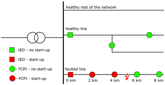
Figure 1.
The idea of decentralized localization of a fault location in an MV network using FCPI as an example.
The key aspect of fault localization, therefore, remains not so much the identification of where the short has occurred, but its effective identification.
Standard methods for detecting Earth faults by FCPI, based solely on measuring the zero-sequence current or admittance criteria, are sometimes unreliable and ineffective during high-resistance faults, that is, those in which the transition resistance at the fault point is greater than . This article presents a method for earth fault detection in a compensated medium-voltage network that can be applied to FCPI, which uses the idea of adapting the current setting of the earth fault criterion. The adaptation process uses the value of the zero-sequence voltage, which should be measured at the FCPI site, and simplified methods can be used here, as presented, for example, in [30].
The article is organized as follows. Section 2 presents an analysis of the effectiveness of earth fault detection by FCPIs, which are based on the zero-sequence current criterion. In particular, compensated networks were considered. Section 3 details the idea of the zero-sequence current adaptive criterion. Section 4 shows the results of simulation studies of adaptive protection conducted in the PSCad environment. Section 5 summarizes the entire article.
2. Efficiency of the Zero-Sequence Current Criterion in the Detection of Earth Faults
2.1. General Informations
In this article, “efficiency” will refer to the ratio of the number of correctly identified earth faults to all the faults that can occur in a given network. The main factor differentiating individual faults is the resistance of the transition between the phase conductor and ground .
In order to analyze the effectiveness of the zero-sequence current criterion in the detection of earth faults in the MV network by fault current passage indicators, it is necessary to calculate the characteristic quantities related to the earth fault current.
The most common relationships that describe the values of the earth fault current in MV networks with ineffectively earthed neutral points do not take into account the longitudinal impedances of the components of the power system [31,32]. Although such a procedure is not fully justified, these relationships ensure sufficient accuracy and can be used successfully to calculate the settings of various types of protection. The relationships that ignore longitudinal impedances are presented in the following formulas [33,34]:
where —zero-sequence voltage, —earth fault coefficient, —phase-to-earth voltage, —current at fault location, —network ground capacity (equivalent), —damping decrement of the network, s—earth fault compensation detuning coefficient.
The earth fault coefficient can be calculated from the following relationship:
where —transition resistance between the phase conductor and the earth at the fault location, —voltage pulsation.
Damping decrement of the network can be calculated using the formula:
where —network ground conductance, —earthing coil conductance, —resistance in the neutral point of the network, —active current in the neutral point during a metallic earth fault, —capacitive current of a network.
The nominal value of the earth fault current of the earthing resistor (in the network with the neutral point earthed by the resistor, several hundred amps) or, for compensated networks, the value of the current forced on the primary side by the Active Current Forcing Automation (ACFA, several amps) system can be assumed to be .
The detuning coefficient s is given by the formula:
where —rated earth fault current of the compensating coil.
The value of the earth fault current flowing through a given point of the line (e.g., the place of installation of the protection, recloser, or fault current passage indicator) can be calculated according to the formula:
where a—the relative value of the capacitive current of the entire line in the capacitive current of the network , i.e., .
The value of the earth fault current flowing through the current transformer (CT) installed at the beginning of the line (in the switchgear) can be calculated according to the formula:
where —the relative value of the share of the capacitive current behind the considered point in the capacitive current of the network (see Figure 2), i.e.,
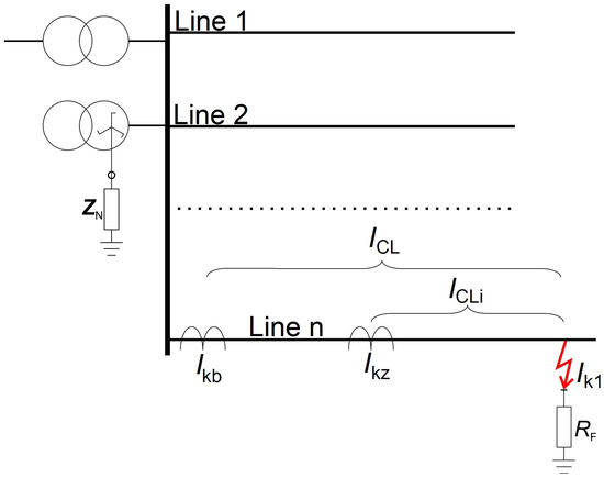
Figure 2.
Earth fault current at the fault location and at selected points on the line.
Formulas (1)–(8) are universal and can be used in a compensated network as well as in a network with a resistor-earthed neutral point. In the latter case, should be assumed.
To assess the effectiveness of the zero-sequence current criterion, the earth fault protection setting should be calculated from the formula:
where —safety factor, assumed equal to 2, —return ratio, assumed in the range 0.85–0.98, here 0.98, —current error of the zero-sequence current filter.
The zero-sequence current criterion setting must also meet the second condition:
where is the protection sensitivity factor, which for the selected setting should be greater than 1.5 and preferably greater than 2.
Problems with the proper selection of the current setting of the zero-sequence current criterion result mainly from the fact that these criteria, in systems with FCPI, obtain signals from atypical filters. These can be three series-connected Rogowski coils, three current transformers with ongoing construction (in silicone insulation) [35]. There are also other non-standard solutions, such as measurement coils made with PCB HDI technology [36].
The value of the current error of the zero-sequence current filter, depending on Formulas (9) and (10), should be given on the primary side of the filter, because the FCPI current setting is calculated on the primary side. Currently, it can be assumed that the value of this error (for the Holmgreen filter) is equal to = 0.5 A [37]. It is stated in [38] that this value is higher for non-standard zero-sequence current filters. However, in a further analysis, it will assume the value of = 0.5 A in the hope that it is correct and certainly taking into account the continuous development and improvement of the quality of the measuring instruments.
2.2. Compensated MV Network with ACFA
For the analysis of the operation of FCPI in the compensated network with active current forcing automation, it was assumed that the capacitive current value of the network will be equal to = 120 A, which is a typical value for European medium-voltage networks (especially Polish). The optimal value of the induction current of the compensating coil should be in the range [34,37,39,40]:
Another relationship can also be assumed, which is as follows:
where is a self-extinguishing current limit. The value of the current for the MV network is quoted in various publications, and practically each one mentions a different one. Some publications [41] indicate that the self-extinguishing arc current in the MV network is greater than the values given in Table 1.

Table 1.
Values of self-extinguishing current limit.
Implementing the assumption given by Formula (11) indicates that for typical values of the network capacitance current , the values given in [37] can be taken as the most correct and safe.
As a result of Formula (11), = 132 A was assumed. For such a network, the value of the detuning factor is s = 0.1. It was also assumed that the system works with the active current forcing automation, with = 20 A. In this case, the damping decrement of the network is equal to = 0.167. Nominal network voltage = 15 kV.
Table 2 shows the values of the earth fault coefficients for different values of the transition resistance and the network with the assumptions as above.
Table 2.
Values of the earth fault coefficients and their modulus for various in the compensated MV network.
Table 3 presents the calculated values of the earth fault current in place of the protection installation. Their values, similar to those of a network grounded through a resistor, were calculated according to Equation (6). Different values of the line capacitance behind the protection installation site are assumed. The table also shows the values of the factor.
Table 3.
Calculated values of the earth fault current in place of the protection installation.
The minimum value of the zero-sequence current protection setting in the compensated network is calculated from Formula (9). Additionally, the second condition must also be checked:
Based on Formulas (9) and (13), the settings of the zero-sequence current criterion for the compensated network were determined. They are presented in Table 4. The value of the sensitivity factor is also included there.
Table 4.
Current settings and the corresponding sensitivity factors—compensated network.
Figure 3 shows the values of the earth fault current at the FCPI installation site for different values of the transition resistance at the fault location. They are compared to the setting values. The intersection of the lines in the graphs shows the value of , above which the classically zero current criterion will not work.
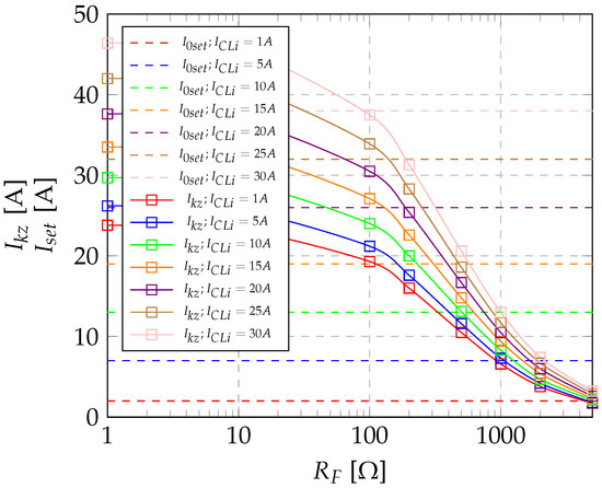
Figure 3.
The values of the and currents in the compensated network for different values of .
The maximum values of the transition resistance at the fault location during single phase earth faults in the compensated network with the parameters set previously are, for different values of , shown in Figure 4 and equal to:
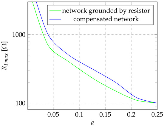
Figure 4.
Maximum values of , the occurrence of which causes the tripping of the classic zero-sequence current criterion in the network with the neutral point grounded by a resistor and the compensated network with the given parameters.
- For = 1 A − = 4.5 k;
- For = 5 A − = 1000 ;
- For = 10 A − = 500 ;
- For = 15 A − = 300 ;
- For = 20 A − = 200 ;
- For = 25 A − = 120 ;
- For = 30 A − = 100 .
Figure 5 shows the values of the maximum detected transition resistances for different values of the detuning factor s. From the point of view of the efficiency of detecting earth faults by the FCPI, the correct value of the detuning factor s is very important, i.e., the Petersen coil should be selected for a given network with current according to the dependence (11). Any short circuit can be detected in a perfectly compensated network (that is, ) only on lines whose , that is, in the case considered A. In noncompensated networks, short-circuit current flow indicators (and protections) based on the zero-sequence current criterion will operate only in specific cases of short-circuits with very low transition resistances. It is worth mentioning here that the analyses are conducted for the minimum possible setting, i.e., the maximum sensitivity factor. Increasing the setting, and thus reducing the sensitivity, will reduce the effectiveness of the criterion.
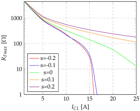
Figure 5.
Maximum detected values of transition resistance for the compensated network with a different value of the coefficient s.
3. Adaptive Zero-Sequence Current Criterion for the Compensated MV Network
A flowchart of adaptive zero-sequence current criterion for earth fault detection in compensated MV network is shown in Figure 6.
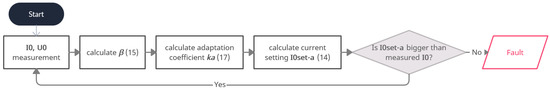
Figure 6.
Flowchart of adaptive zero-sequence current criterion.
In the case of a compensated network, an adaptation of the earth fault criterion can be applied, in which the adaptation coefficient depends on the value of the earth fault coefficient (see Table 2). The setting of the adaptation criterion should be selected according to the dependence:
The sensitivity of the adaptation criterion can be checked from the classic condition determined by Equation (13).
The value of the criterion to determine the adaptation coefficient is the value of the earth fault coefficient . The value of can be calculated from a sufficient formula:
where —RMS value of zero-sequence voltage during an earth fault, —maximum RMS value of zero-sequence voltage during a metallic earth fault in a given network.
The maximum value of the zero-sequence voltage during a metallic earth fault is equal to the nominal value of the phase-to-earth voltage , that is:
The value of the adaptation coefficient should be determined from the dependence:
where —value of the capacitive current of the i-th line section after installation of FCPI, —error (noise) of the zero-sequence current filter.
Table 5 presents the values of the zero-sequence voltage module for the compensated network as in Section 2.2. Furthermore, the calculated values of on the primary side of the zero-sequence voltage filter as a function of the transition resistance are shown in Figure 7.
Table 5.
Values of zero-sequence voltage measured in the compensated network with the previously mentioned parameters with = 15 kV for various transition resistances.
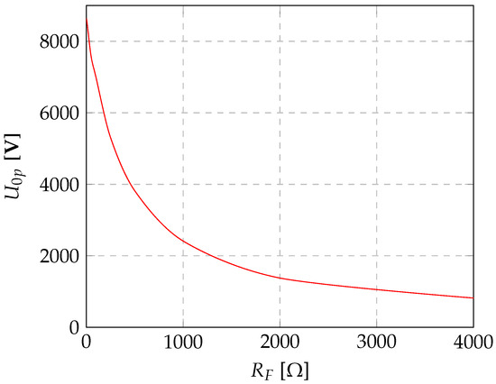
Figure 7.
RMS values of zero-sequence voltage in the network with the neutral point grounded by the resistor and in the compensated network as a function of the transition resistance.
As a result of the analyses conducted in Section 2.2, the classic zero-sequence current criterion in the compensated network is effective for the vast majority of cases where the transition resistance is lower than approx. = 200 . With this transition resistance for the considered networks, the value of the zero-sequence voltage on the primary side of the filter for the compensated network is equal to = 5800 V ≈ 0.67 .
Therefore, the justification for the adaptation of zero-sequence current protection occurs for zero-sequence voltages lower than 0.70 . The lower operating limit of the adaptation criterion should be set to the value equal to 0.15 , which will make protection insensitive to the natural asymmetry of the network. Similarly, the zero-sequence voltage start-up elements are set at about 0.15 in the admittance criteria [33,34,37].
Figure 8 shows the calculated values of the adaptation factor for different values of the capacitive current of the line downstream of the FCPI installation site. In turn, Table 6 shows the short circuit current values at the place of FCPI installation, the settings of the adaptation criterion and the information about the start-up of the criterion in the compensated network.
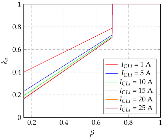
Figure 8.
Dependence of the adaptation factor on the value of the earth fault coefficient for different values .
Table 6.
Short-circuit current values at the FCPI installation site, adaptation criterion settings and information about the start-up of the criterion in the compensated network, = 15 kV, = 120 A, s = 0.1.
To verify the accuracy of the method, computational analyses were performed. The value of the earth fault current that flows at the FCPI location was determined according to relation (7). Furthermore, the settings of the adaptive overcurrent criterion were determined from relation (14) and the classic overcurrent criterion from Equation (9). The analysis was conducted for the network as before, that is, with a capacitive current equal to = 120 A.
Figure 9 shows the maximum determined transition resistances that FCPI can detect operating with the classical zero-sequence current criterion () and the adaptive criterion () for networks with different values of the compensation factor s.
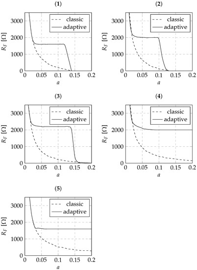
Figure 9.
Comparison of detected transition resistances for overcurrent protections operating with the classical zero-sequence current algorithm and the adaptive algorithm for different values of s: (1) s = −0.2, (2) s = −0.1, (3) s = 0, (4) s = 0.1, (5) s = 0.2.
Using the zero-sequence current adaptive criterion in a compensated network in the form proposed in this subsection, one can obtain, compared to the classical zero-sequence current criterion, a much wider range of transition resistances detected by the FCPI. Regardless of the value of the compensation detuning factor s, for a wide range of the participation factor a, the maximum detected transition resistances are equal to at least = 1500 . This, in turn, allows the zero-sequence current adaptive criterion to qualify as a criterion for detecting high-resistance short circuits in a compensated medium-voltage network. Unfortunately, for uncompensated networks with a large share of the value of the capacitive current of the line behind the FCPI site in relation to the total capacitive current of the network, there is a risk of failure of protection based on the proposed criterion even during the occurrence of a metallic fault.
However, in such a situation, it should be emphasized that:
- (1)
- It is not recommended to operate the network with the compensation detuning factor ;
- (2)
- FCPI’s are installed deep in the network, and then the values of line capacitive current behind the location of a particular device are small; it is estimated that in the vast majority of networks, the situation that for a particular device will not occur.
Therefore, it can be considered that the proposed criterion can significantly improve the efficiency of earth fault detection using a modification of the classical overcurrent criterion, with the modification consisting of including in the setting the RMS value of the zero-sequence voltage measured in the network during an earth fault. For this measurement, for example, simplified methods of local measurement of the zero-sequence voltage can be used, which are described in [30].
4. Simulation Studies of the Adaptive Criterion
4.1. General Remarks
The adaptive zero-sequence current criterion for a compensated network is based on the dependence of the protection current setting on the RMS value of the zero-sequence current measured by a FCPI installed deep in the network. The value of the compensation factor is determined from relation (8), in which it is important to know the earth fault factor , the capacitive current of the line behind the location of the signaling device , and the current error of the zero-sequence current filter . It is assumed that = 0.5 A [34,37,38,45], and this assumption was also made during all previous analyses.
4.2. Simulation Model
A simulation model was built for the study of new algorithms for the detection of earth faults by FCPI in a medium-voltage network in the PSCad 4.2 environment. Hardware platform: Lenovo notebook (Beijing, China), Intel® Core™i5-1035G1, 16 GB RAM, Intel® Iris™Graphics.
The model (Figure 10) represents an HV/MV substation supplied through a transformer with the YNd11 connection group with rated power = 25 MVA. The nominal voltage of the modeled MV network is equal to = 15 kV, which gives a nominal phase-to-ground voltage of = 8660 V. The network can operate with different ways of grounding the neutral point, including the neutral point grounded by a Petersen coil with any value of compensating current, with and without ACFA automation.
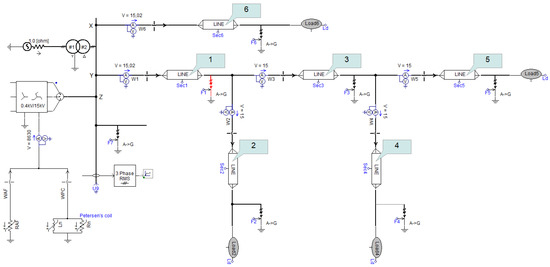
Figure 10.
MV network model used to test new earth fault detection methods by FCPI.
A network with any value of the capacitive earth fault current can be represented in the model, with the entire value of this current divided into two lines:
- Fed from bay Y, which consists of five sections, with the possibility of making a short circuit at the end of each section and measuring electrical quantities at the beginning of each section. The sections are numbered from 1 to 5 (gray rectangles with arrows);
- Fed from bay X, which consists of one section to represent the rest of the network that is not covered by a short circuit. The line fed from bay X is the so-called background of the network.
4.3. Simulations and Results
The procedure for simulation verification of the performance of the adaptation criterion includes the following steps:
- Assumptions: = 120 A, = 150 A, = 20 A;
- n-fold start of simulation for different values of , that is, for different values of capacitive current of the line behind the site of the FCPI;
- Aggregation of the values of the zero-sequence voltage and the zero-sequence current at the location of the FCPI, it is assumed that this can be the beginning of any sections 1–6 (see Figure 10, line sections are numbered in gray rectangles);
- Determination in the spreadsheet of the value of the earth fault coefficient , the adaptation factor and the setting of the criterion ;
- Checking the start-up condition of the protection and evaluating the possibility of tripping it under the given conditions.
The start-up condition of the protection is given by the following relation.
where is determined by Formula (14).
Table 7 compares the fact of start-up occurrence of the adaptive criterion and the classical zero-sequence current criterion under the same conditions. In total, Table 7 shows simulation results for 30 earth faults. The proposed zero-sequence current adaptive criterion was effective for 17 faults, accounting for 57% of all cases. The criterion is effective for all short circuits with a transition resistance less than or equal to = 1750 . The adaptive criterion proved to have an advantage over the classical zero-sequence current criterion, i.e., entering the start-up state when the classical criterion is at rest, in 11 analyzed cases. This translates into the fact that the proposed adaptive zero-sequence current criterion is, in a compensated network with capacitive current = 120 A, earth fault compensation detuning coefficient s = 0.1 and the damping decrement factor = 0.17, at least 37% more effective in detecting high-resistance ground faults than the classical zero-current criterion. Of course, these are rough estimates only for the cases considered, but it can be judged that the adaptive criterion is clearly more effective in detecting high-resistance earth faults.
Table 7.
Comparison of the effectiveness of the zero-sequence adaptive criterion and classical zero-sequence current criterion.
Evaluation of the effectiveness of the adaptive criterion was also performed using the built simulation model for other values of the earth fault compensation detuning coefficient in a network with a total capacitive current equal to = 120 A.
Table 8 shows simplified simulation results, highlighting the start-up of the zero-sequence current adaptive criterion and the classical overcurrent criterion. Short circuits were simulated with transition resistances of = 1000; 1750; 2000 .
Table 8.
Effectiveness of the zero-sequence current adaptive criterion in networks with different values of the earth fault detuning coefficient s.
Of particular importance in the cases analyzed is the situation in which the compensation detuning coefficient s is negative, i.e., the value of the capacitive current exceeds the value of the rated current of the Petersen coil connected at the neutral point of the network. This situation is quite common in practice [46,47] when, due to the expansion of the network, increases and the coil at the neutral point no longer has regulation capabilities. In such a situation, out of 15 simulated short circuits, the classical zero-sequence current criterion had a start-up in 3 cases, while the adaptive criterion had a start-up in 11 cases. This gives a relative increase in the number of detected short circuits of 53%.
In practice, a large overcompensation of the network, i.e., a situation in which the value of the compensation detuning coefficient is greater than , is rarely encountered [46,48]. If significant overcompensation already occurs, the adaptive criterion will also be more effective than the classical overcurrent criterion: In the 15 short circuits considered, an increase in the number of detected short circuits of 20% was observed. This low increase in the effectiveness of the adaptive criterion is related to the narrower range of transition resistances for which the adaptive criterion works. It is active only when .
To verify the effectiveness of the adaptive zero-sequence current criterion presented, Figure 11 shows the maximum values of the detected transition resistance in the modeled network assuming four different earth fault criteria. For a correctly compensated network, the adaptive criterion achieves performance comparable to the admission group criteria. However, it has an advantage over them: If the measurement of is disturbed or unavailable, then the admittance criteria stop working completely. In the case of the adaptive criterion, only the adaptation stops working, and short circuits are then detected with the efficiency that the standard zero-current criterion has.
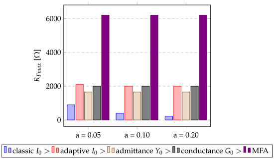
Figure 11.
Maximum values of the detected transition resistance in the modeled network assuming different earth fault criteria.
In addition, the graph shows the claimed effectiveness of the multi-frequency admittance criterion (MFA) developed by ABB [49]. This criterion is very promising, but it requires the use of precise measurements (the required phase angle of the zero-sequence component of the voltage), advanced calculations (analysis of individual harmonics) and thus, a high complexity of the FCPI itself. The method presented in this article has far fewer requirements.
5. Conclusions
The earth fault detection criterion for a compensated network, which uses the value of the zero-sequence voltage to adapt the current setting, is characterized by a much wider range of detected RF transition resistances compared to the classical zero-sequence current criterion. This criterion is particularly effective for networks in which the value of the earth fault compensation detuning factor takes the recommended values in the range of 1.05 to 1.15 . The maximum detected transition resistances are equal to at least = 1500 and are comparable to or higher than the resistances detected by the protections in the admittance group. This, in turn, allows one to qualify the adaptive zero-sequence current criterion to the group of criteria detecting high resistive short circuits in the compensated medium-voltage network. Simulation studies have shown that the use of the adaptive criterion makes it possible to achieve a significant increase in the number of detected earth faults compared to the classic zero-sequence current criterion.
The presented method can be useful, especially in low-cost FCPI, because there is no absolute necessity to precisely determine the vector of the zero-sequence voltage at the measurement site. In addition, it is possible, as also highlighted in the text, to use simplified methods to determine the zero-sequence voltage. Thus, it is possible to saturate the network with a larger number of FCPIs without incurring significant financial resources, which will promote the quality of the fault location, reduce the values of the SAIDI/SAIFI coefficients and improve the overall quality of the electricity supplied to consumers.
Author Contributions
Conceptualization, B.O. and B.Z.; methodology, B.O.; software, B.O.; validation, B.O. and B.Z.; formal analysis, B.O.; investigation, B.O.; resources, B.O. and B.Z.; data curation, B.O.; writing—original draft preparation, B.O.; writing—review and editing, B.Z.; visualization, B.O.; supervision, B.O.; funding acquisition, B.O. All authors have read and agreed to the published version of the manuscript.
Funding
The research was financed from resources of the Polish Ministry of Science and Higher Education for Statutory Activities No. 0711/SBAD/4560.
Data Availability Statement
Not applicable.
Conflicts of Interest
The authors declare no conflict of interest.
Abbreviations
The following abbreviations are used in this manuscript:
| ACFA | active current forcing automation |
| AMI | smart electricity meters |
| FCPI | fault current passage indicator |
| HDI | high density interconnect |
| HV | high voltage |
| IED | intelligent electronic device |
| MFA | Multi Frequency Admittance criterion |
| MV | medium voltage |
| PSCad | Power System Computer Aided Design |
| RMS | root mean square |
References
- Jamali, S.; Bahmanyar, A.; Borhani-Bahabadi, H. A fast and accurate fault location method for distribution networks with dg using genetic algorithms. In Proceedings of the 2015 Smart Grid Conference (SGC), Tehran, Iran, 22–23 December 2015; pp. 110–114. [Google Scholar] [CrossRef]
- Linčiks, J.; Baranovskis, D. Single Phase Earth Fault Location in the Medium Voltage Distribution Networks. Sci. J. Riga Tech. Univ. Power Electr. Eng. 2009, 25, 13–18. [Google Scholar] [CrossRef][Green Version]
- Wang, X.; Zhang, H.; Shi, F.; Wu, Q.; Terzija, V.; Xie, W.; Fang, C. Location of Single Phase to Ground Faults in Distribution Networks Based on Synchronous Transients Energy Analysis. IEEE Trans. Smart Grid 2020, 11, 774–785. [Google Scholar] [CrossRef]
- Jamali, S.; Bahmanyar, A. A new fault location method for distribution networks using sparse measurements. Int. J. Electr. Power Energy Syst. 2016, 81, 459–468. [Google Scholar] [CrossRef]
- Niu, L.; Wu, G.; Xu, Z. Single-Phase Fault Line Selection in Distribution Network Based on Signal Injection Method. IEEE Access 2021, 9, 21567–21578. [Google Scholar] [CrossRef]
- Hänninen, S.; Lehtonen, M. Characteristics of earth faults in electrical distribution networks with high impedance earthing. Electr. Power Syst. Res. 1998, 44, 155–161. [Google Scholar] [CrossRef]
- Djurić, M.B.; Radojević, Z.M.; Terzija, V.V. Digital signal processing algorithm for arcing faults detection and fault distance calculation on transmission lines. Int. J. Electr. Power Energy Syst. 1997, 19, 165–170. [Google Scholar] [CrossRef]
- Iurinic, L.U.; Herrera-Orozco, A.R.; Ferraz, R.G.; Bretas, A.S. Distribution Systems High-Impedance Fault Location: A Parameter Estimation Approach. IEEE Trans. Power Deliv. 2016, 31, 1806–1814. [Google Scholar] [CrossRef]
- Kulkarni, S.; Santoso, S.; Short, T.A. Incipient Fault Location Algorithm for Underground Cables. IEEE Trans. Smart Grid 2014, 5, 1165–1174. [Google Scholar] [CrossRef]
- Radojevic, Z.; Terzija, V.; Djuric, N. Numerical algorithm for overhead lines arcing faults detection and distance and directional protection. IEEE Trans. Power Deliv. 2000, 15, 31–37. [Google Scholar] [CrossRef]
- Mora-Flòrez, J.; Meléndez, J.; Carrillo-Caicedo, G. Comparison of impedance based fault location methods for power distribution systems. Electr. Power Syst. Res. 2008, 78, 657–666. [Google Scholar] [CrossRef]
- Altonen, J.; Wahlroos, A. Novel algorithm for earth-fault location in compensated MV-networks. In Proceedings of the 22nd International Conference and Exhibition on Electricity Distribution (CIRED 2013), Stockholm, Sweden, 10–13 June 2013; pp. 1–4. [Google Scholar] [CrossRef]
- Chunju, F.; Li, K.; Chan, W.; Weiyong, Y.; Zhaoning, Z. Application of wavelet fuzzy neural network in locating single line to ground fault (SLG) in distribution lines. Int. J. Electr. Power Energy Syst. 2007, 29, 497–503. [Google Scholar] [CrossRef]
- Mora-Florez, J.; Barrera-Nunez, V.; Carrillo-Caicedo, G. Fault Location in Power Distribution Systems Using a Learning Algorithm for Multivariable Data Analysis. IEEE Trans. Power Deliv. 2007, 22, 1715–1721. [Google Scholar] [CrossRef]
- Pourahmadi-Nakhli, M.; Safavi, A.A. Path Characteristic Frequency-Based Fault Locating in Radial Distribution Systems Using Wavelets and Neural Networks. IEEE Trans. Power Deliv. 2011, 26, 772–781. [Google Scholar] [CrossRef]
- Rafinia, A.; Moshtagh, J. A new approach to fault location in three-phase underground distribution system using combination of wavelet analysis with ANN and FLS. Int. J. Electr. Power Energy Syst. 2014, 55, 261–274. [Google Scholar] [CrossRef]
- Martins, L.; Martins, J.; Alegria, C.; Pires, V. A network distribution power system fault location based on neural eigenvalue algorithm. In Proceedings of the 2003 IEEE Bologna Power Tech Conference Proceedings, Bologna, Italy, 23–26 June 2003; Volume 2, p. 6. [Google Scholar] [CrossRef]
- IEEE Std C37.114-2014; IEEE Guide for Determining Fault Location on AC Transmission and Distribution Lines. IEEE: Piscataway, NJ, USA, 2015; pp. 1–76. [CrossRef]
- Liang, R.; Fu, G.; Zhu, X.; Xue, X. Fault location based on single terminal travelling wave analysis in radial distribution network. Int. J. Electr. Power Energy Syst. 2015, 66, 160–165. [Google Scholar] [CrossRef]
- Sadeh, J.; Bakhshizadeh, E.; Kazemzadeh, R. A new fault location algorithm for radial distribution systems using modal analysis. Int. J. Electr. Power Energy Syst. 2013, 45, 271–278. [Google Scholar] [CrossRef]
- Thomas, D.W.P.; Carvalho, R.J.O.; Pereira, E.T.; Christopoulos, C. Field trial of fault location on a distribution system using high frequency transients. In Proceedings of the 2005 IEEE Russia Power Tech, Piscataway, NJ, USA, 27–30 June 2005; pp. 1–7. [Google Scholar] [CrossRef]
- Qi, W.; Tang, J.; Yang, C.; Li, Z.; Zhou, L. Research and Development of Novel Transient Waveform Recording Fault Indicators Used in Power Distribution Networks. In Proceedings of the 2022 4th Asia Energy and Electrical Engineering Symposium (AEEES), Chengdu, China, 25–28 March 2022; pp. 863–868. [Google Scholar] [CrossRef]
- Tang, Y.; Chang, Y.; Tang, J.; Xu, B.; Ye, M.; Yang, H. A Novel Faulty Phase Selection Method for Single-Phase-to-Ground Fault in Distribution System Based on Transient Current Similarity Measurement. Energies 2021, 14, 4695. [Google Scholar] [CrossRef]
- Nhede, N. Smart Grid’s Role in Energy Transition and the Top Five Market Leaders. 2021. Available online: https://www.smart-energy.com/industry-sectors/smart-meters/smart-grids-role-in-energy-transition-and-the-top-five-market-leaders/ (accessed on 15 November 2022).
- Jia, K.; Ren, Z.; Bi, T.; Yang, Q. Ground Fault Location Using the Low-Voltage-Side Recorded Data in Distribution Systems. IEEE Trans. Ind. Appl. 2015, 51, 4994–5001. [Google Scholar] [CrossRef]
- Pereira, R.A.F.; da Silva, L.G.W.; Kezunovic, M.; Mantovani, J.R.S. Improved Fault Location on Distribution Feeders Based on Matching During-Fault Voltage Sags. IEEE Trans. Power Deliv. 2009, 24, 852–862. [Google Scholar] [CrossRef]
- Mirshekali, H.; Dashti, R.; Handrup, K.; Shaker, H.R. Real Fault Location in a Distribution Network Using Smart Feeder Meter Data. Energies 2021, 14, 3242. [Google Scholar] [CrossRef]
- Falaghi, H.; Haghifam, M.R.; Tabrizi, M.R.O. Fault indicators effects on distribution reliability indices. In Proceedings of the CIRED 2005—18th International Conference and Exhibition on Electricity Distribution, Turin, Italy, 6–9 June 2005; pp. 1–4. [Google Scholar] [CrossRef]
- Farughian, A.; Kumpulainen, L.; Kauhaniemi, K.; Hovila, P. Intermittent Earth Fault Passage Indication in Compensated Distribution Networks. IEEE Access 2021, 9, 45356–45366. [Google Scholar] [CrossRef]
- Olejnik, B. Alternative method of determining zero-sequence voltage for fault current passage indicators in overhead medium voltage networks. Electr. Power Syst. Res. 2021, 201, 107506. [Google Scholar] [CrossRef]
- Shao, W.; Bai, J.; Cheng, Y.; Zhang, Z.; Li, N. Research on a Faulty Line Selection Method Based on the Zero-Sequence Disturbance Power of Resonant Grounded Distribution Networks. Energies 2019, 12, 846. [Google Scholar] [CrossRef]
- Givelberg, M.; Lysenko, E.; Zelichonok, R. Zero sequence directional earth-fault protection with improved characteristics for compensated distribution networks. Electr. Power Syst. Res. 1999, 52, 217–222. [Google Scholar] [CrossRef]
- Lorenc, J. Admitancyjne Zabezpieczenia Ziemnozwarciowe Kompensowanych Sieci Średnich Napięć; Rozprawy—Politechnika Poznańska, PUT Publishing Office: Poznań, Poland, 1992. [Google Scholar]
- Lorenc, J. Admitancyjne Zabezpieczenia Ziemnozwarciowe; PUT Publishing Office: Poznań, Poland, 2007. [Google Scholar]
- Cerretti, A.; Calone, R.; Fatica, A. Evolution of the Fault Locator on MV distribution networks: From simple stand alone device, to a sophisticated strategic component of the SMART GRID control system. In Proceedings of the 21nd International Conference on Electricity Distribution (CIRED 2011), Frankfurt, Germany, 10–12 October 2011. [Google Scholar]
- Habrych, M.; Wisniewski, G.; Miedziński, B.; Lisowiec, A.; Fjałkowski, Z. HDI PCB Rogowski Coils for Automated Electrical Power System Applications. IEEE Trans. Power Deliv. 2018, 33, 1536–1544. [Google Scholar] [CrossRef]
- Hoppel, W. Sieci Średnich Napięć; Polish Scientific Publishers: Warsaw, Poland, 2017. [Google Scholar]
- Olejnik, B. Effectiveness of Earth Fault Passage Indicators during High-Ohmic Earth Faults in MV Grid. Ph.D. Thesis, Poznan University of Technology, Poznań, Poland, 2020. [Google Scholar]
- Guldbrand, A.; Samuelsson, O. Central or Local Compensation of Earth-Fault Currents in Non-Effectively Earthed Distribution Systems. In Proceedings of the 2007 IEEE Lausanne Power Tech, Lausanne, Switzerland, 1–5 July 2007; pp. 1129–1134. [Google Scholar] [CrossRef]
- Lin, X.; Sun, J.; Kursan, I.; Zhao, F.; Li, Z.; Li, X.; Yang, D. Zero-sequence compensated admittance based faulty feeder selection algorithm used for distribution network with neutral grounding through Peterson-coil. Int. J. Electr. Power Energy Syst. 2014, 63, 747–752. [Google Scholar] [CrossRef]
- Fuchs, E.; Fickert, L. The self-extinguishing current limit and the arc-burning time of compensated 20-kV-power-grids. In Proceedings of the 2012 Electric Power Quality and Supply Reliability, Tartu, Estonia, 11–13 June 2012; pp. 1–6. [Google Scholar] [CrossRef]
- Zydanowicz, J. Elektroenergetyczna Automatyka Zabezpieczeniowa; Scientific and Technical Publishing House: Warsaw, Poland, 1987.
- Poll, J. Löschung von Erdschlusslichtbögen. Elektrizitätswirtschaft 1984, 83, 322–327. [Google Scholar]
- DIN VDE 0845-6-2 VDE 0845-6-2:2014-09; Electromagnetic Influence of Electric Power Supply on Telecommunication Systems. VDE Verlag: Berlin, Germany, 2014.
- Olejnik, B. Adaptive Zero-Sequence Overcurrent Criterion for Earth Fault Detection for Fault Current Passage Indicators in Resistor Grounded Medium Voltage Networks. IEEE Access 2021, 9, 63952–63965. [Google Scholar] [CrossRef]
- Lorenc, J.; Łowczowski, K.; Staszak, B. Earth fault protection supported with adaptive admittance criteria. Przegląd Elektrotechniczny 2018, 8, 132–135. [Google Scholar] [CrossRef]
- Dolinger, S.Y.; Lyutarevich, G.A.; Osipov, S.D. Basic approaches to the implementation of Petersen Coil control system. In Proceedings of the 2015 International Siberian Conference on Control and Communications (SIBCON), Strbske Pleso, Slovakia, 16–18 May 2015; pp. 1–4. [Google Scholar] [CrossRef]
- Meng, J.; Wang, W.; Tang, X.; Xu, X. Zero-sequence voltage trajectory analysis for unbalanced distribution networks on single-line-to-ground fault condition. Electr. Power Syst. Res. 2018, 161, 17–25. [Google Scholar] [CrossRef]
- Altonen, J.; Wahlroos, A. Performance of modern fault passage indicator concept in compensated MV-networks. In Proceedings of the CIRED Workshop 2016, Helsinki, Finland, 14–15 June 2016; pp. 1–4. [Google Scholar] [CrossRef]
Publisher’s Note: MDPI stays neutral with regard to jurisdictional claims in published maps and institutional affiliations. |
© 2022 by the authors. Licensee MDPI, Basel, Switzerland. This article is an open access article distributed under the terms and conditions of the Creative Commons Attribution (CC BY) license (https://creativecommons.org/licenses/by/4.0/).