Article

Control Strategy for Resonant Inverter in High Frequency AC Power Distribution System with Harmonic Suppression and Transient Performance Improvement

1
Shien-Ming Wu School of Intelligent Engineering, South China University of Technology, Guangzhou 511442, China
2
School of Automation Science and Engineering, South China University of Technology, Guangzhou 510641, China
3
New Energy Research Center, South China University of Technology, Guangzhou 510641, China
*
Authors to whom correspondence should be addressed.
Energies 2022, 15(23), 8992; https://doi.org/10.3390/en15238992
Submission received: 4 November 2022 / Revised: 23 November 2022 / Accepted: 24 November 2022 / Published: 28 November 2022

Abstract

:
In high frequency AC (HFAC) distribution system, the resonant inverter is used to improve power quality and keep the stability of the output AC voltage. Aiming at the problems of poor output power quality and slow transient performance caused by unreasonable filter parameter design and load change during inverter operation, a single-phase H-bridge LCLC resonant inverter based on analog circuit controller implement is introduced in this paper for HFAC power distribution system (PDS). In this study, to design harmonic compensator and analyze the responsiveness of the inverter, it is necessary to analyze the output voltage total harmonic distortion (THD) of LCLC resonant inverter and the performance of the open loop system in detail. On the one hand, a proportional-integral-resonant (PIR) controller is designed to maintain the zero static error of the voltage output and suppress the output voltage THD of LCLC resonant inverter. On the other hand, an integral controller combines with phase-shift modulation (PSM) method is presented to effectively improve the transient performance of resonant inverter and provide the fixed frequency of the output voltage. On the basis of the above, the experimental prototype is implemented with the output AC voltage root mean square of 28 V, and the output voltage frequency for resonant inverter is equal to switching frequency. A rated output power of 130 W experimental platform is built to verify the effectiveness of the theoretical analysis, control strategy, and modulation method.

1. Introduction

The high frequency AC (HFAC) power distribution system (PDS) was originally proposed by NASA for 20 kHz space station power distribution [1] in 1988. Meanwhile, it has attracted extensive attention from industry and academia such as lighting [2], telecommunication [3], electric vehicle [4,5], renewable energy micro-grid [6], computer, and commercial [7,8]. Figure 1 shows the structure diagram of HFAC PDS, and HFAC PDS has several advantages such as lower electromagnetic noise, fewer conversion stage, faster dynamic performance, higher power density, and higher efficiency. Consequently, the constant voltage constant frequency (CVCF) inverter is the core equipment of HFAC PDS. In [8], the architecture and topology of HFAC PDS is described in detail, and the performance specific of each application is evaluated. Since the switching frequency is the same as the output frequency of resonant inverter, the resonant inverter can be better applied to DC/HFAC conversion applications. Figure 2 shows the typical topology and modulation of HFAC resonant inverter [9,10,11], which is consists of a DC source (Vdc), a filter capacitor (Cdc), H-bridge switches (Q1Q4), a series-parallel LCLC resonant tank (Ls, Cs, Lp, and Cp), and resistance load (R). Moreover, the series-parallel LCLC resonant tank is widely used in the converter or inverter applications, because of the advantages of better filtering performance, lower output total harmonic distortion (THD), and larger zero-voltage switching (ZVS) parameter freedom.
However, an accurate small signal mathematical model is beneficial to the design of the controller. In [12,13], the state space averaging method has been widely used in conventional pulse width modulation (PWM) converters based on the principle of state variables in continuous time-domain. In HFAC PDS, the series-parallel resonant frequency is close to the output voltage frequency and switching frequency of resonant inverter. When the state space averaging method is adopted, the harmonics of the switching component will be ignored. It is worth noting that the effective component of the state variable will be also neglected and it cannot accurately reflect the dynamic characteristics of resonant converter. In [14], the complete small signal mathematical model of the system is developed by discrete sampling data method. However, when the number of resonant elements increases, the modeling analysis become very complex. Another interesting solution reported in [15] is the discrete time-domain simulation method. It can directly obtain a more accurate mathematical model, but the analytical mathematical equations are difficult to derive.
Furthermore, the control strategy and modulation method based on accurate mathematical model have been the research focus in HFAC PDS. The digital control based on DSP can implement relatively complicated controller, but the sampling delay and tracking error cannot be neglected in the field of HFAC. In [16], an APWM resonant inverter combining half-bridge topology and LCLC-LC resonant tank was proposed to achieve relatively low THD and near-zero switching losses. By PI feedback loop and integral feedforward loop based on analog circuit controller, the dynamic response is improved. However, in order to eliminate the second harmonics, an extra second-order LC filter is required, which increases the volume and cost of resonant inverter. The authors of [17] proposed a two-stage fixed duty ratio resonant inverter without additional second-order LC filter that achieves better power quality, and independent control of the phase angle and magnitude. However, from the experimental results, the output voltage still contains a large number of even-order harmonic components, and the dynamic performance of the inverter has not been verified, which will bring hidden dangers to the safety and stable operation of HFAC PDS. Therefore, it is necessary that both the harmonic suppression capability and transient performance of the inverter are improved.
On the one hand, in order to suppress the output harmonics of resonant inverter in control level, resonant controllers have been widely used in active power filters [18,19,20,21], PWM rectifiers [22], so on. The resonant controller can not only produce infinite gain at the disturbing frequency, but also realize accurate reference signal tracking under different dynamic and disturbance conditions. A harmonic suppression method is proposed by combining resonant control with complex vector control, which restrain the unwanted peaks at the immediate vicinity of specified frequencies [18]. In order to facilitate the analysis and design of PR controllers, Nyquist diagrams and phase-margin criterion are usually adopted, but in [21] it is pointed out that this approach has some limitations when resonant frequencies are higher than the crossover frequency defined by the proportional gain. Additionally, the influence of time delay in [21] is analyzed for the stability of resonant control system, and phase compensation is designed to improve the stability of system. Combined with the conventional PI controller, a proportional-integral-resonant (PIR) in high frequency inverter for harmonic suppression is adopted in this paper.
On the other hand, to compensate the load perturbations, the literature [16] proposed an asymmetrical pulse width modulation (APWM) with voltage feedforward control method, which achieve relatively fast transient performance against the load perturbations. However, the traditional sinusoidal pulse width modulation (SPWM) is applied in low frequency or medium frequency DC/AC inverter [23,24,25], which has several drawbacks such as unattainable soft switching and high electro-magnetic interference (EMI). In [9,11,26], a symmetrical phase-shift modulation (PSM) H-bridge LCLC resonant inverter was proposed to maintain the phase angle unperturbed in magnitude modulation. Hence, in order to simplify the control and modulation, a resonant current feedback integral controller combines with phase-shift modulation (I-PSM) method is proposed to against load variations, which does not require a phase-locked loop (PLL), provide the constant frequency, effectively improves the transient performance of resonant inverter from power converter to follow load transient, and compensate for external load power disturbances.
In a word, the characteristics, output voltage or current harmonics, transient and steady state performance of resonant inverter is considered in the current studies on HFAC PDS [1,2,3,4,5,6,7,8,9,10,11,16,17,26]. However, the high frequency resonant inverter usually adopts a conventional PI controller, and the THD of the output voltage or current is limited by the quality factor of the series-parallel resonant tank. Additionally, for external disturbances, the hybrid control-modulation methods such as single loop control combined with PSM [9,10,17] or voltage feedforward control combined with APWM [16] are often used in high frequency inverters, but the transient performance can still be improved under load disturbance. Therefore, it is necessary to propose corresponding control strategies or modulation methods for harmonic suppression and transient performance improvement in the future research of HFAC PDS. The resonant inverter can be guaranteed to work normally with low THD and fast transient response performance.
In this paper, an overall double closed loop control strategy with PIR controller and I-PSM modulator for high frequency resonant inverter is proposed, which realizes the constant output frequency, without phase-locked loop (PLL), low THD, zero steady state error of the voltage output, and fast transient response. Firstly, the internal relationship between output bridge arm voltage, quality factor and the THD of the inverter output voltage is discussed in detail. It provides a theoretical basis for the design of PIR controller. Thus, the harmonic of the output voltage for high frequency resonant inverter can be effectively suppressed. Secondly, the mathematical model of the open loop system is established, and the open loop state performance of the system is analyzed through bode diagram and pole-zero map. It provides theoretical guidance for the performance analysis of closed-loop system and the design of an integrator in I-PSM modulator. By designing a reasonable proportion coefficient of the integrator, the transient response of the system can be improved. Furthermore, the series-parallel LCLC resonant tank makes the output impedance in inductive state, and the switching devices is in ZVS state, thereby reducing the switching loss of the inverter system. Finally, the effectiveness of the proposed control strategy is verified by the resonant inverter platform.
The remainder of the paper is organized as follows. In Section 2, the output voltage harmonic for resonant inverter is analyzed, and the performance of the open loop system based on fundamental approximation method is described in detail. Section 3 explains the closed loop system with PIR I-PSM, and the excellent performance of the system is revealed by the bode diagram and the corresponding pole-zero map. Section 4 presents the experimental results. Finally, Section 5 concludes the paper.

2. Harmonic Analysis and Open Loop System Description

2.1. Harmonic Analysis for Resonant Inverter

As shown in Figure 2, α is the effective pulse width of PSM, the internal resistance of the energy storage devices (includes inductor and capacitor) and the dead-time of the switching is not considered. It should be noted that α corresponds to the control parameter of resonant inverter. The amplitude of the inverter output voltage can be adjusted by adjusting the width of α. According to the Fourier analysis of non-sinusoidal periodic signals, the output bridge arm voltage Vab can be indicated as
V a b = 4 V d c n π n = 1 , 3 , 5 sin ( n π / 2 ) sin ( D n π / 2 ) sin ( n ω t )
where n denotes the harmonic order, D = α/π, α ∈ (0, π), and ω is the output voltage fundamental angular frequency, ω = 2πf = 2πfs, f is the output voltage frequency of LCLC resonant inverter, fs is the switching frequency of H-bridge.
Thus, for a fully resonant inverter system, each harmonic voltage Vo(n) can be derived as
V o ( n ) = [ 4 V d c sin ( D n π / 2 ) ] / ( n π ) Q s Q p ( 1 n 2 ) ( 1 n 2 ) + 1 + j Q s ( n n 1 )
where Qs and Qp is the quality factor of the LsCs series resonant tank and LpCp series resonant tank, respectively. Qs = 1/(ωCsR) = (ωLs)/R, Qp = ωCpR = R/(ωLp).
According to Equation (2), the THD of the inverter output voltage THDvo can be deduced as
T H D v o = n = 3 , 5 | V o ( n ) | 2 V o ( n = 1 ) = n = 3 [ sin ( D n π / 2 ) ] 2 [ Q s Q p ( n n 1 ) ( 1 n 2 ) + n ] 2 + [ Q s ( n 2 1 ) ] 2 | sin ( D π / 2 ) |
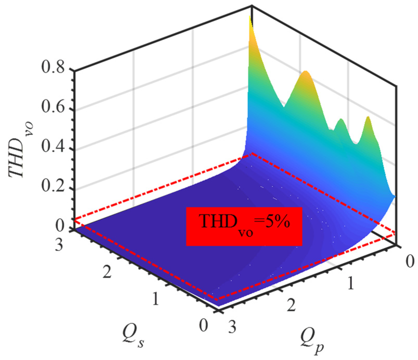
Therefore, as shown in Figure 3, the relationship among THDvo, Qs and Qp can be obtained based on Equation (3). It can be found that Qs and Qp will affect the size of THDvo. In addition, the IEEE Std. 1547.2-2008 and IEEE Std. 519-1992 have proposed harmonic limitation requirements, requiring that the THD of the inverter output voltage or current is less than 5% [27,28]. Based on theoretical analysis, the size of THDvo can be determined by LCLC resonant tank. However, in practical engineering applications, line impedance, parasitic parameters and parameter uncertainty will cause the quality factor Qs and Qp to change, thus affecting the size of THDvo. In the next section, from the perspective of control, a PIR controller is adopted to overcome the influence of other factors on THDvo, which realize the harmonic suppression of the inverter output voltage.

2.2. Performance Description of the Open Loop System

Figure 4 shows the equivalent circuit and system block diagram of LCLC resonant inverter. In order to obtain a high quality factor resonant inverter, according to the simplified equivalent circuit model, a simple linear modeling based on fundamental approximation method is derived in [10]. The transfer function from inverter output voltage to control phase-shift pulse width G(s), inverter output voltage to input DC voltage Gvv(s), and inverter output voltage to inverter output current Gvi(s) can be expressed as shown in Equation (4), respectively.
{ G v α ( s ) = V o ( s ) α ( s ) = 2 V d c cos ( π α / 2 ) C s L p s 2 L s C s L p C p s 4 + ( L s C s + C s L p + L p C p ) s 2 + 1 G v v ( s ) = V o ( s ) V d c ( s ) = 4 sin ( π α / 2 ) C s L p s 2 / π L s C s L p C p s 4 + ( L s C s + C s L p + L p C p ) s 2 + 1 G v i ( s ) = V o ( s ) I o ( s ) = L s C s L p s 3 L p s L s C s L p C p s 4 + ( L s C s + C s L p + L p C p ) s 2 + 1
Based on Equation (4), the corresponding eigenvalue equation D1(s) from the transfer function Gvv(s) can be written as
D 1 ( s ) = a 1 s 4 + b 1 s 3 + c 1 s 2 + d 1 s + 1
where
a 1 = L s C s L p C p b 1 = L s C s L p R c 1 = L s C s + C s L p + L p C p d 1 = L p R
The coefficients from Equation (5) determine the roots and the open loop stability of the system. In order to facilitate the transient performance analysis of the open loop system, Figure 5 shows the pole-zero map of Gvv(s). It can be found that the poles are on the imaginary axis. Notice that, the real part of the pole corresponds to the power of the natural exponent e, and the imaginary part corresponds to the sine. When it is close to the imaginary axis, the exponential decay is slower, which may approximate the constant amplitude oscillation. The convergence rate of the system becomes slow and it is difficult to stabilize, which means that the transient performance of the open loop system is poor.
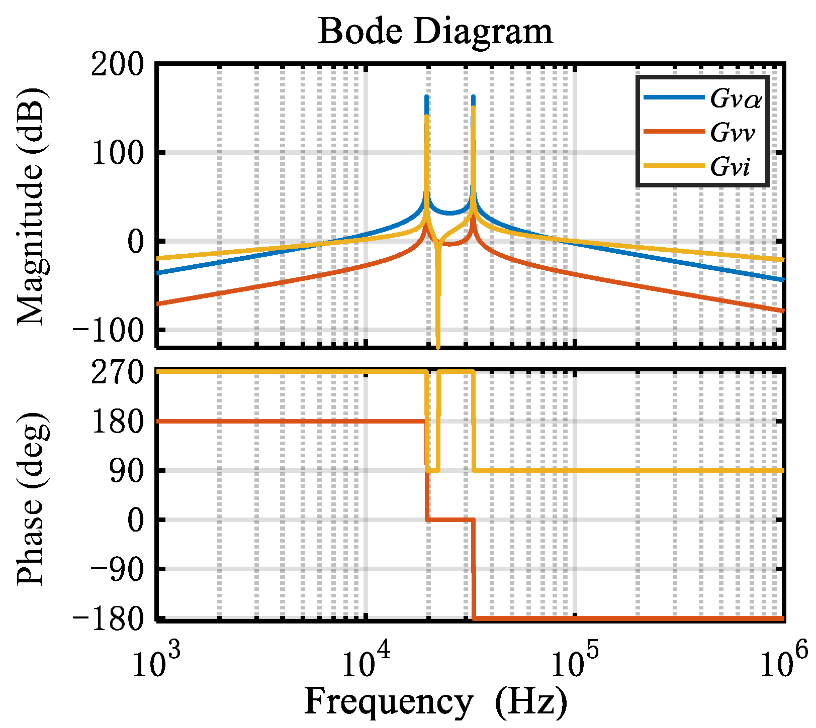
Hence, in order to intuitively analyze the open loop system, according to Equation (4), Figure 6 shows the corresponding open loop system bode diagram of G(s), Gvv(s) and Gvi(s). Where the two spikes are series and parallel resonance points.

3. Closed Loop Control and Performance Analysis of the System

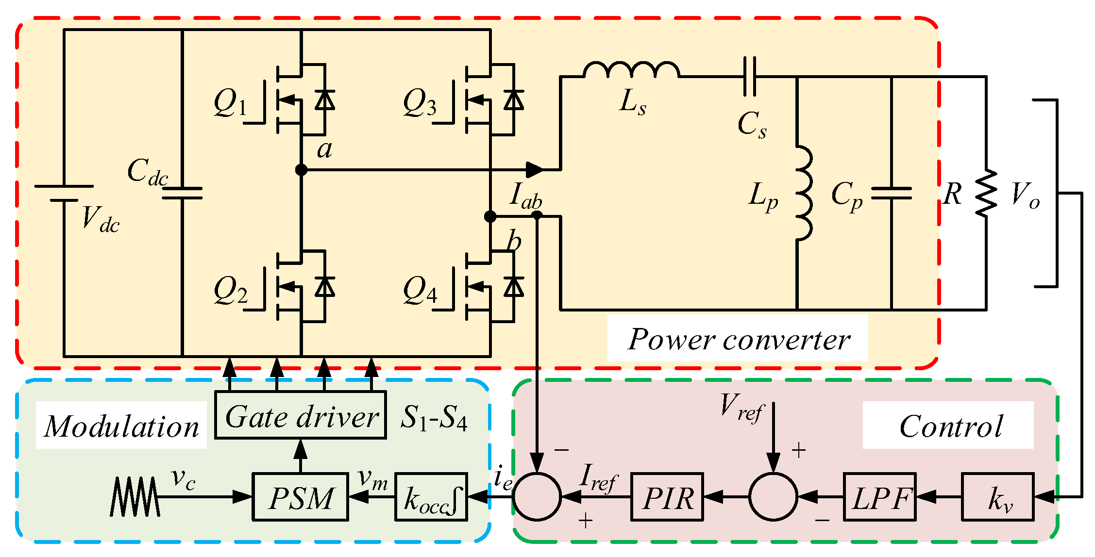
The control schematic of whole LCLC resonant inverter system is shown in Figure 7, which contains power converter part, control and modulation part. Where the control and modulation part are composed of second-order low-pass filter (LPF), voltage feedback controller (PIR controller), I-PSM, and switching driver circuit. The power converter part realizes DC to AC transformation. The control and modulation part achieve harmonic suppression of output voltage and improve transient response performance of resonant inverter, respectively.

3.1. Control Strategy and Analysis Based on PIR

In order to realize the PIR I-PSM method, the low frequency signal is then reserved by using the second-order LPF shown in Equation (6).
G L P F ( s ) = k l p f ω n 2 s 2 + ω n s / Q + ω n 2
where klpf is the LPF coefficient, ωn is the characteristic angular frequency, Q is the quality factor, Q = ωn/2ωc-lpf, and ωc-lpf is the crossover angular frequency of the second-order LPF, ωc-lpf = 2πfc-lpf, fc-lpf is the corresponding crossover frequency.
The second-order LPF can be readily realized by using a universal active filter analog integrated chip (IC) UAF42 of Texas Instruments (TI), which includes on-chip 1 nF ± 0.5% capacitors for performing different filtering functions. Figure 8 shows the overall layout of the chip TI-UAF42, where V1, V2, and V3 are different inputs and can correspond to different filtering outputs. The similar structure can be used for realizing LPF, band-pass filter (BPF) and high-pass filter (HPF). To block interference induced by high-order harmonics and achieve satisfactory dynamic response, Q is set to 25, implying fc-lpf = 500 Hz. In addition, the external tuning resistance RQ is set to 10 kΩ. In order to meet the resonant frequency at 25 kHz, the external frequency setting resistors are set to RH = RB = 6.366 kΩ, which can be composed of a 6 kΩ fixed resistor in series with a 1 kΩ adjustable resistor to maintain adequate accuracy.
In order to adjust the output voltage of resonant inverter, PI controller is usually used to track the reference signal, where the input signal of the controller is the difference between the reference voltage and the output voltage feedback signal. Due to PI controller is a first-order controller, it can accurately and quickly track the reference signal command for the DC component in the control system, while it has almost no suppression for others high-order harmonic components. Moreover, for passive filter devices, the fixed quality factor in the resonant tank has limited ability to suppress harmonics. In order to overcome the abovementioned shortcomings, a PIR controller is presented, and the transfer function of PIR controller is expressed as
G P I R ( s ) = k p + k i s + 2 k r ω c s s 2 + 2 ω c s + ω 2
where kp, ki, and kr is the proportional coefficient, integral coefficient and resonant coefficient of PIR controller, respectively. ωc is the bandwidth of the resonant controller concerning −3 dB cutoff frequency, which is used to reduce the sensitivity of the regulator to fundamental frequency changes.
The introduction of resonance controller in PIR controller does not change the amplitude-frequency and phase-frequency characteristic trend of the PI controller, but only produced a spike near the resonance frequency. When the reference voltage signal passes through the PIR controller, the DC component can still be tracked with zero-steady state error by the PI controller, and the fundamental wave component can be tracked with zero-steady state error by the resonant controller at the resonance frequency. The bode diagram of PIR controller with different parameters is shown in Figure 9. When ki and kr are constant, kp increases, the resonant frequency range decreases, but if the value of kp is too small, the phase will be severely lagging. When the value of ki changes, the low frequency gain increases with the increase in ki, but larger ki will cause the phase lag. Therefore, ki should be determined according to the regulation of fundamental DC component in the control system. When the resonance coefficient kr changes, the gain of the resonance point increases with the increase in kr, which will also cause the resonance frequency range to increase. However, if the value of kr is too large, the phase will lead. In addition, smaller kr will reduce the gain of the resonance point and the range of resonance. The controller bandwidth can be extended by increasing ωc, as shown in Figure 9d. Ideally, the greater kr and ωc will obtain the better performance in control system [29]. However, an overlarge kr can lead to control system instability, while a larger or smaller ωc will affect the frequency-selecting property. Therefore, kr and ωc should be seriously considered.

3.2. I-PSM Method

The integral controller combines with phase-shift modulation method is presented as shown in Figure 10, where ie is the error of PIR controller output signal Iref and the resonant current Iab feedback signal, vc represents triangular carrier signal, vm represents modulation signal, and S1-S4 represents the driver signal of power switching devices Q1Q4.
The input signal of the integral controller is the error signal ie. The modulation signal vm is the output of the integral controller and is given in Equation (8), where km is the sampling gain of the integrator. In order to prevent integral saturation, km should select the appropriate value. For the I-PSM method, the value of km is selected between 0.01~0.04 of the switching frequency fs.
v m ( t ) = k m i e ( t ) d t = k m [ I r e f ( t ) I a b ( t ) ] d t
The PWM signal of power switching devices are generated by comparing vc and vm. The driving signals of S1 and S2 (S3 and S4) are complementary. In addition, the driving signal S3 lag the driving S1. In others words, a phase difference exists between the power switching driving signals S1 and S3. When G1 and G4 are turned on, Vab = Vdc, and when G2 and G3 are turned on, Vab = –Vdc. The power is transferred from the DC power supply to the resistive load through LCLC fourth-order resonant tank. However, when G1 and G3 are turned on or turned off, Vab = 0. The LCLC resonant tank provides energy to the resistive load. Therefore, the output voltage of high-frequency LCLC resonant inverter is regulated by changing the size of the phase-shift angle or phase difference between the power switching driving signals S1 and S3.

3.3. Performance Analysis of Closed Loop System

In order to verify the feasibility of PIR controller, Figure 11 shows the control block diagram of plant in detail and the system stability comparison, where kv is the sampling amplification or reduction coefficient, km represents integral coefficient and kg is the gain of H-bridge. Thus, the expansion expression Tv(s) of the final open loop transfer function with the proposed controller can be written as Equation (9), where GPIR(s) is the transfer function of PIR controller, Gi(s) is the transfer function of the equivalent I-PSM, Gs(s) is the transfer function of LsCs series resonant tank, and Gp(s) is the LpCp series resonant tank transfer function with load.
T v ( s ) = G P I R ( s ) G i ( s ) G s ( s ) G p ( s ) 1 + G i ( s ) G s ( s ) + G i ( s ) G p ( s )
Thus, the corresponding eigenvalue equation D2(s) from Equation (9) can be written as
D 2 ( s ) = a 2 s 7 + b 2 s 6 + c 2 s 5 + d 2 s 4 + e 2 s 3 + f 2 s 2 + g 2 s + h 2
where
a 2 = a 1 R b 2 = 2 a 1 ω c R + b 1 / R c 2 = a 1 ω 2 R + b 1 ( 2 ω c / R + k m k g ) + ( L s C s + L p C p + k m k g C s L p C p ) R d 2 = b 1 ( ω 2 / R + 2 ω c k m k g ) + 2 ω c ( L s C s + L p C p + k m k g C s L p C p ) R + k m k g C s L p + L p e 2 = ω 2 ( b 1 k m k g + k m k g C s L p C p R + L s C s R + L p C p R ) + 2 ω c ( k m k g C s L p + L p ) + ( k m k g C s + k m k g L p + k m k g C s L p + 1 ) R f 2 = ω 2 ( k m k g C s L p + L p ) + 2 ω c ( k m k g C s + k m k g L p + 1 ) R + ( 2 k p ω c + k i + 2 k r ω c ) k m k g C s L p R g 2 = ω 2 ( k m k g C s + k m k g L p + k p k m k g C s L p + 1 ) R + 2 k i ω c k m k g C s L p R h 2 = k i ω 2 k m k g C s L p R
It should be noted that the coefficients from Equation (10) determine the roots, transient response performance and therefore the closed loop stability of the system. From the aforementioned analysis, based on Equations (4) and (9), Figure 12 shows the bode diagram comparison of LCLC resonant inverter, where kp = 24, ki = 45, kr = 60, and ωc = 15 rad/s. It can be seen that the phase margin (PM) is –125° and 56.7°, respectively. Additionally, the gain margin (GM) is 4.11 dB at cross-over frequency. Therefore, the LCLC resonant inverter system is stable under closed loop control and full load. At this time, it can be found that the load is equivalent to adding passive damping (PD) to the high frequency inverter to attenuate the resonance spike of the fourth-order filter.
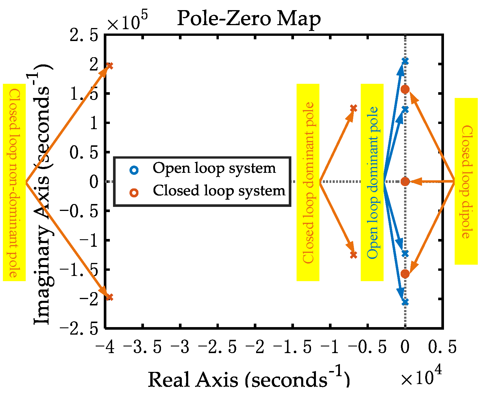
According to Figure 12, Figure 13 shows the corresponding pole-zero comparison diagram of LCLC resonant inverter. It can be clearly seen that the dominant pole of the open loop system is distributed on the imaginary axis, the convergence speed of the system is relatively slow, and the system may be in an unstable state. However, for the closed loop control system with the proposed control strategy, the closed loop dominant pole is far away from the imaginary axis and located in the negative half region of the real axis, which improves the transient performance of the system. Simultaneously, the closed loop non-dominant pole is away from the closed loop dominant pole and the imaginary axis, and the impact on the closed loop system performance is negligible.

4. Experimental Results

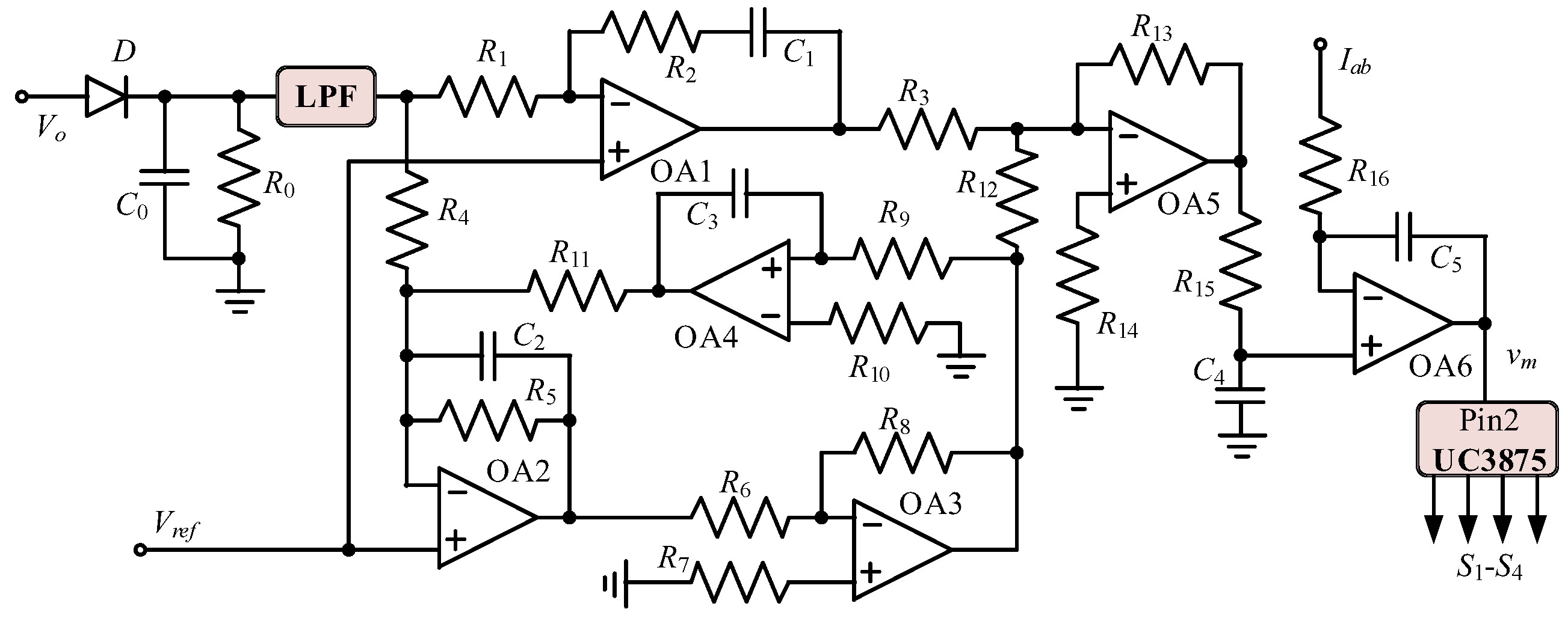
In order to verify the validity and feasibility of the proposed analog circuit control strategy and modulation method, the experimental verification is carried out based on a 28 V/130 W HFAC LCLC resonant inverter. The hardware implementation of the closed loop feedback control analog circuit is illustrated in Figure 14 that is constructed by LPF (TI-UAF42), operational amplifiers (OA1–OA6), and phase-shifted resonant controller IC UC3875. Where kp = R2/R1, ki = 1/(R1C1), kr = 1/(R4C2), ωc = 1/(R5C2), ω2 = 1/(R9R11C2C3), and km = 1/(R16C5). The parameters of the whole resonant inverter system are summarized in Table 1.
Figure 15 shows the experimental waveforms of the output voltage Vo, resonant current Iab and output bridge arm voltage Vab. It can be found from Figure 15 that the phase of Iab is lagged behind the phase of Vab, which satisfies the soft switching condition and the impedance of LCLC series-parallel resonant tank should exhibit inductive reactance state [11,16,26,30]. It means that the ZVS feature of H-bridge switches is achieved. On the one hand, it can greatly reduce the power switching losses and conduction losses of the power switching. On the other hand, the power switching noise is reduced and the voltage stress of the power switching is also reduced. Additionally, it can be seen from the blue waveform in Figure 15 that the output voltage of resonant inverter has good steady state performance and the peak of the output voltage is about 39.6 V.
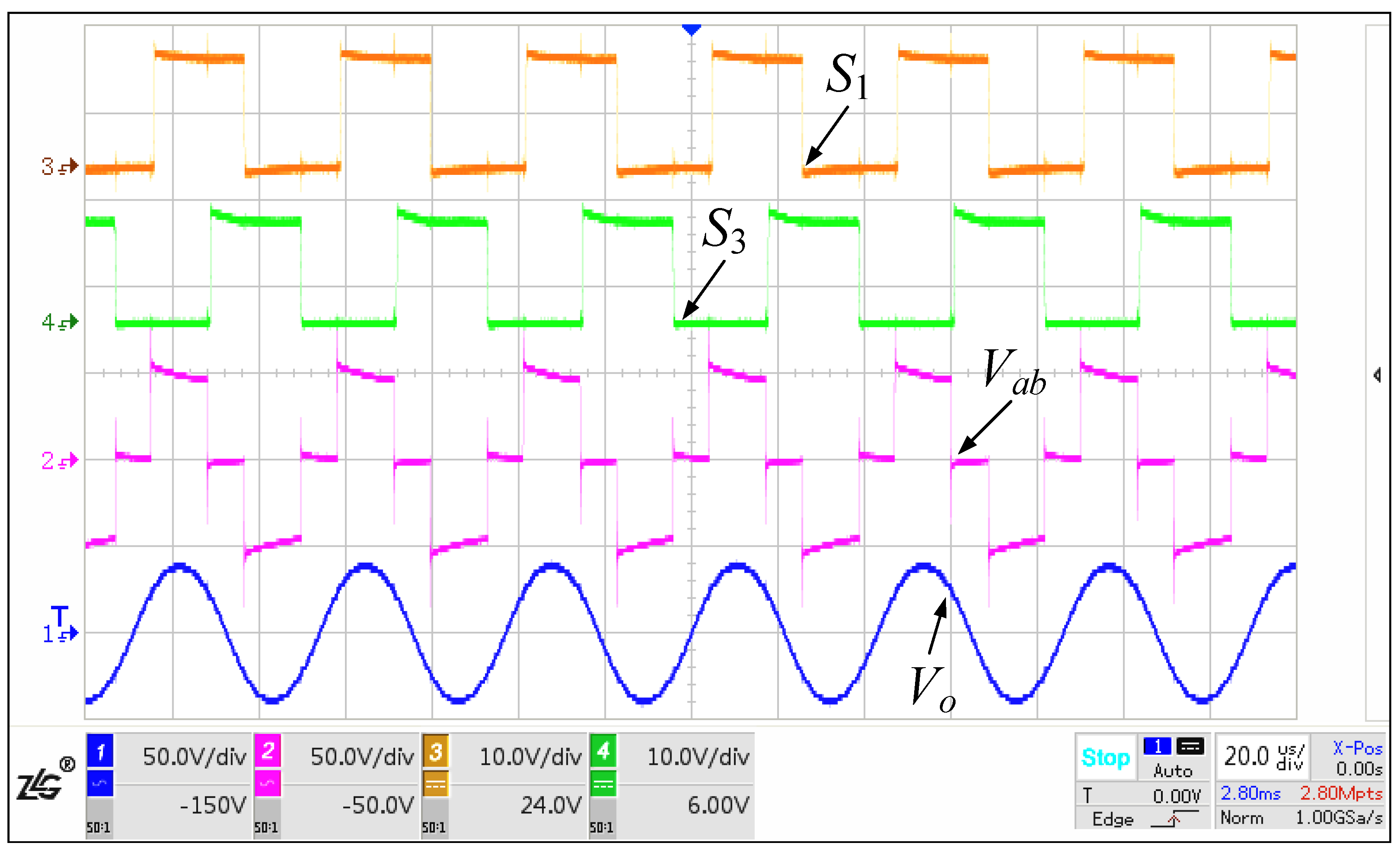
Figure 16 shows the experimental waveforms of the output voltage Vo, output bridge arm voltage Vab, power switching driving signals S1 and S3. Simultaneously, it can be seen that a phase shift angle exists between the power switching driving signals S1 and S3. The power switching gate signals S1S4 generated by UC3875 is magnified by TLP250 to drive IRF530N. The switching frequency and output voltage frequency of LCLC resonant inverter are the same and maintain about 25 kHz. In addition, the DC power supply produces a constant 50 V output voltage. Meanwhile, the output H-bridge voltage Vab has three levels, which the three levels are –50 V, 0 and 50 V.
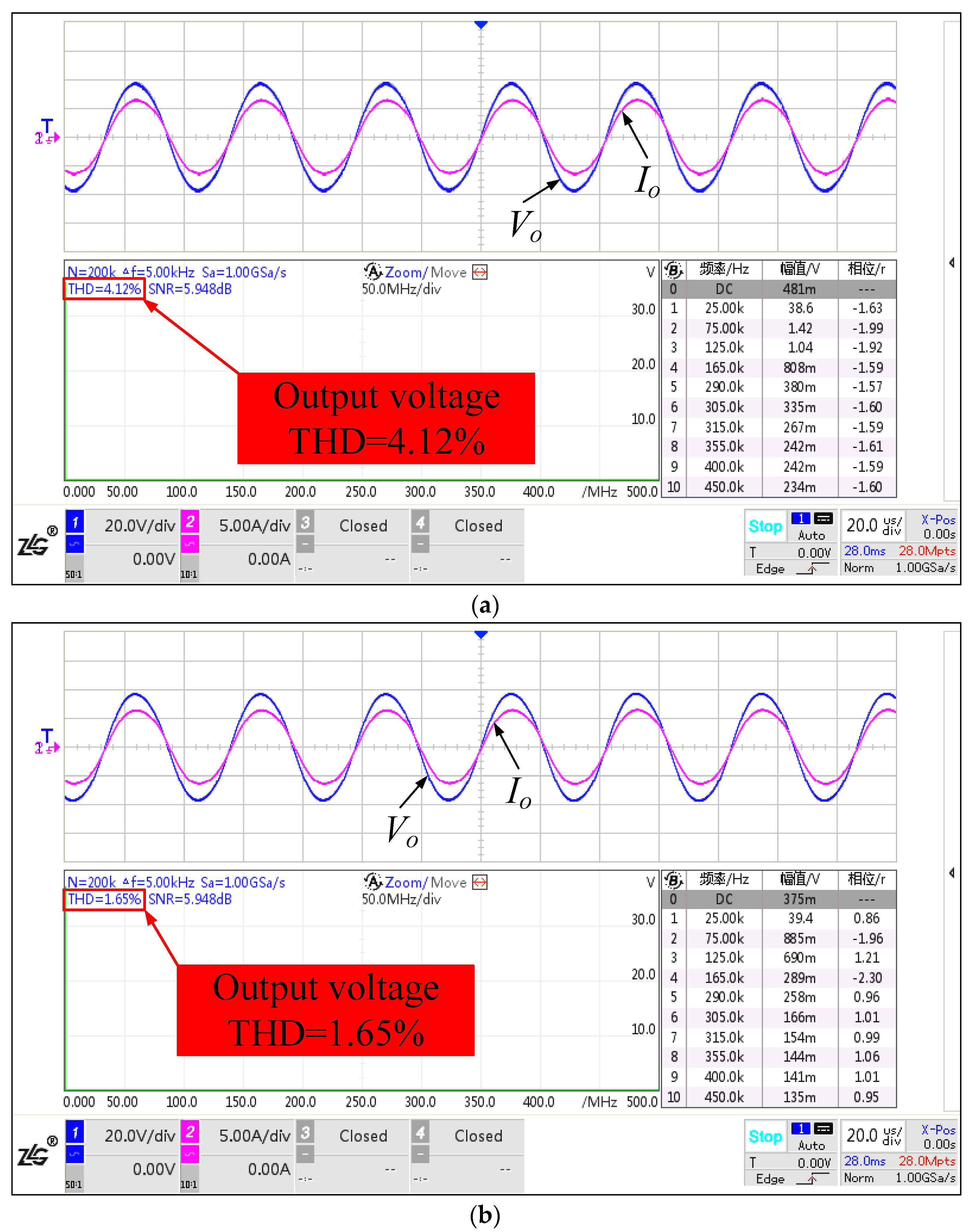
The output voltage and current of inverter with PI controller and PIR controller under full load are shown in Figure 17. It can be clearly seen that the low THD of the output voltage for resonant inverter could be achieved with PIR controller and the output voltage is close to a sinusoidal waveform. Moreover, the measured THD of the output voltage is 1.65%, the DC component is only 375 mV, the output voltage peak is 39.4 V, and the steady state error of fundamental wave is low, as shown in Figure 17b. It means that HFAC LCLC resonant inverter has better static performance and harmonic attenuation capability by adopting PIR controller.
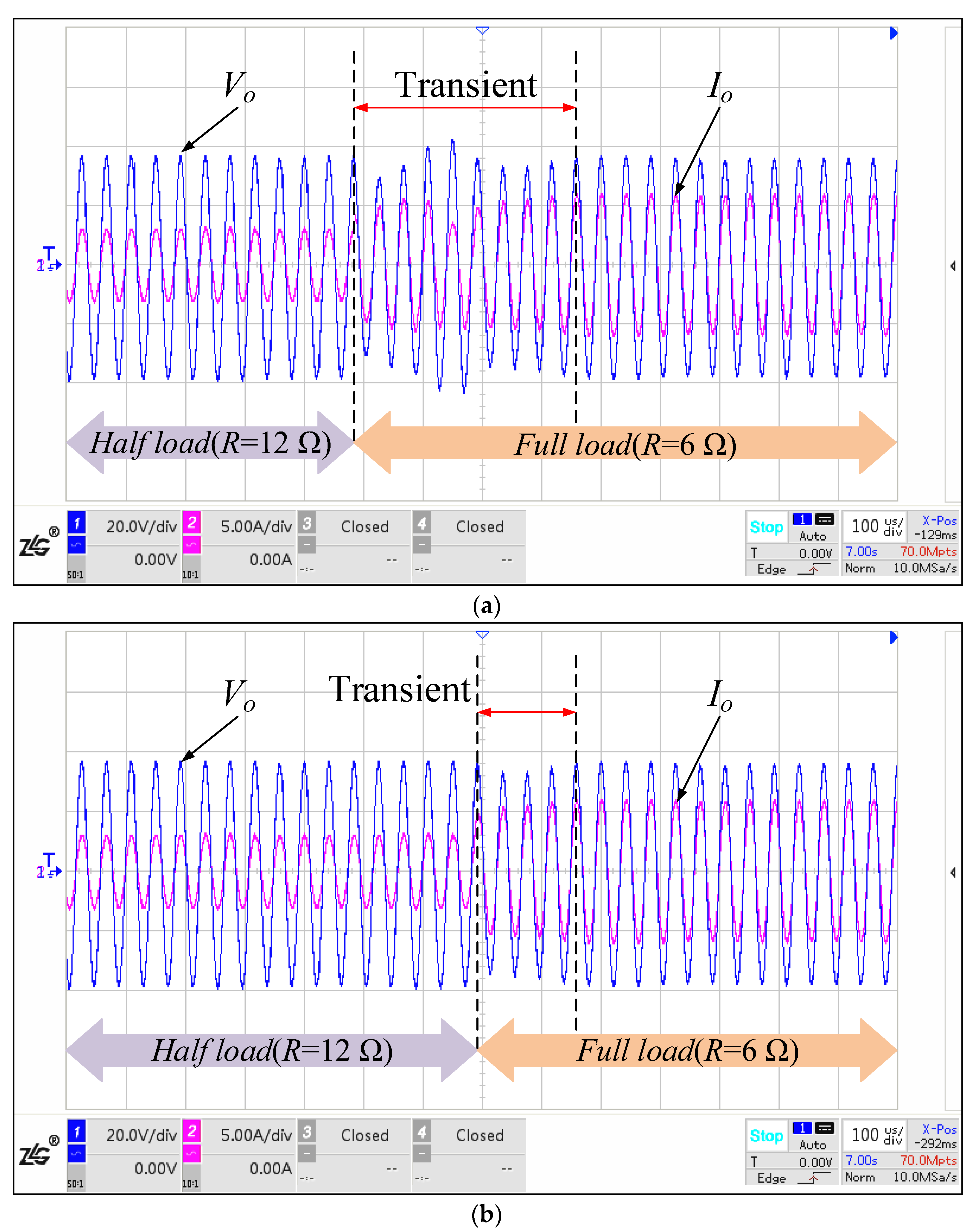
Figure 18 shows the transient performance comparison of load variation with PSM and with I-PSM. When the modulation method adopted PSM, it takes about eight operating cycles for the output voltage and current of the LCLC series-parallel resonant inverter to remain the original state from full load to half load. However, it can be observed from Figure 18b that the output voltage and current of the LCLC resonant inverter can be restored to the original state in only four operating cycles by adopting I-PSM method when the resistive load is adjusted from a half load to full load. In others words, the transient performance of the LCLC resonant inverter can be improved by I-PSM method.
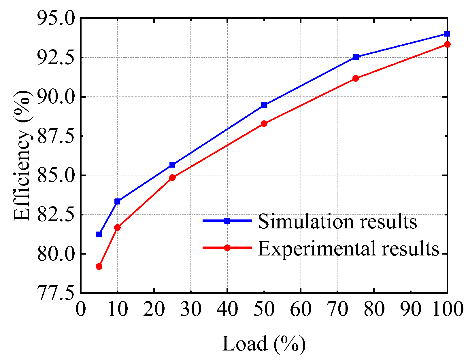
Figure 19 shows the conversion comparison efficiency between the simulation results and experimental result under load variations. The curvature varied with the output current of the LCLC resonant inverter is almost similar. Due to the power switching devices works in soft switching state, the switching loss of HFAC LCLC resonant inverter is reduced. It can be seen from Figure 19 that the maximum conversion efficiency of experimental result is achieved 93.33% at full load, while the minimum conversion efficiency is close to 80% at 5% load.

5. Conclusions

In this paper, a double closed loop control strategy with PIR controller and I-PSM modulator for single-phase H-bridge LCLC resonant inverter is proposed in HFAC PDS. When the quality factor of the LCLC resonant tank changes due to parameter uncertainty, the THD of the output voltage or current will be affected. Therefore, a PIR controller is designed to solve the problem of output voltage or current harmonics, so that the resonant inverter has zero steady state error output and superior harmonic suppression ability. In addition, aiming at the slow transient response of the system under load disturbance, a modulation method combining integrator with PSM is proposed to improve the transient performance. For the proposed control strategy, it can be easily implemented with analog control IC and it has faster operating rate than the conventional digital control. The experimental prototype and results show that a low THD and fast transient performance can be adopted by using PIR I-PSM control strategy for the high frequency inverter with voltage/power of 28 V/130 W. A peak efficiency of 93.33% under full load condition can be obtained by realizing the soft switching state and lower than 1.65% THD output AC voltage can be achieved. Furthermore, the proposed harmonic suppression controller and transient performance improvement modulator can also be used in other high frequency resonant inverter applications, such as induction heating, ozone generator, high-intensity-discharge lamp ballast, and intelligent vehicle.

Author Contributions

Conceptualization, H.Z. and J.L.; methodology, H.Z.; software, H.Z., Z.F. and M.M.; validation, H.Z., Z.F. and M.M.; formal analysis, H.Z., P.Z. and B.Z.; investigation, P.Z. and B.Z.; resources, J.L. and J.Z.; data curation, H.Z. and J.L.; writing—original draft preparation, H.Z.; writing—review and editing, H.Z.; visualization, H.Z.; supervision, J.L. and J.Z.; project administration, J.L.; funding acquisition, J.L. and J.Z. All authors have read and agreed to the published version of the manuscript.

Funding

This work was supported in part by National Natural Science Foundation of China under grant 61573115 and 51877085, in part by Guangdong Natural Science Foundation under grant 2022A1515010150 and 2021A1515011347), and in part by Joint Laboratory of Energy Saving and Intelligent Maintenance for Modern Transportations.

Institutional Review Board Statement

Not applicable.

Informed Consent Statement

Not applicable.

Data Availability Statement

Not applicable.

Acknowledgments

The authors would like to express their sincere gratitude to all our respective reviewers and editors for their pertinent and constructive comments.

Conflicts of Interest

The authors declare no conflict of interest.

References

  1. Hansen, I.-G. Status of 20kHz Space Station Power Distribution Technology; TM 100781; NASA: Washington, DC, USA, 1988. [Google Scholar]
  2. Ng, S.-Y.; Luk, P.-C.; Ken, J. High frequency AC distributed power system for fluorescent lighting. In Proceedings of the 2011 14th European Conference on Power Electronics and Applications, Birmingham, UK, 30 August–1 September 2011; Volume 1, pp. 1–10. [Google Scholar]
  3. Jain, P.; Pinheiro, H. Hybrid high frequency AC power distribution architecture for telecommunication systems. IEEE Trans. Aerosp. Electron. Syst. 1999, 35, 138–147. [Google Scholar] [CrossRef]
  4. Bose, B.; Kin, M.-H.; Kankam, M.-D. High frequency AC vs. DC distribution system for next generation hybrid electric vehicle. In Proceedings of the 1996 IEEE IECON 22nd International Conference on Industrial Electronics, Control, and Instrumentation, Taipei, Taiwan, 9 August 1996; Volume 2, pp. 706–712. [Google Scholar]
  5. Ma, X. High frequency AC pulse density modulation theory and its application in hybrid electric vehicle drive system. In Proceedings of the 4th International Power Electronics and Motion Control Conference, Xi’an, China, 14–16 August 2004; Volume 2, pp. 827–830. [Google Scholar]
  6. Chakraborty, S.; Simoes, M.-G. Experimental evaluation of active filtering in a single-phase high-frequency AC microgrid. IEEE Trans. Energy Convers. 2009, 24, 673–682. [Google Scholar] [CrossRef]
  7. Moo, C.-S.; Chen, W.-M.; Hsieh, H.-K. Electronic ballast with piezoelectric transformer for cold cathode fluorescent lamps. IEE Proc.-Electr. Power Appl. 2003, 50, 278–282. [Google Scholar] [CrossRef]
  8. Jain, P.; Pahlevaninezhad, M.; Pan, S.; Drobnik, J. A Review of high-frequency power distribution systems: For space, telecommunication, and computer applications. IEEE Trans. Power Electron. 2014, 29, 3852–3863. [Google Scholar] [CrossRef]
  9. Ye, Z.; Jain, P.-K.; Sen, P.-C. A full-bridge resonant inverter with modified phase-shift modulation for high-frequency AC power distribution systems. IEEE Trans. Ind. Electron. 2007, 54, 2831–2845. [Google Scholar]
  10. Liu, J.; Cheng, K.-W.-E. μ-based robust controller design of LCLC resonant inverter for high-frequency power distribution system. IET Power Electron. 2013, 6, 652–662. [Google Scholar] [CrossRef]
  11. Liu, J.; Zeng, J. An integrated controller for high-frequency LCLC resonant inverter with phase-shifted control and frequency regulation. Int. J. Circ. Theor. Appl. 2017, 45, 47–62. [Google Scholar] [CrossRef]
  12. Nabinejad, A.; Rajaei, A.; Mardaneh, M. A systematic approach to extract state-space averaged equations and small-signal model of partial-power converters. IEEE J. Emerg. Select. Top. Power Electron. 2020, 8, 2475–2483. [Google Scholar] [CrossRef]
  13. Azer, P.; Emadi, A. Generalized state space average model for multi-phase interleaved buck, boost and buck-boost DC-DC converters: Transient, steady-state and switching dynamics. IEEE Access 2020, 8, 77735–77745. [Google Scholar] [CrossRef]
  14. Sanders, S.-R.; Noworolski, J.-M. Generalized averaging method for power conversion circuits. IEEE Trans. Power Electron. 1991, 6, 251–259. [Google Scholar] [CrossRef] [Green Version]
  15. Mohammadi, M.; Degioanni, F.; Mahdavi, M.; Ordonez, M. Small-signal modeling of LLC converters using homopolarity cycle. IEEE Trans. Power Electron. 2020, 35, 4076–4093. [Google Scholar] [CrossRef]
  16. Qiu, M.; Jain, P.-K.; Zhang, H. An APWM resonant inverter topology for high frequency AC power distribution systems. IEEE Trans. Power Electron. 2004, 19, 121–129. [Google Scholar] [CrossRef]
  17. Ye, Z.; Jain, P.-K.; Sen, P.-C. A two-stage resonant inverter with control of the phase angle and magnitude of the output voltage. IEEE Trans. Power Electron. 2007, 54, 2797–2812. [Google Scholar]
  18. Herman, L.; Papic, I.; Blazic, B. A proportional-resonant current controller for selective harmonic compensation in a hybrid active power filter. IEEE Trans. Power Deliv. 2014, 29, 2055–2065. [Google Scholar] [CrossRef]
  19. Lee, T.; Hu, S. An active filter with resonant current control to suppress harmonic resonance in a distribution power system. IEEE J. Emerg. Select. Top. Power Electron. 2016, 4, 198–209. [Google Scholar] [CrossRef]
  20. Zhou, S.; Zhang, Y.; Liu, Z.; Liu, J.; Zhou, L. Implementation of cross-coupling terms in proportional-resonant current control schemes for improving current tracking performance. IEEE Trans. Power Electron. 2021, 36, 13248–13260. [Google Scholar] [CrossRef]
  21. Yepes, A.-G.; Freijedo, F.-D.; Lopez, Ó.; Doval-Gandoy, J. Analysis and design of resonant current controllers for voltage-source converters by means of Nyquist diagrams and sensitivity function. IEEE Trans. Ind. Electron. 2011, 58, 5231–5250. [Google Scholar] [CrossRef]
  22. Trinh, Q.-N.; Wang, P.; Choo, F.-H. An improved control strategy of three-phase PWM rectifiers under input voltage distortions and DC-offset measurement errors. IEEE J. Emerg. Select. Top. Power Electron. 2017, 5, 1164–1176. [Google Scholar] [CrossRef]
  23. Lakka, M.; Koutroulis, E.; Dollas, A. Development of an FPGA-based SPWM generator for high switching frequency DC/AC inverters. IEEE Trans. Power Electron. 2014, 29, 356–365. [Google Scholar] [CrossRef]
  24. Jammala, V.; Yellasiri, S.; Panda, A.-K. Development of a new hybrid multilevel inverter using modified carrier SPWM switching strategy. IEEE Trans. Power Electron. 2018, 33, 8192–8197. [Google Scholar] [CrossRef]
  25. Sarker, R.; Datta, A.; Debnath, S. FPGA-based high-definition SPWM generation with harmonic mitigation property for voltage source inverter applications. IEEE Trans. Ind. Inf. 2021, 17, 1352–1362. [Google Scholar] [CrossRef]
  26. Liu, J.; Cheng, K.-W.-E.; Ye, Y. A cascaded multilevel inverter based on switched-capacitor for high-frequency AC power distribution system. IEEE Trans. Power Electron. 2014, 29, 4219–4230. [Google Scholar] [CrossRef]
  27. IEEE Std 1547.2-2008; IEEE Standard for Interconnecting Distributed Resources with Electric Power Systems. IEEE Application Guide for IEEE Std 1547(TM); IEEE: Piscataway, NJ, USA, 2009; pp. 1–217.
  28. IEEE Std 519-2014; IEEE Recommended Practice and Requirements for Harmonic Control in Electric Power Systems. IEEE Application Guide for IEEE Std 519(TM), Revision of IEEE Std 519-1992; IEEE: Piscataway, NJ, USA, 2014; pp. 1–29.
  29. Nian, H.; Song, Y. Optimised parameter design of proportional integral and resonant current regulator for doubly fed induction generator during grid voltage distortion. IET Renew. Power Gener. 2014, 8, 299–313. [Google Scholar] [CrossRef]
  30. Chan, H.-L.; Cheng, K.-W.-E.; Sutanto, D. Bidirectional phase-shifted DC-DC converter. Electron. Lett. 1999, 35, 523–524. [Google Scholar] [CrossRef]
Figure 1. Structure diagram of HFAC PDS.
Energies 15 08992 g001
Figure 2. Typical topology and modulation of HFAC LCLC resonant inverter.
Energies 15 08992 g002
Figure 3. Relationship among THDvo, Qs and Qp.
Energies 15 08992 g003
Figure 4. Equivalent circuit and system block diagram of LCLC resonant inverter: (a) Equivalent circuit of inverter; (b) System block diagram of plant.
Energies 15 08992 g004
Figure 5. Open loop system pole-zero map of Gvv(s).
Energies 15 08992 g005
Figure 6. Open loop system bode diagram of G(s), Gvv(s) and Gvi(s).
Energies 15 08992 g006
Figure 7. Control schematic of whole LCLC resonant inverter system.
Energies 15 08992 g007
Figure 8. Schematic of the universal active filter TI-UAF42.
Energies 15 08992 g008
Figure 9. Bode diagram of PIR controller with different parameters: (a) kp change; (b) ki change; (c) kr change; (d) ωc change.
Energies 15 08992 g009
Figure 10. Modulation method of LCLC resonant inverter.
Energies 15 08992 g010
Figure 11. The whole control block diagram of LCLC resonant inverter.
Energies 15 08992 g011
Figure 12. Bode diagram of LCLC resonant inverter.
Energies 15 08992 g012
Figure 13. Pole-zero map of LCLC resonant inverter.
Energies 15 08992 g013
Figure 14. Implementation of the control circuit for LCLC resonant inverter.
Energies 15 08992 g014
Figure 15. Experimental waveforms of the output voltage Vo, resonant current Iab and output bridge arm voltage Vab.
Energies 15 08992 g015
Figure 16. Experimental waveforms of the output voltage Vo, output bridge arm voltage Vab, power switching driving signals S1 and S3.
Energies 15 08992 g016
Figure 17. The THD comparison of steady state outputs: (a) with PI controller; (b) with PIR controller.
Energies 15 08992 g017
Figure 18. Transient performance comparison of load variation: (a) with PSM; (b) with I-PSM.
Energies 15 08992 g018
Figure 19. The curve of efficiency.
Energies 15 08992 g019
Table 1. The parameters of the inverter prototype system.
SpecificationsSymbolValuesSpecificationsSymbolValues
Rated output powerP130 WSeries resonant inductorLs110 µH
Full loadR6 ΩSeries resonant capacitorCs0.47 µF
Input DC power supplyVdc50 VParallel resonant inductorLp17 µH
Input filter capacitorCdc220 µFParallel resonant capacitorCp1.8 µF
Power switching deviceQ1Q4IRF530NSwitching frequencyfs25 kHz
Power switching drivingS1S4TLP250Output voltage RMS and frequencyVo/f28 V/25 kHz
Publisher’s Note: MDPI stays neutral with regard to jurisdictional claims in published maps and institutional affiliations.