Article

Numerical Simulation of Gas Production and Reservoir Stability during CO2 Exchange in Natural Gas Hydrate Reservoir

1
State Key Laboratory of Natural Gas Hydrates, Technology Research Department CNOOC Research, Beijing 100192, China
2
Key Laboratory of Unconventional Oil & Gas Development, China University of Petroleum (East China), Ministry of Education, Qingdao 266580, China
3
School of Petroleum Engineering, China University of Petroleum (East China), Qingdao 266580, China
4
Institute for Ocean Engineering, Shenzhen International Graduate School, Tsinghua University, Shenzhen 518055, China
*
Author to whom correspondence should be addressed.
Energies 2022, 15(23), 8968; https://doi.org/10.3390/en15238968
Submission received: 17 October 2022 / Revised: 18 November 2022 / Accepted: 24 November 2022 / Published: 27 November 2022

Abstract

:
The prediction of gas productivity and reservoir stability of natural gas hydrate (NGH) reservoirs plays a vital role in the exploitation of NGH. In this study, we developed a THMC (thermal-hydrodynamic-mechanical-chemical) numerical model for the simulation of gas production behavior and the reservoir response. The model can describe the phase change, multiphase flow in porous media, heat transfer, and deformation behavior during the exploitation of NGH reservoirs. Two different production scenarios were employed for the simulation: depressurization and depressurization coupled with CO2 exchange. The simulation results suggested that the injection of CO2 promotes the dissociation of NGH between the injection well and the production well compared with depressurization only. The cumulative production of gas and water increased by 27.88% and 2.90%, respectively, based on 2000 days of production simulation. In addition, the subsidence of the NGH reservoir was lower in the CO2 exchange case compared with the single depressurization case for the same amount of cumulative gas production. The simulation results suggested that CO2 exchange in NGH reservoirs alleviates the issue of reservoir subsidence during production and maintains good reservoir stability. The results of this study can be used to provide guidance on field production from marine NGH reservoirs.

1. Introduction

Natural gas hydrate (NGH), an ice-like substance formed by natural gas (i.e., methane gas) and water under low-temperature and high-pressure conditions, is widely distributed in permafrost locations and sediments below the seafloor around the world, and has a large resource volume [1,2,3]. With the ever-increasing global demand for clean energy, the exploitation of NGH reservoirs and novel production technology of NGH have attracted worldwide attention [4,5,6]. Methods for gas production from NGH mainly include depressurization, thermal stimulation, injection of inhibitors, and CO2 exchange [7,8,9]. However, production efficiency may not be desirable in every single method. In addition, combining hydrate dissociation and carbon capture & storage would be a potential method, especially regarding marine storage under the goals of carbon peaking and carbon neutrality [10]. From an environmental perspective, marine hydrate reservoir development using depressurization and CO2 exchange may be an attractive way to implement the CO2 capture and storage (CCS) technique [11].
Up to now, the only successful commercial NGH field production is the Messoyakha field in Russia, where the NGH reservoir was identified during gas production from the lower free gas reservoir. Gas production from the lower free gas zone resulted in pressure reduction and promoted the dissociation of NGH and gas release from the upper NGH zone [12,13,14]. Since the 21st century, there have been a number of NGH field tests conducted worldwide in both permafrost and marine areas, including the thermal stimulation test (2002) and the depressurization test (2007–2008) at the Mallik permafrost hydrate reservoir in Canada [15,16,17,18,19], the depressurization coupled with CO2 exchange test (2012) at the Alaska hydrate reservoir in the USA [20], the depressurization production test (2011 and 2016) at Qilian Mountain permafrost on the Qinghai-Tibet Plateau in China [21,22], the depressurization production test (2013 and 2017) at the Nankai Trough in Japan [23,24,25], and the depressurization production test (2017 and 2020) at the Shenhu area in the South China Sea [26,27]. Overall, with the global advancement on NGH production technology, the duration of the field test, the gas recovery amounts, and the production rate have increased significantly. However, these have not yet reached the commercial production levels.
Numerical simulation is an effective method for analyzing the dynamic response of the NGH reservoir and the associated gas and water production for different production strategies. Numerical simulators have been developed for this task worldwide for the past three decades, including TOUGH + HYDRATE, HydrateResSim, MH21, STOMP-HYD, and CMG-STARS [28,29]. The Computing Modeling Group (CMG) is a commercial reservoir simulation tool for simulating fluid production behavior of oil and gas reservoirs. It has been widely applied in the exploitation of conventional oil and gas fields. It should be noted that CMG-STARS provides an extension for the simulation of NGH reservoirs.
Gaddipati et al. [29] employed CMG-STARS for the numerical simulation of CH4 hydrate production and compared the simulation results with other NGH numerical simulators (i.e., HydrateResSim, MH21, STOMP-HYD, TOUGH-FX/Hydrate, etc.) with acceptable agreements. Uddin et al. [30] also employed CMG-STARS in the simulation of NGH reservoir response and verified its applicability. Similar efforts also can be found in Anderson et al. [31] and Llamedo et al. [32]. Moreover, for large marine NGH deposits, Statoil et al. used CMG-STARS as a major numerical simulator for the investigation of gas production [33]. Myshakin et al. [34] also used CMG-STARS to simulate gas production from NGH reservoirs in the Northern Gulf of Mexico by depressurization. The simulation results suggested that with the increasing scale of the NGH reservoir, the amount of secondary hydrate formation increased, which resulted in delayed gas production behavior. It is well-known that NGH in a solid state provides cementing and supporting properties for hydrate-bearing sediments. However, very few of these studies focus on reservoir deformation behavior in the simulation of fluid production from NGH reservoirs by CMG-STARS [35,36,37].
The geomechanics module in CMG can be bi-directionally coupled in the simulation of fluid production and geomechanical behavior [38]. This method can be used to examine the coupled THMC behavior in the fluid production from NGH reservoirs. Li et al. [39] used CMG-GEM to simulate the geological response in the process of CO2 injection into a depleted oil and gas reservoir. The simulation results indicated that the maximum uplift of reservoir approached to 4.3 cm when the mass of injection CO2 reached 216,000 tons. The change in porosity was relatively small (~0.025%). Al-Mudhafer et al. [40] used CMG to simulate the reservoir subsidence by two different production scenarios (steam-flooding and water-flooding) in a heterogeneous oil reservoir. The results indicated that the maximum subsidence at the top of the reservoir was 10 ft using water-flooding compared with over 12 ft using steam-flooding for the same duration of the field test. Varre et al. [41] developed an axisymmetric numerical model using CMG to simulate 50 years of CO2 injection at a rate of 10 million tons per year, the results showed that the maximum displacement (rise) of formation was about 4 cm. Lin and Hsieh [42] coupled the THC effects in CMG to simulate the Class-1 NGH deposits production behavior and reservoir deformation in depressurization and CO2 exchange cases. The results suggested that the adoption of CO2 exchange significantly alleviated seafloor subsidence.
However, there are limited studies in the literature with regard to the feasibility of CO2 exchange for hydrate reservoirs using a coupled THMC model. In addition, one critical question that warrants examination in the depressurization field test is the stability of the NGH reservoir. Our motivations were to investigate the following: (a) the degree of deterioration of NGH reservoir stability; (b) the exact level of NGH reservoir subsidence during production tests; and (c) the effective method to mitigate the reservoir subsidence. Based on these considerations, the method of depressurization and CO2 exchange with the advantages of enhancing gas production and mitigating reservoir deformation was explored. In this study, the THMC model for gas production from hydrate reservoir was established and implemented in CMG-STARS to simulate fluid production behavior. Moreover, NGH reservoir response were considered using two different production techniques: (a) depressurization only; and (b) depressurization coupled with CO2 exchange. The influence of CO2 exchange on the fluid production behavior and the reservoir stability were analyzed in detail. The simulation results of this study can provide guidance on the field production of marine NGH reservoirs using the depressurization coupled with CO2 exchange technique.

2. THMC Model and Solution Approach

Fluid production from NGH reservoirs involves complex physical and chemical interactions in geological media, i.e., hydrate phase change, multiphase flow, heat transfer, and reservoir deformation. The THMC model should account for the non-isothermal methane gas release, phase behavior, and fluid flow under the conditions typical for methane hydrate deposits (i.e., in the permafrost and subsea hydrate-bearing sediments) by solving the coupled equations of fluids mass and heat balance associated with such systems. The governing equations for the THMC model are as follows.

2.1. Hydrate Reaction Kinetic Model

The dissociation reaction of NGH be described as follows:
M n H 2 O M + n H 2 O
where M is the gas molecule (CH4 or CO2 in this paper), and n represents the hydration number, which is determined by the hydrate structure and the cage occupancy.
The Kim–Bishnoi model [43] was used to describe the hydrate phase change behaviour in Equation (2) as follows:
d c h d t = k 0 e x p ( Δ E R T ) A ( p e p g )
where ch represents the hydrate concentration, mol·m−3; k0 is the hydration reaction intrinsic reaction constant, mol·m−2·Pa−1·s−1, where k0 = kd0 when hydrate is dissociating and k0 = kf0 when the hydrate is forming; ΔE is the activation energy, J·mol−1; R is the universal gas constant, J·mol−1·K−1; T is the temperature, K; A is the hydrate surface area participating in the kinetic reaction, m−1, where A = Ad when hydrate is dissociating and A = Af when the hydrate is forming; pe is the equilibrium pressure of CH4 or CO2 hydrate at the system temperature conditions, Pa; pg is the corresponding pressure of gas phase, Pa.
Assuming that hydrates in porous media are composed of spherical particles with surface area AHS, the surface area of hydrates during the dissociation and formation process per unit volume of porous media can be approximated using Equations (3) and (4) following [44]:
A d = ϕ 2 A H S S w S h
A f = ϕ A H S S w + ϕ 2 A H S S w S h
where Sw and Sh represent the phase saturation of water and hydrate in the pore space, respectively, and ϕ is the porosity of the porous medium.
Thus, the reaction rate for hydrate dissociation and formation can be described in Equations (5) and (6):
d c h d t | d = k d 0 A H S ρ w ρ h e x p ( Δ E R T ) ( ϕ S w ρ w ) ( ϕ S h ρ h ) ( p e p g )
d c h d t | f = ( k f 0 A H S ρ w + k f 0 A H S ρ w ρ h ( ϕ S h ρ h ) ) e x p ( Δ E R T ) ( ϕ S w ρ w ) ( p e p g )
The phase equilibrium relation of NGH is used following the model of Kamath [45]:
p e q = e x p ( e 1 + e 2 T e q )
where Peq represents equilibrium pressure at the system temperature conditions in kPa, Teq represents the equilibrium temperature at the system pressure conditions in K; e1 and e2 are the correlation coefficients obtained from the hydrate phase equilibrium measurement.
In this study, the phase equilibrium curves of CH4 and CO2 hydrate were used as follows in Figure 1 [46].

2.2. Mass Balance Equations

In the numerical model, all three phases (gas, water, and hydrate) were considered, where the hydrate phase as a solid state is not allowed to flow. Considering the water and gas two-phase flow in porous media during the dissociation of hydrate, the mass conservation equations can be represented as:
t ( ϕ ρ g S g ) = ( ρ g v g ) + q g + d m g d t
t ( ϕ ρ w S w ) = ( ρ w v w ) + q w + d m w d t
t ( ϕ ρ h S h ) = d m h d t
where ρg, ρw, ρh represents the density of gas phase, water phase and hydrate phase, respectively, kg·m−3; Sg is the gas saturation; vg, vw represents the flow rate of gas and water, respectively, m·s−1; qg, qw are the source or sink term of gas and water, kg·m−3·s−1. dmh/dt, dmg/dt, dmw/dt represents the hydrate dissociation rate and the production rate of dissociated gas and water from hydrate, kg·m−3·s−1.

2.3. Energy Balance Equation

Hydrate dissociation consumes an abundance of heat, so this important process should be considered in NGH production. The energy conservation equation can be described in Equation (11) considering heat transfer (thermal conduction and heat fluid convection), and the endothermic term caused by hydrate dissociation along with external heat injection:
t [ ( 1 ϕ ) ρ s H s + ϕ ρ h S h H h + ϕ S g ρ g H g + ϕ S w ρ w H w ] = ( λ e T ) ( ρ g v g H g + ρ w v w H w ) n h Δ H h + Q
where ρs is the density of rock skeleton, kg·m−3; Hs, Hh, Hg, Hw represents the enthalpy of rock, hydrate, methane, and water, respectively, J·kg−1; λe is the effective thermal conductivity, W·m−1 K−1; nh is the rate of NGH dissociation per unit volume, mol·m−3·s−1; ΔHh is the dissociation heat of NGH per mole of NGH, J·mol−1; Q represents the rate of heat injection from the surrounding per unit volume, J·m−3·s−1.
The effective thermal conductivity of the hydrate-bearing sediments λe is used in Equation (12):
λ e = ( 1 ϕ ) λ s + ϕ S h λ h + ϕ S g λ g + ϕ S w λ w
where λs, λh, λg, λw represents the thermal conductivity of sandy media, hydrate phase, gas phase, and water phase, respectively, W·m−1·K−1.

2.4. Geomechanics Equation

The three key elements in the description of geomechanical responses are stress, strain, and displacement. Neglecting the change in momentum, the stress equilibrium equation can be expressed as follows [47]:
σ ρ r g = 0
where σ is the total stress tensor, Pa, g is acceleration of gravity, m/s2, and ρr is the density of sediment, kg/m3.
Based on the principle of effective stress, the relationship between stress and pore pressure is:
σ = σ + α p I
where σ′ is the effective stress tensor, Pa, α is Biot’s number, p is the pore pressure, Pa, and I is the unit matrix.
The relationship of stress and strain for hydrate-bearing sediment is [47]:
σ = C : ε η Δ T I
where C is the stiffness tensor, Pa, ε is the strain tensor, η is the coefficient of thermal expansion, Pa·K−1, and ΔT is the temperature difference, K.
Considering the assumption of small strain, the relationship between strain and displacement is as follows [48]:
ε = 1 2 [ u + ( u ) T ]
where u is the displacement, m.
Equations (14)–(16) can be substituted into Equation (13) and the displacement can be simplified in Equation (17) [47]:
[ C : 1 2 ( u + ( u ) T ) ] = ρ r g [ ( α p η Δ T ) ] I
where C1 and C2 are the correlation parameters.

2.5. Dynamic Model of NGH Reservoir Thermophysical Parameters

In addition to the main balance equation, other relationships of the variables should be illustrated.
The summation of all phases equals to unity:
S w + S g + S h = 1
The relative permeability model is used as [49]:
k r w = k r w , m a x ( S w S w r 1 S w r S g r ) c w
k r g = k r g , m a x ( S g S g r 1 S w r S g r ) c g
where krw,max is the largest relative permeability of the water phase; Swr is the irreducible water saturation; krg,max is the largest relative permeability of the gas phase; Sgr is the critical gas saturation; cw, cg are the fitting parameters.
The latent heat of hydrate phase change is given by the equation [45]:
Δ H D = C 1 + C 2 T
In the coupled THMC numerical model, the change in pressure and temperature results in hydrate dissociation and subsequently yielded changes in stress and deformation of NGH reservoir. The above changes further result in the change of porosity and permeability, which in turn affect the NGH dissociation rate and the fluid seepage behaviors. Thus, in the THMC coupled numerical model, it is necessary to set up a dynamic model for the description of the change of thermophysical parameters, including porosity, permeability, and Young’s modulus, etc.
The change of porosity is simultaneously affected by the volumetric strain and hydrate dissociation, and its dynamic change equation is used in Equation (22) following [50]:
ϕ = ϕ 0 + ε 1 + ε ( 1 S h )
where ϕ is the porosity at hydrate saturation is Sh and ϕ0 is the initial porosity.
The permeability reduction model in Equation (23) proposed by Moridis et al. [51] is used considering the presence of solid phase, i.e., hydrate or ice, in sandy media:
k ( ϕ ) = k 0 [ ϕ 0 ( 1 S s ) ϕ c ϕ 0 ϕ c ] N
where k0 is the initial absolute permeability of the formation, μm2; k(ϕ) is the permeability changed with ϕ, μm2; ϕc is the critical porosity; Ss the solid phase saturation, and Ss = Sh + SI when considering the existence of both hydrate and ice solid phases; N is the index of permeability reduction.
The geomechanical properties, such as Young’s modulus, Poisson’s ratio, internal friction angle etc., of hydrate-bearing sediments, not only depend on the solid skeleton properties, but are also correlated with the amount of the solid hydrate phase existing in the pore space. Thus, the dynamic model of the geomechanical properties can be described in Equations (24)–(26) following [52]:
Young’s modulus is computed by
E = [ ( 1 ϕ S h ) ( E b ) m + S h ( E h ) m ] 1 / m
Poisson’s ratio is computed by
ν = [ ( 1 ϕ ) ( ν b ) m + ϕ S h ( ν h ) m ] 1 / m
Friction angle is computed by
φ = [ ( 1 ϕ S h ) ( φ b ) m + ϕ S h ( φ h ) m ] 1 / m
where m is the empirical coefficient; Eb is the Young’s modulus of the deposit and the fluid, kPa; Eh is the Young’s modulus of the solid hydrate, kPa; vb is the Poisson’s ratio of the deposit and the fluid; vh is the Poisson’s ratio of the solid hydrate; φb is the angle of internal friction of deposit and fluid, degrees; φh is the angle of internal friction of the solid hydrate degrees.

2.6. Solution Approach

The iterative solution approach of the coupled THMC numerical model is presented in the flow chart in Figure 2 considering the NGH reservoir seepage and the geomechanical responses.

3. Results and Discussions

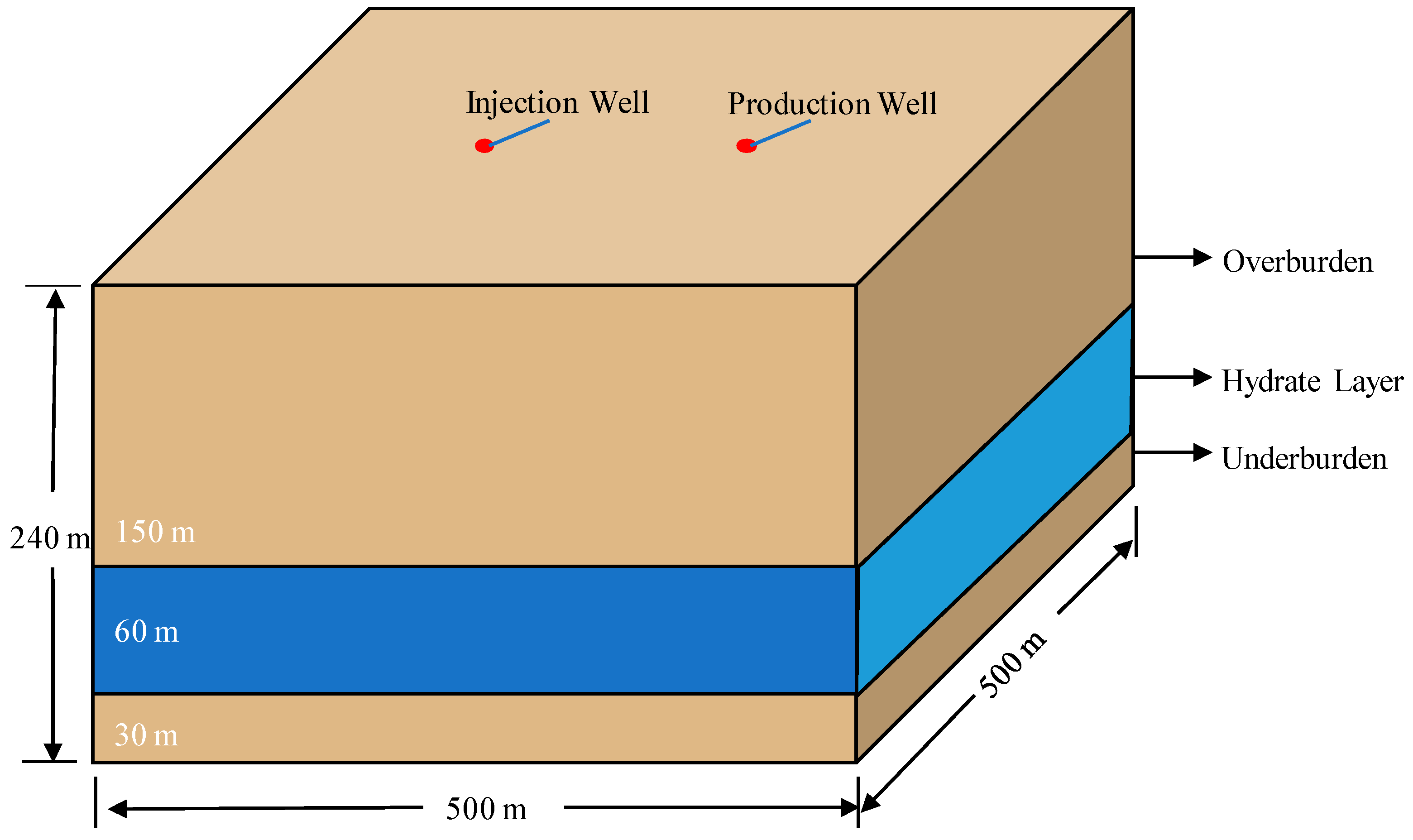
A three-dimensional NGH reservoir geological model with dimensions 500 m × 500 m × 240 m was setup. The NGH reservoir is divided into three layers vertically, including a 150 m layer representing overburden, a 60 m layer representing NGH reservoir, and a 30 m layer representing the underburden. Figure 3 shows a schematic diagram of the geological model. Two vertical wells are designed in the model with one functioning as a depressurization production well and the other as an injection well for CO2. The distance between two wells is 170 m. To avoid the interference of the water intrusion from the underburden, the production section of the two wells is located at the upper 50 m of the NGH layer.
Two simulation cases with different production strategies are conducted for comparison: Case A is designed using depressurization only with a bottom hole pressure (BHP) of 5.0 MPa; Case B is designed using the combination of depressurization and CO2 exchange method. In the initial 500 days of Case B, depressurization using a BHP of 5 MPa was employed, then CO2 was injected at a rate of 5000 m3·d−1. The maximum CO2 injection pressure is 18.0 MPa. The simulation time for both cases is set as 2000 days. Table 1 lists the main parameters of the thermophysical properties.

3.1. Analysis of Fluid Production

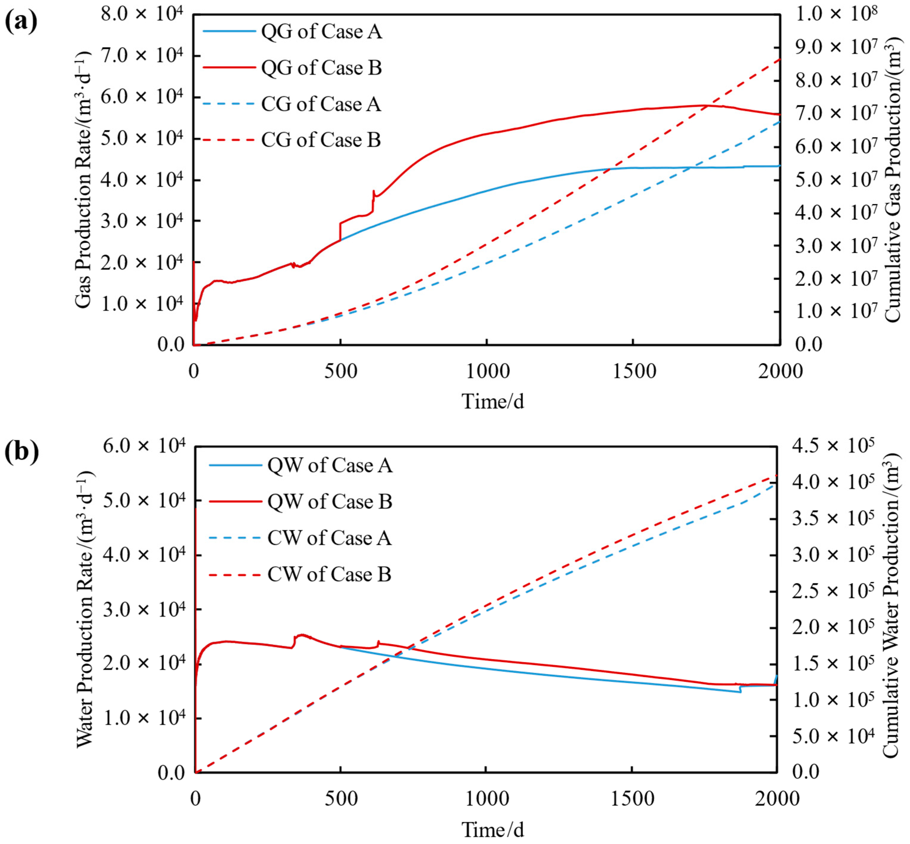
Figure 4 shows a comparison of the gas and water production (gas production rate QG, cumulative gas production CG, water production rate QW, cumulative water production CW) over time in the afore-mentioned two cases. It was observed that the dynamic of gas and water production shows an identical trend for the initial 500 days due to the same depressurization method applied. After the injection of CO2 starting at 500 days, the production rate of CH4 in Case B shows an immediately increasing trend compared with Case A as evidenced by the evolution of QG and CG. This can be explained by the increase of the pressure near the injection well due to CO2 injection, which drives the flow of the dissociated CH4 from NGH to the production well. A significant boost on the gas production rate was observed at about 610 d. This can be explained by the injected CO2 forming CO2 hydrate with the free water remaining in the reservoir or the dissociated water from NGH, and the heat released by the formation of CO2 hydrate promotes the dissociation of NGH further. This resulted in a significant increase in gas production only, but less of an increase in water production.
Based on the above analysis, the injection of CO2 and CO2 exchange promotes the dissociation of NGH. For a production period of 2000 days, CG and CW in Case B (depressurization coupled with CO2 exchange) increased by about 27.88% and 2.90%, respectively, compared with Case A (depressurization only).

3.2. Evolution of P, T, and Sh

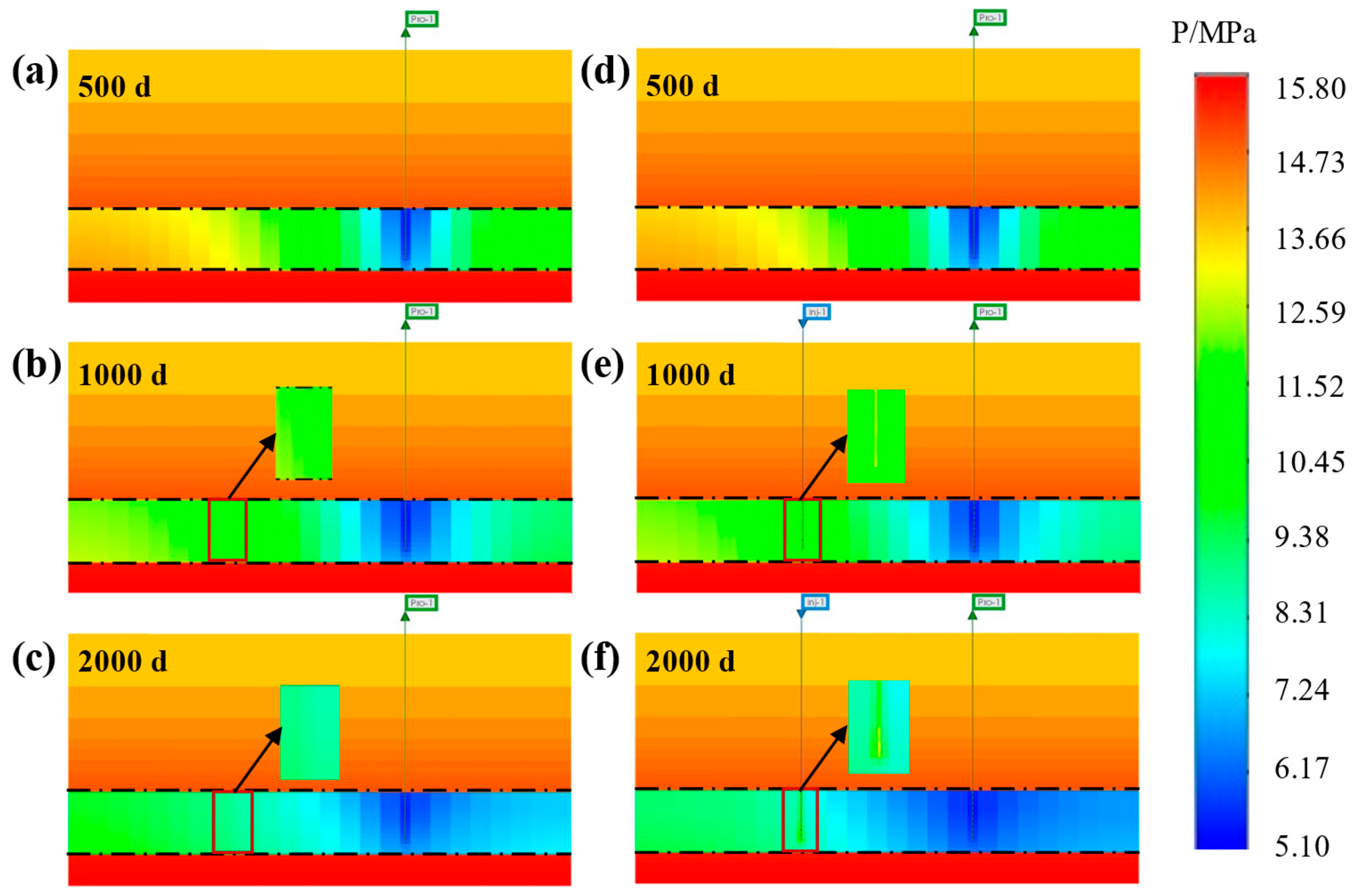
Figure 5 shows the evolution of P at 500 days, 1000 days, and 2000 days of production (left figure panel shows Case A using depressurization method and right figure panel shows Case B using depressurization with CO2 exchange method). P reduction spreads from the production well to the surroundings gradually. The fastest P drop (DP) located near the well and DP gradually decreases away from the well. With the increase of production time, the degree and the area affected by the pressure reduction gradually increase. Due to the permeability difference between the NGH layer (1100 × 10−3 μm2) and the overburden and underburden (1 × 10⁻³ μm2), pressure drop mainly propagates in the NGH layer.
In Case B, it is observed that P increases near the injection well due to CO2 injection. However, the formation of CO2 hydrate accelerates the dissociation of NGH, which possibly increases the porosity and permeability of the NGH reservoir. It further assists the pressure transmission in the NGH reservoir. This can be evidenced in Figure 5f at t = 2000 days, the area with P reduction is much wider and P near the production well is much lower than that in Case A (see Figure 5c).
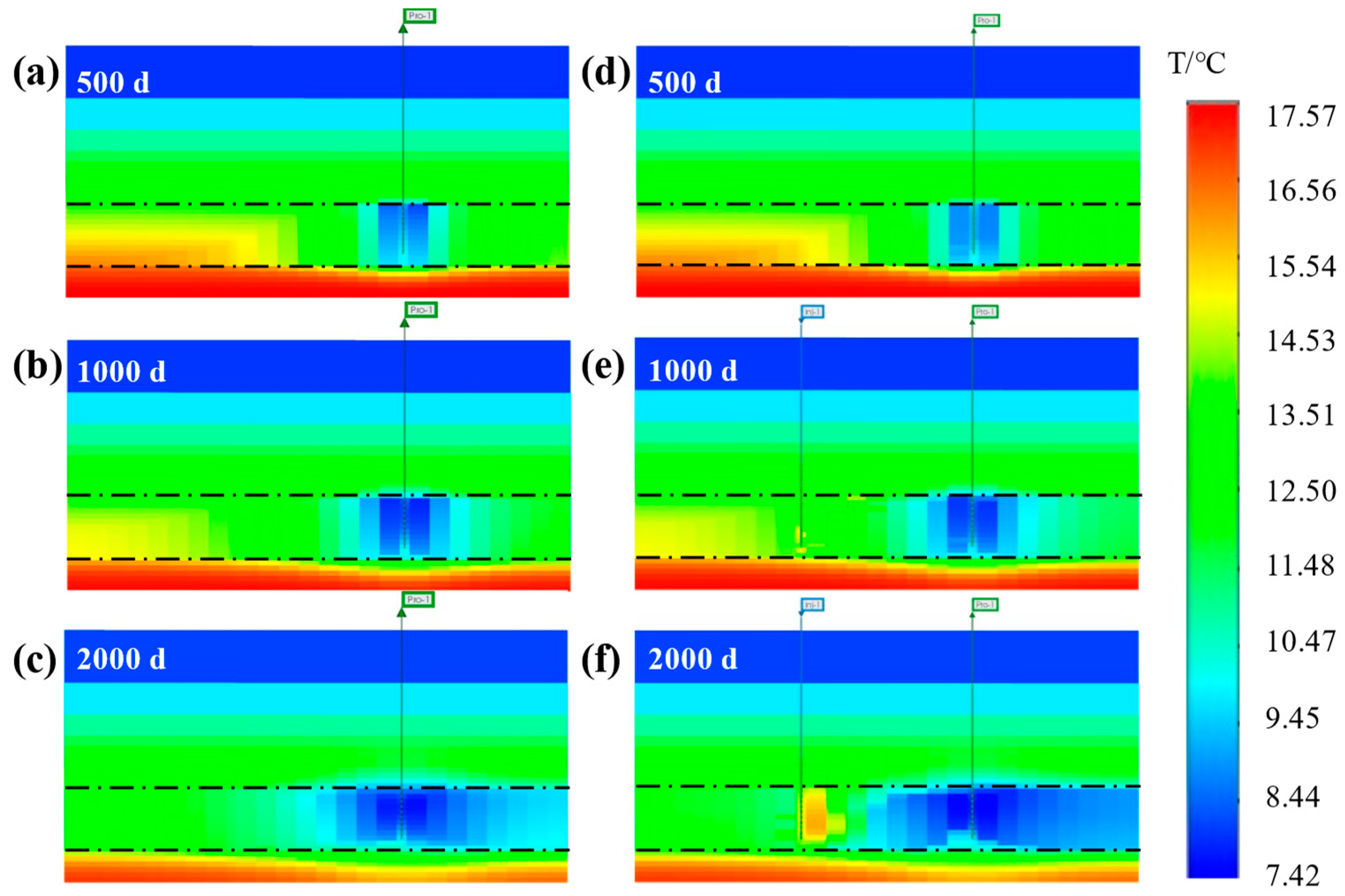
Figure 6 shows the evolution of T in Case A and Case B at t = 500 days, 1000 days, and 2000 days. Due to the endothermic process of NGH dissociation (DHCH4 = 54.5 kJ/mol), the T near the production well drops rapidly. The T drop is decreasing with the increasing distance away from the production well. The low-T region expands over time with the increasing area of NGH dissociation. In Case B, with the injection of CO2 and the formation of CO2 hydrate releasing heat (DHCO2 = 57.9 kJ/mol), T near the injection well increases and is relatively higher in this region. In addition, it was found that the direction of T increase is rightward from the injection well to the production well. This can be explained by the direction of CO2 exchange, which results in the unsymmetric T distribution near the injection well. Around the injection well, T is relatively higher towards the production well. On the other hand, due to the CO2 exchange results in a larger mass of NGH dissociation (an endothermic reaction), the T decrease near the production well is more significant in Case B compared with that in Case A at t = 2000 days. Overall, the T at the lower section of NGH reservoir is higher than that in the upper section based on the geothermal gradient.
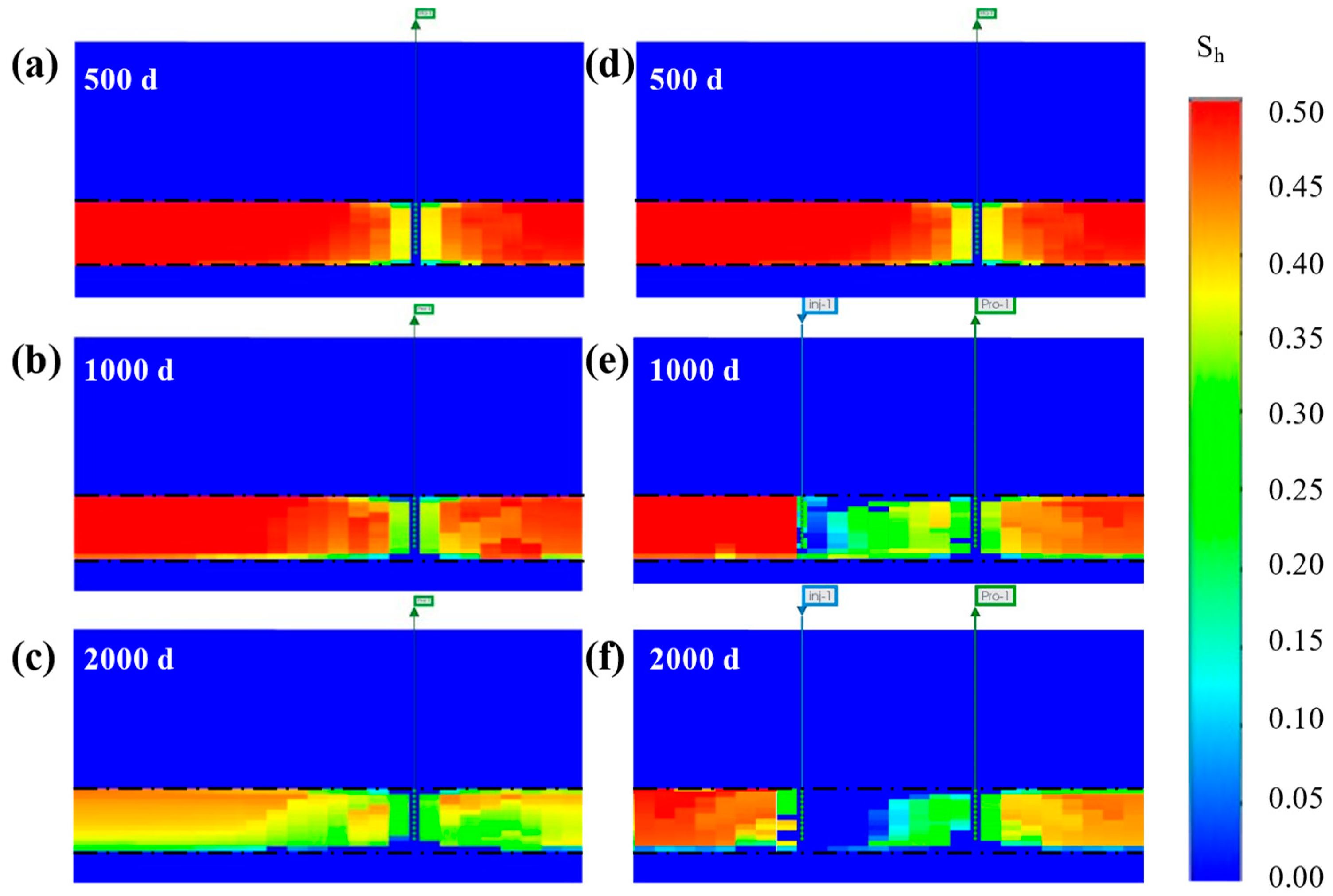
Figure 7 shows the evolution of NGH saturation in Case A and Case B at t = 500 days, 1000 days, and 2000 days. It can be informed that the dissociation of NGH propagates from the production well outward gradually. The region near the production well exhibits a faster dissociation rate compared with that far from the production well. Due to the geothermal gradient effect, NGH located at the lower section of the NGH reservoir practically dissociated more quickly than the upper section. In Case B, the dissociation rate of NGH near the injection well is enhanced with the injected CO2 forming CO2 hydrate and releasing heat. With the increasing amount of CO2 injected and transported, NGH located in between the injection well and the production well dissociated at a much faster rate. It should be noted that in Case A under the depressurization method, NGH dissociation is symmetric and propagates outward based on the center of production well. While in Case B, the majority of NGH dissociation occurs in the region in between two wells. Based on the above analysis, the distance between the injection well and the production well has a profound relationship with the fluid production performance, which need to be further optimized in future studies.
Figure 8 shows the evolution of CO2 hydrate saturation in Case A and Case B at t = 500 days, 1000 days, and 2000 days. It can be seen in Figure 8 that the formation of CO2 hydrate initially occurred near the injection well and expanded outward from the injection well to the production well. The majority of the CO2 hydrate is located in the region between the injection well and the production well. Due to the geothermal gradient, the saturation of CO2 hydrate in the upper section is practically higher than that in the lower section.

3.3. Effect of CO2 Exchange on NGH Reservoir Stability

On one hand, the formation of CO2 hydrate in the pore space increases the NGH reservoir stability. However, the exchange of CO2 further promotes the dissociation of NGH, which results in the weakening of the NGH reservoir stability. For a fair comparison of the effect of CO2 exchange on NGH reservoir stability, we compared the displacement of the NGH reservoir under the same CG = 5.81 × 10⁷ m3 in both cases. The production time is 1500 days in Case B compared with 1800 days in Case A, as shown in Figure 4a.
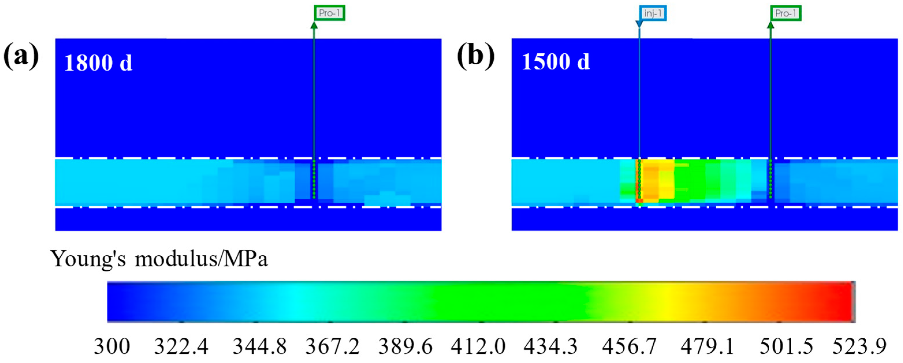
Figure 9 shows the comparison of the Young’s Modulus in two cases (left as Case A and right as Case B) with the same CG. In the case of depressurization only, due to the dissociation of NGH, Young’s modulus of the formation near the production well reduces, which reduces the reservoir capability to resist stress deformation. In Case B, although the dissociation of NGH reduces the formation strength partially, the formation of CO2 hydrate further improves the formation strength. The formation of CO2 hydrate increased Young’s modulus of hydrate-bearing sediments significantly between the two wells. This preserves the NGH reservoir’s ability to maintain its initial stability.
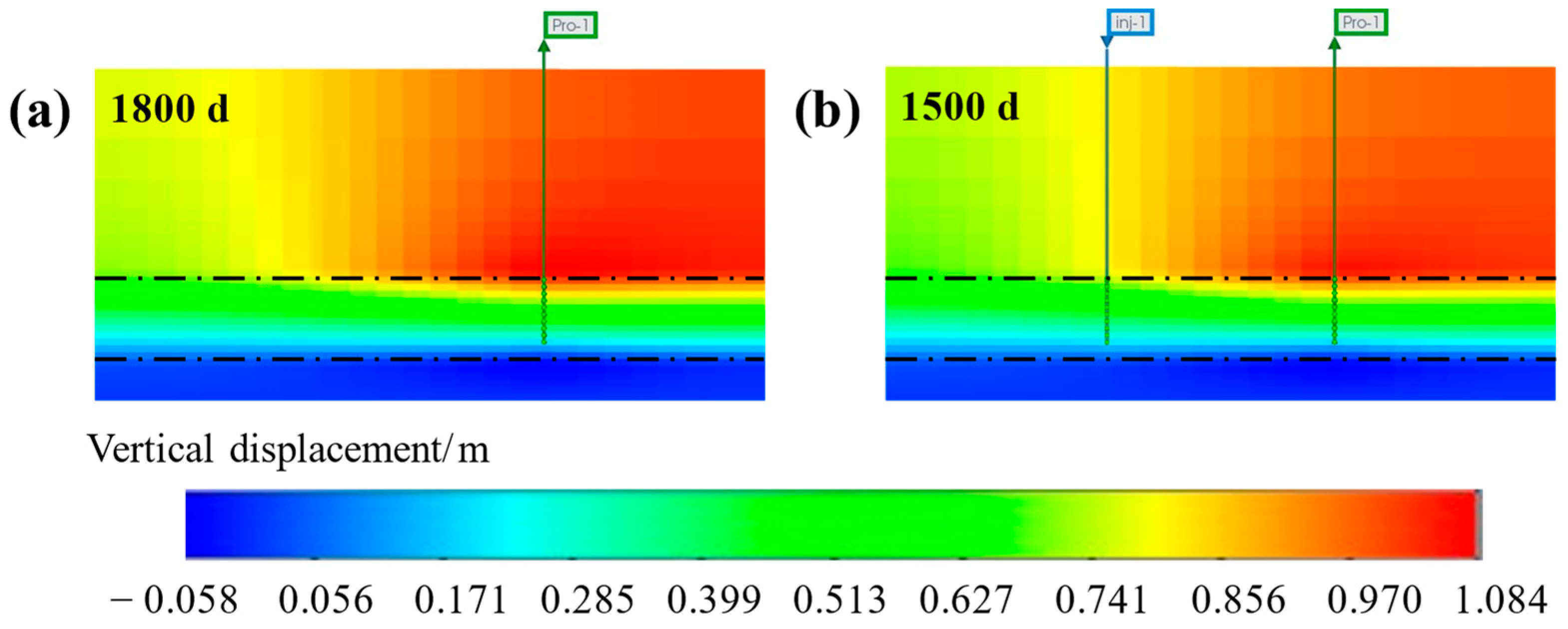
Figure 10 shows the comparison of NGH reservoir vertical displacement in both cases at the same CG. The positive value in the figure legend indicates the downward settlement of the formation and the negative value indicates the uplift of the formation. It was observed in Figure 10 that the maximum subsidence occurs at the interface of the overburden and NGH layer near the production well. The value of maximum subsidence is 1.06 m in Case B compared with that of 1.08 m in Case A. The maximum uplift occurs at the interface of the underburden and NGH layer near the production well. The uplift distance is 0.058 m in Case B compared with that of 0.057 m in Case A. Overall, the subsidence of the NGH reservoir using the method of depressurization coupled with CO2 exchange is less than that in the case of depressurization only. The simulation results indicated that NGH dissociation assisted by CO2 exchange practically offers an advantage for maintaining the reservoir stability.

4. Conclusions

This paper developed a combined numerical model of THMC (thermal-hydrodynamic-mechanical-chemical) to describe the behavior of gas production and reservoir reaction. Two different production scenarios have been employed for the simulation: depressurization and depressurization coupled with CO2 exchange. The results can be yielded as follows:
(a)
A coupled THMC numerical model was developed in this study for the description of the complex phase change behavior, the gas-water two-phase flow, heat transfer, and formation deformation associated with NGH field-scale production;
(b)
The simulation results suggested that the injection of CO2 promotes the dissociation of NGH compared with depressurization only. The cumulative production of gas and water increased by 27.88% and 2.90%, respectively based on 2000 days of production simulation;
(c)
In Case A (depressurization only), NGH dissociation is symmetric and propagates outward based on the center of production well. While in Case B (depressurization coupled with CO2 exchange), the majority of NGH dissociation occurs in the region between the injection well and the production well;
(d)
NGH reservoir subsidence propagates outward based on the center of the production well in both cases. The maximum subsidence occurs at the interface of the overburden and NGH layer near the production well. The maximum uplift occurs at the interface of the underburden and NGH layer at the production well;
(e)
The subsidence of the NGH reservoir is less in Case B (depressurization coupled with CO2 exchange) compared with that of Case A (depressurization only) at the same cumulative gas production. The results suggest CO2 exchange in the NGH reservoirs alleviates the issue of reservoir subsidence during production and maintains good reservoir stability.
The results of this study can provide a new insight for high-efficient and safe gas extraction from marine deposits of NGH.

Author Contributions

Writing—original draft preparation, Q.L.; writing—review and editing, S.L. (Shuxia Li); investigation, S.D.; validation, Z.Y.; visualization, L.L. and S.L. (Shuaijun Li). All authors have read and agreed to the published version of the manuscript.

Funding

This research was funded by the National Key R&D Program of China (2021YFC2800903) and the National Natural Science Foundation of China (Nos. 52074334, 51991365).

Data Availability Statement

All data are presented in the paper.

Conflicts of Interest

The authors declare that they have no known competing financial interests or personal relationships that could have appeared to influence the work reported in this paper.

References

  1. Chong, Z.R.; Yang, S.H.B.; Babu, P.; Linga, P.; Li, X.-S. Review of natural gas hydrates as an energy resource: Prospects and challenges. Appl. Energy 2016, 162, 1633–1652. [Google Scholar] [CrossRef]
  2. Yin, Z.; Chong, Z.R.; Tan, H.K.; Linga, P. Review of gas hydrate dissociation kinetic models for energy recovery. J. Nat. Gas Sci. Eng. 2016, 35, 1362–1387. [Google Scholar] [CrossRef]
  3. Qiu, S.; Wang, G. Effects of Reservoir Parameters on Separation Behaviors of the Spiral Separator for Purifying Natural Gas Hydrate. Energies 2020, 13, 5346. [Google Scholar] [CrossRef]
  4. Wang, Y.; Ning, Y.; Wang, Y. Fractional Time Derivative Seismic Wave Equation Modeling for Natural Gas Hydrate. Energies 2020, 13, 5901. [Google Scholar] [CrossRef]
  5. Ren, J.; Liu, X.; Niu, M.; Yin, Z. Effect of sodium montmorillonite clay on the kinetics of CH4 hydrate—Implication for energy recovery. Chem. Eng. J. 2022, 437, 135368. [Google Scholar] [CrossRef]
  6. Lee, T.; Lee, J.Y.; Ahn, T.; Son, H.A. Numerical Simulation of Gas Hydrate Production Using the Cyclic Depressurization Method in the Ulleung Basin of the Korea East Sea. Appl. Sci. 2021, 11, 9748. [Google Scholar] [CrossRef]
  7. Zhou, S.; Chen, W.; Li, Q.; Zhou, J.; Shi, H. Research on the solid fluidization well testing and production for shallow non-diagenetic natural gas hydrate in deep water area. China Offshore Oil Gas 2017, 29, 1–8. [Google Scholar]
  8. Qin, X.; Lu, C.; Wang, P.; Liang, Q. Hydrate phase transition and seepage mechanism during natural gas hydrates production tests in the South China Sea: A review and prospect. China Geol. 2022, 2, 201–217. [Google Scholar] [CrossRef]
  9. Zhou, S.; Li, Q.; Lv, X.; Pang, W.; Fu, Q. Thinking and suggestions on research direction of natural gas hydrate development. China Offshore Oil Gas 2019, 31, 1–8. [Google Scholar]
  10. Cao, X.; Wang, H.; Yang, K.; Wu, S.; Chen, Q.; Bian, J. Hydrate-based CO2 sequestration technology: Feasibilities, mechanisms, influencing factors, and applications. J. Pet. Sci. Eng. 2022, 2022, 111121. [Google Scholar] [CrossRef]
  11. Song, Y.; Wang, S.; Cheng, Z.; Huang, M.; Zhang, Y.; Zheng, J.; Jiang, L.; Liu, Y. Dependence of the hydrate-based CO2 storage process on the hydrate reservoir environment in high-efficiency storage methods. Chem. Eng. J. 2021, 415, 128937. [Google Scholar] [CrossRef]
  12. Makogon, Y.F.; Holditch, S.A.; Makogon, T.Y. Russian field illustrates gas-hydrate production. Oil Gas J. 2005, 103, 43–47. [Google Scholar]
  13. Grover, T.; Holditch, S.A.; Moridis, G. Analysis of Reservoir Performance of Messoyakha Gas Hydrate Field. In Proceedings of the SPE Annual Technical Conference and Exhibition, Denver, USA, 21–24 September 2008. SPE-114375-MS. [Google Scholar]
  14. Makogon, Y.F.; Omelchenko, R.Y. Commercial gas production from Messoyakha deposit in hydrate conditions. J. Nat. Gas Sci. Eng. 2013, 11, 1–6. [Google Scholar] [CrossRef]
  15. Ye, H.; Wu, X.; Li, D. Numerical Simulation of Natural Gas Hydrate Exploitation in Complex Structure Wells: Productivity Improvement Analysis. Mathematics 2021, 9, 2184. [Google Scholar] [CrossRef]
  16. Li, L.; Li, X.; Wang, Y.; Qin, C.; Li, B.; Luo, Y.; Feng, J. Investigating the Interaction Effects between Reservoir Deformation and Hydrate Dissociation in Hydrate-Bearing Sediment by Depressurization Method. Energies 2021, 14, 548. [Google Scholar] [CrossRef]
  17. Kurihara, M.; Sato, A.; Funatsu, K.; Ouchi, H.; Yamamoto, K.; Numasawa, M.; Ebinuma, T.; Narita, H.; Masuda, Y.; Dallimore, S.R.; et al. Analysis of Production Data for 2007/2008 Mallik Gas Hydrate Production Tests in Canada. In Proceedings of the International Oil and Gas Conference and Exhibition in China, Beijing, China, 8–10 June 2010. SPE-132155-MS. [Google Scholar]
  18. Fujii, T.; Takayama, T.; Nakamizu, M.; Yamamoto, K.; Dallimore, S.R.; Mwenifumbo, J.; Wright, J.F.; Kurihara, M.; Sato, A.; Al-Jubori, A. Wire-line logging analysis of the 2007 JOGMEC/NRCAN/AURORA Mallik gas hydrate production test well. In Proceedings of the 6th International Conference on Gas Hydrates (ICGH 2008), Vancouver, BC, Canada, 6–10 July 2008. [Google Scholar]
  19. Zhang, J.; Liu, X.; Chen, D.; Yin, Z. An investigation on the permeability of hydrate-bearing sediments based on pore-scale CFD simulation. Int. J. Heat Mass Transf. 2022, 192, 122901. [Google Scholar] [CrossRef]
  20. Schoderbek, D.; Martin, K.L.; Howard, J.; Silpngarmlert, S.; Hester, K. North slope hydrate fieldtrial: CO2/CH4 exchange. In Proceedings of the OTC Arctic Technology Conference, Houston, TX, USA, 3–5 December 2012. OTC-23725-MS. [Google Scholar]
  21. Zhu, Y.; Zhang, Y.; Sun, Z. Overview on permafrost gas hydrate exploration in China. In Proceedings of the 8th International Conference on Gas Hydrate, Beijing, China, 28 July–1 August 2014. [Google Scholar]
  22. Zhu, Y.; Pang, S.; Wang, P.; Zhang, S.; Xiao, R. A review of the resource potentials and test productions of natural gas hydrates in China. Sediment. Geol. Tethyan Geol. 2021, 41, 524–535. [Google Scholar]
  23. Yamamoto, K. Methane hydrate offshore production test in the eastern Nankai Trough: A milestone on the path to real energy resource. In Proceedings of the 8th International Conference on Gas Hydrate, Beijing, China, 28 July–1 August 2014. [Google Scholar]
  24. Konno, Y.; Fujii, T.; Sato, A.; Akamine, K.; Naiki, M.; Masuda, Y.; Yamamoto, K.; Nagao, J. Key findings of the world’s first offshore methane hydrate production test off the coast of Japan: Toward future commercial production. Energy Fuels 2017, 31, 2607–2616. [Google Scholar] [CrossRef]
  25. Yamamoto, K.; Wang, X.-X.; Tamaki, M.; Suzuki, K. The second offshore production of methane hydrate in the Nankai Trough and gas production behavior from a heterogeneous methane hydrate reservoir. RSC Adv. 2019, 9, 25987–26013. [Google Scholar] [CrossRef] [PubMed] [Green Version]
  26. Ye, J.-L.; Qin, X.-W.; Qiu, H.-J.; Liang, Q.-Y.; Dong, Y.-F.; Wei, J.-G.; Lu, H.-L.; Lu, J.-A.; Shi, Y.-H.; Zhong, C. Preliminary results of environmental monitoring of the natural gas hydrate production test in the South China Sea. China Geol. 2018, 1, 202–209. [Google Scholar] [CrossRef]
  27. Ye, J.; Qin, X.; Xie, W.; Lu, H.; Ma, B.; Qiu, H.; Liang, J.; Lu, J.; Kuang, Z.; Lu, C. Main progress of the second gas hydrate trial production in the South China Sea. Geol. China 2020, 47, 557–568. [Google Scholar]
  28. Lu, H.; Shang, S.; Chen, X.; Qin, X.; Gu, L.; Qiu, H. Research progress and development direction of numerical simulator for natural gas hydrate development. Acta Pet. Sin. 2021, 42, 1516. [Google Scholar]
  29. Gaddipati, M. Code Comparison of Methane Hydrate Reservoir Simulators Using CMG STARS. Master’s Thesis, West Virginia University, Morgantown, WV, USA, 2008. [Google Scholar]
  30. Uddin, M.; Coombe, D.; Law, D.; Gunter, B. Numerical studies of gas hydrate formation and decomposition in a geological reservoir. J. Energy Resour. Technol. 2008, 130, 3. [Google Scholar] [CrossRef]
  31. Anderson, B.J.; Wilder, J.W.; Kurihara, M.; White, M.D.; Moridis, G.J.; Wilson, S.J.; Pooladi-Darvish, M.; Masuda, Y.; Collett, T.S.; Hunter, R. Analysis of modular dynamic formation test results from the Mount Elbert 01 stratigraphic test well, Milne Point Unit, North Slope, Alaska. Marine Pet. Geol. 2008, 28, 2. [Google Scholar]
  32. Lamedo, M.A.; Provero, D.; Viloria, A.; Yánez, G. Gas production from hydrates dissociation in marine sediments. In Proceedings of the SPE Latin American and Caribbean Petroleum Engineering Conference, Lima, Peru, 1–3 December 2010. SPE-139306-MS. [Google Scholar]
  33. Reagan, M.T.; Moridis, G.J.; Johnson, J.N.; Pan, L.; Freeman, C.M.; Boyle, K.L.; Keen, N.D.; Husebo, J. Field-scale simulation of production from oceanic gas hydrate deposits. Transp. Porous Media 2015, 108, 151–169. [Google Scholar] [CrossRef]
  34. Myshakin, E.M.; Gaddipati, M.; Rose, K.; Anderson, B.J. Numerical simulations of depressurization-induced gas production from gas hydrate reservoirs at the Walker Ridge 313 site, northern Gulf of Mexico. Marine Pet. Geol. 2012, 34, 169–185. [Google Scholar] [CrossRef]
  35. Li, S.; Ding, S.; Wu, D.; Wang, X.; Hao, Y.; Li, Q.; Pang, W. Analysis of stratum subsidence induced by depressurization at an offshore hydrate-bearing sediment. Energy Fuels 2021, 35, 1381–1388. [Google Scholar] [CrossRef]
  36. Li, S.; Wu, D.; Wang, Z.; Liu, J.; Xie, Y. Numerical simulation of dissociation front of Shenhu hydrate reservoirs by depressurization. Scientia Sinica Phys. Mech. Astron. 2019, 49, 034609. [Google Scholar] [CrossRef] [Green Version]
  37. Li, S.; Li, S.; Zheng, R.; Li, Q.; Pang, W. Strategies for gas production from Class 2 hydrate accumulations by depressurization. Fuel 2021, 286, 119380. [Google Scholar] [CrossRef]
  38. CMG. Stars User Guide; Computer Modelling Group Ltd.: Calgary, AB, Canada, 2015. [Google Scholar]
  39. Li, G. Numerical investigation of CO2 storage in hydrocarbon field using a geomechanical-fluid coupling model. Petroleum 2016, 2, 252–257. [Google Scholar] [CrossRef] [Green Version]
  40. Al-Mudhafer, W.J.; Zein Al-Abideen, M.J. Comparative evaluation of a heterogeneous light oil reservoir performance: Thermal IOR simulation, bitumen extraction, and associated geomechanical deformation. In Proceedings of the SPE Arctic and Extreme Environments Technical Conference and Exhibition, Moscow, Russia, 15–17 October 2013. [Google Scholar]
  41. Varre, S.B.; Siriwardane, H.J.; Gondle, R.K.; Bromhal, G.S.; Chandrasekar, V.; Sams, N. Influence of geochemical processes on the geomechanical response of the overburden due to CO2 storage in saline aquifers. Int. J. Greenh. Gas Control 2015, 42, 138–156. [Google Scholar] [CrossRef] [Green Version]
  42. Lin, T.-K.; Hsieh, B.-Z. Prevention of seabed subsidence of class-1 gas hydrate deposits via CO2-EGR: A numerical study with coupled geomechanics-hydrate reaction-multiphase fluid flow model. Energies 2020, 13, 1579. [Google Scholar] [CrossRef] [Green Version]
  43. Kim, H.; Bishnoi, P.R.; Heidemann, R.A.; Rizvi, S.S. Kinetics of methane hydrate decomposition. Chem. Eng. Sci. 1987, 42, 1645–1653. [Google Scholar] [CrossRef]
  44. Clarke, M.A.; Bishnoi, P.R. Measuring and modelling the rate of decomposition of gas hydrates formed from mixtures of methane and ethane. Chem. Eng. Sci. 2001, 56, 4715–4724. [Google Scholar] [CrossRef]
  45. Kamath, V.A. Study of Heat Transfer Characteristics during Dissociation of Gas Hydrates in Porous Media. Ph.D. Thesis, University of Pittsburgh, Pittsburgh, PA, USA, 1984. [Google Scholar]
  46. Goel, N. In situ methane hydrate dissociation with carbon dioxide sequestration: Current knowledge and issues. J. Pet. Sci. Eng. 2006, 51, 169–184. [Google Scholar] [CrossRef]
  47. Tran, D.; Nghiem, L.; Buchanan, L. Aspects of coupling between petroleum reservoir flow and geomechanics. In Proceedings of the 43rd US Rock Mechanics Symposium & 4th US-Canada Rock Mechanics Symposium, Asheville, NC, USA, 28 June–1 July 2009. ARMA-09-089. [Google Scholar]
  48. Tran, D.; Buchanan, L.; Nghiem, L. Improved gridding technique for coupling geomechanics to reservoir flow. SPE J. 2010, 15, 64–75. [Google Scholar] [CrossRef]
  49. Aziz, K.; Ramesh, A.; Woo, P. Fourth SPE comparative solution project: Comparison of steam injection simulators. J. Pet. Technology 1987, 39, 1576–1584. [Google Scholar] [CrossRef]
  50. Ran, Q.-Q.; Li, S.-L. Study on dynamic models of reservoir parameters in the coupled simulation of multiphase flow and reservoir deformation. Pet. Explor. Dev. 1997, 24, 61–65. [Google Scholar]
  51. Moridis, G.J.; Queiruga, A.F.; Reagan, M.T. Simulation of gas production from multilayered hydrate-bearing media with fully coupled flow, thermal, chemical and geomechanical processes using TOUGH+ Millstone. Part 1: Numerical modeling of hydrates. Transp. Porous Media 2019, 128, 405–430. [Google Scholar] [CrossRef]
  52. Lin, T.-K. Numerical Simulation Study of CO2 Enhanced Gas Recovery in Class 1 Gas Hydrate Deposits Offshore Southwestern Taiwan. Master’s Thesis, National Cheng Kung University, Tainan, China, 2019. [Google Scholar]
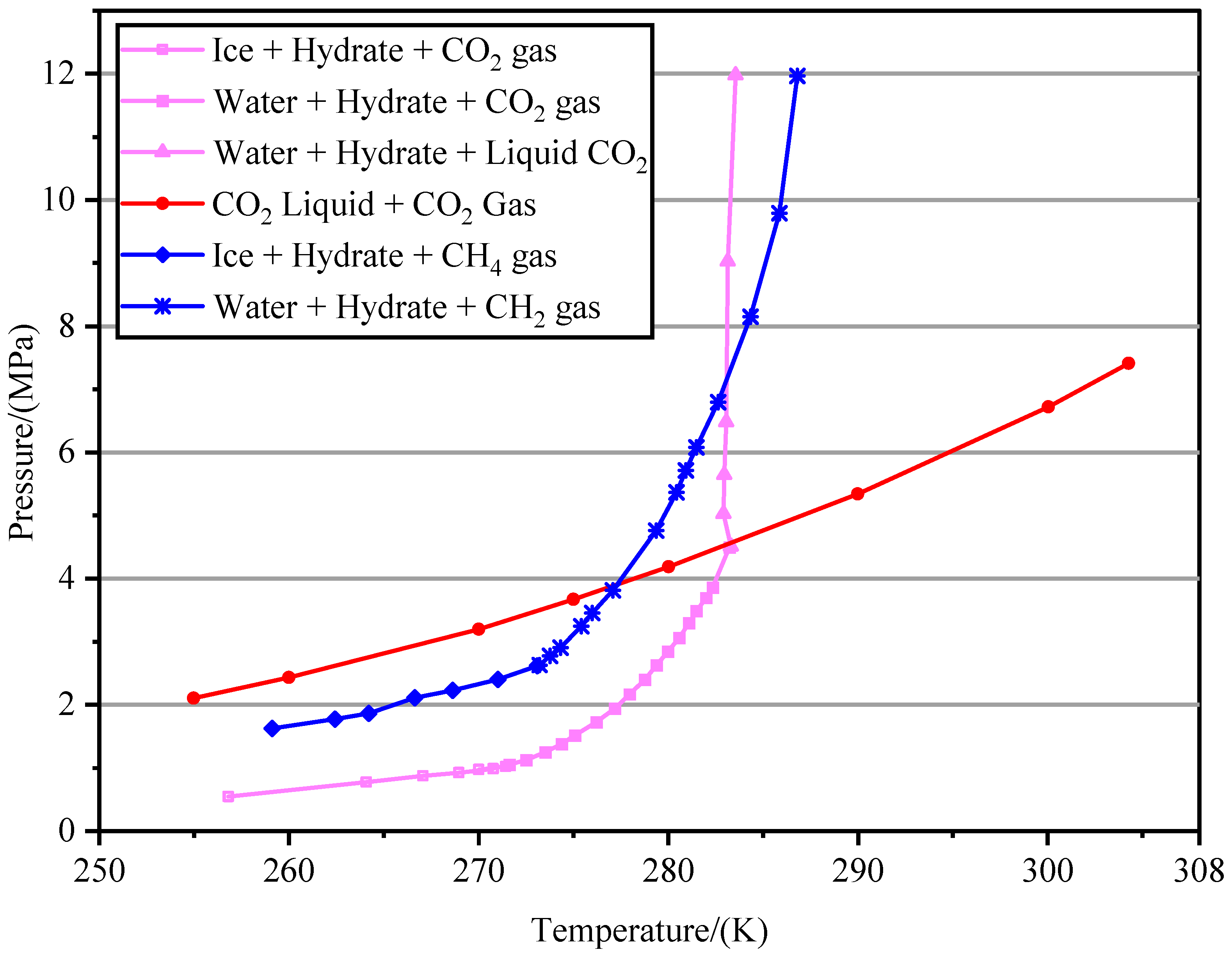
Figure 1. Phase equilibrium relation of CO2 and CH4 hydrate in this study.
Energies 15 08968 g001
Figure 2. Flow chart of the iterative solution approach of the THMC model.
Energies 15 08968 g002
Figure 3. Schematic diagram of the geological model.
Energies 15 08968 g003
Figure 4. Comparison of gas (a) and water (b) production in Case A (depressurization only) and Case B (depressurization coupled with CO2 exchange).
Energies 15 08968 g004
Figure 5. Evolution of P after 500 days, 1000 days, 2000 days ((ac) for Case A and (df) for Case B).
Energies 15 08968 g005
Figure 6. Evolution of T after 500 days, 1000 days, 2000 days ((ac) for Case A and (df) for Case B).
Energies 15 08968 g006
Figure 7. Evolution of NGH saturation after 500 days, 1000 days, 2000 days ((ac) for Case A and (df) for Case B).
Energies 15 08968 g007
Figure 8. Evolution of CO2 hydrate saturation after 500 days (a), 1000 days (b), 2000 days (c).
Energies 15 08968 g008
Figure 9. Comparison of the Young’s Modulus in Case A (a) and Case B (b) with the same CG.
Energies 15 08968 g009
Figure 10. Comparison of the vertical displacement in Case A (a) and Case B (b) with the same CG.
Energies 15 08968 g010
Table 1. The main parameters used in the numerical simulation.
Parameter & UnitValueParameter & UnitValue
Grain density/(kg·m−3)2650NGH layer temperature/℃15.15
Intrinsic permeability of overburden/(10−3 μm2)1 × 10⁻⁶Pressure of hydrate layer/MPa15.23
Intrinsic permeability of NGH layer/(10−3 μm2)1100Relative permeability index n3.572
Intrinsic permeability of underburden/(10−3 μm2)1 × 10⁻⁶Irreducible water saturation SirA0.30
Porosity of overburden0.10Residual gas saturation SirG0.015
Porosity of NGH layer0.38Young’s modulus of the matrix/MPa300
Porosity of underburden0.10Young’s modulus of the natural gas hydrate/MPa500
Initial hydrate saturation in NGH layer0.50Young’s modulus of the CO2 hydrate/MPa800
Water saturation in NGH layer0.50Poisson’s ratio0.3
NGH density/(kg·m−3)920Friction angle30°
Publisher’s Note: MDPI stays neutral with regard to jurisdictional claims in published maps and institutional affiliations.