1. Introduction
A power conversion system (PCS) is used to connect a power supply with a battery energy storage system (BESS); it requires voltage conversion and bidirectional power transmission. A PCS can be used to realize ‘power peak shaving and power valley filling’ in a power system [
1,
2,
3,
4,
5]. With the development of distributed generation, a percentage of a BESS can eliminate power fluctuation, and it can also improve the grid’s power quality and stability [
6,
7].
When a PCS is connected to an AC grid, it needs a single-stage DC/AC converter or a two-stage DC/DC converter cascaded with a DC/AC converter. Whether in a single-stage or two-stage converter, a PCS processes full battery power. A single-stage converter has the advantages of simpler implementation and lower cost; the tree-phase two-level converter has been widely used in PCS applications [
8]. To improve its rated voltage and power quality, the neutral point clamped (NPC) three-level converter and multilevel converters, such as a flying capacitor multilevel converter and a modular multilevel converter (MMC), were subsequently adopted [
9,
10].
A two-stage converter should be used when the battery voltage cannot match the converter’s requirements. In many references, resonant soft switching technology has been studied to improve a PCS’s efficiency [
11,
12,
13]; however, all these studies were based on full-power PCS. The full battery power is transmitted through the PCS, and power loss is still non-ignorable, no matter what type of soft switching technology is adopted.
Traditionally, a PCS transmits full battery power regardless of battery voltage variation. On the other hand, when the battery’s state of charge (SOC) changes significantly during the charging or discharging process, the battery voltage change is relatively small. For example, in a lithium iron phosphate battery, when the battery’s SOC changes from 80% to 20%, the battery’s voltage changes only 0.09 V, which is approximately 2.82% of its rated voltage (3.2 V) [
14]; this means that the difference between the converter’s input and output voltages is very small.
Considering the battery behavior of voltage and SOC, a fractional power processing or partial power processing architecture was proposed [
15,
16,
17,
18]. A converter was series connected with a battery to process a fraction of the DC voltage; hence, the converter power was also greatly reduced. In [
15,
16,
17], unipolar biasing voltage converters were studied, but applications were restricted by their unipolar characteristics. In [
18], a bipolar voltage-based fractional power converter achieved lower power processing; however, as only some theoretical analysis was provided, it requires a strong physical verification.
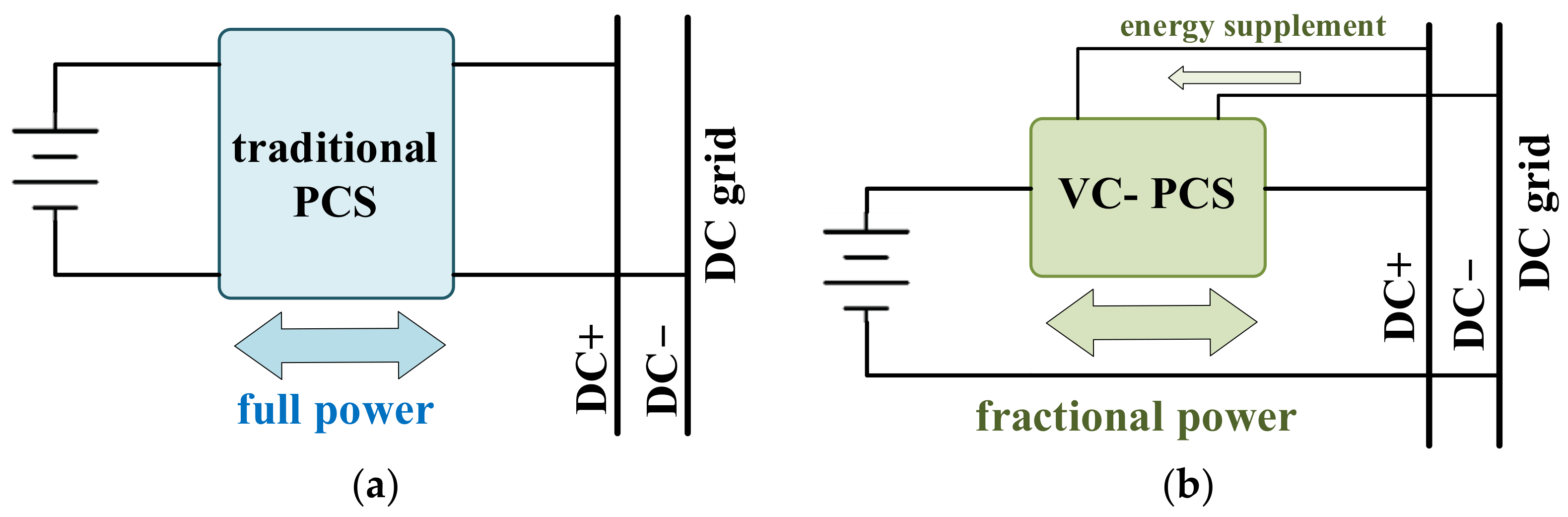
So far, there is no comprehensive research regarding bipolar partial power converters, including theoretical analysis, simulation, and experimental verifications. A voltage compensation and energy supplement-based PCS (VC-PCS) is studied in this paper. As shown in
Figure 1, it was series connected with a battery to compensate for voltage variation, and only processed fractional battery power. In addition, it needed auxiliary power to supplement energy.
During the charging process, when the battery voltage was higher than the DC grid voltage, the VC-PCS output negative voltage to compensate for the battery voltage increase and supplemented energy loss at the same time. During the discharging process, when the battery voltage was lower than the DC grid voltage, the VC-PCS output positive voltage to compensate for the battery voltage decrease and supplemented energy loss at the same time. In other words, the VC-PCS could charge and discharge the battery whether the battery voltage was higher or lower than the DC grid voltage.
This remainder of this paper is organized as follows. In
Section 2 and
Section 3, the VC-PCS topology and operation principle are introduced and thoroughly analyzed.
Section 4 presents the controller design and the control diagram. In
Section 5 and
Section 6, results of simulations and prototype experiments are presented, respectively. Finally,
Section 7 concludes the paper.
2. PCS with Voltage Compensation and Energy Supplement
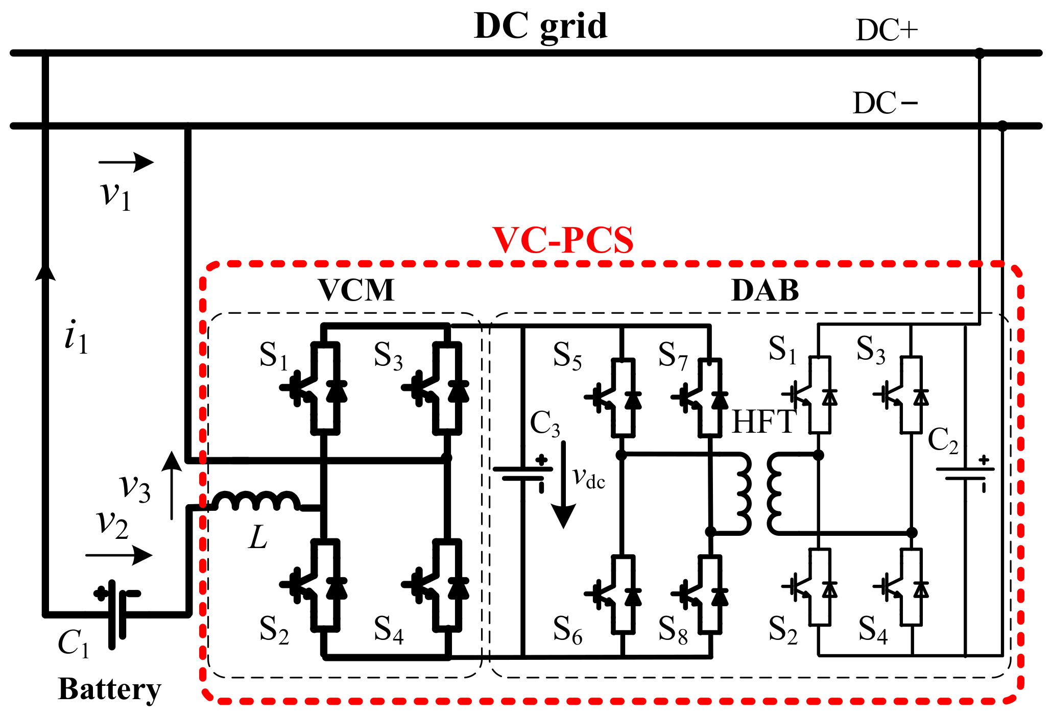
Figure 2 shows the proposed VC-PCS topology; the VC-PCS consisted of a voltage compensation modular converter (VCM) and a dual active bridge converter (DAB). The VCM was composed of a full bridge (FB) converter (S1–S4) and an inductor
L; the VCM generated bipolar voltage, and the inductor filtered current. The DAB provided stable DC voltage for the VCM, and functioned as a current commutation path and energy supplement unit.
According to working state and voltage differences between the battery and the DC grid, the VCM operated in four different states:
(1) CCC: constant current (or voltage) charging state.
(2) CCD: constant current discharging state.
(3) CCC-NVC: CCC with negative voltage compensation.
(4) CCD-PVC: CCD with positive voltage compensation.
3. Principle Analysis
Clearly stated, the DAB could be equivalent to a constant bidirectional DC power vdc. According to the working state and battery voltage, the principled analysis is given as follows.
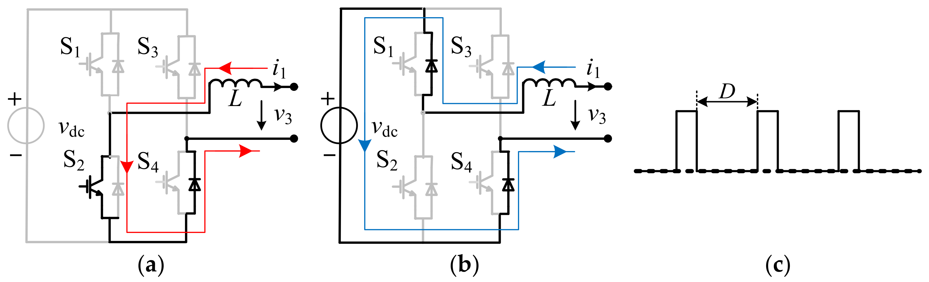
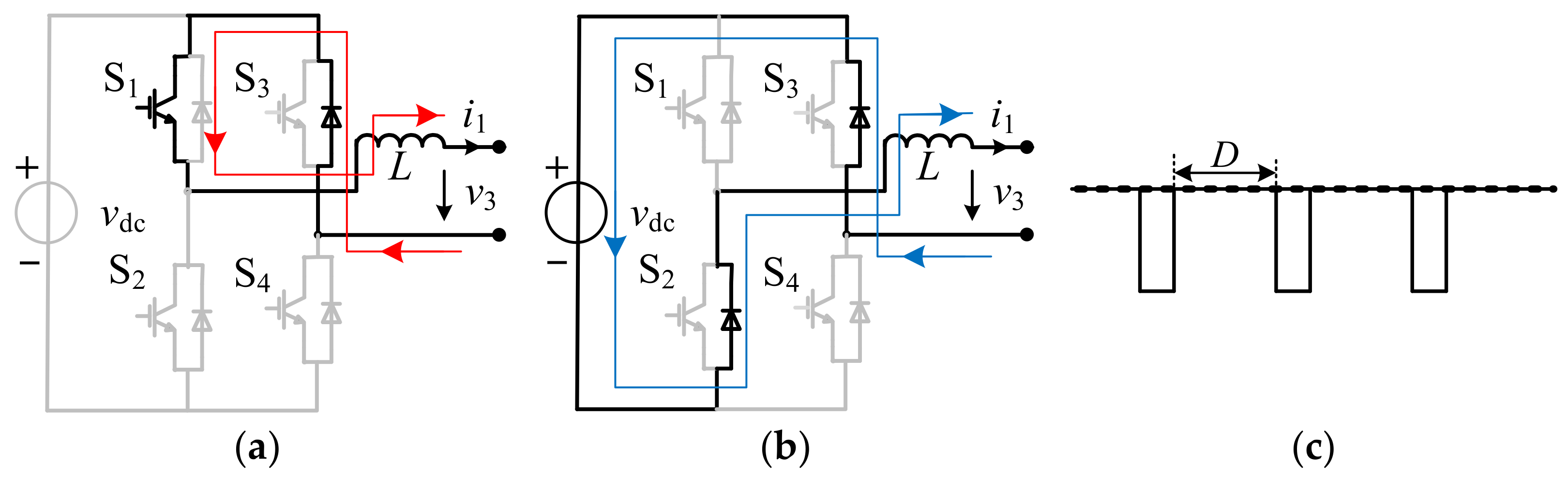
3.1. CCC State Analysis
In charging state (i1 < 0), if the battery voltage is lower than normal (v2 < v1), the CCC can be realized without voltage compensation, and it only needs to control the charging current.
As shown in
Figure 3a,b, when S
2 is on, the current flows along
L-S
2-S
4D, and the FB voltage is 0. When S
2 is off, the current flows through
L-S
1D-
vdc-S
4D, the current is commuted to reduce current ripple, energy is fed back to the DC power, and the FB voltage is
vdc.
Figure 3c shows the FB voltage; it is a positive pulse wave, and the VCM voltage satisfies
where
D1 is the duty ratio of S
2, and the current increases with an increase in the duty cycle; so, the current can be positively controlled by the duty cycle.
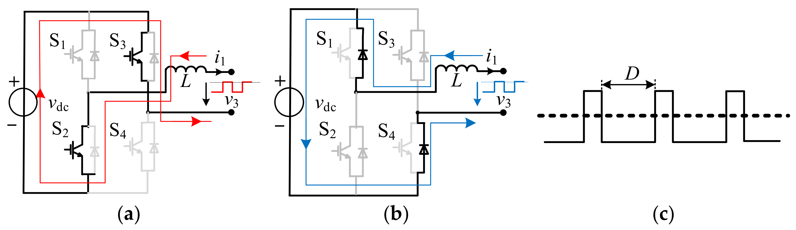
3.2. CCC-NVC State Analysis
In charging state (i1 < 0), if the battery voltage is higher than normal (v2 > v1), a negative voltage is needed to realize battery charging, i.e., v3 < 0 and v2 + v3 = v1; the VCM power is positive, so the VCM supplements energy to the battery.
As shown in
Figure 4a,b, when S
2 and S
3 are both on, the current flows through
L-S
2-
vdc-S
3, the DC power supplements energy to the battery, and the FB voltage is -
vdc. When S
2 and S
3 are both off, the current flows through
L-S
1D-
vdc-S
4D, the current is commuted to reduce current ripple, energy is fed back to the DC power, and the FB voltage is
vdc.
Figure 4c shows the FB voltage in the CCC-NVC state; the FB voltage is a positive or negative pulse wave, and the VCM voltage satisfies
where
D2 is the duty ratio of S
2 and S
3, and the current increases with an increase in the duty cycle; so, the current can be positively controlled by the duty cycle.
3.3. CCD State Analysis
In discharging state (i1 > 0), if the battery voltage is higher than normal (v2 > v1), the CCD can be realized without voltage compensation.
As shown in
Figure 5a,b, when S
1 is on, the current flows along S
3D-S
1-
L, and the FB voltage is 0. When S
1 is off, the current flows through S
3D-
vdc-S
2D-
L, the current is commuted to reduce current ripple, energy is fed back to the power, and the FB voltage is -
vdc.
Figure 5c shows the FB voltage in the CCD state; the FB voltage is a negative pulse wave, and the VCM voltage can be described by (1). Similarly, the current can be positively controlled by the duty cycle.
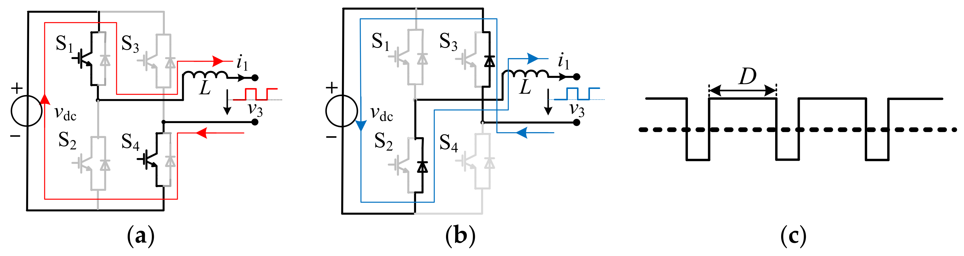
3.4. CCD-PVC State Analysis
In discharging state (i1 > 0), if the battery voltage is lower than normal (v2 < v1), a positive voltage is needed to realize battery discharging, i.e., v3 > 0 and v2 + v3 = v1; the VCM power is also positive, so the VCM supplements energy to the DC grid.
As shown in
Figure 6a,b, when S
1 and S
4 are both on, the current path is S
4-
vdc -S
1-
L, the DC power supplements energy to the DC grid, and the FB voltage is
vdc. When S
1 and S
4 are both off, the current is commuted to reduce current ripple, energy is fed back to the DC power, and the FB voltage is -
vdc.
Figure 6c shows the FB voltage in the CCD-PVC state; the FB voltage is a positive or negative pulse wave, and the VCM voltage can be described by (2). Similarly, the current can be positively controlled by the duty cycle.
4. Controller Design
According to the above analysis, switches S1 and S4 are always off in the charging state; if the battery voltage is lower than normal, only S2 is controlled to realize constant current (or constant voltage), charging while S3 remains off. Otherwise, S2 and S3 are controlled to compensate for the negative voltage and realize constant current (or constant voltage) charging.
Switches S
2 and S
3 are always off in the discharging state; if the battery voltage is higher than normal, only S
1 is controlled to achieve constant current discharging. Otherwise, S
1 and S
4 are controlled to compensate for the positive voltage and realize constant current discharging, as shown in
Table 1.
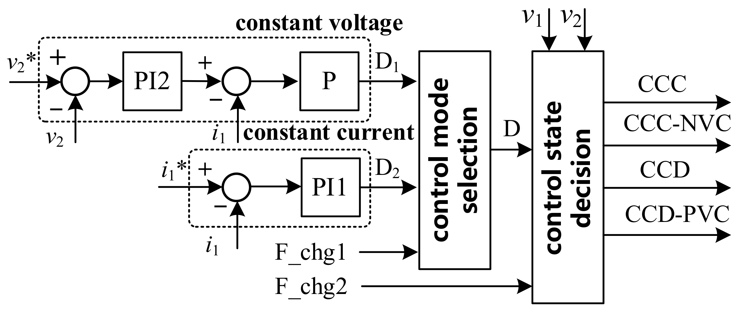
PI controls are used in practical applications, as shown in
Figure 7. In the control mode selection, when F_chg1 is 0, the constant voltage control is selected, and the battery voltage
v2 and reference
v2* are used in the PI2 controller to obtain current reference
iref. Next, the current
i1 and reference
iref are used in a P controller to obtain the duty ratio
D1; the final duty ratio is equal to
D1. When F_chg1 is 1, the constant current control is selected, and the current
i1 and reference
i1* are used in the PI1 controller to calculate the duty ratio
D2 directly; the final duty ratio is equal to
D2.
In the control state decision, when F_chg2 is 0, battery charging is selected. If
v2 <
v1, the converter operates in the CCC state; otherwise, it operates in the CCC-NVC state. When F_chg2 is 1, battery discharging is selected. If
v1 <
v2, the converter operates in the CCD state; otherwise, it operates in the CCD-PVC state. According to the analysis in
Section 3, the switches S
1, S
2, S
3, and S
4 are used in this order.
6. Experiment
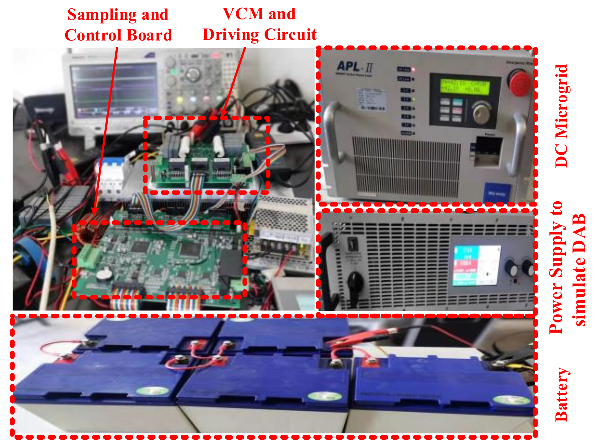
To further verify the principle and control strategy, a physical prototype was built, as shown in
Figure 12. An electronic load APL-II (Myway company) simulated a DC grid, and a bidirectional power PSB9750 (EA company) simulated the power supply. Moreover, five lead-acid battery cells (LCPA33-12) were used as an experimental battery. In the experiment, two THDP0200 (TEK company, ratio 100/1) voltage probes and one P5200A (TEK company, ratio 50/1) voltage probe measured voltages, and a current probe TCP0150 (TEK company) measured current.
6.1. Experiments during Charging Process
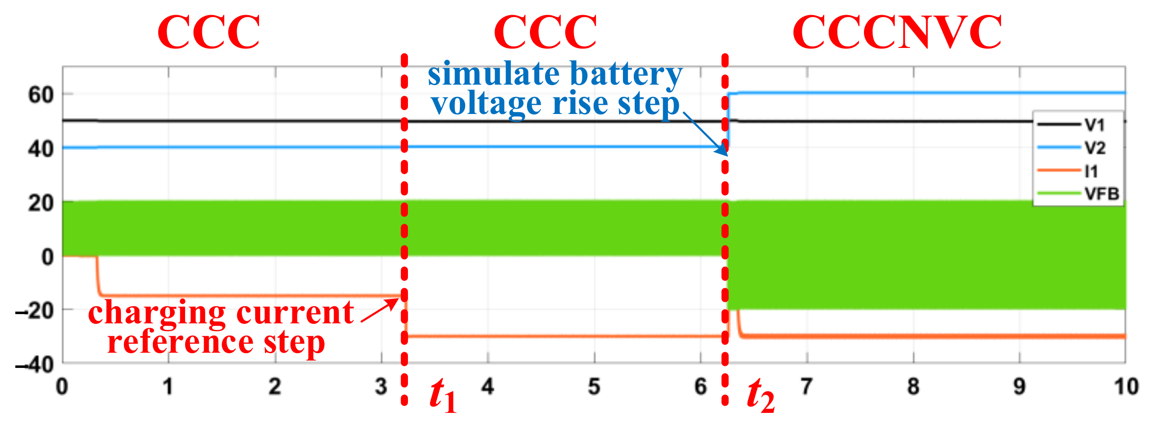
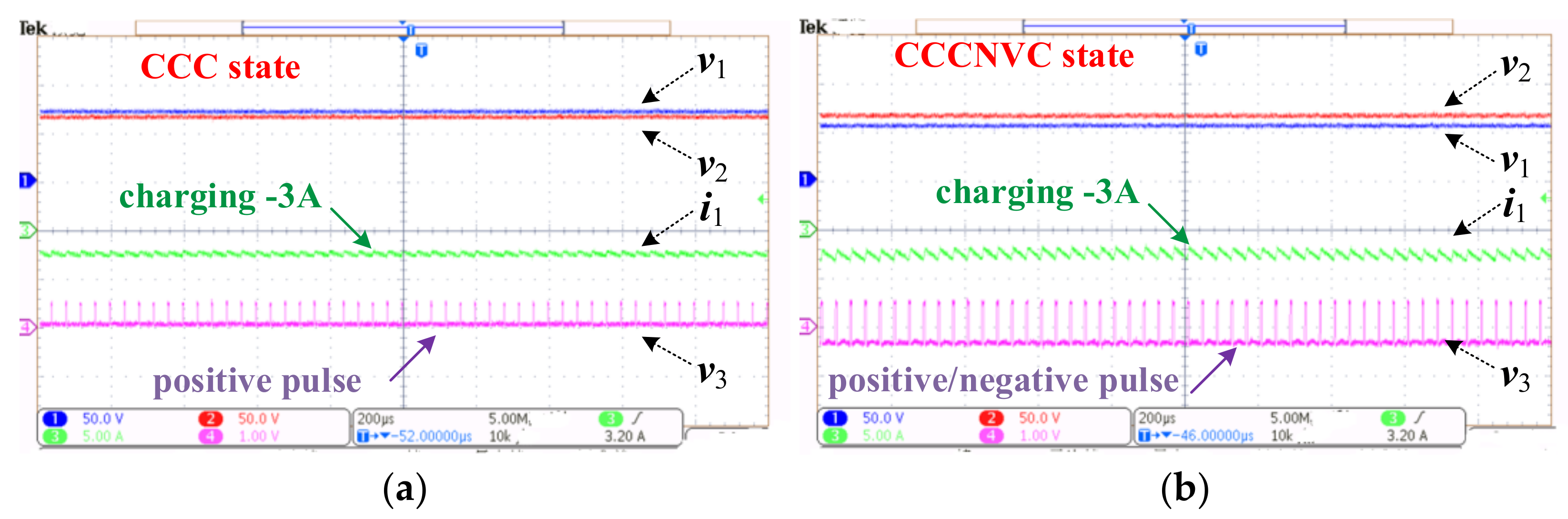
Figure 13 shows voltages and current waveforms during the charging process. As shown in
Figure 13a, when the battery voltage was lower than the DC grid voltage, the VC-PCS charged the battery with −3 A; it was operating in the CCC state, and the FB voltage was a positive pulse wave.
As shown in
Figure 13b, when the battery voltage was higher than the DC grid voltage, the VC-PCS charged the battery with −3 A; it was operating in the CCC-NVC state. The FB voltage was a negative or positive pulse wave, and the negative voltage was greater than the positive voltage, so a negative voltage was compensated.
The experimental results showed that whether the battery voltage was lower or higher than the DC grid voltage, the VC-PCS could charge the battery with the same currents; the waveforms were always consistent with the theoretical analysis.
6.2. Experiment during Discharging Process
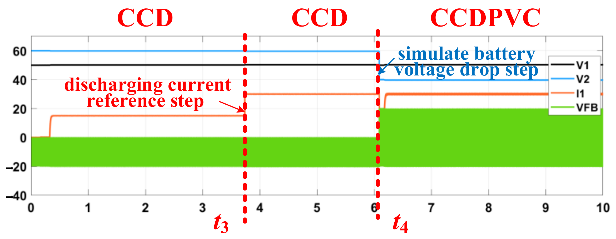
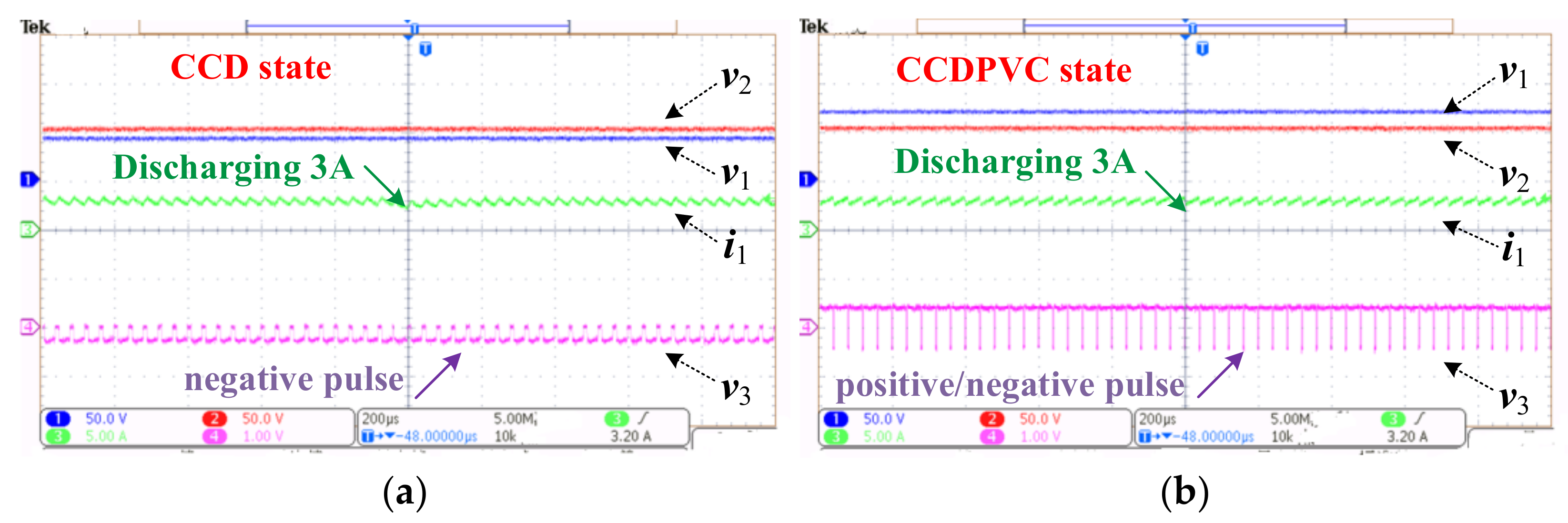
Figure 14 shows the voltages and current waveforms during the discharging process. As shown in
Figure 14a, when the battery voltage was higher than the DC grid voltage, the VC-PCS discharged the battery with 3 A; it was operating in the CCD state, and the FB voltage was a negative pulse wave.
As shown in
Figure 14b, when the battery voltage was lower than the DC grid voltage, the VC-PCS discharged the battery with 3 A; it was operating in the CCD-PVC state. The FB voltage was a positive or negative pulse wave, and the positive voltage was greater than the negative voltage, so a positive voltage was compensated.
The experimental results show that whether the battery voltage was higher or lower than the DC grid voltage, the VC-PCS could discharge the battery with the same currents; the waveforms were consistent with the theoretical analysis.
6.3. Experiment during State Transition Process
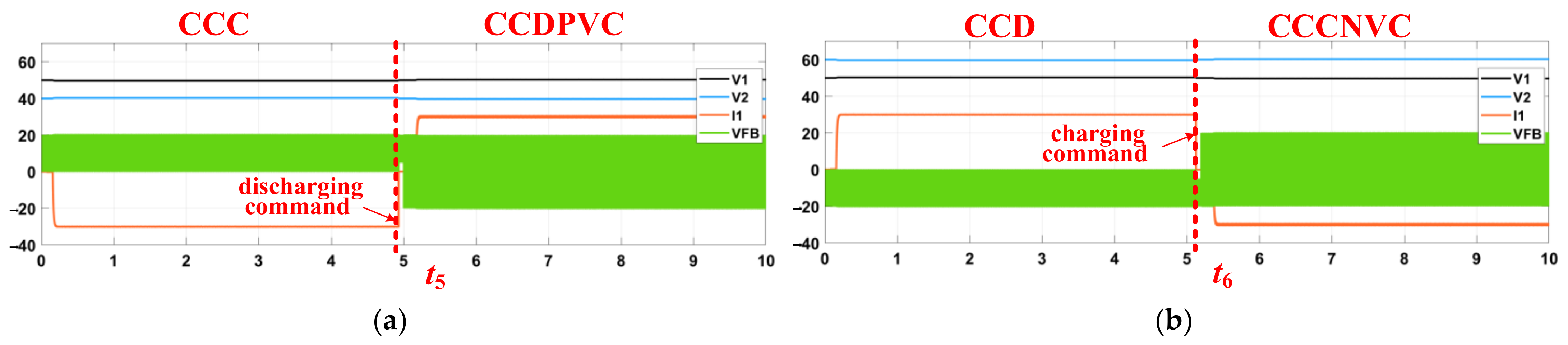
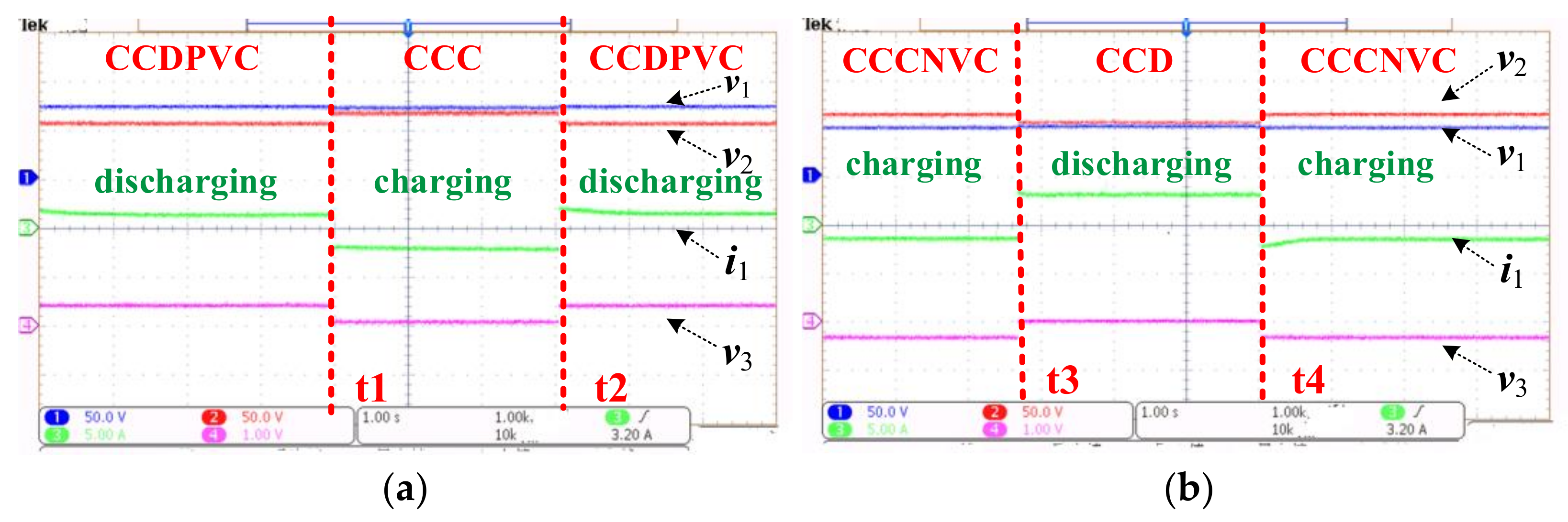
Figure 15a shows state transition waveforms when the battery voltage was lower than the DC grid voltage. At first, the VC-PCS discharged the battery with 3 A, and it operated in the CCD-PVC state. At time
t1, a charging battery command was set, the VC-PCS began to charge the battery with −3 A, and it operated in the CCC state. At time
t2, a discharging battery command was set again, the VC-PCS began to discharge the battery with 3 A, and it operated in the CCD-PVC state again.
Figure 15b shows state transition waveforms when the battery voltage was higher than the DC grid voltage. At first, the VC-PCS charged the battery with −3 A, and it operated in the CCC-NVC state. At time
t3, a discharging battery command was set, the VC-PCS began to discharge the battery with 3 A, and it operated in the CCD state. At time
t4, a charging battery command was set again, the VC-PCS began to charge the battery with −3 A, and it operated in the CCC-NVC state again.
This shows that whether the battery voltage was higher or lower than DC grid voltage, the VC-PCS could charge or discharge the battery arbitrarily; it could also realize a fast transition between charging and discharging states with good transient performance, and was always consistent with the simulation results.
7. Conclusions
Compared with traditional PCS, the proposed VC-PCS has lower-rated voltage and power, and is an alternative to power energy storage applications. Its theoretical analysis, simulation, and experimental verification are analyzed in this paper; it is a necessary and comprehensive improvement to previous research, especially with regard to physical verification. This paper shows that a VC-PCS can operate normally regardless of voltage variation and state transition, and that it is feasible in principle. In the future, we will conduct further research, including a technical economy analysis and an efficiency comparison, and will try to solve technical problems regarding practical applications.


