1. Introduction
At COP21 (Conference of Parties), the Paris Agreement was adopted as a new international framework for reducing greenhouse gas emissions after 2020. The Paris agreement has set a goal of achieving carbon neutrality by 2050. Renewable energies such as photovoltaics and wind power are expected to expand further to achieve carbon neutrality. In this context, there is growing interest in the use and development of GTCC plants, which are 40% more thermally efficient than state-of-the-art coal-fired power plants and can reduce carbon dioxide emissions to about 1/3 of those from coal-fired power plants when burning fossil fuels. A GTCC is a plant that combines a steam turbine operating in the Rankine cycle and a gas turbine operating in the Brayton cycle. The maximum steam temperature of the steam turbine must be maintained at approximately 620 °C due to the limited heat resistance of the materials used in the steam turbine. Therefore, to improve the thermal efficiency of the GTCC, it is necessary to increase the turbine inlet temperature and pressure ratio of the gas turbine exclusively.
Increasing the turbine inlet temperature and the pressure ratio of a gas turbine is necessary for improving the thermal efficiency of a GTCC. Therefore, let us first take a brief look at the history of industrial gas turbines. The world’s first industrial gas turbine was put into commercial operation for power generation in Neuchâtel, Switzerland, in 1939 [
1,
2]. This gas turbine was manufactured by BBC and had a rotational speed of 3000 rpm, a turbine inlet temperature of 550 °C, a thermal efficiency of 17.4%, and an output of 4000 kW. This period coincided with the successful development of the world’s first jet engine for aviation by Whittle and Hans Von Ohain [
3,
4]. Improvements in the thermal efficiency of industrial gas turbines did not follow the increasing thermal efficiency rate of larger and hotter steam turbines, as shown in
Figure 1 [
5], and industrial gas turbines were rarely used as baseload power generators at that time. The turbine inlet temperature of jet engines increased dramatically [
6], as shown in
Figure 2 [
7].
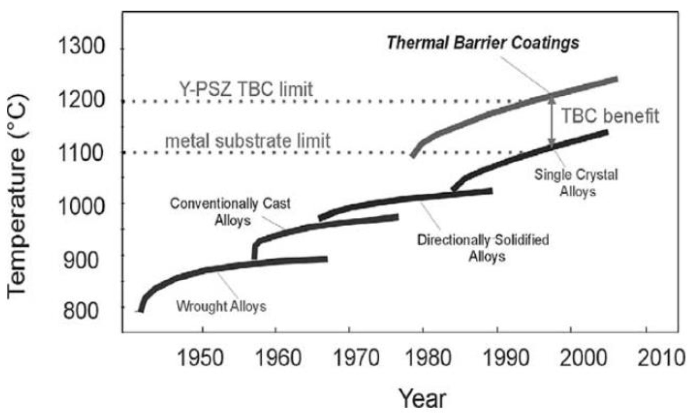
Technologies that enable this turbine inlet temperature increase include turbine blade cooling technology, material technology, and thermal barrier coating technology.
Figure 3 [
8] shows the progress in turbine blade materials and thermal barrier coating technologies. Materials with excellent creep strength and oxidation resistance have been developed by optimizing the alloy composition of super heat-resistant alloys used as turbine blade materials. The precision casting method for manufacturing turbine blades has been improved to eliminate grain boundaries toward conventional casting (CC), directionally solidified (DS), and single crystal (SC), and it is now possible to develop turbine blades with excellent creep strength and thermal fatigue resistance [
9]. SC has enabled the development of turbine blades with superior creep strength and thermal fatigue [
9,
10]. Among the three key technologies that support high-temperature gas turbines,
Figure 2 clearly shows that advances in turbine blade cooling technology have contributed the most to the increase in turbine inlet temperature.
In the late 1970s, when commercial jet engines were operating at turbine inlet temperature levels of about 1250 °C, large industrial gas turbines were developed at turbine inlet temperature levels of about 1150 °C [
11]. The combined cycle power plant at the Higashi Niigata Power Station of Tohoku Electric Power Company was the world’s first successful example of a large-scale GTCC. The gas turbine used in this GTCC was a 701D gas turbine, which is designed and manufactured by MHI. The turbine inlet temperature of the 701D gas turbine was 1154 °C [
12,
13]. The thermal efficiency of the GTCC using this gas turbine as the main engine was 44% (relative to the higher heating value or HHV), which was more than 10% higher than the thermal efficiency of the most advanced coal-fired thermal power generation systems at the time [
14]. Even today, utilizing LNG as a fuel reduces carbon dioxide emissions by about 20% compared to coal-fired power generation [
14]. The success of this highly efficient large-scale GTCC power generation facility was praised as an energy-saving technology that could cope with the oil crisis, which subsequently triggered a worldwide rush to build large-scale GTCCs.
Gas turbine manufacturers have focused on developing large industrial gas turbines with higher temperatures and pressures. The power demand led to the development of the 1350 °C-class F-type gas turbine, the 1500 °C-class G-type gas turbine, and the 1650 °C-class J-type gas turbine, which is now the most advanced model [
15]. The thermal efficiency of a GTCC with a 1650 °C-class J-type gas turbine as the main engine is 64% (LHV), and the carbon dioxide emissions are reduced to about 1/3 compared to coal-fired power generation [
16].
With the successful development of the 1650 °C J-type gas turbine, the technology level of turbine cooling vanes and blades for large industrial gas turbines has caught up with that of jet engines in terms of turbine inlet temperature level. Before discussing the development of turbine vanes and blades for industrial gas turbines, it is necessary to recognize the differences in characteristics between industrial gas turbines and aero jet engines. The most distinctive feature of industrial gas turbines is the diversity of fuels. In particular, small industrial gas turbines have this feature because they are sometimes used for cogeneration. The turbine blades of small industrial gas turbines are similar in size to those of aircraft jet engines, but their firing temperatures are far below those of large industrial gas turbines or aero-engines. Aero jet engines use only jet fuel, which is extremely difficult to misfire in combustion. The second feature is that industrial gas turbines have no weight limitations. This allows the cooling air extracted from the compressor exit to be cooled using a heat exchanger. In addition, steam or water, which has a higher specific heat than air, can be used as a coolant. The third difference is that there are many different cycles for industrial gas turbines. One of the many possible thermal cycles, GTCC, is already in practical use. Understanding these three major characteristics of industrial gas turbines is necessary to consider future trends in cooled turbine vanes and blades.
Carbon neutrality can be achieved by 2050 by developing GTCCs with improved high-temperature industrial gas turbines as the main engine. For this purpose, it is necessary to develop ultra-high-temperature gas turbines with excellent thermal efficiency aiming for zero carbon dioxide emissions either by CCS or the burning of carbon-neutral fuels. The key technology to realize such an ultra-high temperature gas turbine is the cooling technology of the turbine blades. In this review paper, as a preliminary step to discussing the future trends of heat transfer and cooling technology to gas turbines, the technological transition of turbine cooling technology for jet engines and for industrial gas turbines will be reviewed. Future trends in turbine blade cooling technology, which is an extension of the turbine cooling blade technology developed to date, will be discussed. In addition, numerous promising new cycles have been proposed with the intention of achieving zero carbon dioxide emissions but have not yet been commercially developed. Among these new cycles, I will select several cycles suitable for carbon neutrality and present the turbine blade cooling technology used in these cycles.
2. Contribution of Aviation Turbine Cooling Blades to Industrial Gas Turbine Cooling Blades
To understand the progress of cooled turbine vanes and blades for industrial gas turbines, it is first necessary to understand the progress of cooled blades for aero-engines, which operate on kerosene. This is because the cooling structure of the vanes and blades used in large industrial gas turbines has been developed based on the cooling structure used in these engines. Therefore, this chapter briefly reviews the history of turbine air-cooled vanes and blades used in aero-engines. Because the dimensions of an aero-engine are comparable to those of a small industrial gas turbine, the diffusion bonded blades used in the F-100 engines for military fighter aircraft are discussed. The diffusion bonded blades were the result of research conducted by ERDA, the DOE, and P&W for a 10 MW-class industrial gas turbine as a national project in the US. Therefore, these are described in this chapter.
The history of cooled turbine blades in aircraft jet engines can be traced back to the 1935 German study of air-cooled and water-cooled blades. Air-cooled blades were first used in the Junkers Jumo 004 jet engine with a turbine inlet temperature of 2000° R (838 °C). The hollow turbine blades were made of low-alloy heat-resistant steel with cooling air flowing inside the hollow turbine blades, as shown in
Figure 4 [
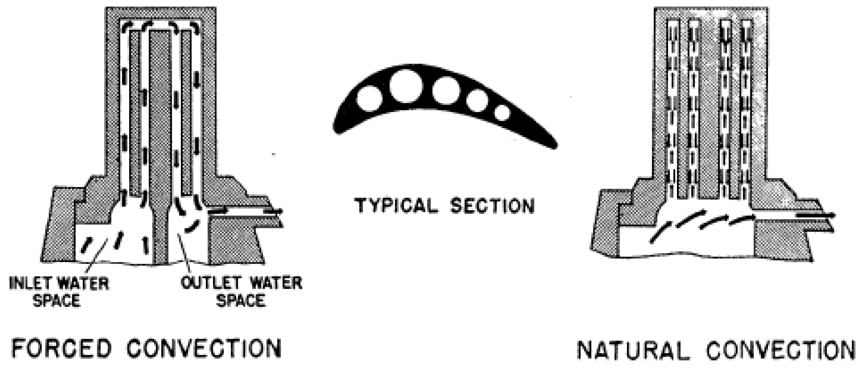
17]. In Germany, water-cooled turbine blades made of heat-resistant steel were also actively studied because of the difficulty in obtaining nickel, chromium, and other metals that make up heat-resistant alloys. As described in [
17], Schmidt used the water-cooled turbine blade shown in
Figure 5 and successfully operated a turbine with a turbine inlet temperature of 2700 °R (1227 °C).
Schmidt’s single-stage water-cooled turbine blades are cooled by the thermosiphon principle. Following the success of this experiment, a water-cooled four-stage turbine, shown in
Figure 6, named the rotating boiler, was designed [
18]. Steam is generated by water-cooling the inside of the turbine blades of a gas turbine consisting of a four-stage turbine with a turbine inlet temperature of 2190 °F (about 1200 °C), using the structure shown in
Figure 6. The plant used steam to drive the steam turbine. Attempts were made to develop a high-performance plant using such inexpensive heat-resistant steel, but the turbine cooling blades could not withstand prolonged use, and water-cooled turbine blades did not enter commercial production. It was not until the 1960s that full-scale air-cooled turbine blades were put to practical use in aero-engines.
The world’s first high-pressure turbine with cooled first-stage vanes and blades were the Tyne and Conway engines, commercial jet engines that Rolls-Royce began operating in 1961. In the Spey engine, in which the turbine inlet temperature and pressure ratio were further increased, cooled turbines were used for the stationary vanes and rotating blades in the first stage, as well as for the rotating blades in the second stage.
Figure 7 shows the cooling structure of the first-stage blades used in the Spey engine [
19]. Cooling air is supplied from the inner and outer shroud sides of the turbine vanes through inserts to cool the inner surfaces of the turbine vane leading edges, then flows between the inserts and the vanes to cool the turbine vane inner surfaces, and finally discharges into the main stream through holes on the pressure side near the turbine trailing edge. This cooling configuration still is the basic cooling structure of today’s state-of-the-art high-pressure turbine first-stage stationary vanes. The turbine first-stage rotor blades were forged and cooled by air flowing through a cooling passage that opens from the base of the blade to the tip, as shown in
Figure 8.
Since Rolls-Royce adopted air-cooled turbines for its commercial jet engines, jet engines have been developed with successively higher turbine inlet temperatures, pressure ratios, and bypass ratios in order to increase thrust and decrease fuel consumption rates. Rolls-Royce then produced the RB 211 and Trent engines, which were developed as high-bypass turbofan engines. Refs [
20,
21] shows the evolution of blade materials and cooling structures employed in turbine rotor blades in the Trent and RB 211 engine. Early jet engines barely lasted more than 10 h for high-temperature components, but today’s civilian engines can last 10,000 h, and high-performance military engines can keep their turbine blades for several hundred hours [
6].
There is no published information on the detailed cooling structures of the turbine vanes and blades used in modern engines with turbine inlet temperatures in the 1600 °C class. However, fundamental cooling structures can be seen in the results of the E
3 engine (Energy Efficient Engine) development research conducted as a joint NASA-GE, NASA-P&W research project [
22,
23]. This E
3 engine was the prototype for the CF6 or JT9D engines used in the Boeing 747.
The cooling structures of the first-stage vanes and blades of GE’s CF6-80C2 engine are shown in
Figure 9 and
Figure 10 [
24]. The high-pressure turbine first-stage stationary vanes have inner surface impingement cooling with two inserts, i.e., one in the front and one in the back of the airfoil. The E
3 engine uses showerhead cooling for the vane leading edge, and circular hole film cooling for the suction and pressure surfaces of the vane. Slot cooling is applied to the trailing edge of the turbine vanes, and cooling air is blown out of the pressure side near the trailing edge of the vanes to provide film cooling of the trailing edge. This structure is used to reduce aerodynamic losses by making the trailing edge as thin as possible. The cooling air cools the shroud section by impingement cooling and by film cooling holes with a diffused film cooling hole. The high-pressure turbine first-stage rotor blades are precision cast with ribbed serpentine channels, as shown in
Figure 10. The leading edges of the turbine blades are cooled by showerhead cooling, while the suction and pressure sides of the blades are cooled by circular film cooling holes. The diameter of the film cooling holes is about 0.5 mm.
The cooling structure of the CF6 engine’s HPT first-stage vanes and blades is considered the same as the HPT of today’s state-of-the-art jet engines. However, the latest technological development in each field is used to cope with higher temperatures. For turbine blade materials, super heat-resistant alloys with superior creep strength or oxidation resistance are used. In precision casting technology, turbine blades manufactured using casting methods with superior creep strength and oxidation resistance are used, from CC to DS and SC. Thermal-Barrier Coatings (TBC) have also been researched and developed for the E3 engine, and yttria-stabilized zirconia (YSZ) is the material most commonly used. Currently, high-performance TBCs with a lower thermal conductivity than that of YSZ are being researched and developed for use in actual engines. Turbine blade cooling technology has also advanced far beyond the time of the E3 engine. For the inner surface cooling of turbine blades, higher performance cooling structures have been developed. For film cooling, a higher performance film cooling method, represented by shaped film cooling holes, has been established.
The combustor of an aviation gas turbine is shortened in size compared to that of an industrial gas turbine to reduce weight. Diffusion combustion with liquid fuel takes place in the combustor. For this reason, cooling structures have been studied to effectively cool the combustor wall with low pressure loss and a small amount of cooling air. Lamiloy
® is a double-wall cooling structure developed for application in the combustor walls of aviation gas turbines. The cooling configuration of Lamilloy
® is shown in
Figure 11 [
25]. It consists of an outer wall, an inner wall (combustion side), and a structure with fins that promote heat transfer between them. The inner wall and fin structures are fabricated from a single metal plate by photo-etching, while the outer wall is bonded to the fin surface by diffusion bonding.
As the name suggests, CastCool
® is a high-pressure turbine first-stage blade manufactured by precision casting Lamilloy’s cooling structure. The fabricated CastCool
® turbine first-stage rotor blade is shown in
Figure 12 [
26,
27]. In the cooling configuration of the CastCool
® turbine blade, the relative positions of the impingement cooling and film cooling holes can be manufactured exactly as the designers intended with low deviations.
Figure 13 shows an example of the measured heat transfer coefficient distribution on the inner surface of a cavity with impingement cooling used in CastCool
® [
28]. This cooling structure combines two cooling methods: both the heat transfer coefficient of impingement cooling and the blowing ratio of film cooling can be controlled to optimize the film cooling effectiveness. This cooling method is able to achieve a uniform metal temperature across the entire turbine blade surface with a minimum amount of cooling air.
The High Temperature Turbine Technology (HTTT) Program is a US national project aimed at increasing the temperature of industrial gas turbines. Within this program, the Energy Research and Development Administration (ERDA) sponsored a study on the creation of first-stage turbine stationary vanes and rotor blades fabricated by photo-etching and diffusion bonding. The structure of the turbine first-stage stationary vane and rotor blade developed by ERDA is shown in
Figure 14 and
Figure 15 [
29], respectively. The first stage turbine vane was fabricated by forming a fine cooling structure on a thin plate of heat-resistant super alloy by photo-etching, overlapping the wafers in the radial direction, and integrating them by diffusion bonding. The fabrication method of the turbine first-stage rotor blade is the same as that of the first-stage vane. However, the orientation of the diffusion bonding surface is in the direction in which centrifugal force does not act, i.e., the axial direction. Within the same HTTT project, a turbine cooling blade study called “Shell/Spar” was conducted as EPRI’s R&D project for high temperature industrial gas turbines. The structure of the Shell/Spar first-stage rotor blade is shown in
Figure 16 [
30].
Although the cooling blade produced by photo-etching and diffusion bonding described above has excellent cooling performance, it has not been put widely into practical use due to its high cost. The only HPT first-stage blade produced using the method described here was put to practical use in the F100 fighter engine. The HPT first-stage blade of the F100 fighter engine is shown in
Figure 17 [
31].
3. Development of Cooled Turbine Blades used in Large Industrial Gas Turbines up to the Present Day
This section describes the evolution of cooled turbine blades and vanes used in large industrial gas turbines. The manufacturers of large industrial gas turbines include General Electric (GE), Siemens, Brown Boveri & Company (BBC) (which later became ABB, Alstom and then Ansaldo), Westinghouse (WH), and Mitsubishi Heavy Industries (MHI).
GE uses the air from the compressor discharge directly to cool the turbine rotor blades. However, WH cools the turbine rotor blades by bleeding the air from the compressor discharge outside the casing, cooling it, and then supplying it back to the rotating parts of the gas turbine. Thus, although the handling of coolant differs slightly between gas turbine manufacturers, the cooling methods of the turbine blades relative to the turbine inlet temperature are almost the same. Therefore, this paper will focus on the industrial gas turbine manufactured by WH-MHI, for which all of the cooling structures for the turbine vanes and blades and the corresponding turbine inlet temperature have been published.
The development of large industrial gas turbines, mainly for power generation, slowed down at that time when steam turbines were becoming larger and more powerful, as mentioned above. However, in the late 1960s, large industrial gas turbines with a TIT of 900 °C began to be developed. Industrial gas turbines with a TIT of 1000 °C were developed in the 1970s. However, GTCC using 1000 °C-class industrial gas turbines could not significantly exceed the thermal efficiency of the most advanced steam turbines at the time. The development of high-temperature industrial gas turbines with turbine inlet temperatures exceeding 1000 °C began around the same time that wide-body aircraft, for example the Boeing 747, were being developed and 1250 °C-class turbofan engines were installed in that aircraft. The research results of aero-gas turbines led to industrial gas turbines with higher temperatures, and WH developed the 1150 °C-class D-type gas turbine. Based on the 60-Hz Type 501D gas turbine designed by WH, MHI developed the 50-Hz Type 701D gas turbine. The GTCC using the 701D gas turbine was the Tohoku Electric Power Company’s Higashi Niigata Power Station, the world’s first large-scale combined cycle power plant [
14]. The thermal efficiency was 44% (HHV), about 10% higher than the thermal efficiency of the most advanced coal-fired power plants at that time. The GTCC was the catalyst for higher temperatures in industrial gas turbines and the subsequent worldwide rush to build natural gas-fired combined cycle power plants [
32]. All gas turbine manufacturers developed new, higher-performance models. As a result, WH-MHI developed a 1350 °C-class F-type gas turbine and a 1500 °C-class G-type gas turbine.
The cooling structure of the first-stage nozzles and rotor blades used in the industrial gas turbines produced by WH-MHI is shown in
Figure 18 as a function of turbine inlet temperature [
33]. Only the first stage vanes are cooled in the Type 501A gas turbine with a TIT of 907 °C. Only the inner surface of the leading edge is impingement cooled. The TIT of the 501B gas turbine is 1021 °C. The cooling structure of the single-stage vane of this engine consists of the impingement jet cooling of the leading edge and the inner surface of the suction surface, and convection cooling of the pressure surface inside the vane by air from the leading edge. All the cooling air discharged into the main stream through slots in the trailing edge. Radial cooling holes were adopted as the cooling structure for the first-stage rotor blades. Radial cooling holes made using precision casting with silicon tubes or electrical discharge machining on solid airfoils allow air to flow from the root to the tip of the blade for cooling. The TIT of the 501D gas turbine is 1154 °C. Here, film cooling was used for the first time for the first stage stationary vanes; the original first stage vanes developed by WH were cooled by impingement cooling with two inserts. The air was then blown into the main stream through inclined circular film holes on the suction and pressure surfaces of the turbine vanes. Pin-fin cooling was employed on the trailing edges of the turbine vanes [
11]. The first-stage blades used radial cooling holes, as in the Type 501B gas turbine. The first-stage vanes and blades of the D-type gas turbine were improved by MHI for the 1250 °C-class DA-type gas turbine [
34], with three-cavity first stage vanes and showerhead cooling on the leading edge of the vanes, as shown in
Figure 19. The first-stage rotor blades employed a double radial cooling hole structure arranged along the blade surface. The MF 111 gas turbine is a 13 MW gas turbine originally developed by MHI with a turbine inlet temperature of 1250 °C [
35]. The first-stage nozzles employed double impingement cooling with film cooling, and pin-fin cooling at the trailing edge. The first-stage rotor blade used a ribbed serpentine flow path, and pin fin cooling was used on the trailing edge.
In response to the electric power industry’s demand for energy conservation and reduction of carbon dioxide emissions to prevent global warming, WH-MHI developed the 1350 °C-class F-type gas turbine [
36,
37]. Later, the 1500 °C-class G-type gas turbine was conceived, which is a higher temperature and more efficient gas turbine than the F-type gas turbine [
38,
39]. Additionally, the 1600 °C-class J-type gas turbine was designed and developed by MHI. Today, a 1650 °C-class JAC gas turbine is available in which the combustor walls of the 1600 °C-class J gas turbine, which had been steam-cooled, are now air-cooled, further raising the turbine inlet temperature by 50 °C [
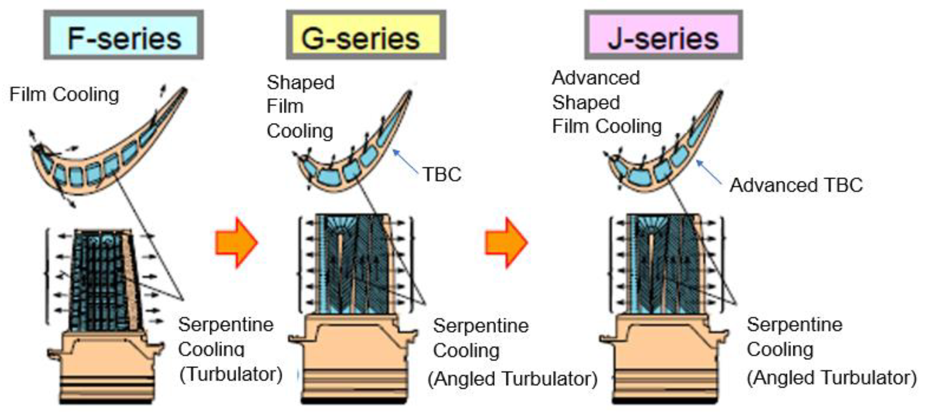
40]. The transition of the cooling structure of the first-stage stationary vane and the first-stage rotor blade from the F-type to the J-type is shown in
Figure 20 and
Figure 21, respectively [
41,
42]. The F-type gas turbine uses inclined circular film cooling holes, while the development of air-cooled turbine vanes and blades that can withstand ultra-high temperatures has been achieved by the G-type gas turbine that uses shaped-film cooling holes; the film hole outlet shape expanded only in the span-wise direction. Additionally, high-performance laid-back-shaped-film cooling holes are adopted in J-type gas turbines. Thus, the development of air-cooled turbine vanes and blades that can withstand ultra-high temperatures has been achieved through the advancement of turbine blade cooling technology and the development of turbine blade materials and TBCs [
43].
The turbine inlet temperature of a gas turbine can theoretically be increased to the stoichiometric temperature of the fuel used. Increasing the turbine inlet temperature and pressure ratio to improve the thermal efficiency of the gas turbine will result in a corresponding increase in the amount of cooling air required to cool the high-temperature components. Although the allowable temperatures of heat-resistant alloys used for the high-temperature components have tended to increase with the development of super heat-resistant alloys with superior alloy compositions, they could not keep pace with the increasing speed of the elevation of turbine inlet temperatures. The dimensions of the first-stage turbine stationary vanes and rotor blades of industrial gas turbines are about four times larger than those of aero-engines. The technology to manufacture turbine blades of such large dimensions in monocrystalline form is a testament to superior technology, but large vanes and blades made of SC are exceedingly costly. For thermal barrier coatings, materials with lower thermal conductivity and superior oxidation resistance and bonding properties of bond coat layers are being researched and developed, but the pace of development is similar to that of super heat-resistant alloys. If the amount of air for cooling the high-temperature components is increased parallel to that of the turbine inlet temperature, the expected improvement in thermal efficiency will not be drowned out [
44]. A possible solution is to cool the high-temperature components using a coolant other than the air extracted from the compressor.
It was already mentioned that in the past, water-cooled gas turbines were studied in Germany. Water is a suitable coolant for cooling turbine blades because of its excellent heat transfer performance and large heat capacity due to its high specific heat. However, although the cooling performance of water is high, the selection of materials that reduce the thermal stress generated by the water and the method of recovering the water from the turbine blades were problems. In the 1980s, a national project for integrated coal gasification combined cycle (IGCC) turbines started in the United States. IGCC aims to use coal, the most abundant fuel reserve, more efficiently for power generation. For gas turbines used in IGCC, it is necessary to develop high-temperature components that can handle corrosive components, such as sulfur, in coal gasification and coal ash deposits. When water is used to cool turbine blades, the high heat transfer coefficient of water keeps the metal temperature of the turbine blades below that at which corrosion occurs. No water is sprayed into the main stream by film cooling, the main-stream temperature is not reduced, and aerodynamic losses are also reduced, which has the great advantage of increasing the thermal efficiency and power output of the IGCC. The HTTT program to develop coal gasification gas turbines was implemented in the U.S. in the 1980s by gas turbine manufacturers, ERDA, EPRI, and the DOE. This section describes the research and development of water-cooled gas turbines conducted by GE in that program [
45,
46]. A turbine blade inlet temperature of 1430 °C and a pressure ratio of 23 were set for the coal gasification gas turbine. The most difficult design challenge was the cooling structure for the stationary vanes and rotor blades of the turbine’s first stage. The cooling structures adopted for the turbine first-stage stationary vane after various studies are shown in
Figure 22. The upper limit of the turbine blade metal temperature was set at 538 °C to prevent corrosion of the turbine blade material and adhesion of coal ash. This metal temperature could be achieved with a simple cooling structure due to the excellent cooling performance of water. However, if the entirety of the cooled turbine blades were made of super heat-resistant alloys with low thermal conductivity, high temperature differences in the blade thickness direction would occur, and thermal fatigue life requirements could not be satisfied. Therefore, a copper alloy with excellent thermal conductivity was selected as the base metal for the turbine blades. The turbine blade surfaces in contact with the main-stream gas are bonded to a thin plate of Inconel 617 material. The Spar is also placed to support the first stage stationary vane against the bending force of the main-stream gas. The cooling structure of the turbine first-stage rotor blade is shown in
Figure 23 [
46]. The method used for the cooling configuration of the first-stage rotor blade is the same as that used for the first-stage stationary vane, and is designed to reduce thermal stress. The water used to cool the first-stage rotor blade is pressurized to prevent boiling in the turbine rotor blade. After cooling the turbine blades internally, the cooling water is blown out from the blade tips. As shown in
Figure 24, cooling water blown from the tip section of the turbine rotor blades is captured by the annular stationary shrouds. The water-cooled gas turbine planned in this program had four stages, with water-cooled turbine rotor blades for the first through third stages. The four-stage turbine is uncooled.
The developed turbine blades were incorporated into a large industrial gas turbine and tested as part of a coal gasification power plant. The first-stage rotor blades were improved by solving problems that would not occur with air-cooled turbine rotor blades, such as erosion caused by water flow through the high-thermal-conductivity copper alloy and blade vibration caused by boiling.
Steam cooling of the turbine blades was also considered as a backup cooling method in the HTTT program. Using steam as a coolant for the turbine blades is easy for a combined cycle plant. Steam is extracted from the steam turbine, which constitutes the bottoming of the combined cycle, and the steam is used to cool the high-temperature components. From the steam turbine’s perspective, the high-temperature components are considered steam heaters, and the heated steam is returned to the steam turbine without being released into the main stream. Similar to water cooling, the cooling circuit employed in steam-cooled gas turbines is a method that constitutes a closed cooling system as described above. The impact of air-based open-circuit, steam-based open-circuit, and steam-based closed-circuit turbine cooling systems on the combined cycle performance was studied in [
47,
48]. Closed-circuit turbine cooling systems with steam have the best performance. The Advanced Turbine Systems (ATS) program was conducted in the United States to develop and study steam-cooled gas turbines [
49].
GE has successfully developed a steam-cooled gas turbine, the Model H, based on the results of the ATS program. The specifications of the steam-cooled gas turbine, a 50 Hz model 9 H, are a turbine blade inlet temperature of 1430 °C, a pressure ratio of 23, a combined output of 480 MW, and a combined thermal efficiency of 60% (LHV) [
50]. The steam cooling circuit used in the H-type gas turbine is shown in
Figure 25. The first and second-stage turbine vanes and rotor blades are steam cooled in a closed circuit, the third-stage turbine vane and rotor blade are air-cooled, and the fourth-stage turbine vane and blade are uncooled. The turbine blades for the first stage are made of single crystals Rune N5. The steam-cooled structure of the vanes and blades has not been published, but an SC precision casting of the first stage stationary vane from a GE paper is shown in
Figure 26. The figure shows that steam cooling has superior cooling performance, including a lower temperature rise than air cooling [
51]. A combined cycle with a steam-cooled gas turbine as the main engine outperforms a combined cycle with an air-cooled gas turbine in terms of thermal efficiency and power output. Since steam is used as the coolant for the gas turbine, it takes time for the closed circuit to operate without problems and for the combined plant to reach rated operation. In other words, the ability of the gas turbine to start up rapidly is reduced. It is estimated that it is difficult to increase the turbine inlet temperature and pressure ratio of a steam-cooled gas turbine as long as a closed-circuit system is used. Considering the thermal stress on the first stage rotor blade, which is internally cooled by steam, it is thought that the stress limit has been reached. The SC first-stage turbine rotor blades are made of Rene 60, which is resistant to thermal fatigue.
After developing and operating a steam-cooled gas turbine, GE developed an HA-type air-cooled gas turbine with a first-stage blade entry temperature of 1593 °C and a total GTCC efficiency of 61% or higher (LHV) [
52]. The GE HA gas turbine has the same turbine inlet temperature as the MHI JAC gas turbine, so it is estimated that the turbine vanes and blades cooling structure uses similar cooling methods.
4. New Trends in Turbine Blade Cooling Technologies for Large Industrial Gas Turbines
In the coming carbon-neutral era, gas turbine-based power generation plants will continue to play an important role due to their high thermal efficiency and flexibility of fuels. One way to reduce carbon dioxide emissions to zero plant is to employ Carbon dioxide Capture and Storage (CCS) [
53]. The amount of carbon dioxide that needs to be captured is only 1/3 that of coal-fired power. Because industrial gas turbines have the advantage of being highly flexible in terms of fuel, there are ways to operate gas turbines using hydrogen or ammonia as fuel, which do not produce carbon dioxide. Either method can achieve carbon neutrality, but the real thermal efficiency is significantly lower than that of the natural gas-fired combined cycle power plant of the latest generation. In case CCS is used, the actual thermal efficiency of the combined cycle is reduced by 10% to 15% when the energy used for CCS is considered. On the other hand, when hydrogen or ammonia is used as fuel, the cost of generating these fuels is higher than that of natural gas, which increases the cost of power generation for these plants. Whichever method is adopted, the thermal efficiency of the combined cycle plant will need to be about 10% higher than that of the current combined plant to maintain a power generation facility with a thermal efficiency equal to or higher than that of the latest natural gas-fired combined cycle plant in the future. The maximum temperature at which steam turbines will operate is expected to increase in the future. For now, it is assumed to remain at the current level of a maximum temperature of 620 °C. The turbine inlet temperature and pressure ratio of the gas turbine to be used in the future combined cycle plant will be 2000 °C and 30, respectively. The target combined thermal efficiency is 70% (LHV).
Turbine cooling technology alone cannot develop a method to ensure the integrity of turbine stationary vanes and rotor blades used in large industrial gas turbines with these thermodynamic parameters. Turbine blade materials with improved heat resistance temperatures, ceramic-based composites with excellent heat resistance and fracture toughness, and thermal barrier coatings with low heat conduction and strong bonding properties need to be developed. A TIT of 2000 °C can only be achieved by integrating these advances in high-temperature technology and balancing the individual technologies to share the increase in gas temperature.
In the following, the characteristics of a large industrial gas turbine in a carbon-neutral era, and then cycle considerations, fuel, turbine blade materials, thermal barrier coatings, and turbine cooling vanes and blades to achieve the development of an industrial gas turbine in a carbon-neutral era will be discussed.
4.1. Cycle and Fuel
Until now, various types of thermal cycles have been considered for gas turbine-based power generation plants, with the goal of achieving the highest thermal efficiency [
54,
55]. As these studies show, complex cycles are needed to increase thermal efficiency. Closed-circuit cooling systems, especially those that use a coolant such as water or steam to cool hot parts, are very effective in improving thermal efficiency and power output because they do not lower the main stream temperature of the turbine. However, the operation of a closed-circuit cooling system requires time for the components of the combined plant to be heated through, and the turbine inlet temperature cannot be higher than 1500 °C because the vanes and rotor blades are internally cooled and, therefore, subject to significant thermal stress.
A review of the operational status of thermal systems with gas turbines as the main engine developed to date shows that the combined cycle, consisting of a gas turbine and a steam turbine with cooling of the hot parts with compressor discharge air, is the most suitable for carbon neutrality. Future combined cycle power generation systems are required to have fast startup times, as well as response times to sudden load changes, and high thermal efficiency during partial load operation. In other words, a system that maintains a high thermal efficiency in partial load operation is more important than a system that operates at the highest thermal efficiency in rated operation, which is the characteristic of current combined power generation facilities [
56].
The major components that make up a gas turbine are not significantly different [
57,
58,
59,
60,
61] between a gas turbine that uses hydrogen or ammonia as fuel and the natural gas-fired industrial gas turbines currently in operation, with the exception of the combustor. In the case of a 100% hydrogen-fired gas turbine, the amount of radiative heat transfer from superheated steam in the main stream is expected to increase. A low emissivity thermal barrier coating should be applied to the turbine first-stage stationary vanes and rotor blades.
In the future, when natural energy, such as solar or wind power, is used to electrolyze water to produce large amounts of hydrogen and oxygen, hydrogen–oxygen combustion gas turbines can be developed. Hydrogen–oxygen combustion gas turbines have gas turbine in the name, but the working fluid is superheated steam, i.e., they are very high-temperature, high-pressure steam turbines. The turbine inlet temperature of hydrogen–oxygen combustion gas turbine currently under consideration is 1600 °C and the pressure ratio is 200–300 [
62,
63]. The dimensions of the first-stage stationary vane and rotor blade are expected to be similar to those of a jet engine. Therefore, the cooling method used for the first-stage blade of the hydrogen–oxygen combustion gas turbine should be similar to the first-stage turbine rotor blade of a 2000 °C-class industrial gas turbine with a double-wall or triple-wall cooling structure, as described below. However, because the pressure (and, as a thermodynamic consequence, the temperature) at which the first-stage vanes and blades operate is very high, the thermal load on them is high, and it is necessary to employ full-coverage film cooling with dense film cooling holes or transpiration cooling to cope with them.
If hydrogen and oxygen are produced using renewable energy, it is expected that only hydrogen will be used as fuel in the process. Here, there would be a surplus of oxygen, which could be used in a new thermal cycle. This new cycle is the Oxy-Fuel cycle [
64]. A closed Oxy-Fuel-cycle would require the exhaust gas to be cooled with water from the bottoming steam turbine using an enormous heat exchanger. However, since the exhaust gas is mostly carbon dioxide, carbon dioxide gas, which is roughly equal to the amount of fuel and oxygen, can be easily captured from the system at atmospheric pressure. Carbon dioxide gas extracted from the compressor can be expected to provide superior cooling performance compared to air cooling for cooling high-temperature components. The main stream is a mixed flow of carbon dioxide gas and superheated steam, which provides intense radiation heat transfer to the hot parts facing the main stream. However, since the coolant medium is carbon dioxide gas, the carbon dioxide gas used for cooling may absorb radiant energy in the areas covered by the film cooling. In any case, the integrity of the turbine cooling vane and blade should be evaluated considering the emissivity of the thermal barrier coating.
4.2. Super Alloys and CMC
In the beginning, the development of super heat-resistant alloys was based on empirical knowledge and experiments. Subsequently, as the number of elements used in heat-resistant alloys increased, so-called alloy design methods were used to estimate the effects of element combinations and content on metal properties through theoretical analysis and statistical methods. This alloy design method has led to the successful development of super heat-resistant alloys with dramatically improved maximum operating temperatures. In the recently developed sixth generation TMS-238, by increasing the addition of Cr, a similar oxidation resistance to that of the second generation alloys with a substantially increased creep rupture life was successfully obtained, as shown in
Figure 27 [
65]. In recent years, research has been conducted on new alloys combining the addition of Ir, which has a microstructure stabilizing effect similar to that of Ru, and an alloy that reaches a service temperature (stress 137 MPa, 1000 h creep rupture) of 1136 °C has been successfully developed [
66].
Ceramic Matrix Composites or CMCs consist of fibers embedded in a ceramic matrix. Fiber reinforcement is used to improve the fracture toughness. In stress–strain behavior, monolithic ceramics are characterized by a steep linear rise followed by brittle fracture, while CMCs exhibit a quasi-plastic curve. Compared to monolithic ceramics, CMCs exhibit more damage-resistant material behavior and can be used under high thermal-mechanical loads, such as in high-temperature stationary sections of gas turbines [
67].
The density of CMCs is about 1/3 of that of super heat-resistant alloys. This characteristic of CMCs has accelerated research into the application of CMCs to hot parts for aero-engines, and GE is commercializing a shroud made of CMCs for the high-pressure turbine rotor blades of the CFM LEAP engine. In addition, GE plans to apply CMC stationary hot parts such as combustors and high-pressure turbine first-stage vanes to its latest engines, including the LEAP and GE9X engines [
68,
69]. In large industrial gas turbines, GE has manufactured the combustor and the shrouds for turbine rotor blades of a 1400 °C-class FA gas turbine using CMCs and has even mounted and tested the shrouds on an actual engine [
70].
4.3. Thermal Barrier Coating (TBC) and ODS Coating
TBCs are applied to all turbine cooling vanes and blades of high-efficiency gas turbines that operate at high temperatures [
71]. Porous yttria-stabilized zirconia (YSZ), which has a low thermal conductivity, a similar coefficient of thermal expansion to that of the base material, and a small modulus of elasticity, is widely used for the topcoat. Since TBCs for aerospace applications are required to have durability against thermal cycles of rapid startup and load fluctuation, the electron beam Physical Vapor Deposit (PVD) method is used as a manufacturing method for TBCs. Gas turbines for power generation are used in the rated operation, and turbine stationary vanes and rotor blades are about four times larger than those for aviation, so plasma spraying is exclusively chosen as the construction method [
72]. Recently, thermal barrier materials with lower thermal conductivity properties than conventional YSZ have been researched and developed to increase the effectiveness of the TBC [
73]. The bond coat must have a dense metallurgical structure for adjusting and bonding the thermal expansion difference between the topcoat and the base material and for the role of shielding the base material from oxygen. MCrAlY (where M is Ni, Co, or NiCo) has been used as a bond coat material. The TBC for industrial gas turbines in a carbon-neutral era should be based on the construction of TBCs currently used in turbine cooling blades for aviation, as they need to be durable against load fluctuations. The ceramic coating layer of the topcoat and the metal layer of the bond coat cannot structurally support the load in the same manner as the base metal. Therefore, research has been conducted to develop high-temperature protective coatings that bear structural stress on super heat-resistant alloy base materials using additive manufacturing (AM) technology with oxide dispersion strengthening (ODS) powder [
74]. Undercoating with ODS is beneficial as a bond coat for vanes and blades in a thin-walled double-wall cooled turbine.
4.4. Cooled Vanes and Blades
The cooling structure of turbine stationary vanes and rotor blades used in industrial gas turbines in a carbon-neutral era will be discussed. Renewable energy sources such as solar and wind power are expected to account for about 60% of the electricity generated worldwide in the future. GTCCs and nuclear power will provide 40% of the electricity. With this generation configuration, it is necessary to even out the weather effects using GTCC because nuclear plants cannot cycle quickly enough. Therefore, industrial gas turbines, which are the main engines of GTCCs, are required to be able to follow load fluctuations, including rapid starts. Selecting a simple equipment configuration from the viewpoint of meeting the thermal fatigue life of hot parts as a combined-plant power generation system that can operate following load variations is of the utmost importance. Additionally, a cycle performance-insensitive design that maintains good thermal efficiency even in partial-load operation is needed, instead of achieving maximum efficiency at the rated point. As mentioned above, the thermal efficiency of a combined power plant should be about 10% higher than the thermal efficiency of today’s state-of-the-art combined power plants. The turbine inlet temperature and pressure ratio of an industrial gas turbine must be optimized to 2000 °C and 30, respectively, to achieve a high-efficiency GTCC with a target thermal efficiency of 70% (LHV).
The ability to start up rapidly is one of the main characteristics of gas turbines. The steam-cooled H-type gas turbine was replaced with an air-cooled HA-type gas turbine. In addition, to accommodate rapid startup, the J-type gas turbine was upgraded from a steam-cooled combustor wall to an air-cooled JAC-type combustor wall. Fast starting of the GTCC is under consideration [
75]. It is necessary to develop turbine cooled vanes and blades with stable cooling capabilities and long service life under operating conditions of frequent rapid startups and load fluctuations. If the amount of cooling air used to cool the turbine vanes and blades is increased, the turbine inlet temperature will drop, and efforts to improve thermal efficiency will be lost. Therefore, a detailed cooling air flow network estimation of the turbine cooling stationary vanes and rotor blades, including seals during a rated and partial load operation, is necessary [
76,
77]. As described in the previous chapters, cooled gas turbine vanes and blades have evolved in response to increasing turbine inlet temperatures [
78]. Bunker has proposed “micro” cooling [
78] or double-wall cooling [
79], shown in
Figure 28, as the cooling structure for future cooled vanes and blades for aviation applications. Both of these structures are further evolutions of the above-mentioned Shell/Spar and Lamilloy airfoils.
4.5. Additive Manufacturing
The evolution of living organisms is a process in which new species emerge through mutation. A similar phenomenon occurs according to Bunker in the manufacturing process of cooled turbine blades. The same can be said of additive manufacturing (AM).
It is essential for practical applications that the material properties of cooled turbine blades manufactured using AM, such as creep strength, fatigue strength, and oxidation resistance, be comparable to those of precision cast turbine blades. From the perspective of heat transfer and cooling design of turbine blades, the AM method has numerous advantages over the conventional method of precision casting and machining. While conventionally cooled turbine blades are a “−” fabrication method, machining out the unnecessary parts, the AM method is a “+” fabrication method that forms the necessary components. The AM method offers the following two advantages for turbine cooling.
The AM method can fabricate arbitrary shapes, allowing for the adoption of complex-shaped cooling structures. This method makes it possible to form cooling structures with low-pressure loss and excellent heat transfer coefficients and to form high-performance film cooling hole shapes.
With conventional impingement cooling using an insert, it is impossible to determine the relative position of the heat transfer enhancing structure installed on the target surface. The AM method allows precise positioning of the relative positions of heat-transfer components.
Currently, combustion nozzles with complex fuel channels in jet engines are manufactured using AM and applied to real gas turbine engines. Additionally, R&D is underway to adopt AM to high-temperature stationary components, such as rotor blade shrouds and turbine stationary vanes [
80,
81]. The fabrication of TOBI Rings and air-cooled second-stage stationary vanes and blades using the AM method is reported [
82].
AM has also been applied to the fabrication of stationary vanes and rotor blades for industrial gas turbines, which are approximately four times larger than the dimensions of vanes and blades for aircraft jet engines [
83,
84]. First-stage vanes of F-class industrial gas turbines were produced by AM using the cooling structure pattern shown in
Figure 29 [
84]. The cooling effectiveness of conventional vanes fabricated by precision casting and vanes with the same profile manufactured using AM was verified by hot cascade tests. Compared to the cooling structure that combines impingement jet cooling with film cooling using inserts, the double-wall cooling structure allows the amount of cooling air for impingement jet cooling and film cooling to be controlled locally on the blade surface, making it possible to design a more uniform blade metal temperature, as shown in
Figure 30 [
85]. The double-wall cooling structure enables the design to minimize the metal temperature difference in the blade thickness direction. This AM thus reduces the thermal stress generated compared with conventional blades.
The AM method can be used to manufacture low-cost, cooled high-performance vanes and blades for large industrial gas turbines. The heat transfer elements of the cooled blades are discussed and the reasons behind it explained. The vanes and blades used in large industrial gas turbines are about four times larger than those used in aero-engines. Assuming that the impingement hole diameter of an aviation blade is 0.5 mm, that of a large industrial gas turbine would be 2 mm when the design is scaled. However, for a higher heat transfer performance, it is better to cool with the smallest nozzles with a constant cooling air flow rate. In the present case, four nozzles with a diameter of 1 mm or sixteen nozzles with a diameter of 0.5 mm can be used. It is clear that the heat transfer performance is higher for the smaller nozzle diameter, although the cooling flow rate is the same. Generally, the number of nozzles is chosen to minimize the cost of machining the nozzles on the insert, and to minimize heat transfer problems. The same can be said for film cooling: if cooled blades can be fabricated using AM, the cost limitations of machining are eliminated, and the most efficient and functional structure can be fabricated. From this perspective, I believe that AM has the potential to enable large industrial gas turbines to achieve a turbine inlet temperature of 2000 °C earlier than aero-engines. Even for small industrial gas turbines, engines with turbine inlet temperatures comparable to those of aero-engines could be produced at a lower cost, since the fuel would be hydrogen. Furthermore, as mentioned above, what is considered unsuitable for large industrial gas turbines in the carbon neutral era can be used in small industrial gas turbines. Various high-performance cycles can be considered for small gas turbines if they can operate at constant load, and closed steam cooling can be used as a coolant for the vanes and blades.
Shell/Spar blades have the same cooling effectiveness as double-wall cooling blades during rated operation. However, compared to the bottleneck, the “Spar” has a larger heat capacity than the “Shell” which may cause higher thermal stresses in the “Shell” during gas turbine startup or load fluctuations. Based on the above, it is expected that cooled vanes and blades with a double-wall cooling structure will likely be used in future industrial gas turbines.
In industrial gas turbines, the temperature of the coolant can be reduced using a heat exchanger using water from the bottoming steam turbine. When externally cooled air is used to cool turbine blades, the air used for film cooling must reach a sufficiently high temperature by the internal convective heat transfer before it blows out into the main stream in order to effectively utilize the heat capacity of the cooling air. For this reason, double-wall structures may require high-performance convection cooling inside the turbine blades, such as triple-wall structures.
The advantage of fabricating cooled turbine blades using AM is not only in the heat transfer but also in the aerodynamic design. Conventionally, impingement cooling using inserts has been used for cooling turbine stationary vanes. The AM method eliminates the need for an insert, thus allowing the development of three-dimensionally designed turbine vanes and blades with aerodynamically optimized geometries. Currently, ribbed serpentine channels are used for cooling turbine rotor blades. However, as with stationary vanes, impingement cooling can be used to control the temperature distribution in the height direction to meet the allowable creep temperature corresponding to the centrifugal force. Based on this idea, impingement cooling with inserts was used in the HPT first-stage rotor blades of the JT9D jet engine. However, when the contact surface between the insert and the inner surface of the turbine rotor blade was not accurate enough, the insert was damaged by vibration. Since precision control of the contact surface is very important, the cooling method was changed to a ribbed serpentine channel. Impingement cooling is only used to cool the leading edge of the turbine blades from the inside, using nozzles made by precision casting. A combination of impingement cooling and film cooling with double or triple-wall impingement cooling will be employed when AM is used for cooled blades. The AM method can be used to fabricate arbitrary shapes, allowing for the adoption of complex-shaped cooling structures. This makes it possible to form cooling structures with low-pressure loss and excellent heat transfer and to form high-performance film cooling holes.
4.6. Heat Transfer of the Cooling Structure Made by the AM Method
Many studies are currently being conducted to determine the heat transfer cooling structures fabricated by AM and whether turbine blades manufactured this way have the heat transfer performance intended by the designer. The following is an overview of the selected research activities focused on the heat transfer of cooled turbine vanes and blades.
The heat transfer characteristics of various high-performance internal cooling structures were examined by [
86] after conducting a patent search for double-wall cooling structures. The pressure drop and heat transfer were investigated using a cooling passage model fabricated by direct metal laser sintering (DMLS). The results showed that the friction coefficient of mini-channels with smaller hydraulic diameters increased significantly, while the Nusselt number did not increase in proportion to the increase in the friction coefficient [
87]. It is possible that the analogy between momentum and energy transfers does not hold for heat transfer surfaces fabricated by AM. Reformation of the flow separation zone after a 180-degree turn in a serpentine flow channel [
88] and installation of corner vanes in the U-bend section to improve the flow [
89], taking advantage of the ability to form cooling channels of arbitrary shape using AM, have been proposed.
The heat transfer characteristics of pin fin arrays of various shapes were measured to enhance heat transfer in internal cooling structures [
90]. Stationary vanes with two types of pin fins on the trailing edges were fabricated by AM, and the heat transfer of the pin fins was measured by wind tunnel tests [
91]. In the future, it will be necessary to compare the heat transfer performance of fins fabricated by conventional methods, such as precision casting and machining, with that of fins fabricated by AM.
Impingement cooling is a part of double-wall cooling. In this cooling method, the cooling surface is closed and the heat transfer coefficient distribution over the entire surface needs to be considered. The heat transfer coefficient of impingement cooling has been described in [
27]. Studies have been conducted to improve the heat transfer performance of impingement cooling by adding artificial irregularities to the target surface. Micro-dimensioned cylindrical, cubic, and concentric roughness elements were fabricated on the target surface using AM to investigate the heat transfer performance. The results showed that the heat transfer of a “concentric circle” shaped roughened target was up to 1.6 times greater than that of a flat surface [
92]. This study does not concern the positional relationship between the target surface irregularity and the impingement jet nozzle, but investigates the averaged heat transfer characteristics in a random positional relation. The AM method allows the precise positioning of any rib shape or target surface relative to a cooling structure, such as an impingement nozzle. This concept implies that the inner surfaces of the turbine blades can be cooled locally. Furthermore, this idea can be expanded to the positional relationship between the impingement nozzle and the entrance of the film cooling hole. Based on this idea, the heat transfer coefficient on the target surface with circular ring ribs and vortex generators was studied to improve the heat transfer coefficient in the wall jet region, where the heat transfer coefficient decreases rapidly [
93]. The results of that study show that the average heat transfer coefficient is about 1.5 times higher when the rib height and VG height are equal to the wall boundary layer thickness of the jet than when these elements are not present. Heat transfer tests have been conducted on a triple-wall cooling structure that combines impingement, pin-fin, and film cooling as well [
94].
It is expected that double- or triple-wall turbine blade cooling structures will be used as turbine blade cooling for ultra-high temperature, large duty-following industrial gas turbines. Research on improving the heat transfer performance or local metal temperature control using impingement cooling in a closed space is needed to optimize turbine blade cooling design. Further research also needs to optimize the film cooling effectiveness at each location on the turbine blade surface and to optimize film cooling effectiveness in relation to the impingement nozzles and film cooling holes. Furthermore, the swirling component of the cooling air in internal cooling, including impingement cooling, can be used to improve the film cooling effectiveness [
95].
Film cooling is performed from a sealed cavity within a double-wall cooling structure, allowing the film cooling flow rate to be adjusted to the static pressure distribution on the turbine airfoils. In other words, the inclined circular film cooling hole effectiveness reaches its maximum value around the blowing ratio
M = 0.5 and the design can be adjusted to for this. Shaped film cooling holes also have high film cooling effectiveness at
M = 1.0 to 2.0. This feature can be used for film cooling with low aerodynamic loss at each location on the airfoil surface. The “Micro” Film Cooling shown in
Figure 28, which could be realized in a turbine stationary vane and rotor blades, is a film cooling configuration in which the film cooling holes are perpendicular to the blade wall. The behavior of the cooling air covering the blade surface from the tightly arranged film cooling holes with
M = 0.5 is expected to be quite similar to the behavior of effusion cooling. The tight-lattice arrangement of film-cooling holes in a serpentine channel would make it difficult to adjust the film-cooling air blowout to
M = 0.5, according to the static pressure distribution in the blade height direction. Therefore, it will be necessary to adopt a double-wall cooling structure.
The heat transfer performance of film cooling holes and effusion cooling structures fabricated by the AM method is beginning to be studied. Among these studies is a comparative analysis of film hole manufacturing by AM and conventional film hole machining [
96]. The influence of the discharge coefficient and cooling air discharge direction on the performance of film cooling holes fabricated by AM has also been investigated [
97]. In [
98], the effect of geometric variation on the membrane cooling effect and flow coefficient values is investigated using a 7-7-7 shaped film cooling hole. Film cooling hole geometries were collected from the published literature, selected geometries were fabricated using the AM method, and their film cooling effectiveness was investigated experimentally. The results showed that the geometry of some holes is more suitable for AM than others. Differences in the AM manufacturing process can cause significant deviations from the film cooling effectiveness reported in the literature [
99]. Studies related to the AM method have also been conducted in effusion cooling.
Reference [
100] reviews the literature on effusion cooling applied to turbine blades. Considering the ability of AM technology to manufacture complex internal structures for effusion cooling, it has been shown that the cooling potential of effusion cooling may be much higher than that of film cooling [
101]. The optimized thermo-fluid-dynamic design of gas turbine stationary vanes with an effusion cooling structure and an optimized manufacturing method of the cooled components were studied in [
102]. In addition to this study, the cooling hole arrangement needs to be optimized from the point of thermal stress and fatigue design during power load fluctuations. In [
103], two types of cooling vanes were fabricated with C3X blade geometry: film cooled blades and effusion cooled blades. The film cooled blades are produced by arranging film holes with a diameter of 0.5 mm on the blade surface by electrical discharge machining. The effusion cooled blade was fabricated by AM using a porous structure with an equivalent hole diameter of 40 μm. Experiments conducted in a high-temperature subsonic wind tunnel showed that the effusion-cooled blades achieved 34% higher cooling performance than the film-cooled ones.
The above summarizes the latest research results on cooled turbine vanes and blades. For stationary vanes and rotor blades used in carbon-neutral, ultra-high-temperature, variable load-following, industrial gas turbines, cooling is needed not only on the airfoil, but also on the shrouds and platforms. The higher gas temperatures require cooling of the end-wall of the stationary vanes, the platform of the rotor blades, and the tips of the rotor blade. Furthermore, the entire stationary vanes, including the shrouds, are expected to be manufactured using CMC. The platform of the rotor blade will be fabricated by the AM method with a high-performance cooling structure inside and film cooling placed at the optimum position. A high-performance TBC will thermally shield the surface of the platform. The tip of the rotor blade, where the thermo-fluidic phenomena are very complex, requires a sealing function called tip sealing [
104]. Film cooling is difficult to apply to turbine blade tips, and even when applied, the film cooling does not fully demonstrate its effectiveness. However, when it is possible for turbine rotor blades to be manufactured using AM, it will be possible to install a fine internal cooling structure at the tip of the rotor blades. The tip section of the rotor blades of a large industrial gas turbine has enough thickness to provide a high-performance internal convective cooling structure. The tip section of the rotor blade is where the centrifugal force is small. Therefore, it is necessary to keep the temperature of the blade tip section below the maximum allowable metal temperature for creep strength. The internal cooling structure fabricated by AM and the TBC can cool the tip section of the rotor blade, which has been difficult to achieve until now.


