Article

Adaptive Least Mean Square Controller for Power Quality Enhancement in Solar Photovoltaic System

by
Nalini Karchi
1,2,
Deepak Kulkarni
1,
Rocío Pérez de Prado
3,*,
Parameshachari Bidare Divakarachari
4,
Sujata N. Patil
5 and
Veena Desai
6
1
Department of Electrical and Electronics Engineering, Gogte Institute of Technology, Belagavi 590006, India
2
Department of Electrical and Electronics Engineering, KLE Dr. M.S. Sheshgiri College of Engineering & Technology, Belagavi 590008, India
3
Telecommunication Engineering Department, University of Jaén, 23700 Jaén, Spain
4
Department of Electronics and Communication Engineering, Nitte Meenakshi Institute of Technology, Bangalore 560064, India
5
Department of Electronics & Communication Engineering, KLE Dr. M.S. Sheshgiri College of Engineering & Technology, Belagavi 590008, India
6
Department of Electronics and Communication Engineering, Gogte Institute of Technology, Belagavi 590006, India
*
Author to whom correspondence should be addressed.
Energies 2022, 15(23), 8909; https://doi.org/10.3390/en15238909
Submission received: 31 October 2022 / Revised: 18 November 2022 / Accepted: 20 November 2022 / Published: 25 November 2022
(This article belongs to the Section F: Electrical Engineering)

Abstract

:
The objective of the proposed work is to develop a Maximum Power Point Tracking (MPPT) controller and inverter controller by applying the adaptive least mean square (LMS) algorithm to control the total harmonics distortion of a solar photovoltaic system. The advantage of the adaptive LMS algorithm is given by its simplicity and reduced required computational time. The adaptive LMS algorithm is applied to modify the Perturb and Observe (P&O), MPPT controller. In this controller, the adaptive LMS algorithm is used to predict solar photovoltaic power. The adaptive LMS maximum power point tracking controller gives better optimal solutions with less steady error 0.7% (6 watts) and 0% peak overshot in power with the tradeoff being more settling time at 0.33 s. The development of the inverter control law is performed using the d-q frame theory. This helps to reduce the number of equations to build a control law. The load current, grid current and grid voltage are sensed and transformed into d and q components. This adaptive LMS control law is used to extract the reference grid currents and, later, to compare them with the actual grid currents. The result of this comparison is used to generate the switching gate pulses for the inverter switches. The proposed controllers are developed and implemented with a solar PV system in MATLAB Simulink. The total harmonics distortion in grid and load current (3.25% and 7%) and voltage (0%) is investigated under linear and non-linear load conditions with changes in solar irradiations. The analysis is performed by selecting step incremental values and sampling time.

1. Introduction

The demand for electrical energy has increased due to industrial development and the modernization of society. The supply of additional electrical power to fulfill the requirements is mainly performed by renewable energy-based distributed generation (DG) units. Among them all, solar energy-based generating units are popular due to the ample availability of sunlight. It is easy to convert solar energy into electrical energy by using a photovoltaic diode. The generated power by solar photovoltaic is DC power that needs to be converted into AC power as the loads are AC loads. Many solar generating plants are connected to the grid to transmit power as well as for power factor improvement. The integration of the solar photovoltaic system to the power grid causes power quality issues, such as distortion in voltage and current waveforms, harmonics, voltage swag and swell, etc. Here, power electronics play an important role in power conversion and transmission. The power converters are used to convert AC to DC power. Solar plants are interfaced with the grid through power electronics converters. The major advantage of power electronic devices is that it provides flexibility in control through the generation of switching pulses. Due to the involvement of power electronics devices, there are other power quality challenges in the connection of DC grid, such as waveform distortion, harmonics, and changes in impedance at the common coupling point [1,2]. There are two main converters that are important in power conversion and transmission from the solar plant to the grid. These converters are DC-DC converters and DC-AC converters. The DC-DC converter is used at the output of a solar PV panel to extract the maximum power by using the Maximum Power Point controller. Several MPPT conventional controllers are available, such as perturbation and observation, incremental conductance, etc. The most widely used MPPT controller is the P&O MPPT controller due to its simplicity and ease of implementation. Similarly, the DC-AC converter is located on the grid side. The input to this converter is from the dc-dc converter. The output of this converter is regulated by generating the proper sequence of gate pulses to the switches used in an inverter. The output of the converter is controlled by controlling the operation of the on and off state of the switches used in the converter. The most commonly used Proportional Integral controller is used to control gate pulses to switches and the output of the DC-AC inverter. The parameters of the Proportional Integral (PI) controller is fixed. The gains of the PI controller are determined by conventional methods, such as the Ziegler Nicholas method. The parameters do not adjust with the change in the load condition. The authors have explained the limitations of the PI controller to control the solar PV system. Soft computing technologies, such as particle swarm optimization, genetic algorithm, fuzzy logic, artificial neural network, grey wolf, fireflies, cuckoo search, etc., can be used for MPPT and inverter controllers. Still, it is hard to manage the computing time and complexity. Among the MPPT controllers, the P&O controller is widely used because it is simple. However, the output PV panel power fluctuates at the final operating point (maximum power point) [3].
MPPT algorithms are developed by using conventional methods as well as artificial intelligence algorithms. M’Sirdi [4] reviewed research articles and suggested that industry automation recommends the adaptive controller to guarantee convergence and initialization of the parameters. MidhunRissa A et al [5] showed that the RLS and NLMS algorithms can be applied to develop the MPPT algorithm. Julie Viloria-Porto et al. [6] referred to the RTRL and ADALINE algorithms for MPPT development. Zakaria et al. [7] presented a comparative study between different MPPT algorithms and proved that Incremental Conductance is better when compared to the P&O MPPT algorithm.
The conclusion drawn from the comparative results is that the conventional MPPT controller performs well concerning accuracy but faces oscillations at MPP. The advantages of an AI-based MPPT controller are that it improves the speed of the response and has a high tracking ratio. However, AI involves time computational time, complexity, tuning of parameters and processing time depending on the hardware configuration. With the digitalization of the power grid and industry automation, the control system needs to be upgraded with intelligent and smart technology.
The predictive current controller has advantages [8]. Therefore, the developed adaptive inverter control law is basically the predictive current controller. The researchers have implemented the different LMS family’s algorithms to control the solar PV system. These are the least mean square, smooth-LMS [9], Sign Regressor least mean square (SRLMS) [10], variable step size least mean square (VSSLMS) [11], adaptive generalized maximum versoria criterion (AGMV) and normalized kernel least mean fourth-neural network (NKLMF-NN) [12], least mean fourth (LMF) [13,14], improved proportionate normalized least mean square (i-PNLMS) [15], least mean mixed norm (LMMN) [16], and the unit vector theory [17]; however, these methods need more computation [18]. Additional methods, such as sign error (SELMS), sign data least mean square (SDLMS), sign-sign least mean square (SSLMS), Wiener-based control algorithm, recursive least square (RLS), etc. [19]. The fuzzy logic technique can be used to improve the performance of the integrated solar PV system with the grid [20]. The least mean sixth adaptive algorithm-based controller has been implemented to reduce the THD in the grid current [21]. After surveying the literature, it appears that the existing inverter control algorithm and MPPT need to be smart enough to fit in with smart grid technology. Due to digitalization and smart grid technology, controllers have to be upgraded using adaptive algorithms. The different authors have implemented adaptive LMS-family algorithms with different inverter control algorithms. However, the MPPT controllers used include a P&O MPPT, Incremental conductance MPPT, etc.
The comparative results show that the adaptive LMS algorithm is simple, and easy, with less computation cost and time. It can be implemented by using a Digital Signal Processor. The control algorithms have been modeled using the Instantaneous Symmetrical component, which involves the unit vector calculation of the grid voltages and currents. It requires more computation work to derive the equations. The comparison between the adaptive LMS family’s controller is summarized according to weight function, and step size, and the control algorithm was chosen to control the solar PV system, as shown in Table 1.
The contribution of this research is mentioned as follows:
  • In this paper, the MPPT and INVERTER controllers are developed using an Adaptive LMS algorithm.
  • The P&O MPPT controller is modified using the LMS algorithm theory.
  • The inverter control law is developed using the LMS algorithm as well as the d-q theory.
  • The developed controllers are implemented to control the solar PV system. The total harmonic distortion is measured by the FFT tool in MATLAB under linear and non-linear loads.
The structure of this research is specified as follows: Section 2 explains the system modeling; Section 3 provides the background of this research work; Section 4 represents the proposed adaptive LMS algorithm; the result, discussion and findings of this proposed and existing methods are elaborated in Section 5 and Section 6; Section 7 states the conclusion of this research; finally, the future scope is represented in Section 8.

2. Background. System Modeling

The solar PV system comprises different subsystems, such as the PV panel, dc-dc converter, three-phase converter, L-filter, gate pulse generating control unit, load, etc.

2.1. Solar PV Panel

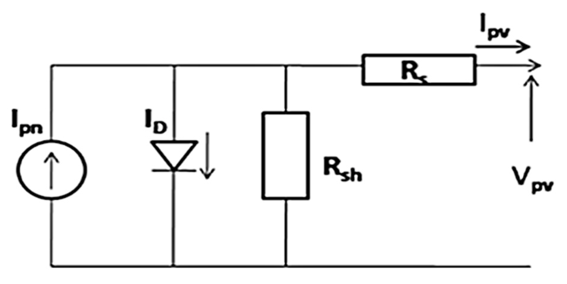
The block of the system is shown in Figure 1. The PV panel is formed by the series and parallel connection of the PV modules. For the case study, the power capacity of a solar PV panel is 51 kW with 406 V DC voltage. To obtain 51 kW power from the panel, there are 17 parallel strings,   N P and 14 series modules,   N s per string in the PV array. The selection of a number of series modules (Ns) is based on the voltage at the maximum power point, Vmp, and output DC voltage, Vdc [22]. The number of strings is determined by the current at the maximum power point Imp by (1) and (2). Pmax is the maximum power capacity to be maintained [23]. The basic electrical equivalent diagram is shown in Figure 2. I m p is the current at the maximum power point.
N s = V d c V m p
N P = P m a x / V d c I m p

2.2. DC-DC Boost Converter

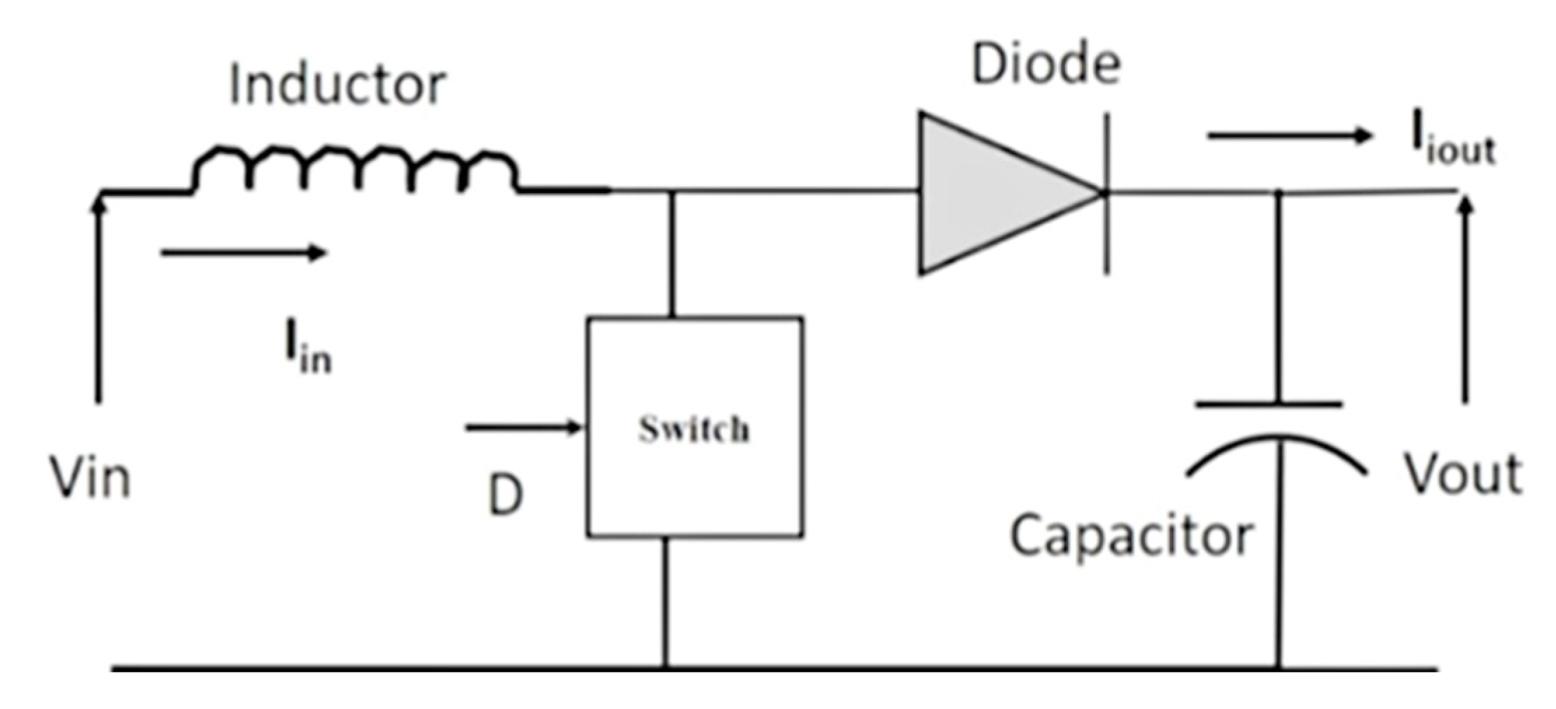
The basic functional block diagram is shown in Figure 3. The output of the solar PV panel is given to the DC-DC converter. The function of this converter is to step up the input voltage to a higher level. The operation of the converter is based on the maximum power transfer theorem. It works on the impedance matching concept: when the internal resistance of the PV panel and equivalent resistance of the DC-DC converter looking into the output terminals of the PV panel matches one another, maximum power transfer can happen from the PV panel to the DC-DC converter [24].
The working of the DC-DC converter is controlled by the duty cycle provided by the MPPT controller. The selection of the DC-DC converter is obtained, by (3), (4) and (5). L d c l i n k and C d c l i n k are the DC link inductor (H) and capacitor (F).
D = 1 v i n v o
L d c l i n k = V i n V o V i n f s w ( Δ I V o )
C d c l i n k = I i n V o V i n f s w Δ V V o
D is known as the duty cycle. v o is the output voltage of the boost converter, and V i n is the input voltage of the boost converter from the PV panel. Δ I is the ripple factor in the current and Δ V is the ripple factor in the voltage. f s w is the switching frequency of the converter switch in Hz [25].

2.3. Three-Phase Two-Level Inverter (DC-AC Converter)

In the following case study, the selected two-level three-phase inverter of 51 kW power capacity is built by using six IGBT power electronics switches [26]. The operation of the IGBTs is controlled by the sinusoidal pulse width modulation (SPWM) technique. The AC output of the inverter is obtained by controlling the ON and OFF state of the IGBT switches [27]. This ON and OFF state of the switches is managed by the proper generation of the gate pulses of the switches through an inverter controller. The inverter AC output voltage is 380 V (line voltage).

3. Background: General Introduction

The electrical energy generation by solar photon energy using a photodiode is easy. Solar power generation is attracting more attention due to its ease in installation and also because electrical power can be generated at different levels. Demand for electrical energy, due to the modernization of society and the digitalization of industry, has resulted in an increase in the number of installations of solar PV panels. These are connected to the load to supply power. The excess power generation is fed into the grid. Power electrics play important role in power transformation in grid-tied and standalone solar PV systems. Because of this connection, power quality challenges are introduced into the grid [28]. To ensure power quality, the role of the controller is important. In the following sections, the design and implementation of the MPPT and inverter control law have been explained regarding the control of a solar PV system [29].

4. Proposed Work

The proposed work explains the application of the adaptive LMS algorithm to develop the MPPT controller and inverter control law. The adaptive LMS algorithm is applied in two different controllers. In an adaptive MPPT controller, the solar PV panel is predicted by using the LMS concept, and later, it is compared with the previous power. The result of this comparison is the error function, which is used to update the predicted power and, accordingly, the duty cycle is adjusted to the DC-DC boost converter.
The inverter control algorithm is modified by implementing the adaptive LMS algorithm. The synchronous reference frame, which is the d-q transformation control algorithm, is used for the development of the inverter control law. The grid reference currents are extracted from the control law to generate the gate pulses for switches used in the three-phase inverter to control the total harmonics in the grid and load currents under different linear and non-linear load conditions. The proposed developed adaptive LMS control law is based on a Synchronous Reference Frame (SRF). The advantage of the SRF is that it does not require unit vector calculation. A lesser number of equations is required to build the control law.

4.1. Adaptive LMS Theory

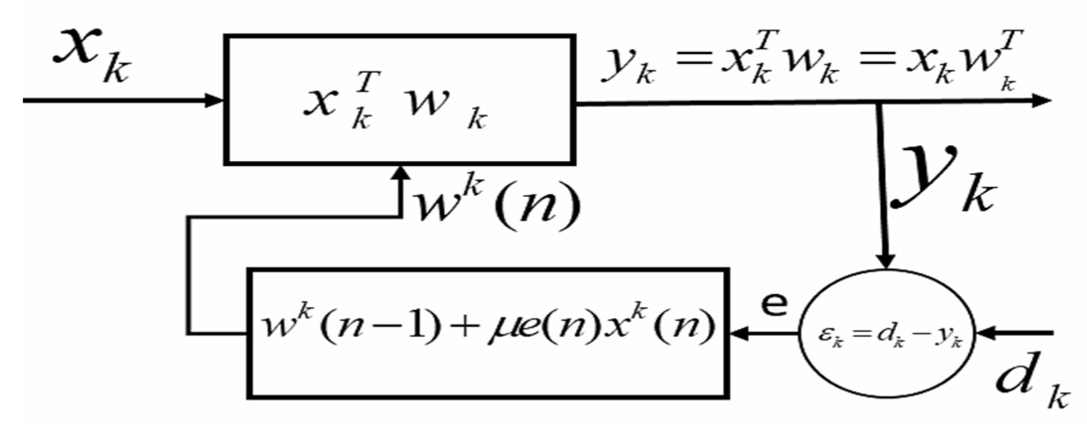
The adaptive LMS implementation is shown in Figure 4.
The adaptive theory explains the updating of the weight according to the changes in the systems [30]. This weight updating depends on the error function. The weight values are changed to minimize the error function. The output function is managed by updating the weight function to minimize the error. The error is measured by comparing the actual output, y n and desired output, d n . The optimized weight function, w n is found by finding the least mean square values of the error function, e n . The adaptive LMS concept is explained in Equations (6)–(8). The increment size of the weight function is   μ . It is also known as the learning rate of an algorithm. The range of increment size is 0 < μ < 2 γ m a x , where γ m a x indicates the maximum value of eigenvalues. The larger size reduces the convergence rate and sometimes leads to inappropriate results. The smaller the increment size, the slower the convergence rate. It could be a variable step size. In the presented work, it is selected as being between 0.1 to 0.9 for the simulation, as mentioned in [11,19]:
y n = w n T x n
The error is determined by finding the difference between the desired signal, d(n) and the actual signal, y(n) as expressed in (7):
e n = d n y n
The weight function, w k n + 1 is updated at the kth iteration and instant ‘n’, as given in (8), where μ is an increment size [13]:
w k n + 1 = w k n + μ e n x k n
The mean square error is obtained by (9):
e n 2 = d n y n 2

4.2. Control Algorithm

The control algorithm used to develop an adaptive LMS control law is the SRF theory. The sensed grid voltage phase angle is found by the PLL block [31]. The sensed three-phase load current is transformed into d-q components by the Clark-perk transformation concept with respect to the phase angle. The adaptive control law is developed by applying the LMS algorithm with the SRF control algorithm and as explained in Section 4.5.

4.3. Implementation of an Adaptive LMS Algorithm

The MPPT and inverter controllers are two important controllers that control the parameters on the solar PV panel and grid side, respectively, in the grid-connected solar PV system. The P&O MPPT controller is modified by applying the adaptive LMS algorithm, as explained in Section 5. The development of an adaptive LMS MPPT is discussed in Section 4.4. Similarly, the adaptive LMS control law as an inverter controller is discussed in Section 4.5.

4.4. Adaptive LMS MPPT Controller

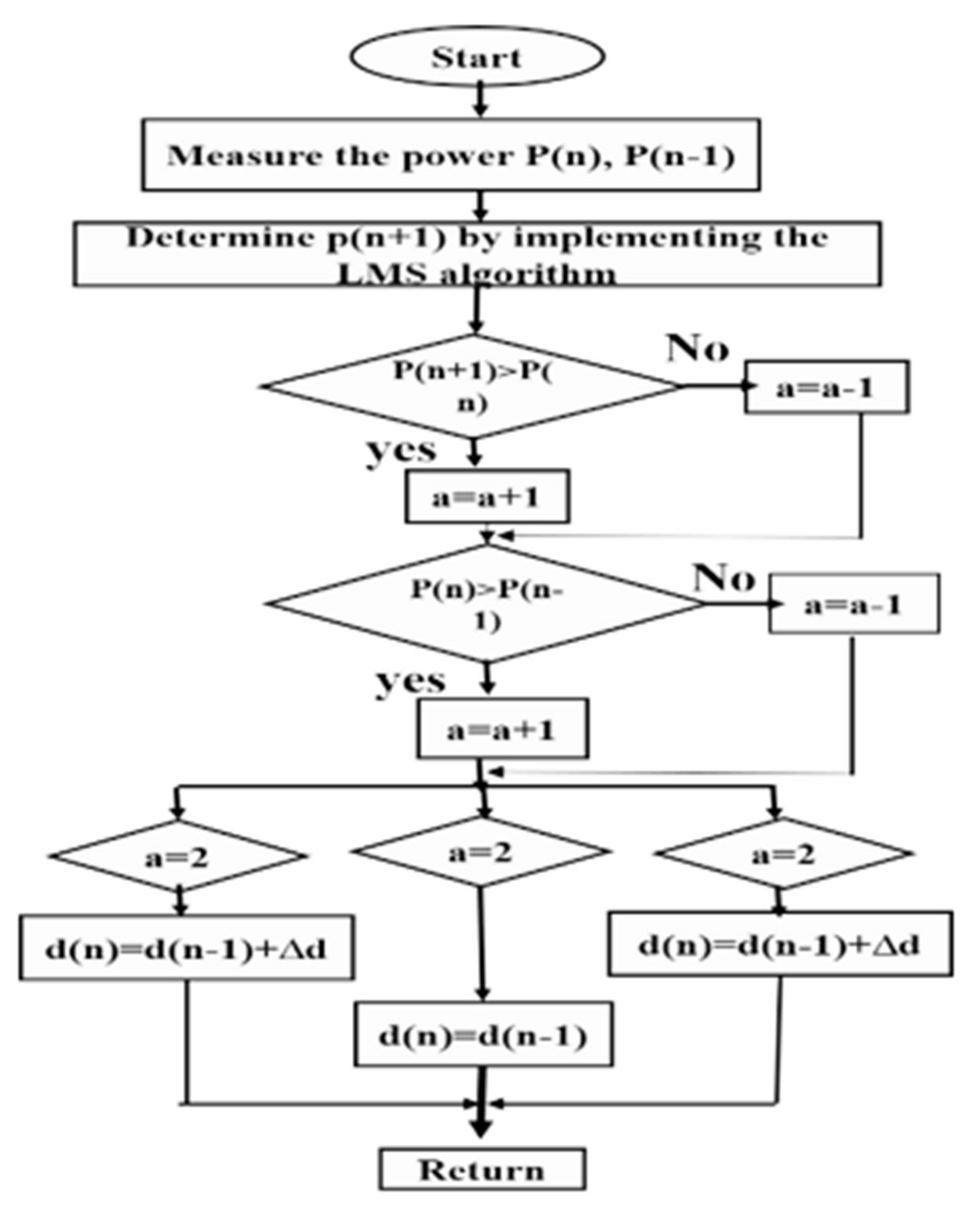
The weight function is updated for a fixed iteration to update the power function. The development of an adaptive controller is shown in the following flow chart, Figure 5.
The MPPT controller is used to obtain the duty cycle for a reference voltage to extract the maximum power from the PV panel. P(n + 1) is the power predicted by applying the adaptive LMS concept as explained in (11). The error is found by (10), and accordingly, the predicted power is determined by (11) to minimize the error. µ is the incremental step size in (11). Its value is in the range of 0.1 to 0.2 [32]. e p n is the error between the actual PV power, P n and the previous power,   P n 1 . The increment size μ is selected as 0.1 [13]:
e p n = P n P n 1
The future PV power, P n + 1 , is predicted by (11):
P n + 1 = P n 1 + 2   μ   e p n   P n

4.5. Adaptive LMS Control Law—An Inverter Controller

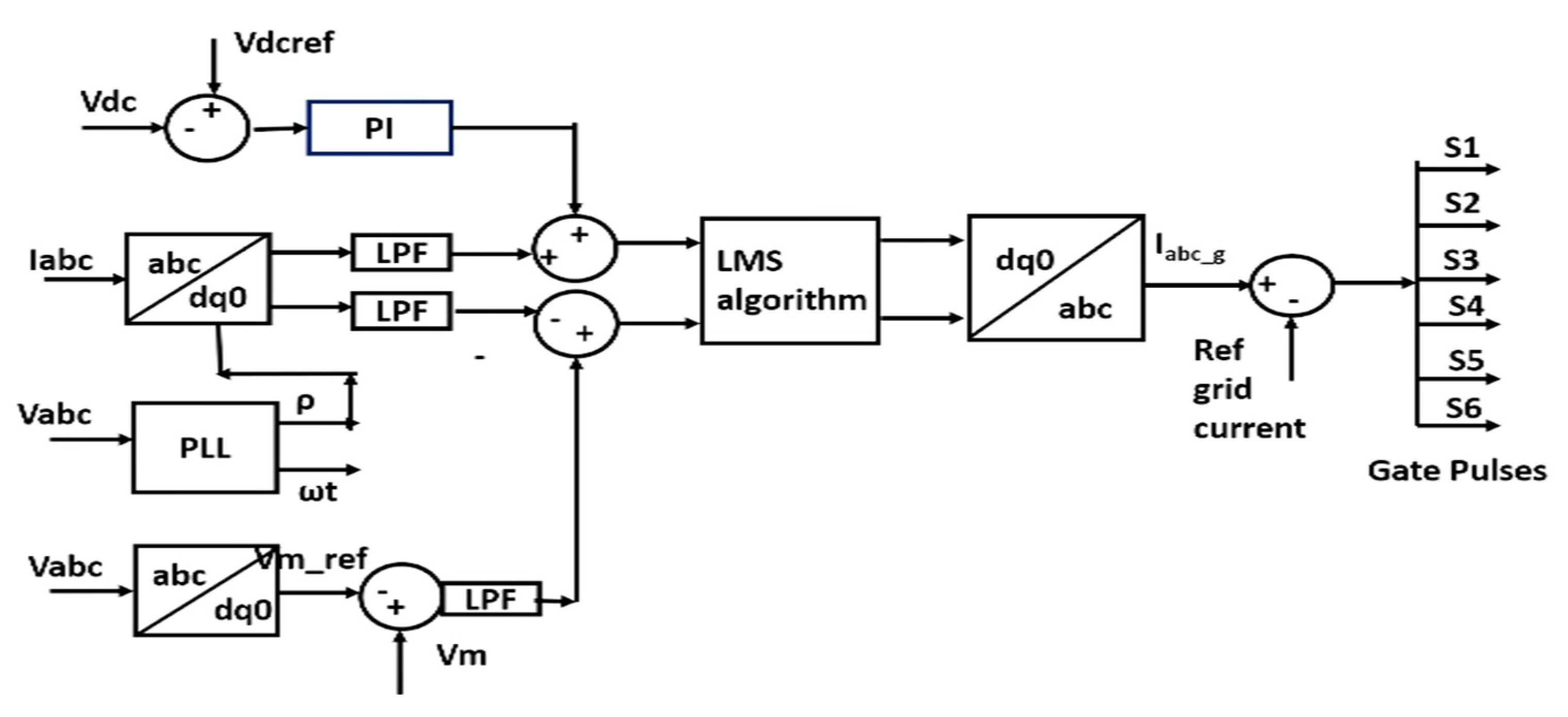
Instead of using the PI controller, the gate switching pulses are generated by using a control scheme based on an adaptive LMS algorithm, so it is known as the adaptive LMS control law. The development of the control law is expressed in Figure 6.
The objective is to extract the fundamental component of the gate current and compare it to the actual grid current to reduce the harmonics in the grid current. The grid voltage is sensed at the interconnection point of the grid, load and inverter. This voltage is converted into the α-β phase system. The phase angle ƍ is obtained by (12) and (13). Vα and Vβ are alpha-beta components of grid voltage [33]. The d-q components of load current and grid current with respect to phase angle ƍ are found by (14). The procedure is divided into four steps:
  • Obtain the d-q component of the grid voltage, grid current and load current.
  • Determine the dc reference current from the dc link voltages.
  • Apply the adaptive LMS algorithm to extract the reference fundamental load current.
  • Generate switching gate pulses by comparing steps 2 and 3.
V α V β = V a V b 2 V c 2 3 V b 2 3 V c 2
Va, Vb and Vc are phase voltages of phases a, b and c. The phase angle, ρ , of the grid voltage is obtained by (13):
ρ = w t = cos 1 V a V b 2 V c 2 3 V b 2 3 V c 2
Direct component,   I d , and a quadrature component ,   I q , of the load currents are obtained by (14):
I d I q = cos ρ sin ρ sin ρ cos ρ 1 1 / 2 1 / 2 0 3 2 3 2 I a I b I c
I d is the DC reference current (15) and is obtained through the proportional-integral (PI) controller whose input is the voltage error, V d c e , between the measured DC link voltage, v d c l i n k   and the reference dc link voltage, v d c l i n k   r e f [34]. The base values for the gains of PI controllers are selected from [11], and later, they are changed via the trial-and-error method (Kp = 0.5 and KI = 1).
I d , the DC reference current is determined by (15):
I d = V d c e K p + K I V d c e d t
V d c e = v d c l i n k v d c l i n k   r e f
The instantaneous error at the kth instant is determined from the sensed grid current and the weighted current for the d-q component by applying the adaptive LMS algorithm concept in Section 3. The weighted component of the load current has been evaluated (17), (18) as W(n), which is the weight function of the load current. e d n is the error between the d-component of the actual load current and the d-component of the reference grid current. ƞ is the step size in the weight function. Similarly, the q-component of the reference current is obtained by (20)–(22). Iq is the q-component of the load current. I d = I d c _ r e f n and I q n = 0 .
The following Equations (17)–(19) are the d-component of the reference current:
e d n = I d w n I d c _ r e f n
w n = w n 1 + ƞ e d n I d c _ r e f n
I d n = w n I d n
The following Equations (20), (21) and (22) are the q-component of the reference current:
e q n = I q w n I q n
w n = w n 1 + η e n I q n
I q n = w n I q n
The generated reference components are transformed into an a-b-c three-phase form. These are used to generate switching gate pulses for the multifunctional inverter [35].

5. Result

The adaptive LMS MPPT controller and adaptive control law were implemented for the control of the solar PV system. The performance was observed for the condition given below:
  • Change in non-linear load.
  • Input: variation in solar radiation.
  • Change in sampling time.
  • Change in step size, Ƞ.
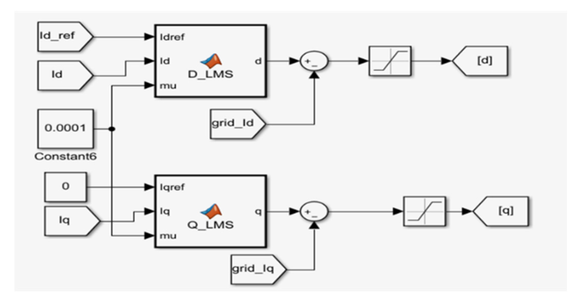
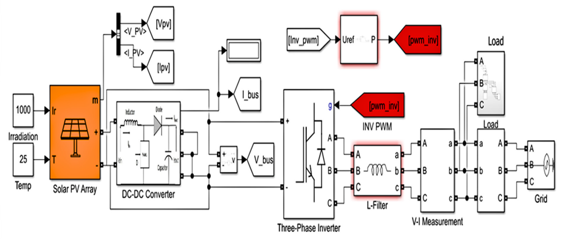
The model was built on the computer system of the configurations having an Intel(R) Core (TM) i3-4030U CPU @ 1.90 GHz, 64-bit operating system, x64-based processor and 8.00 GB RAM. Figure 7 expresses the MATLAB Simulink implemented model of an adaptive LMS control law. A detailed diagram of the MATLAB Simulink model of the solar PV system with an adaptive LMS controller is shown in Figure 8. The module configuration details are given in Table 2.
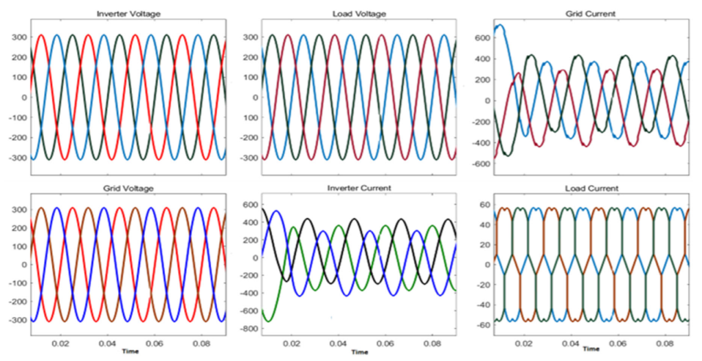
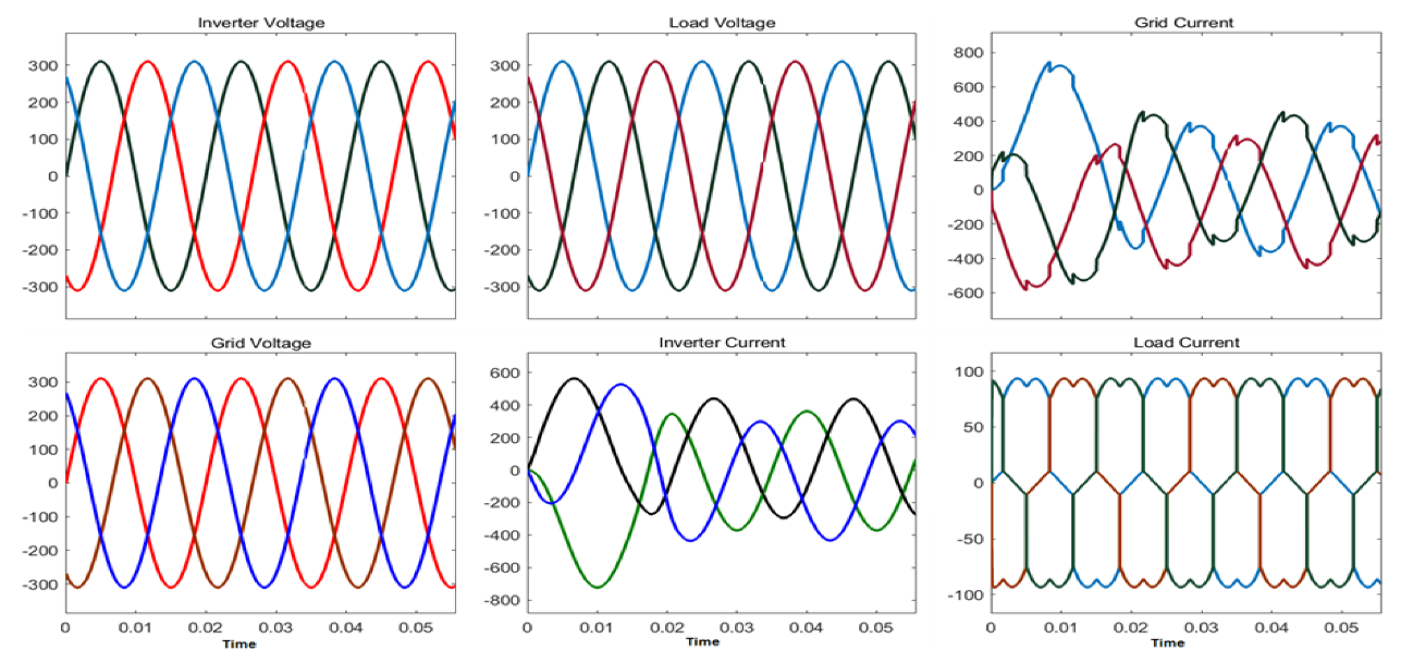
The voltage and current performance of the solar PV system under nonlinear load and linear load are shown in Figure 9 and Figure 10.
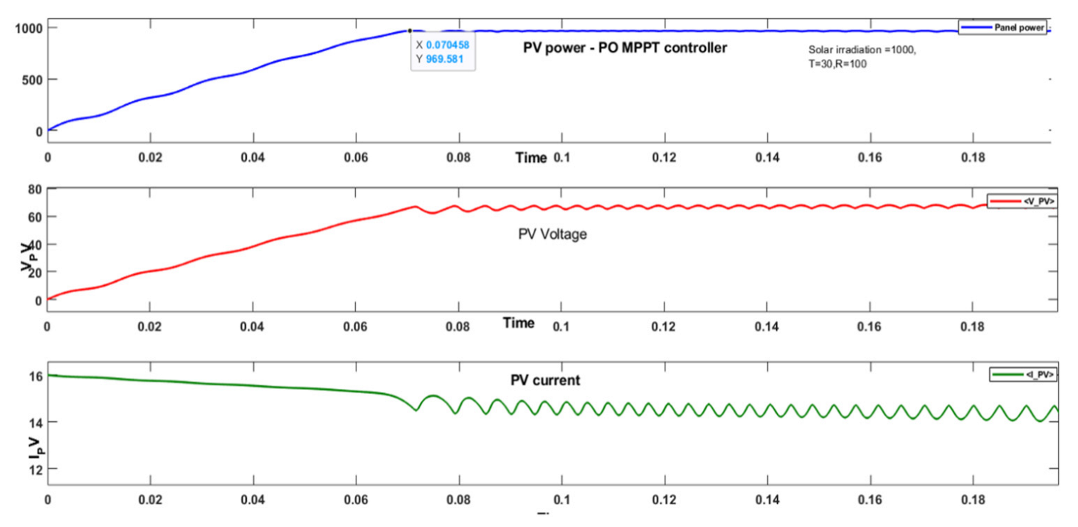
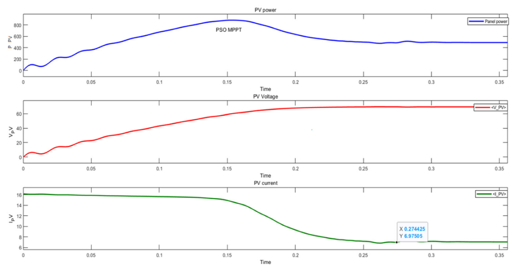
The performance is measured in terms of settling time, peak overshoot and steady-state error. The P&O MPPT, PSO MPPT and adaptive LMS MPPT controllers were implemented to extract the PV power from a solar PV panel with a capacity of 858 Watts, 69 V dc voltage. The responses of the PV power, PV voltage and PV current of the solar PV panel for the three MPPT controllers are shown in Figure 11, Figure 12 and Figure 13. The adaptive LMS MPPT controller and adaptive control law as the inverter controller are implemented for the solar photovoltaic system configured in Table 3.
The total harmonics distortion (THD in%) is investigated for different linear and nonlinear loads, sampling time, and the step size of weight updating. The controller performance is measured in terms of the settling time of the current response.

6. Discussion

6.1. Variation in Input Solar Irradiation, Non-Linear Load, Sampling Time, Variation in Step-Size

The selected step size is 0.0001, 0.001 and 0.01. The sampling time should be greater than 30 µs. There is a tradeoff between the step size and sampling time over the simulation run time, and better results. The number of iterations in algorithm execution is 75. The results were found to be better for step sizes 0.01 and 0.001 compared with 0.0001. The current response is stable for these two-step size values. It was also observed that the current response is stable when the step size is between 0.01 and 0.9. The selected sampling time was 40 µs. For a step size value less than 0.001, the current response was not settled at the final value under nonlinear load (P = 10 kW and Q = 200 VAR), Table 4. The THD of the grid current and load current was measured as 6.28 and 23.85, respectively.
The sampling time was varied from 40 µs to 50 µs with a constant step size of 0.001; the grid current THD was reduced from 3.22 to 2.5. Similarly, the load current THD was reduced from 19.88 to 7.14%; whereas, the settling time was increased from 0.525 s to 0.8 s with an increase in sampling time. This was observed under the load condition (P = 10 kW and Q = 100 VAR).
With the change in step size from 0.001 to 0.01 and a constant sampling time of 50 µs, the settling time was increased from 0.8 s to 0.9 s. There was no change in grid current and load current THD under load conditions P = 10 kW and Q = 100 VAR, Table 4.
The selection of sampling time and step size of the weight function was dependent on load condition. At the value of µ = 0.001 and a sampling time of 40 µs, the best tradeoff was observed in terms of a reduction in total harmonics distortion in the grid current and a settling time of the current response under (P = 10 KW and Q = 200 VAR). Similarly, at the value of µ = 0.001 and a sampling time of 50 µs, the best tradeoff was observed in terms of a reduction in total harmonics distortion in the grid current and a settling time of the current response under (P = 10 kW and Q = 100 VAR).

6.2. Variation in Linear Load with Constant Solar Irradiation Input

With a sampling time of 40 µs, the input solar irradiation was constant at 1000 W/m2, step size was 0.01, and the grid current THD was reduced from 4.75 to 3.22% with an increase in linear load, as shown in Table 5. Similarly, there was more reduction in the load current THD from 19.64 to 7.11%.

6.3. Comparative Analysis for Two Different Combinations of MPPT and Inverter Controller

The comparative analysis for two different combinations of MPPT and inverter controller for non-linear load (10 kW linear connected in parallel with Rectifier with R = 10 kW and Q = 100 VAR) and variation in solar radiation 0 to 1000 W/m2 is recorded in Table 6.
The adaptive LMS MPPT controller and inverter control law proves that there is a reduction in the grid and load current total harmonic distortion. The total harmonics reduction due to adaptive LMS algorithm implementation with the MPPT and inverter control law in grid current and load current is reduced from 4.75% to 3.25% and from 19.89 to 19.64%, respectively, compared to the PO MPPT controller and adaptive control law for the control of a solar PV system.

6.4. Comparative Analysis with Other Author Researcher Results

Comparative analysis for total harmonics distortion in the grid and load current of proposed work and prior research work related to adaptive LMS algorithm families for the solar PV system is tabulated in Table 7. The DC link voltage and current are stable and are very close to their final value due to the P&O and adaptive LMS MPPT controllers.
The control law based on i-PNLMS and the proposed work helped to reduce the percentage of the THD in the grid voltage. The PNKLMF-NN technique showed a reduction in %THD in the grid current. The VSSLMS technique is suited to lessen the %THD in the grid current. The VP-RZA-LMF control law is more effective in reducing the THD in the grid current and voltage. The Wiener filter controller and LMF also proved that the control of THD is possible for solar PV systems. Compared with all LMS family controllers, the adaptive LMS control law shows better performance in controlling the solar PV system. The result shows that with the proper selection of step size, sampling time, and the number of iterations, there is a drastic reduction in %THD in grid current, grid voltage and load current. According to the IEEE standards 519-2014, the %THD of the load current should be below 25%, %THD in grid current < 5%, and %THD in grid voltage < 5%.

6.5. Comparative Analysis of the Three MPPT Controllers Implemented for Solar PV Panel

The adaptive LMS MPPT controller was implemented for the solar PV system and the results compared with the perturbation and observation MPPT, and PSO MPPT Controllers. The developed MPPT controllers were implemented on a solar PV system whose specifications are mentioned in Table 8.
In Table 9, the tracking speed of the PSO MPPT is faster than the other two MPPT controllers. It reaches the final value of power at 0.0963 s, but it experiences oscillations at the final value of the PV power and overshoot. Whereas, the PV power tracking by the P&O MPPT is very close to the rated value of the PV power, with a moderate speed compared to the PSO MPPT and it is faster than the LMS MPPT controller.
The only thing is that it fluctuates at the final value of the maximum power point. Its settling time is 0.18 s to reach peak power. Whereas the settling time due to the LMS MPPT controller is 0.33 s, which is more than the other two MPPT controllers. The power steady-state error due to the LMS MPPT controllers is 0.7% (6 watt) less compared with the PSO MPPT controllers, and nearly the same as the PO MPPT controller. Table 10. explains the PV panel voltage, current and power at final value due to these three MPPT controllers, among these, the adaptive LMS MPPT controller gives optimal solutions.
Table 9 shows that the LMS MPPT controller gives an optimal solution compared with tracking the PV power, with less steady-state and zero oscillations at the optimal peak value of power, with a tradeoff of more settling time. The transient and steady-state performance of the three MPPT controllers is summarized in Table 11.
There are fluctuations in the PV power response due to the P&O MPPT controller and overshoot (2.6%) due to the PSO MPPT controller. There are no oscillations or overshoot in the PV power response due to the adaptive LMS MPPT controller. The settling time of the PV power response is compared to the P&O and PSO MPPT controllers. The steady-state error in power response is less (0.06%) due to the adaptive LMS and P&O MPPT control compared with the PSO MPPT controller. The PV response obtained by an adaptive LMS MPPT controller is slow, but it does not exhibit the oscillation and peak overshoot.

6.6. Findings

The adaptive least mean square algorithm can be customized to develop the control law as well as the MPPT controller. The adaptive LMS algorithm is simple and easy to implement for the development of the controller. The adaptive control law has a certain advantage over the inverter PI controller. The effective results are dependent on the selection of the sampling time, step size of weight function, number of iterations in algorithm execution, and the switching frequency of the DC-DC converter and inverter. The hardware configuration is also one of the important factors required to achieve the result. A high-speed processor completes the tasks in less time due to the increase in processing time. This allows for the addition of more iterations of algorithm computations.

7. Conclusions

The adaptive LMS control law is developed using the LMS algorithm. This algorithm uses the error function that determines the error between the actual value and the reference value. Thus, it saves the burden of the random initialization of parameters. This algorithm is used in two ways in this proposed work. Firstly, to predict the PV power in an adaptive LMS controller and to extract the reference grid current in the adaptive control law. It is observed that voltage and current waveforms are sinusoidal in nature. The proper tradeoff between sampling time, step size of weight function, and switching frequency need to be achieved to obtain effective results in the reduction in total harmonic distortion of the grid current and load current and reduce the settling time of the response. A comparative analysis for the two different combinations of MPPT and inverter controller non-linear load showed that the THD reduction in grid current (4.75% to 3.22%) and load current (19.89% to 19.64%) were found to be better on implementation of the controller with an adaptive LMS algorithm, as shown in Table 5. For the step size 0.001 and sampling frequency 50 μs, the total harmonics distortion in the grid current and load current are 2.95% and 7.11% less than the IEEE 519 standards under nonlinear load, whereas the settling time is increased (0.8 s). The THD reduction in grid current (3.22%) and load current (19.88%) due to the implementation of the adaptive LMS control law is noticeable compared to other LMS family control laws, as explained in Table 7. The implementation of an adaptive LMS algorithm with an MPPT controller and inverter control law controls the total harmonic distortion in the grid and load currents under linear and nonlinear load conditions. Furthermore, the performance of the adaptive LMS MPPT controllers is better at tracking the optimal power point with less error at 0.7% (6 W). Therefore, the LMS algorithm can be customized as per the application to control and improve the results of solar PV systems. The LMS algorithm performs better at 0.01 step size of weight adaptation.

8. Future Scope

In the presented work, the selected reference quadrature current is made equal to zero. This value can be found by using the actual grid voltage and reference grid voltage to achieve a more precise result in a reduction in total harmonic distortion in the grid and load current. The LMS family algorithm can be applied to develop the controller.
The adaptive MPPT controller may be developed by applying the other LMS family algorithms for the control of a solar PV system. The same controllers may be applied to the wind plane.
The performance of the controllers may be tested by implementing them on a DSP processor and varying the switching frequency of the inverter and DC-DC converter.

Author Contributions

The paper investigation, resources, data curation, writing—original draft preparation, writing—review and editing, and visualization were performed by N.K. and D.K. The paper conceptualization and software were conducted by S.N.P. and V.D. The validation and formal analysis, methodology, supervision, project administration, and funding acquisition of the version to be published were conducted by R.P.d.P. and P.B.D. All authors have read and agreed to the published version of the manuscript.

Funding

This research is supported by the Spanish Andalusian Research Project P18-RT-4040.

Institutional Review Board Statement

Not applicable.

Informed Consent Statement

Not applicable.

Data Availability Statement

Not applicable.

Conflicts of Interest

The authors declare no conflict of interest.

Nomenclature

TitleAbbreviation
Alternating currentAC
Active power (watt)P
Direct CurrentDC
Fast fourier transformFFT
Finite impulse response FIR
HertzHz
KilowattkW
Least mean squareLMS
Grid voltage Vabc
Load currentIabc
Maximum power point trackingMPPT
Phase lock loopPLL
Particle swarm optimizationPSO
Perturbation and observation P&O
Photovoltaic PV
Reactive power (volt-ampere-reactive)Q
Step size in the adaptive control lawƞ
Temperature unit degree Celsius °C
Total harmonic distortionTHD
Volt-ampere-reactiveVAR

References

  1. Iweh, C.D.; Gyamfi, S.; Tanyi, E.; Effah-Donyina, E. Distributed Generation and Renewable Energy Integration into the Grid: Prerequisites, Push Factors, Practical Options, Issues and Merits. Energies 2021, 14, 5375. [Google Scholar] [CrossRef]
  2. Math, H.J.; Fainan Hassan, B. Integration of Distributed Generation in the Power System; John Wiley & Sons: Hoboken, NJ, USA, 2018; pp. 324–326. [Google Scholar]
  3. Patel, H.; Gajjar, R.; Pandya, R. Artificial Intelligence Based MPPT techniques for Solar V System: A Review. J. Emerg. Technol. Innov. Res. 2019, 8, 1043–1059. [Google Scholar]
  4. Arfeen, Z.A.; Khairuddin, A.B.; Larik, R.M.; Saeed, M.S. Control of distributed generation systems for microgrid applications: A technological review. Int. Trans. Electr. Energ. Syst. 2019, 29, e12072. [Google Scholar] [CrossRef] [Green Version]
  5. Anvarsha, M.; Otto, O. A Variable Step Size Adaptive LMS Algorithm Implementation for MPP Tracking In Solar PV System. Int. J. Adv. Res. Electr. Electron. Instrum. Eng. 2014, 3, 346–351. [Google Scholar]
  6. Julie, V.; Robles-Algarín, C.; Restrepo-Leal, D. Novel Approach for an MPPT Controller Based on the ADALINE Network Trained with the RTRL Algorithm. Energies 2018, 11, 3407. [Google Scholar] [CrossRef] [Green Version]
  7. Zakaria Mohamed Salem, E.; Lrahman Alranini, M.A. Review of maximum power point tracking algorithms of the PV system. Front. Eng. Built Environ. 2021, 1, 68–80. [Google Scholar] [CrossRef]
  8. Naki, G.; Irmak, E. MPPT-Based Model Predictive Control of Grid-Connected Inverter for PV Systems. In Proceedings of the 2019 8th International Conference on Renewable Energy Research and Applications (ICRERA), Brasov, Romania, 3–6 November 2019; ISBN 978-1-7281-3587-8/19. [Google Scholar]
  9. Pallavi, V.; Mahajan, P. Smooth LMS-based adaptive control of SV system tied to the grid for enhanced power quality. IET Power Electron. 2020, 13, 3456–3466. [Google Scholar]
  10. Chintapalli Satya, P.; Srinivasarao, M. SignRegressor Least Mean Square Control Algorithm and Adaptive P &O Algorithm for Single Stage PV system Integrated with Power Grid. Int. J. Progress. Res. Sci. Eng. 2021, 2, 66–71. [Google Scholar]
  11. Avdhesh, K.; Garg, R. Control of Grid Integrated Photovoltaic System using new Variable Step Size Least Mean Square adaptive filter. Electr. Eng. 2021, 103, 2945–2959. [Google Scholar]
  12. Manoj Badoni, A.; Kumar Singh, A. Grid Tied Solar PV system with Power Quality Enhancement Using Adaptive Generalized Maximum Versoria Criterion. CSEE J. Power Energy Syst. 2021, 1–10. [Google Scholar] [CrossRef]
  13. Eugene, W.; Widrow, B. The least mean fourth LMF adaptive algorithm and its family. IEEE Trans. Inf. Theory 1984, 30, 275–283. [Google Scholar]
  14. Agarwal, R.K.; Hussain, I.; Singh, B. LMF-Based Control Algorithm for Single Stage Three-Phase Grid Integrated Solar PV System. IEEE Trans. Sustain. Energy 2016, 7, 1379–1387. [Google Scholar] [CrossRef]
  15. Neha, B.; Hussain, I.; Singh, B. Implementation of DSTATCOM with i-PNLMS Based Control Algorithm under Abnormal Grid Conditions. IEEE Trans. Ind. Appl. 2018, 54, 5640–5648. [Google Scholar] [CrossRef]
  16. Rahul Kumar, A.; Hussain, I. Application of LMS-Based NN Structure for Power Quality Enhancement in a Distribution Network Under Abnormal Conditions. IEEE Trans. Neural Netw. Learn. Syst. 2017, 29, 1598–1607. [Google Scholar] [CrossRef]
  17. Sachin, D.; Singh, B. Design and Performance Analysis of Three-Phase Solar PV Integrated UPQC. In Proceedings of the IEEE 6th International Conference on Power Systems (ICPS), New Delhi, India, 4–6 March 2021; pp. 1–10. [Google Scholar]
  18. Varshney, G.; Chauhan, D.S.; Dave, M.P. Unit Template-based Control of PV DSTATCOM. Recent Adv. Electr. Electron. Eng. (Former. Recent Pat. Electr. Electron. Eng.) 2019, 12, 36–42. [Google Scholar] [CrossRef]
  19. Satish, C.; Dash, B. Comparative Analysis of LMS Based Control Algorithms for Grid Integrated System Innovation. In Electrical Power Engineering, Communication and Computing Technology; Springer Nature: Singapore, 2021; Volume 630. [Google Scholar] [CrossRef]
  20. Das, S.R.; Hota, A.P.; Pandey, H.M.; Sahoo, B.M. Industrial power quality enhancement using fuzzy logic based photovoltaic integrated with three-phase shunt hybrid active filter and adaptive controller. Appl. Soft Comput. 2022, 121, 108762. [Google Scholar] [CrossRef]
  21. Touheed, K.; Asim, M.; Saood Manzar, M.; Ibrahim, M.; Sadaf Afzal Ahmed, S. Least mean sixth control approach for a three-phase three-wire grid-integrated PV system. Int. J. Power Electron. Drive Syst. (IJPEDS) 2021, 12, 2131–2139. [Google Scholar] [CrossRef]
  22. Banik, A.; Shrivastava, A.; Potdar, R.M.; Jain, S.K.; Nagpure, S.G.; Soni, M. Design, modelling, and analysis of novel solar PV system using MATLAB. Mater. Today Proc. 2022, 51, 756–763. [Google Scholar] [CrossRef]
  23. Winston, D.P.; Karthikeyan, G.; Pravin, M.; JebaSingh, O.; Akash, A.G.; Nithish, S.; Kabilan, S. Parallel power extraction technique for maximizing the output of solar PV array. Sol. Energy 2021, 213, 102–117. [Google Scholar] [CrossRef]
  24. Uthirasamy, R.; Chinnaiyan, V.K.; Vishnukumar, S.; Karthick, A.; Mohanavel, V.; Subramaniam, U.; Muhibbullah, M. Design of boosted multilevel DC-DC converter for solar photovoltaic system. Int. J. Photoenergy 2022, 2022, 1648474. [Google Scholar] [CrossRef]
  25. Jenisha, C.M. Decoupled Control with Constant DC Link Voltage for PV-Fed Single-Phase Grid Connected Systems. In Integration of Renewable Energy Sources with Smart Grid; Wiley: Hoboken, NJ, USA, 2021; pp. 171–185. [Google Scholar] [CrossRef]
  26. Cardoso, J.; Orosco, R.; Vazquez, N.; López, H.; Hernandez, C.; Vaquero, J. High Efficiency Transformerless Photovoltaic DC/AC Converter with Common Mode Leakage Current Elimination: Analysis and Implementation. Energies 2022, 15, 3177. [Google Scholar] [CrossRef]
  27. Brahmi, H.; Dhifaoui, R. A Study of a DC/AC Conversion Structure for Photovoltaic System Connected to the Grid with Active and Reactive Power Control. Complexity 2021, 2021, 9967577. [Google Scholar] [CrossRef]
  28. Tian, L.; Huang, Y.; Liu, S.; Sun, S.; Deng, J.; Zhao, H. Application of photovoltaic power generation in rail transit power supply system under the background of energy low carbon transformation. Alex. Eng. J. 2021, 60, 5167–5174. [Google Scholar] [CrossRef]
  29. Mulenga, E.; Bollen, M.H.; Etherden, N. Distribution networks measured background voltage variations, probability distributions characterization and Solar PV hosting capacity estimations. Electr. Power Syst. Res. 2021, 192, 106979. [Google Scholar] [CrossRef]
  30. Parida, A.; Subudhi, B. A Variable Step Size Robust Least Mean Logarithmic Square-Based Control Scheme for Improved Power Quality of Grid-Interfaced PV System. IEEE Trans. Smart Grid 2022, 13, 2086–2093. [Google Scholar] [CrossRef]
  31. Sibanyoni, M.; Chowdhury, S.D.; Ngoma, L.J. Single phase inverter fuzzy logic phase locked loop. In Microgrid Technologies; Wiley: Hoboken, NJ, USA, 2021; pp. 91–120. [Google Scholar] [CrossRef]
  32. Chankaya, M.; Hussain, I.; Ahmad, A.; Malik, H.; Garcia Márquez, F.P. Multi-Objective Grasshopper Optimization Based MPPT and VSC Control of Grid-Tied PV-Battery System. Electronics 2021, 10, 2770. [Google Scholar] [CrossRef]
  33. Qais, M.H.; Hasanien, H.M.; Alghuwainem, S. A novel LMSRE-based adaptive PI control scheme for grid-integrated PMSG-based variable-speed wind turbine. Int. J. Electr. Power Energy Syst. 2021, 125, 106505. [Google Scholar] [CrossRef]
  34. Veeramanikandan, P.; Selvaperumal, S. Investigation of different MPPT techniques based on fuzzy logic controller for multilevel DC link inverter to solve the partial shading. Soft Comput. 2021, 25, 3143–3154. [Google Scholar] [CrossRef]
  35. Chandrasekaran, K.; Sahayam, J.J.; Thanasingh, S.J.; Ramalingam, S.; Fayek, H.H.; Ravichandran, N.; Rusu, E. Performance of Multifunctional Smart PV-Based Domestic Distributed Generator in Dual-Mode Operation. Machines 2021, 9, 356. [Google Scholar] [CrossRef]
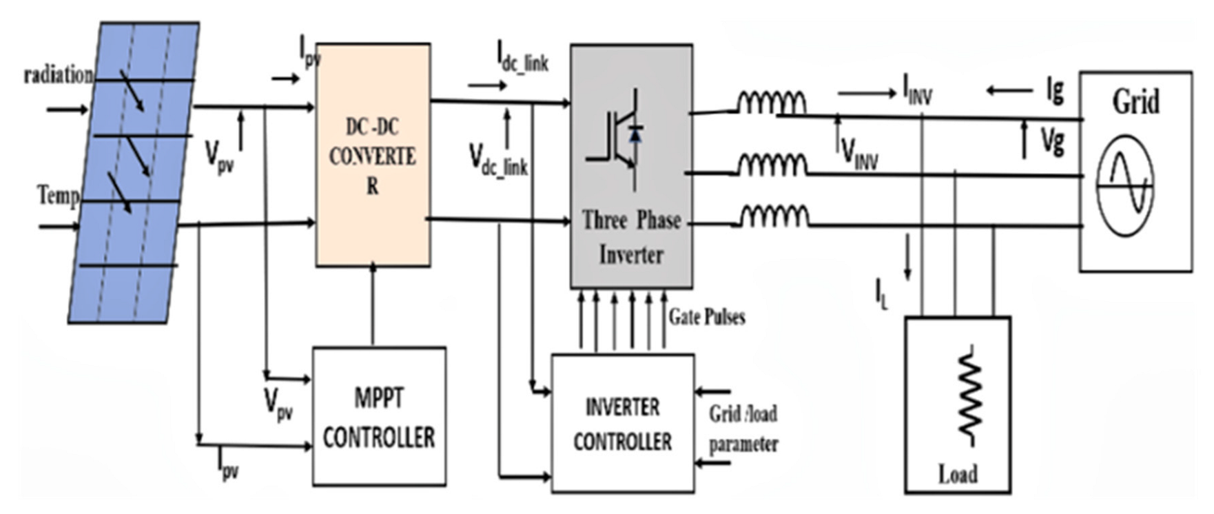
Figure 1. Block diagram of solar photovoltaic system.
Energies 15 08909 g001
Figure 2. The equivalent electrical circuit of the PV cell.
Energies 15 08909 g002
Figure 3. The block diagram of the DC-DC boost converter.
Energies 15 08909 g003
Figure 4. Adaptive LMS FIR structure.
Energies 15 08909 g004
Figure 5. Flow chart of the adaptive LMS MPPT controller.
Energies 15 08909 g005
Figure 6. Synchronous reference frame theory for implementation of an adaptive LMS control law.
Energies 15 08909 g006
Figure 7. Implementation of an adaptive LMS control law.
Energies 15 08909 g007
Figure 8. MATLAB Simulink Model of the solar photovoltaic system.
Energies 15 08909 g008
Figure 9. Voltage and current performance of the solar PV system under nonlinear load (P = 10 kW and Q = 100 VAR) and variation solar radiation.
Energies 15 08909 g009
Figure 10. Voltage and current performance of the solar PV system under nonlinear load and variation solar radiation under linear load = 60 kW, non- linear load (P = 20 kW and Q = 100 VAR) and variation solar radiation.
Energies 15 08909 g010
Figure 11. PV power, PV voltage and PV current responses of the solar PV panel with the P&O MPPT controller under solar radiation = 1000 W/m2, T = 30 °C (deg. Celsius), load R = 100 ohms.
Energies 15 08909 g011
Figure 12. PV power, PV voltage and PV current responses of solar PV panel with the PSO MPPT controller under solar radiation = 1000 W/m2, T = 30 °C (deg. Celsius), load R = 100 ohms.
Energies 15 08909 g012
Figure 13. PV power, PV voltage and PV current responses of solar PV panel with the adaptive LMS MPPT controller under solar radiation = 1000 W/m2, T = 30 °C (deg. Celsius), load R = 100 ohms.
Energies 15 08909 g013
Table 1. Comparative study of the LMS family algorithm for control of the solar PV system.
Ref NoAdaptive AlgorithmWeight FunctionStep SizeControl AlgorithmUnit Vector Calculation
[9]SmoothLMSModified using smoothing gradientConstantInstantaneous Symmetrical componentYes
[10]LLMSModified using the leaky LMS algorithmConstantInstantaneous Symmetrical componentYes
[11]VSSLMSSimple as LMSVariableInstantaneous Symmetrical componentYes
[12]AGMVBased on the versoria criterion ConstantInstantaneous Symmetrical componentYes
[13,14]LMFFourth order of error functionConstantInstantaneous Symmetrical componentYes
[16]i-PNLMS, NKLMF-NN, LMMNWeights updated using neural networkConstantInstantaneous Symmetrical componentYes
[21]LMSSixth order of error functionConstantInstantaneous Symmetrical componentYes
Table 2. Solar PV module configuration.
ModuleSOLON SOLON Blue 220/01 215
Maximum power, (W)214.97
Open circuit voltage, Voc, (V)36.18
Short circuit current, Isc, (A)7.88
Voltage at the maximum power point, Vmp, (V)29.05
Current at the maximum power point, Imp, (A)7.4
Internal series resistance, (ohms)0.36428
Internal shunt resistance, (ohms)407.0581
Table 3. Solar photovoltaic system configurations.
ParametersValue
Sampling time, Tss, (sec) 50 × 10 6 s
Rated power, (W) 51 × 10 3
Grid voltage, (V)380
Filter inductor, Lf, (H)0.0027
Filter inductor resistance, RLf, (ohm)0.0676
DC boost converter input voltage, Vin. (V)406.2000
Voltage at maximum power point, Vmpp (V)406.2000
DC voltage of DC boost converter, Vo, (V)700
Switching frequency for boost converter, (Hz)5000
DC-DC boost converter inductor, L_bound, (H) 1.3579 × 10 4
DC-DC boost converter inductor, L_boost, (H)0.0014
DC-DC boost converter capacitor, C_boost, (Farad) 8.7369 × 10 4
Table 4. Total harmonic distortion in the grid current with a change in linear load, sampling time and step size, iterations = 75, solar radiation is varying from 0 to 1000 W/m2.
Non-Linear LoadStep SizeSampling Time (Sec)Settling Time (Sec)Grid Current. (THD in%)Load Current. (THD in%)
P = 10 kW and Q = 200 VAR0.000140 µs---6.3023.85
P = 10 kW and Q = 200 VAR0.00140 µs0.026.2823.85
P = 10 kW and Q = 200 VAR0.0140 µs0.02056.2823.85
P = 10 kW and Q = 100 VAR0.00140 µs0.5253.2219.88
P = 10 kW and Q = 100 VAR0.00150 µs0.82.957.14
Table 5. Comparative analysis for different loads.
LoadGrid Current Harmonics (THD) in%Load Current Harmonics (THD) in%
Non-linear load (10 kW linear connected in parallel with Rectifier with R = 10 kW and Q = 100 VAR)3.2219.64
Non-linear load (60 kW linear connected in parallel with Rectifier with R = 10 kW and Q = 100 VAR)2.957.11
Table 6. Comparative analysis for two different combinations of MPPT and inverter controller non-linear load (10 kW linear connected in parallel with Rectifier with R = 10 kW and Q = 100 VAR) and variation in solar radiation 0 to 1000 W/m2.
LoadGrid Current Harmonics (THD) in%Load Current Harmonics (THD) in%
Adaptive LMS inverter control law and perturbation and observation MPPT controller4.7519.89
Adaptive LMS inverter control law and adaptive LMS MPPT controller3.2219.64
Table 7. Comparison between the d-q based LMS control algorithm and other adaptive control law with other author’s results.
Parameter/Adaptive Technique
THD in %
i-PNLMS Based Control Algorithm [15]Novel Power Normalized Kernel Least Mean Fourth Algorithm-Based Neural Network (NN) Control (PNKLMF-NN) Technique [12]Variable Step Size Least Mean Square (VSSLMS) Adaptive [11]Variable Parameter Resized Zero Attracting Least Mean Fourth (VP-RZA-LMF)Wiener Filtering-Based Control Algorithm [19]LMS, LMF, and RLS to Study the Dynamic Performance of the PVDSTATCOM System [14]LMS Adaptive Control Law
Grid Voltage 0.079.518.841.114.112.630%
Grid Current4.92.443.14.613.633.22%
Load Current27.1436.829.3924.5323.89NA19.88%
Table 8. Solar PV system specifications for the MPPT controller.
Sr. No Specifications
1Model–Solarland USA SLP215
2Maximum power (W) of module214.56
3Open circuit voltage (V), Voc36.4
4The voltage at maximum power point (V), Vmp29.8
5Shunt resistance, (ohm) Rsh68.8
6No of strings, Np2
7Cells per module60
8Short circuit current (A), Isc8
9Current at maximum power point (A), Imp7.2
10Series resistance, (ohm), Rse 0.2
11No of the series module, Ns2
12The maximum output voltage, VPV(V)59.6
13The maximum output power of the panel (W)858
Table 9. Solar panel output power (W) by three MPPT controllers.
Simulation Time (sec)LMS MPPT Controller
μ = 0.001 (W)
PSO MPPT Controller (W)P&O MPPT
Controller
(W)
LMS MPPT Controller μ = 0.01 (W)
0000162.443
0.163320027388.8183.93
0.0303262308162.191225.526
0.04308480227.995191
0.05355599312284
0.06374736362261.382
0.0963484865447.56386.689
0.11521878656.49437.302
0.13587881723.602439.66
0.16647880821.611551.99
0.18698.11879874.177592
0.2723881765628.641
0.224766876632.549668.36
0.24803.8879536.067702.295
0.27839877505.6742.332
0.29857.49877477775.456
0.31875.997877477824.165
0.33880877477858.471
Table 10. Solar panel power, voltage, current, DC link voltage and current.
Solar Radiation = 1000 W/m2, T = 30 °C, Load R = 100 ohms
PSO MPPT
Controller
Adaptive LMS
MPPT Controller
P&O MPPT
Controller
D0.63140.750.75
VPV (V)71.5664.8469.04
IPV (A)12.1211.298.705
PPV (W)867735.01670.1
ILOAD (A)32.5861.869
VLOAD(V)286.7258186.9
Table 11. Transient and steady-state performance of the MPPT controllers.
TermsP&O ControllerPSO ControllerAdaptive LMS Controller
Settling time (sec)0.180.096300.33
Rise time (sec)moderatefastslow
Peak overshoot (W)874.177881857
Overshoot in %1.882.60
Steady-state error in watt53696
Final value (W)863.9489864.7
Oscillations at the final valueObservedNANo
Voltage responseOscillationssmoothsmooth
Publisher’s Note: MDPI stays neutral with regard to jurisdictional claims in published maps and institutional affiliations.