
Optimum Design and Performance Analysis of Superconducting Cable with Different Conductor Layout

Abstract
1. Introduction
2. Properties of HTS Tapes
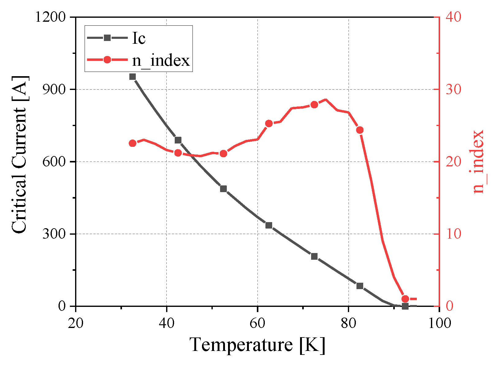
2.1. The Flow Capacity of HTS Tapes under Different Temperatures
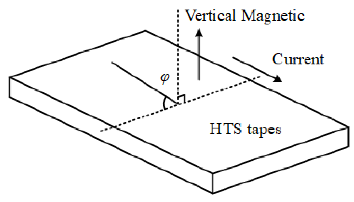
2.2. Anisotropy of Superconducting Tapes
3. Preliminary Design of HTS Cable
3.1. The Parameters of 4 kA HTS Cable
- (1)
- Superconducting cable operating temperature range
- (2)
- Number of tapes
- (3)
- Number of conductor layers
- (4)
- Electrical insulation design
- (5)
- Cable cross-sectional area
3.2. 4 kA HTS Cable Design
- (1)
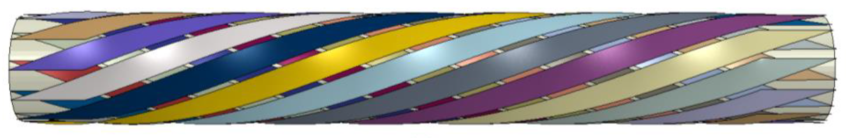
- CORC
- (2)
- Roebel
- (3)
- TSTC
- (4)
- Quasi-isotropic HTS strands
- (5)
- CICC
4. Optimum Design of Cable Conductor Layout
4.1. Evaluation Index of Cable Performance
- (1)
- Average external magnetic field Bavg_out
- (2)
- External magnetic field uniformity Bdel_out
- (3)
- Maximum magnetic field Bmax
- (4)
- Engineering critical current Ic
- (5)
- Spatial-quantity ratio S/N
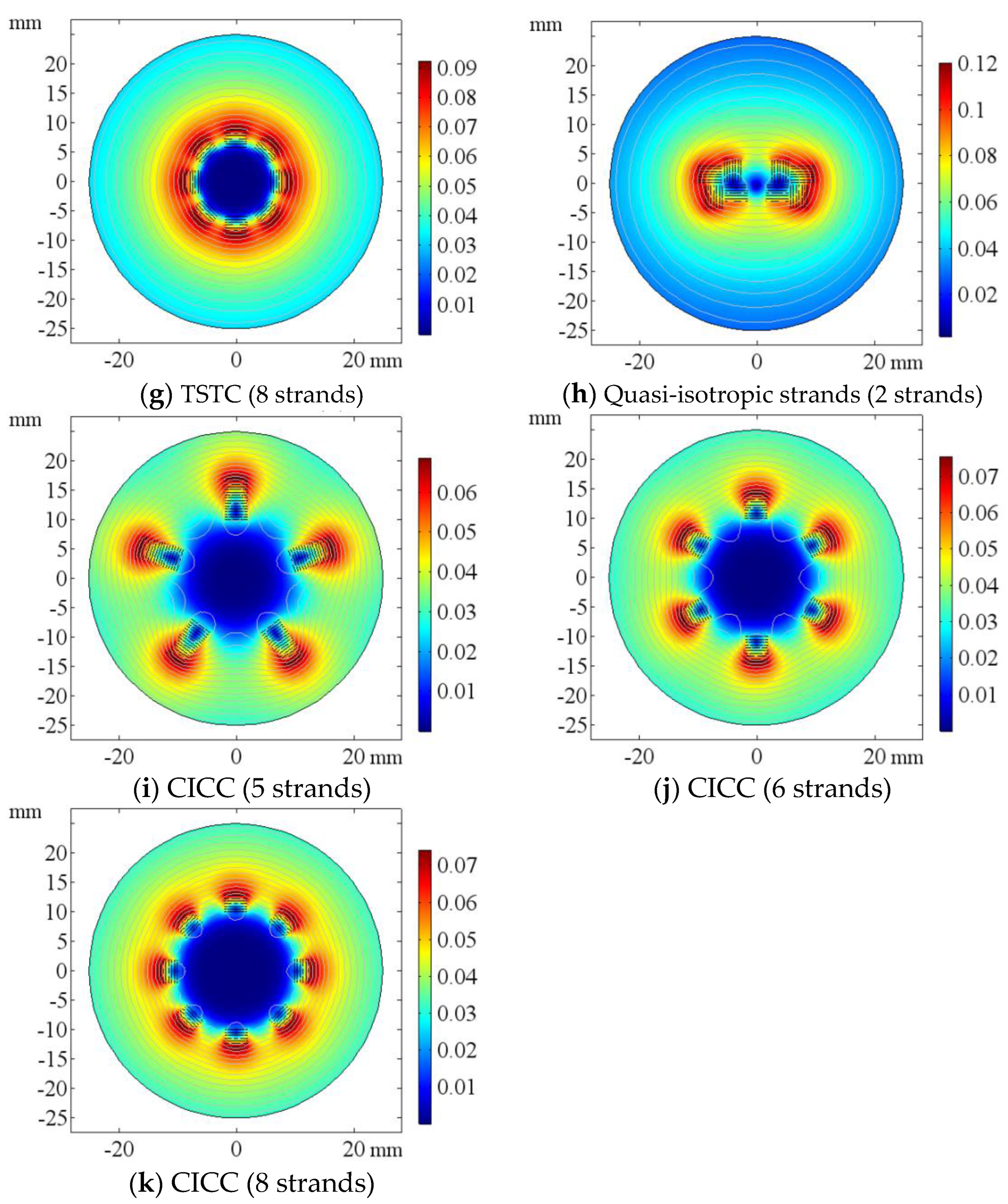
4.2. Performance Analysis of Different Conductor Layouts
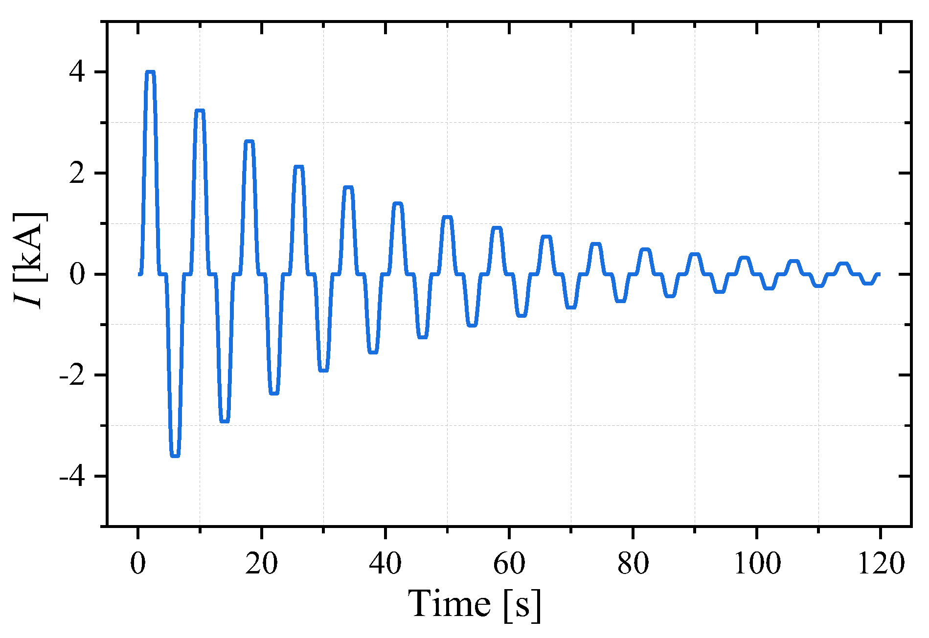
5. AC Loss Calculation
5.1. Simulation Method Validation
5.2. AC Loss Calculation for 60 K CORC Cable
6. Conclusions
- The characteristics of superconducting tapes were summarized: the lower the temperature and the smaller the magnetic field, the stronger the current-carrying capacity of the tape; under the same magnetic field, the critical current attenuation of the superconducting tape caused by the vertical magnetic field is significantly greater than that of the parallel magnetic field.
- The parameters of HTS cables were determined first. The working temperature of the cable was selected to be 60 K, gaseous helium was used as the refrigerant and the number of tapes was at least 22. Superconducting cable conductors are laid out in multiple layers. The cable uses polyimide as the insulating material and is wrapped in a single layer with a thickness of 0.1 mm. The influence of rated voltage and cable length on the energized cross-section does not need to be considered. Then, the cable conductor layout methods of CORC, Roebel Cable, TSTC, CICC and quasi-isotropic structures were designed and finite element models under different layouts were built.
- The average external magnetic field, the external magnetic field uniformity, the maximum magnetic field, the engineering critical current and the space quantity ratio were selected as the cable performance evaluation index indexes. The performance of different layouts was analyzed and CORC structure has advantages over other structures in terms of the maximum magnetic field and critical current attenuation inside the cable. Therefore, the CORC structure was selected.
- The simulation model of superconducting cable was built based on T-A method and the AC loss of 60 K CORC cable was calculated. The cooling system can ensure the safe operation of the cable in the rated temperature range.
Author Contributions
Funding
Data Availability Statement
Conflicts of Interest
References
- Kottonau, D.; de Sousa, W.T.B.; Bock, J.; Noe, M. Design Comparisons of Concentric Three-Phase HTS Cables. IEEE Trans. Appl. Supercond. 2019, 29, 5401508. [Google Scholar] [CrossRef]
- Fetisov, S.S.; Zubko, V.V.; Zanegin, S.Y.; Nosov, A.A.; Ryabov, S.M.; Vysotsky, V.S. Study of the First Russian Triaxial HTS Cable Prototypes. IEEE Trans. Appl. Supercond. 2017, 27, 5400305. [Google Scholar] [CrossRef]
- Angeli, G.; Bocchi, M.; Ascade, M.; Rossi, V.; Valzasina, A.; Martini, L. Development of Superconducting Devices for Power Grids in Italy: Update About the SFCL Project and Launching of the Research Activity on HTS Cables. IEEE Trans. Appl. Supercond. 2017, 27, 5600406. [Google Scholar] [CrossRef]
- Lee, S.-J.; Sung, H.-J.; Park, M.; Won, D.; Yoo, J.; Yang, H.S. Analysis of the Temperature Characteristics of Three-Phase Coaxial Superconducting Power Cable according to a Liquid Nitrogen Circulation Method for Real-Grid Application in Korea. Energies 2019, 12, 1740. [Google Scholar] [CrossRef]
- Nguyen, T.-T.; Lee, W.-G.; Lee, S.-J.; Park, M.; Kim, H.-M.; Won, D.; Yoo, J.; Yang, H.S. A Simplified Model of Coaxial, Multilayer High-Temperature Superconducting Power Cables with Cu Formers for Transient Studies. Energies 2019, 12, 1514. [Google Scholar] [CrossRef]
- Nguyen, T.-T.; Lee, W.-G.; Kim, H.-M.; Yang, H.S. Fault Analysis and Design of a Protection System for a Mesh Power System with a Co-Axial HTS Power Cable. Energies 2020, 13, 220. [Google Scholar] [CrossRef]
- Lee, S.-J.; Kang, S.Y.; Park, M.; Won, D.; Yoo, J.; Yang, H.S. Performance Analysis of Real-Scale 23 kV/60 MVA Class Tri-Axial HTS Power Cable for Real-Grid Application in Korea. Energies 2020, 13, 2053. [Google Scholar] [CrossRef]
- Choi, Y.; Kim, D.; Lee, C.; Won, D.; Yoo, J.; Yang, H.; Kim, S. Thermo-Hydraulic Analysis of a Tri-Axial High-Temperature Superconducting Power Cable with Respect to Installation Site Geography. Energies 2020, 13, 3898. [Google Scholar] [CrossRef]
- Huang, Z.; Wang, Y.; Lu, X.; Zhang, X.; Li, G.; Wang, L. A Multilayer Three-Phase Coaxial HTS Cable With Large Capacity and Low Loss. IEEE Trans. Appl. Supercond. 2022, 32, 4803007. [Google Scholar] [CrossRef]
- Inoue, R.; Ueda, H.; Kim, S. Basic Study on Power Transmission Characteristics for High-Temperature Superconducting Cable Termination Applying a Wireless Power Transmission System. IEEE Trans. Appl. Supercond. 2022, 32, 5400804. [Google Scholar] [CrossRef]
- Sadeghi, A.; Seyyedbarzegar, S.; Yazdani-Asrami, M. Investigation on the Electrothermal Performance of a High Temperature Superconducting Cable in an Offshore Wind Farm Integrated Power System: Fault and Islanding Conditions. IEEE Trans. Appl. Supercond. 2022, 32, 5401011. [Google Scholar] [CrossRef]
- Oh, D.K. An Alternative in H-Formulation to the Critical Current Model of HTS Conductors. IEEE Trans. Appl. Supercond. 2022, 32, 4901808. [Google Scholar] [CrossRef]
- Jacob, T.; Buchholz, A.; Noe, M.; Weil, M. Comparative Life Cycle Assessment of Different Cooling Systems for High-Temperature Superconducting Power Cables. IEEE Trans. Appl. Supercond. 2022, 32, 4802805. [Google Scholar] [CrossRef]
- Tang, T.; Zong, X.H.; Yu, Z.G.; Lu, X.H.; Han, Y.W. Design and operation of cryogenic system for 35kV/2000A HTS power cables. In Proceedings of the 2015 IEEE International Conference on Applied Superconductivity and Electromagnetic Devices (ASEMD), Shanghai, China, 20–23 November 2015; pp. 573–575. [Google Scholar] [CrossRef]
- HTS Wire Critical Current Database. Available online: https://htsdb.wimbush.eu/ (accessed on 1 November 2021).
- Rossi, L.; Hu, X.; Kametani, F.; Abraimov, D.; Polyanskii, A.; Jaroszynski, J.; Larbalestier, D.C. Sample and length-dependent variability of 77 and 4.2 K properties in nominally identical RE123 coated conductors. Supercond. Sci. Technol. 2016, 29, 054006. [Google Scholar] [CrossRef]
- Kubiczek, K.; Grilli, F.; Kario, A.; Godfrin, A.; Zermeno, V.; Stepien, M.; Kampik, M. Length Uniformity of the Angular Dependences of Ic and n of Commercial REBCO Tapes with Artificial Pinning at 77 K. IEEE Trans. Appl. Supercond. 2019, 29, 8000309. [Google Scholar] [CrossRef]
- Zhang, H.; Zhu, J.; Xu, W.; Zhu, C.; Zhang, H.; Deng, X. Design of three-phase coaxial cold insulated superconducting cable. Cryog. Supercond. 2019, 47, 10. [Google Scholar]
- Van der Laan, D.C. YBa2Cu3O7−delta coated conductor cabling for low ac-loss and High-field magnet applications. Supercond. Sci. Technol. 2009, 22, 065013. [Google Scholar] [CrossRef]
- Zhang, M.; Coombs, T.A. 3D modeling of high-Tc superconductors by finite element software. Supercond. Sci. Technol. 2011, 25, 015009. [Google Scholar] [CrossRef]
- Sheng, J.; Vojenčiak, M.; Terzioglu, R.; Frolek, L.; Gömöry, F. Numerical study on magnetization characteristics of superconducting conductor on round core cables. IEEE Trans. Appl. Supercond. 2016, 27, 4800305. [Google Scholar] [CrossRef]
- Terzioğlu, R.; Vojenčiak, M.; Sheng, J.; Gömöry, F.; Çavuş, T.F.; Belenli, İ. AC loss characteristics of CORC cable with a Cu former. Supercond. Sci. Technol. 2017, 30, 085012. [Google Scholar] [CrossRef]
- Zhang, H.; Zhang, M.; Yuan, W. An efficient 3D finite element method model based on the T–A formulation for superconducting coated conductors. Supercond. Sci. Technol. 2016, 30, 024005. [Google Scholar] [CrossRef]
- Wang, Y.; Zhang, M.; Grilli, F.; Zhu, Z.; Yuan, W. Study of the magnetization loss of CORC cables using a 3D TA formulation. Supercond. Sci. Technol. 2019, 32, 025003. [Google Scholar] [CrossRef]
- Zermeño, V.M.R.; Habelok, K.; Stępień, M.; Grilli, F. A parameter-free method to extract the superconductor’s Jc(B,θ) field-dependence from in-field current–voltage characteristics of high temperature superconductor tapes. Supercond. Sci. Technol. 2017, 30, 034001. [Google Scholar] [CrossRef]
- COMSOL Inc. Available online: https://cn.comsol.com/ (accessed on 1 February 2022).
- Zhu, K.; Guo, S.; Ren, L.; Xu, Y.; Wang, F.; Yan, S.; Liang, S.; Tang, Y.; Shi, J.; Li, J. AC loss measurement of HTS coil under periodic current. Phys. C Supercond. Its Appl. 2020, 569, 1353562. [Google Scholar] [CrossRef]


| Label | Number of Strands | Number of Tapes per Strand | Number of Tapes | Size of Each Strand |
|---|---|---|---|---|
| TSTC-2 | 2 | 11 | 22 | Φ 4.04 |
| TSTC-3 | 3 | 7 | 21 | Φ 4.11 |
| TSTC-4 | 4 | 6 | 24 | Φ 4.21 |
| Structure | Bavg_out (mT) | Bdel_out (mT) | Bmax (mT) | Ic (A) | S/N |
|---|---|---|---|---|---|
| CORC (2 layers) | 32.054 | 0.471 | 38.856 | 115.81 | 26.66 |
| CORC (3 layers) | 32.095 | 0.705 | 54.852 | 107.39 | 13.242 |
| TSTC (3 strands) | 32.097 | 2.354 | 117.08 | 89.64 | 5.5779 |
| TSTC (4 strands) | 32.102 | 1.834 | 120.81 | 89.33 | 4.377 |
| TSTC (5 strands) | 32.102 | 0.473 | 123.54 | 89.24 | 3.4448 |
| TSTC (6 strands) | 32.101 | 0.553 | 109.53 | 90.01 | 3.9569 |
| TSTC (8 strands) | 32.103 | 0.447 | 101.62 | 93.58 | 4.5329 |
| CICC (5 strands) | 32.126 | 7.406 | 76.621 | 100.33 | 16.834 |
| CICC (6 strands) | 32.124 | 1.914 | 83.345 | 96.62 | 10.812 |
| CICC (8 strands) | 32.111 | 0.368 | 83.079 | 98.25 | 9.4444 |
| Quasi-isotropic (2 strands) | 32.098 | 6.7 | 122.93 | 88.96 | 5.9401 |
Publisher’s Note: MDPI stays neutral with regard to jurisdictional claims in published maps and institutional affiliations. |
© 2022 by the authors. Licensee MDPI, Basel, Switzerland. This article is an open access article distributed under the terms and conditions of the Creative Commons Attribution (CC BY) license (https://creativecommons.org/licenses/by/4.0/).
Share and Cite
Peng, S.; Cai, C.; Cai, J.; Zheng, J.; Zhou, D. Optimum Design and Performance Analysis of Superconducting Cable with Different Conductor Layout. Energies 2022, 15, 8893. https://doi.org/10.3390/en15238893
Peng S, Cai C, Cai J, Zheng J, Zhou D. Optimum Design and Performance Analysis of Superconducting Cable with Different Conductor Layout. Energies. 2022; 15(23):8893. https://doi.org/10.3390/en15238893
Chicago/Turabian StylePeng, Sisi, Chuanbing Cai, Jiaqi Cai, Jun Zheng, and Difan Zhou. 2022. "Optimum Design and Performance Analysis of Superconducting Cable with Different Conductor Layout" Energies 15, no. 23: 8893. https://doi.org/10.3390/en15238893
APA StylePeng, S., Cai, C., Cai, J., Zheng, J., & Zhou, D. (2022). Optimum Design and Performance Analysis of Superconducting Cable with Different Conductor Layout. Energies, 15(23), 8893. https://doi.org/10.3390/en15238893