Article

A FEM-Based Comparative Study of the Effect of Rotor Bar Designs on the Performance of Squirrel Cage Induction Motors

Department of Electrical and Electronics Engineering, Faculty of Technology, Gazi University, Ankara 06560, Turkey
Energies 2023, 16(16), 6047; https://doi.org/10.3390/en16166047
Submission received: 20 July 2023 / Revised: 14 August 2023 / Accepted: 15 August 2023 / Published: 18 August 2023

Abstract

:
Induction motors (IM) are the most frequently used type of motor in the industry. The number of rotor slots, bar geometry, and conductivity of bar material have a strong impact on the torque profile and efficiency characteristics of induction motors. This study focused on investigating the effect of different rotor bar designs on motor performance by the finite element method (FEM). The IMs have been designed using the same stator core, winding, and core lengths. The total rotor bar cross-section areas are also fixed throughout all designs. In addition to the change in the number of rotor bars and geometry, the effect of copper and aluminum bar materials on motor performance was also investigated, both for single and double-layered squirrel-cage structures. The results of the study indicate that the starting torque of the motor in a 36/30-slot aluminum single-cage structure was obtained as 96.26 Nm, while the starting torque of a 36/46-slot aluminum double-cage structure was found to be 115.34 Nm. It is also found that the starting torque of the initial design can be increased by up to 19.82% by changing only the rotor bar numbers and material with the same stator and rotor size. The efficiency of the motors was determined as 86.6% for both designs. In addition to efficiency, the output torque ripple has been decreased to 2.63, which equals a 67.32% decrease in the ripple of the initial design. The improved design has an approximately 8 °C lower T2 due to better cooling performance as a result of a higher number of rotor slots.

1. Introduction

With the growth of the world population, energy consumption has increased, resulting in a reduction in the limited amount of fossil fuel reserves. Recently, with the impending depletion of petroleum resources, numerous researches have been focused on alternative drive systems in the industry that apply to vehicles, trains, ships, and planes [1,2,3].
Electric motors are among the most important elements of today’s modern drive systems. Different types of motors are used in the industry. Mostly induction motors (IMs), permanent magnet synchronous motors (PMSM), and DC motors are preferred due to several advantages according to the application where they are intended to be used [4,5]. Improvements in magnet technology have led to increased efficiency in permanent magnet (PM) motors. However, high prices of rare earth materials and demagnetization issues are still disadvantages of PM motors [6]. Although DC motors have a linear speed-torque curve, the fact that they have a commutator and brushed structure limits their use [7]. In SRMs, the fluctuations in the output torque and the low torque density value restrict the use of this machine type in applications that require a high power-to-weight ratio [8]. Due to their low maintenance requirements, easy controllability, high temperature tolerance, easy production, and low costs, IMs are among the most preferred motors in the industry [9,10,11,12]. Traction applications are good examples where the output torque capability of the motor is crucial, as well as constant power, constant torque, and variable power applications in the industry. In the work of Xue et al., in order to determine the most suitable electric motor, five types of electric machines were compared (IMs, SRMs, brushless DC motors, brushed DC motors, and SMs) and examined in terms of efficiency, weight, cost, cooling, maximum speed, fault tolerance, safety, and durability. As a result of the analyses, the SRM, followed by the IM, was determined to be suitable for use in traction applications in terms of efficiency, weight, and cost [13]. Guzinski et al. used a squirrel-cage induction motor driven by DC voltage in the system. They determined that the use of the squirrel-cage induction motor was more advantageous in EVs than the other electric motors [14]. Permanent magnet machines are preferred as traction motors because of their high efficiency and power density. However, the high costs and supply problems of the rare earth magnets used in these motors led automotive manufacturers to search for alternatives. It is also possible to attain high efficiency using a purpose-designed induction motor.
Kim et al. achieved starting and operating point characteristics by optimizing the air gap and the geometry of the rotor bars in an induction motor [15]. In one study investigating the rotor slot structures, the air gap reluctance was reduced by adding wedges to the upper part of the slot of the induction motor using a semi-closed slot structure. Thus, stator current and core losses were reduced. In addition, the vibration level of the machine decreased [16]. In another structural analysis study, the performance of double- and single-cage induction motors was investigated. Accordingly, it was determined that the double-cage structure had a low starting current. With the low current, the copper loss was reduced, and the efficiency of the motor increased [17]. When the effect of the rotor slot structure on current harmonics was examined, it was found that 5th and 7th harmonics are much higher in open-slot induction motors than in closed rotor slot structures [18]. In a study where different numbers of slots were investigated, the number of rotor slots was determined as 24, 28, 30, 40, 41, and 48, and the performance of the induction motor was analyzed. The efficiency was the best in the 28-slot structure, but it had a low power coefficient. The highest power coefficient was in the 40-slot structure, but the efficiency was low. The 41-slot structure was found to give a relatively average performance compared to the others, whereas the rotor with 48 slots achieved the highest torque and power [19], and a geometry-based optimization study of an induction motor is given in [20]. The effect of the combination of pole/slot numbers on motor performance has also been investigated in the literature. The lowest rotor loss and the highest efficiency are achieved with a combination of 20 poles and 30 slots, while the highest power density is achieved with a structure of 24 poles and 27 slots [21].
For the literature studies given above, slot geometry was optimized through a single structure, the geometric structure of the rotor bars or the rotor slot structure was examined, and the effect of the stator geometries was evaluated. In addition, machine designs were created taking into account either the geometric structure of the squirrel cage or the effect of material differences. In another study that examines the rotor slot geometry, the effect of eight different bar structures was investigated in a 4-pole squirrel-cage machine. It was determined that the rectangular and fluted shapes provide low rotor loss [22]. The rotor slot number and rotor conductor type, as well as the single- or double-cage structure, have a significant effect on the torque-speed curve and efficiency of the motor [23,24]. In the investigation of the effect of slot numbers, it has been determined that the prototype with a higher number of slots in a permanent magnet synchronous machine yields the best results in terms of efficiency and torque ripple at nominal load [25].
Due to their complex structure and nonlinear mathematical models, the optimal design of electrical machines often necessitates the simultaneous use of various optimization techniques alongside computer-aided design software. In recent years, particularly, there has been a notable focus on multi-objective optimization, which involves optimizing the machine with regard to multiple objective functions. NSGA-II (non-dominated sorting genetic algorithm II) [26,27,28], OBJSO (opposition-based jellyfish search optimization), which is also compared to GA (genetic algorithm), PSO (particle swarm optimization), and JSO (jellyfish search optimization) [29], combined PS (pattern search), GA, and ES (evolution strategy) [30], and PSO-based optimal design studies [31,32] have been employed in the multi-objective optimization of different machines, resulting in a substantial enhancement in the optimized motor’s performance.
Conversely, permanent magnet motors offer higher efficiency in a much wider speed range compared to induction motors. This efficiency provides an important advantage in applications with a wide speed range, such as electric cars. For this reason, PM motors are preferred in almost all of today’s electric cars. There is a negligible efficiency difference between PM motors and induction motors, especially when operating in a highway cycle [33].
The effects of rotor resistance and reactance on the torque profile of the induction motor are well known. However, keeping the same rotor resistance for different bar numbers and geometry results in different torque profiles due to other effects, such as rotor reactance. A 7.5 kW, 2-pole induction motor was designed to obtain comparative results based on the rotor slot number, geometry, and bar material. The study has focused on the investigation of the effect of the number of stator/rotor slots on motor torque and performance by keeping the total rotor bar cross-section area constant. In addition to changes in rotor slot geometry, the effect of copper and aluminum cage materials on motor performance was also determined using single- and double-layered squirrel-cage structures with different stator/rotor slot combinations. The main contributions of the study are listed below:
  • The effect of single-cage and double-cage rotor structures in different slot combinations on the induction motor has been examined;
  • The effects of aluminum and copper cage structures on various slot number combinations in the induction motor have been compared;
  • The impact of different rotor slot numbers on motor performance has been analyzed while keeping the same stator;
  • Changes in starting torque due to both cage material and rotor slot number and structure have been obtained;
  • The effects of different slot combinations on the output torque have been compared using FEM;
  • Output torque ripple values obtained from different slot combinations have been obtained and compared;
  • While the effects of single-cage and double-cage slot structures are well known, the changes that may arise from different slot number combinations and different cage materials have been comprehensively presented.
This work deals with the influence of several rotor slot numbers, both for Cu and Al conductors, on the behavior of the induction motor. Firstly, different stator-rotor slot combinations and a single-cage structure were compared with a double-cage rotor structure for each combination. The effect of the aluminum and copper materials on the total performance of the motor was then investigated for the squirrel cage. The rest of the article is organized as follows: In Section 2, general design considerations and the NEMA class of the machine are discussed. General design parameters and a 3D model of the initial design are given in Section 3. The detailed effects of rotor slot number, structure, and material on the performance of the induction motor and a comparison of single- and double-cage rotor designs are presented, and the transient electromagnetics and thermal performances of the motors with the initial and improved designs have been compared in Section 4 and Section 5, respectively. Finally, Section 6 is reserved for the evaluation of the results and the conclusions.

2. Design Considerations

The torque characteristics of induction motors are grouped into five different design classes (A, B, C, D, and E) by the National Electrical Manufacturers Association (NEMA). In this classification, there are various extreme examples, such as Class D motors with high starting torque, high slip, and low efficiency, and Class E with high efficiency and low starting torque at minimum slip. Therefore, the selection of an induction motor type suitable for the operating characteristics of the load is vital in terms of system efficiency and meeting the expected performance.
It is essential to consider the above-mentioned criteria in the design of a mains-fed induction motor. An induction motor with high efficiency and high starting torque is desirable for all applications. One of the most important features expected from the motor that drives heavy loads is high starting torque capability. However, considering the different design classes mentioned above, there is no motor class with a squirrel cage that provides the highest starting torque and highest efficiency at the same time. However, IEC 60034-30-1: 2014 specifies efficiency classes for single-speed electric motors for operation on a sinusoidal voltage supply [34]. The standard defines four IE (international efficiency) efficiency classes as standard (IE1), high (IE2), premium (IE3), and super-premium (IE4). A comparative study of induction motors of IE2, IE3, and IE4 efficiency classes for pump applications is given in [35]. The study is a good example of the amount of reduction in CO2 emissions and energy savings between IE1 and IE4. On the other hand, in terms of motor design and characteristics, moving from IE1 to IE4 results in an increase in starting current and a decrease in locked rotor torque, which are critical parameters for loads that have heavy starting conditions other than pump applications. This is because motor impedance is changed in order to curtail losses [36,37,38,39]. As the main purpose of this study is to determine the difference between various designs, especially starting behavior and torque profile, an IE1 class motor is selected for case studies. However, improvements and differences between design variations are also valid for IE2, IE3, and IE4 designs, which basically have an increasing amount of active material, respectively.
The nominal efficiency is low in designs that can provide very high starting torque, and the starting torque is low in designs that provide very high nominal efficiency. In this case, the motor characteristics should offer the highest values for both starting torque and nominal efficiency. When the classification details are considered, the design that provides the closest values to this expectation is called Class B. In addition, NEMA Class B is the most common induction motor class in use for both industrial and traction applications [40,41,42,43].
As seen in Figure 1, there is no fixed slot geometry in Class B designs; however, basically, it is possible to see them divided into single- and double-cage designs. A double-cage design is not needed for a variable frequency driven (VFD) motor, but in terms of mains operation, it is the most preferred one, especially for high nominal power ranges. Also, general-purpose motor manufacturers mostly have double-cage rotor slot designs, but designers may use this type of slot geometry to avoid a new slot mold. There are few studies in the literature covering the effects of rotor slot geometry and bar material on the NEMA B-type induction machine’s performance under the constant rotor resistance scenario.
In line with the above-mentioned information, when examining the heavy-duty motors of top manufacturers, even though a significant number of them have a single-cage copper rotor, it is known that some manufacturers, such as ABB [44], prefer an aluminum cage in traction motors.
With the advances in magnet technology in recent years, there has been an increase in the energy density of PM machines. Therefore, higher power density and efficiency within a wide speed range can be obtained in such machines. However, a purpose-designed induction motor is more reliable and robust than a machine with permanent magnets. Induction motors have high-temperature resistance. In addition, compared to PM machines, they can maintain their nominal performance throughout their lifetime with almost no reduction. In extreme applications like EVs, which require both city and highway driving cycles, thanks to their unique properties, such as maximum operational speed, induction machines are still the preferred motor type. In addition, as a result of the experience obtained with long-term testing, leading manufacturers in the market have increasingly expressed interest in these motors [45,46].

3. Initial Model and Specifications of Proposed IM

The design of electric machines can start with output equations. The relationship between machine output, core sizes, speed, and specific magnetic and electrical loading are expressed as output equations. Power developed on the armature side, based on a machine with an m phase, is calculated using Equation (1) [47].
Q = 3 × V p h I p h × 10 3
where the variable, Q , is the rating of the machine in kVA, and I p h and V p h represent the phase current and the induced emf on the armature, which is derived from Equation (2) [47].
V p h = 4.44 × k w × f × 1 × N p h
here, 1 is the fundamental flux per pole, N p h is the number of turns per phase, f refers to the frequency, and k w is the winding factor (equal to 0.955). The total specific electrical loading is given in Equation (3) [47].
a c = I z Z π D
In Equation (3), D is the armature diameter, I z is current, Z is the total number of the armature or stator conductors, and the product of these two terms is called total electrical loading. Specific magnetic loading is found using Equation (4) [47,48]:
B o r t = p π D L
where L is the stator core length, p is the pole number, and is the magnetic flux per pole. Considering Equations (2)–(4), the output equation is rewritten as Equation (5) [47,48]:
Q = 1.11 π 2 B a v a c K w × 10 3 D 2 L n s
where n s is the synchronous speed and C 0 is known as the output coefficient and expressed as in Equation (6) [47,48].
C 0 = 11.1 × B a v × a c × 10 3
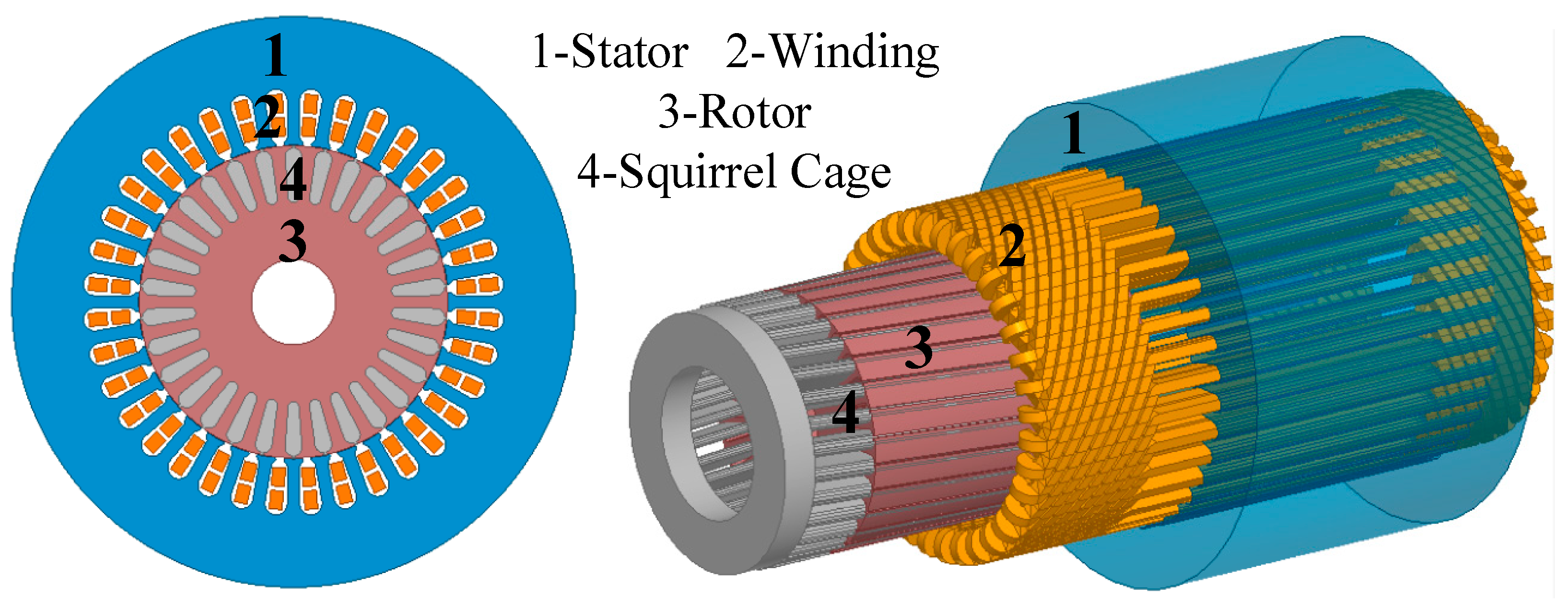
The designs and analyses of the initial 2D and 3D models of the three-phase, 7.5 kW, 400 V, 2-pole induction motor were completed. Figure 2 presents the initial designs of these models. All parameters of the motor design were calculated using an analytical method and are given in Table 1.

4. Comparison of Single and Double-Cage Rotor Designs

Many parameters affect the performance of electrical machines. The design and performance assessment of electrical machines requires the integration of multiple disciplines. The use of computer-aided methods such as finite element and finite difference techniques is essential for analyzing electrical machines, enabling the creation of the desired design and behavioral model of the machine. FEM is successfully employed for the approximate solution of problems expressible through differential equations. In this method, the region under investigation is divided into a finite number of elements, commonly referred to as a mesh. These elements surrounding the chosen region are interconnected in a chained manner, forming nodes. The solution of these nodes allows the calculation of parameters such as current, voltage, torque, and magnetic flux density [49].
In induction machines, since the number and structure of the slots change the magnetic circuit of the machine, they also affect its electrical performance [40,50]. The number of stator slots should be an integer and allow for a balanced winding. In addition, the number of stator slots should be an exact multiple of the phase number. In this study, considering these criteria, the number of stator slots was determined to be 36 by considering the reference motor manufacturers. The common number of slots used in low-power 3-phase machines is 36. The determining factor in the number of slots is the number of poles. Considering harmonics, the slots per pole per phase must be at least two or more. Selecting a large value will cause the number of slots to increase, resulting in additional costs. The balance between harmonics and cost is achieved in a 2-pole low-power motor using 24 or 36 slots. The number of rotor slots should not be equal to the number of stator slots and should not be half or twice the number of stator slots [51,52]. In the study, the number of stator slots was taken as a constant in order to make the comparison more equitable.
This section discusses the investigation of the effect of the induction motor rotor slot number (26, 28, 30, 34, 44, and 46), structure (single- and double-cage), and squirrel-cage material (copper and aluminum) on the efficiency, rated torque, total weight, and starting torque.

4.1. Single-Cage Rotor with Different Numbers of Slots

In this section, the performance effects of different numbers of rotor slots for the single-cage rotor are compared. The number of rotor slots specified for comparison includes the most common number of rotor slots used by different manufacturers in the industry. In order to ensure a fair comparison, except for the rotor slots, no changes were made to the motor geometry in any of the designs.
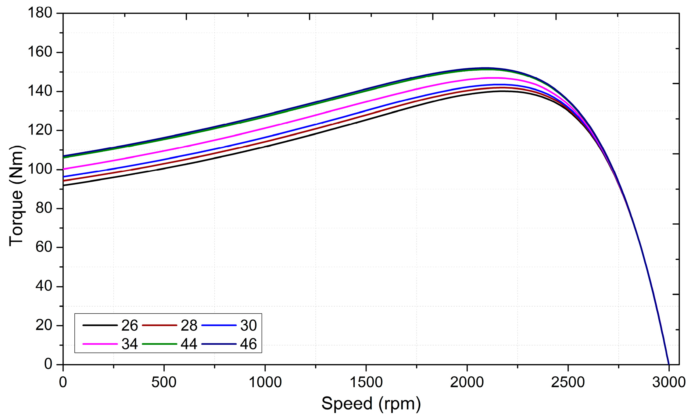
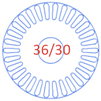
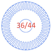
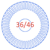
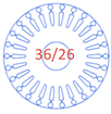
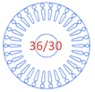
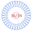
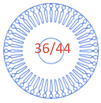
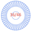
In Table 2, the results of the analysis of the motors with different numbers of rotor slots are summarized. When Table 2 is examined, it can be seen that the efficiency values of the different rotor combinations remained approximately the same. In order to obtain similar flux values in rotor slots, slots were narrowed in motors with rotor slot numbers 34, 44, and 46. The speed-torque curves obtained according to the changing number of slots are given in Figure 3.
As can be seen from Figure 3, in the 36/26 configuration, the starting torque was 91.89 Nm, whereas in the 36/46 configuration, this value increased to 106.83 Nm. An approximately 16% difference can be achieved even between single-cage designs. At the same time, each design has approximately the same active weight and efficiency. The waveforms and ripple values of the output torques for single-cage designs were obtained using Ansys Maxwell 2D v16 and are comparatively presented in Figure 4. Among all the designs, the 36/46-slot combination design provides the lowest ripple value, while the 36/34-slot combination design yields the highest torque ripple value. In fact, the 36/34 combination is among the combinations that should be avoided [42], and it has been included in this study for comparison with other combinations. Therefore, a detailed FEM analysis is required to investigate the effects of these combinations on the output torque.

4.2. Double-Cage Rotor with Different Numbers of Slots

This section examines the effects of different numbers of rotor slots on motor performance. However, this time the rotor slots are designed as a double cage. Except for rotor slot geometries, no changes were made in the stator slots, inner and outer diameters, or stack length of the motor. Rotor slot geometries were created to provide the best performance for each different number of rotor slots. Table 3 summarizes the motor structures and the results of the analysis.
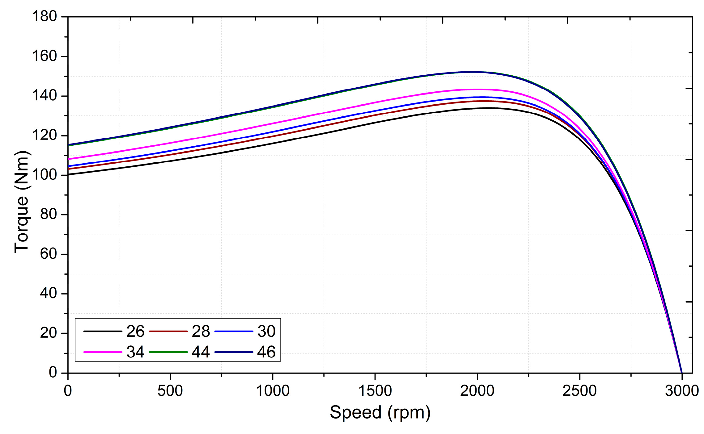
As in the single-cage rotor, the efficiency values of the motors remained approximately the same due to the fixed stator structure. In order to obtain similar flux values in the rotor slots, slots were narrowed in motors with 34, 44, and 46 rotor slots. The torque changes obtained according to the changing number of slots are given in Figure 5.
Figure 5 shows that, in the 36/26 configuration, the starting torque was 100.33 Nm, while the highest value was achieved in the 36/46 configuration at 115.35 Nm. A significant difference of approximately 15% can be achieved between the starting torque provided by the double-cage designs as in the single cage. All designs have equal rotor slot depth and are suitable for the NEMA B class. The combination of the 36/46 offers the best efficiency/cost ratio per unit of torque production. Torque waveforms and ripples of double-cage designs obtained by 2D transient FEM simulation are given in Figure 6. The range of 80–120 ms, where the output torque stabilizes, has been considered in the graph. Similar to the single-cage designs, the design with a 36/46-slot combination provides the lowest ripple value among other combinations, while the design with a 36/34-slot combination yields the highest torque ripple value. As previously mentioned, the unsuitability of the 36/34 combination, valid for both single and double-cage designs, is further confirmed by these analyses.

4.3. Effect of Rotor Cage Material with Different Combinations

Another important design parameter for squirrel-cage induction motors is the cage material. The resistance of the rotor cage material is directly related to motor performance. As easily predicted, higher rotor resistance means higher starting torque. The effect of using copper or aluminum as a cage material for the same rotor slot cross-sectional area is a well-known subject in the literature studies. However, the aim of this section of the study was to reveal the differences between each of the slot combinations and Al or Cu cage materials. Thus, a machine designer can easily switch to his own preferred combination using the variety of scenarios in this section [53,54]. The conductivity of copper is 60% higher than that of aluminum. However, its high melting point in the squirrel-cage production stage may damage the steel sheet used in the rotor [52,55,56].
The use of copper is also disadvantageous in terms of cost and ease of production. In the study, the conductivity and mass density value of the copper material used is 58 × 106 S/m and 2700 kg/m3, while the conductivity and mass density value of the aluminum material used is 33 × 106 S/m and 8933 kg/m3. The performance of the 36/46-slot motors with single- and double-cage rotors made of copper and aluminum squirrel cages is presented in Table 4. In the analyses, the geometry of the rotor was kept constant, and only the effect of the cage material was examined.
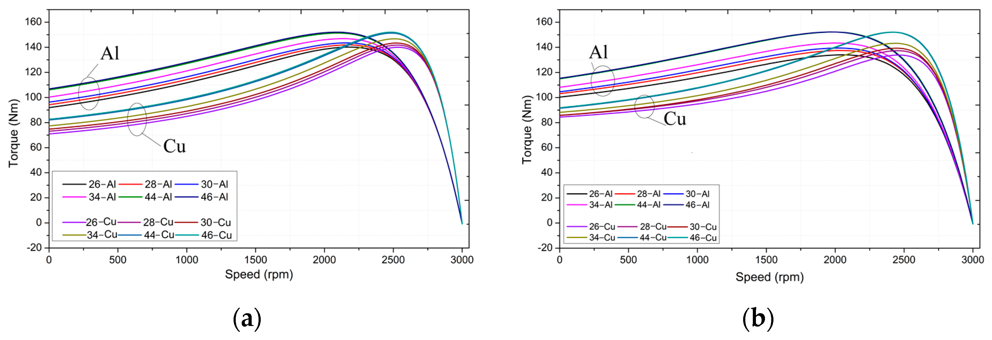
As expected, the rotor resistance of motors with an aluminum cage was higher than those with a copper cage. Consequently, rotor copper losses were higher, and their efficiency was low. However, high rotor resistance allowed a high starting torque. In this case, the highest starting torque value was obtained in the motor having the aluminum double-cage rotor with the 36/46 structure. As expected, using both a double cage and Al material led to this result.
However, high rotor resistance allowed a high starting torque. In this case, the highest starting torque value was obtained in the motor having the aluminum double-cage rotor with the 36/46 structure. As expected, using both a double cage and Al material led to this result. More importantly, the difference between copper and aluminum cages for each combination can be seen in the torque-speed curves shown in Figure 7.

5. Performance Comparison of the Designs

As it can be understood from Table 4, the single-cage 36/46-slot combination provides higher efficiency than all other combinations, whether using Cu or Al material rotor conductors. Also, considering the 36/46 combination, there is an acceptable difference (106 vs. 115 Nm) between the maximum starting torques produced by double-cage and single-cage structures. For LEV-class applications, the single cage is an efficient model in the manner of considering the material of not only the Cu cage but also the Al cage. For this reason, it should be considered to use a single-cage structure. The total weights of the single-cage and double-cage combinations are approximately equal to each other. In this respect, it should be taken into consideration that similar costs will be incurred.
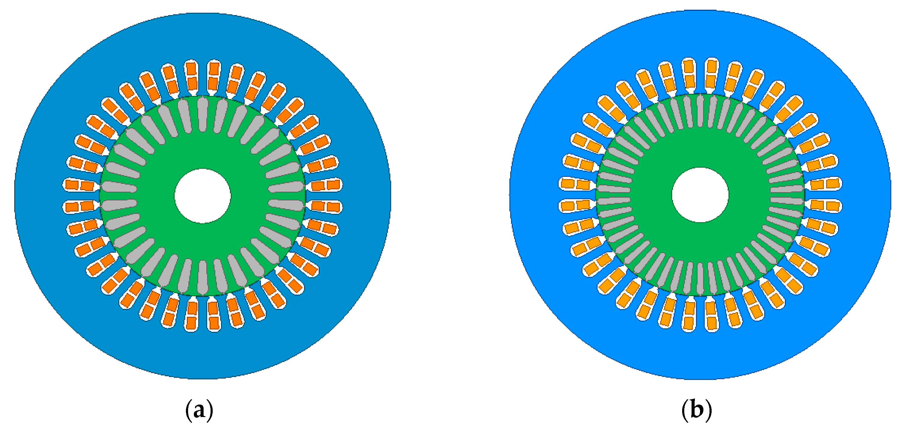
In this section, the transient and magnetostatic performances of the motors with the initial and improved designs have been compared via Ansys Maxwell. In addition to the electromagnetic performance calculations, steady-state and transient thermal analyses have been conducted to verify the designs’ appropriateness. The initially designed motor is a 36/30 aluminum and single-cage structure. From the simulation results, it is seen that the 36/46 aluminum cage structure has almost the same starting torque as the double cage one but has better efficiency. So, the 36/46 aluminum single-cage design will hereafter be referred to as an improved design. The 2D models of the initial and improved designs are shown in Figure 8.
The performance comparison of the initial and improved designs is summarized in Table 5.
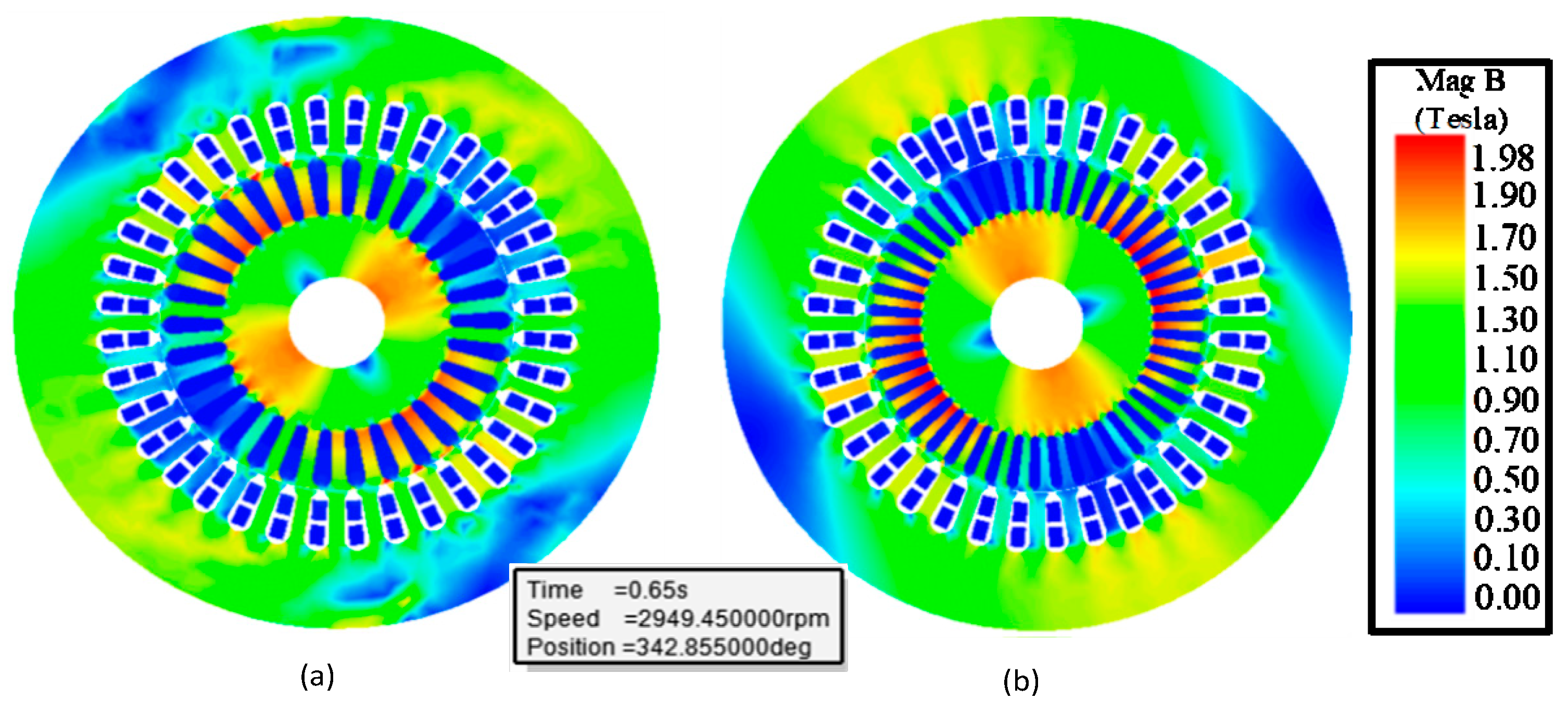
In the finite element analysis performed at a nominal load, the flux distributions of the designs are given in Figure 9.
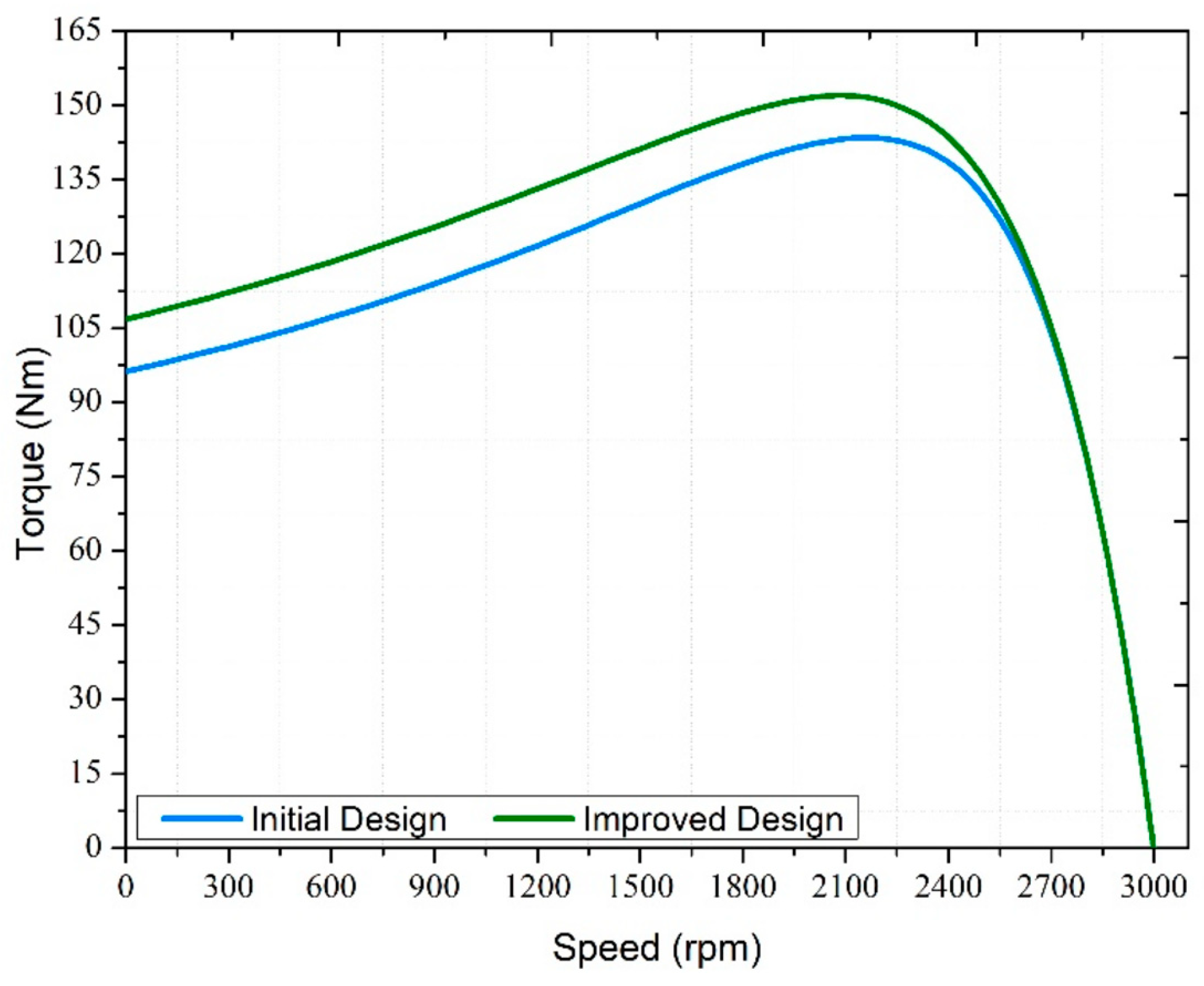
Considering the core material used in both distributions, it is seen that the flux densities of the designs are appropriate. When the initial design is examined, a higher flux density is obtained, especially in the rotor slots. The torque-speed curves of the motors for both designs are given in Figure 10.
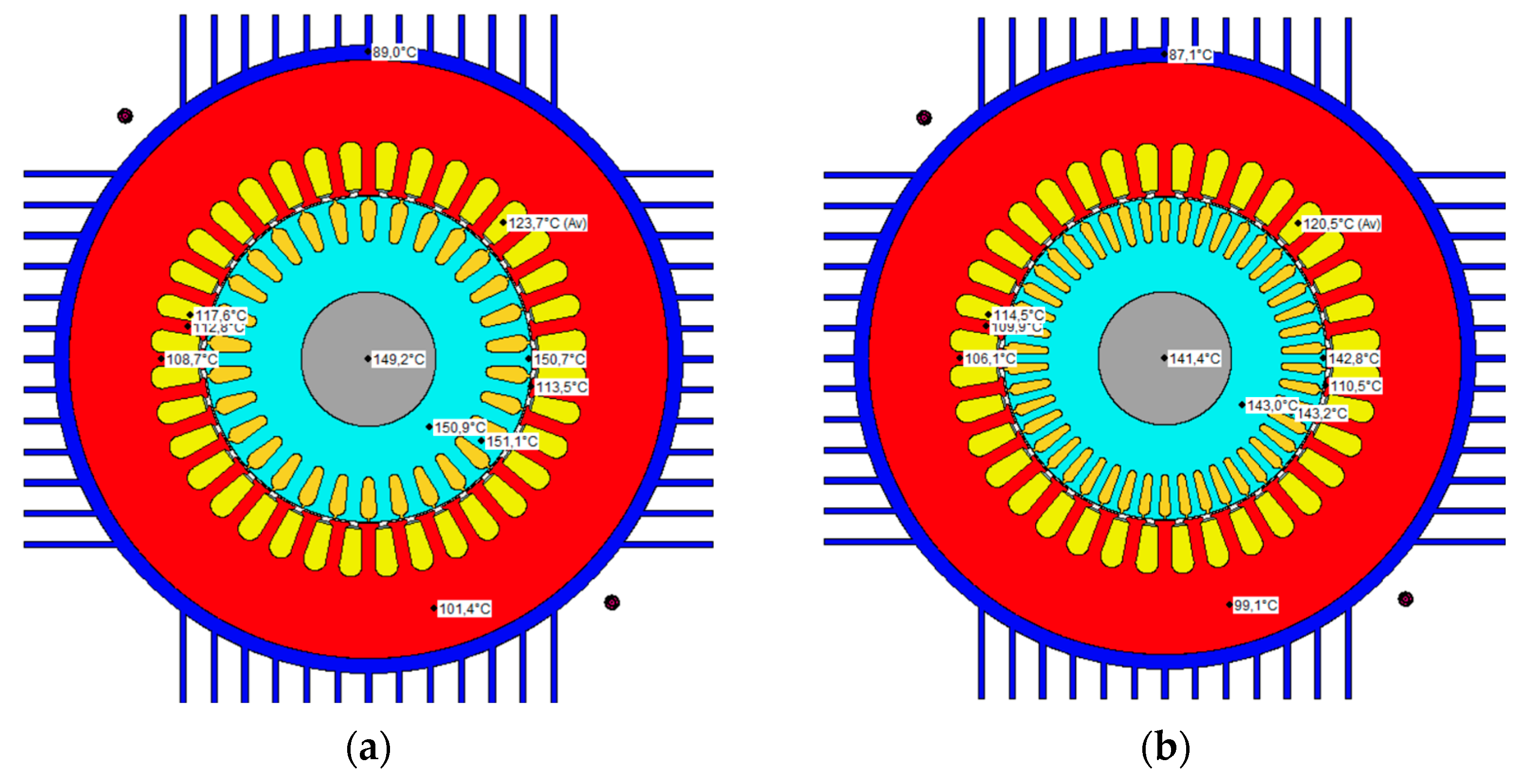
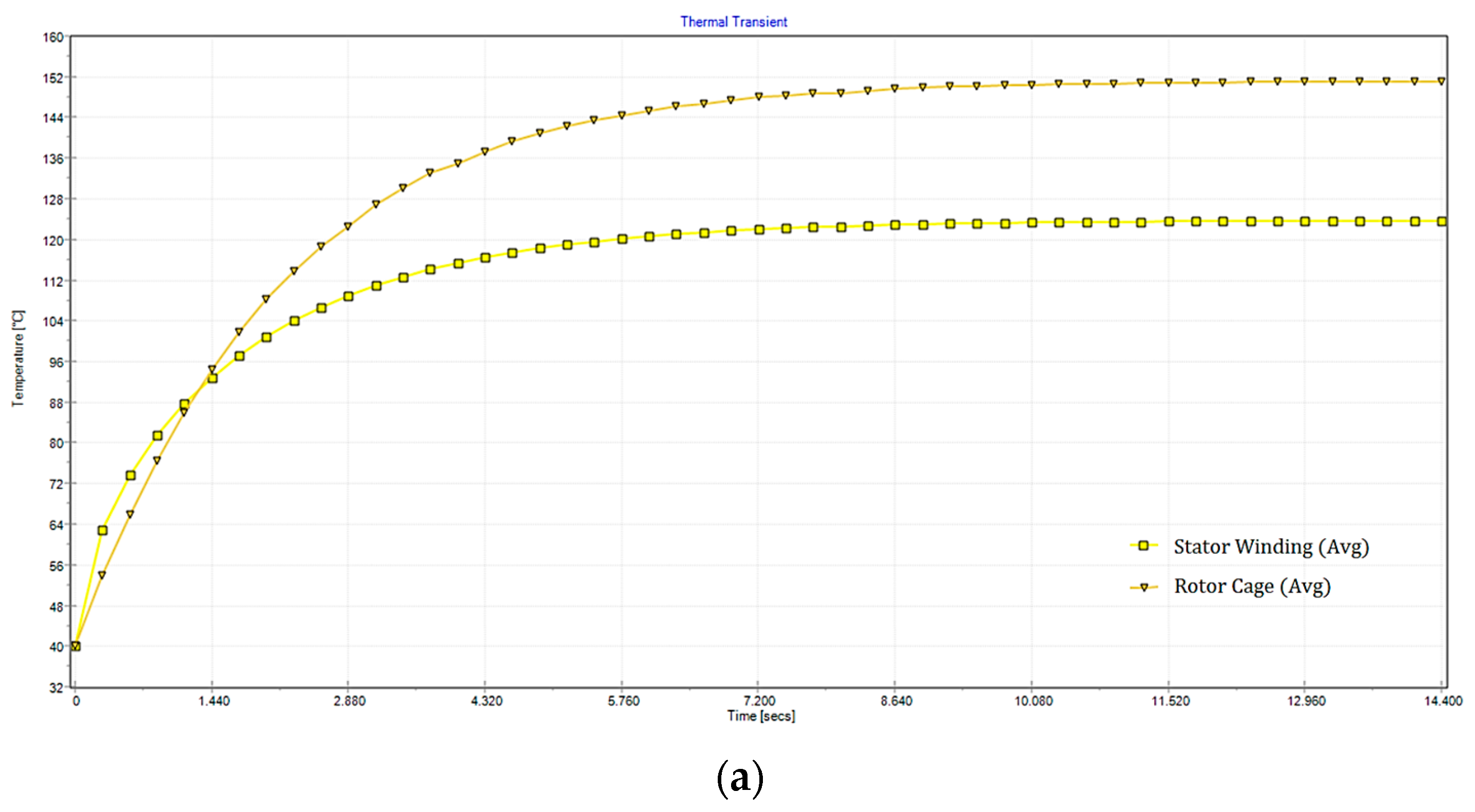
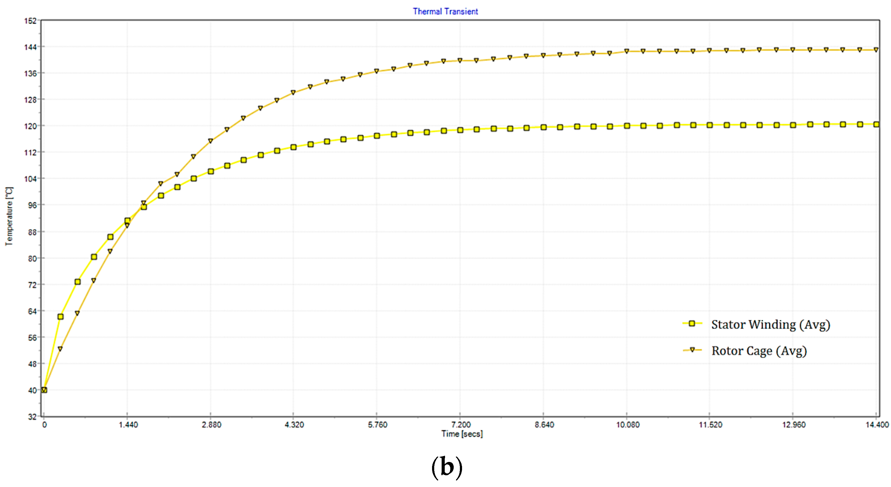
In addition to electromagnetic analyses, initial and improved designs were analyzed in Ansys Motor-CAD v14 software for a comparison of their thermal performances. Based on the analysis results presented in Figure 11, it is observed that the 36/46 improved design exhibits a lower temperature rise in both the stator and rotor. Both analyses employed the same motor housing design, and an air speed of 7 m/s was considered. While the 36/30 initial design reached a maximum stator winding temperature of T2 = 132.1 °C, the maximum stator winding temperature of the 36/46 improved design was recorded as T2 = 128.5 °C. Although stator winding structures remain consistent, resulting in similar temperature increases, the primary alteration lies in the rotor structure. Consequently, the improved design features an approximate 8 °C temperature reduction in T2, attributed to superior cooling performance stemming from increased rotor slots. The obtained temperature rise results affirm that both designs seamlessly meet the requirements of the F insulation class.
In addition to steady-state thermal analyses, transient thermal analyses have been conducted in the same way to observe the thermal equilibrium for both designs. Average stator winding and rotor cage temperatures are given in Figure 12. The improved design exhibits better performance due to lower T2 temperatures both in the stator and rotor. A higher cooling air speed on the motor frames, rather than the cooling air speed of 7 m/s which is applied in the simulation, can decrease the recorded temperatures in the given frame size.

6. Evaluation and Conclusions

The initial design of the motor developed in this study was a single-cage rotor structure with a 36/30-slot combination. Single-cage and double-cage rotors having all the physical and magnetic properties except for the slot structure were analyzed by designing them with different numbers of slots and materials. For motors with the same number of slots, it was seen that a higher starting value was obtained for the double-cage rotor type, as expected, but with lower efficiency. Among all combinations, the single-cage structure provided higher efficiency and minimum torque ripple. On the other hand, rotor resistance and starting torque increased with the double-cage structure, but this caused a decrease in the efficiency of the motor. In the case of the 36/46 combination, which was preferred in a single-cage structure, acceptable starting torques were obtained close to a double-cage structure. Therefore, a single-cage structure with a high rotor slot number should be preferred, especially for heavy-duty or traction applications. Also, a high number of rotor slots helps to improve the cooling performance of the motor. The use of copper rotor conductors significantly increases the cost. Consequently, in this study, a 36/46 single-cage structure was proposed using Al material, which is more commonly used. The improved design achieved an efficiency value of 86.8% with a starting torque value of 106.83 Nm. The starting torque was enhanced by 11% compared to the initial design, and the efficiency improved from 86.6% to 86.8%. In addition to efficiency, the output torque ripple has been decreased to 2.63, which equals a 67.32% decrease in the ripple of the initial design. The following conclusions can be drawn as a result of the analysis:
  • In the single and double cages, the starting torque value increased when the number of rotor slots increased, and the number of stator slots remained constant;
  • The double-cage rotor motor had a higher starting torque value than the single-cage rotor motor, which has the same number of stator slots/rotor slots as expected, and a difference between the rotor slot numbers is obtained;
  • The double-cage designs have higher torque ripples than single-cage designs in all the same combinations;
  • As given in the 36/34 combination, some combinations should be avoided due to high ripples. Output torque waveforms should be verified by FEM simulations;
  • The improved design has an approximately 8 °C lower T2 due to better cooling performance as a result of a higher number of rotor slots. The study contributes that the designs with a higher number of rotor slots exhibit better cooling performance even if they have the same stator winding, housing, and cooling air speed;
  • In the motor with aluminum squirrel-cage material, the loss of the rotor winding was higher than that of the copper one. However, copper cage injection is too costly, and aluminum alternatives are still more popular, both in design preference and production. So, optimal design studies closest to copper performance are still attractive;
  • The requirements of the motors operating from the mains and the VFD are different from each other. For this reason, induction motors that work with VFDs should be designed with single-cage rotors to avoid additional losses that cause lower efficiency.

Funding

This research received no external funding.

Data Availability Statement

The data used to support the findings of this study are included within the article.

Conflicts of Interest

The author declares no conflict of interest.

References

  1. Pareek, A.; Dom, R.; Gupta, J.; Chandran, J.; Adepu, V.; Borse, P.H. Insights into renewable hydrogen energy: Recent advances and prospects. Mater. Sci. Energy Technol. 2020, 3, 319–327. [Google Scholar] [CrossRef]
  2. Zhong, Z.; Zhang, Y.; Wang, S.; Deng, C.; Zhang, Y. Economic dispatch model based on time-of-use electricity price for photovoltaic systems. Arab. J. Sci. Eng. 2018, 43, 2961–2970. [Google Scholar] [CrossRef]
  3. Chan, C.C.; Bouscayrol, A.; Chen, K. Electric, Hybrid, and Fuel-Cell Vehicles: Architectures and Modeling. IEEE Trans. Veh. Technol. 2010, 59, 589–598. [Google Scholar] [CrossRef]
  4. Zeraoulia, M.; Benbouzid, M.E.H.; Diallo, D. Electric Motor Drive Selection Issues for HEV Propulsion Systems: A Comparative Study. IEEE Trans. Veh. Technol. 2006, 55, 1756–1764. [Google Scholar] [CrossRef]
  5. Sun, X.; Shi, Z.; Lei, G.; Guo, Y.; Zhu, J. Analysis and design optimization of a permanent magnet synchronous motor for a campus patrol electric vehicle. IEEE Trans. Veh. Technol. 2019, 68, 10535–10544. [Google Scholar] [CrossRef]
  6. Park, H.J.; Lim, M.S. Design of high-power density and high efficiency wound-field synchronous motor for electric vehicle traction. IEEE Access 2019, 7, 46677–46685. [Google Scholar] [CrossRef]
  7. Ehsani, M.; Gao, Y.; Gay, S. Characterization of electric motor drives for traction applications. In Proceedings of the 29th Annual Conference of the Industrial Electronics Society, Roanoke, VA, USA, 2–6 November 2003; pp. 891–896. [Google Scholar]
  8. Nanda, G.; Kar, N.C. A survey and comparison of characteristics of motor drives used in electricS vehicles. In Proceedings of the Canadian Conference on Electrical and Computer Engineering, Ottawa, ON, Canada, 7–10 May 2006; pp. 811–814. [Google Scholar]
  9. Damiano, A.; Gatto, G.; Marongiu, I.; Porru, M.; Serpi, A. Real-time control strategy of energy storage systems for renewable energy sources exploitation. IEEE Trans. Sustain. Energy. 2014, 5, 567–576. [Google Scholar] [CrossRef]
  10. Dedid, C.; Soebagio, M.; Purnomo, M.H. Induction motor speed control with fast response using the Levenberg Marquardt method for electric cars. Int. J. Comput. Appl. Technol. 2012, 42, 14–18. [Google Scholar]
  11. Libbos, E.; Ku, B.; Agrawal, S.; Tungare, S.; Banerjee, A.; Krein, P. Variable-Pole Induction Machine Drive for Electric Vehicles. In Proceedings of the IEEE International Electric Machines & Drives Conference, San Diego, CA, USA, 12–15 May 2019; pp. 515–522. [Google Scholar]
  12. Ocak, C.; Yenipınar, B. Investigation of the Effects of Hybrid-Structured Rotor Windings on Efficiency and Performance of Induction Motor. Eur. J. Sci. Technol. 2021, 26, 242–246. [Google Scholar]
  13. Xue, X.D.; Cheng, K.W.E.; Cheung, N.C. Selection of electric motor drives for electric vehicles. In Proceedings of the Australasian Universities Power Engineering Conference, Sydney, Australia, 14–17 December 2008; pp. 170–175. [Google Scholar]
  14. Guzinski, J.; Abu-Rub, H. Sensorless induction motor drive for electric vehicle application. Int. J. Eng. Sci. Technol. 2010, 2, 20–34. [Google Scholar] [CrossRef]
  15. Kim, K.T.; Song, H.E.; Park, G.S. A study on the design of induction motor in low speed urban electric vehicle. In Proceedings of the IEEE Transportation Electrification Conference and Expo, Dearborn, MI, USA, 27–29 June 2016; pp. 1–4. [Google Scholar]
  16. Li, K.; Cheng, G.; Sun, X.; Yang, Z.; Fan, Y. Performance optimization design and analysis of bearingless induction motor with different magnetic slot wedges. Results Phys. 2019, 12, 349–356. [Google Scholar] [CrossRef]
  17. Yahaya, E.A.; Omokhafe, T.; Agbachi, E.O.; James, A.G. Advantage of double cage rotor over single cage rotor induction motor. Innov. Syst. Des. Eng. 2015, 6, 1–4. [Google Scholar]
  18. Zhou, G.Y.; Shen, J.X. Current harmonics in induction machine with closed-slot rotor. IEEE Trans. Ind. Appl. 2017, 53, 134–142. [Google Scholar] [CrossRef]
  19. Gyftakis, K.N.; Kappatou, J. The impact of the rotor slot number on the behaviour of the induction motor. Adv. Power Electron. 2013, 2013, 1–9. [Google Scholar] [CrossRef]
  20. Masuku, T.M.; Wang, R.J.; Botha, M.C.; Gerber, S. Design strategy of traction induction motors. In Proceedings of the Southern African Universities Power Engineering Conference/Robotics and Mechatronics/Pattern Recognition Association of South Africa, Bloemfontein, South Africa, 28–30 January 2019; pp. 316–321. [Google Scholar]
  21. Wolnik, T.; Styskala, V.; Mlcak, T. Study on the Selection of the Number of Magnetic Poles and the Slot-Pole Combinations in Fractional Slot PMSM Motor with a High Power Density. Energies 2022, 15, 215. [Google Scholar] [CrossRef]
  22. Chasiotis, I.D.; Karvanas, Y.L.; Scuiller, F. Effect of Rotor Bars Shape on the Single-Phase Induction Motors Performance: An Analysis toward Their Efficiency Improvement. Energies 2022, 15, 717. [Google Scholar] [CrossRef]
  23. Elhaija, W.A.; Ghorbanian, V.; Faiz, J.; Nejadi-Koti, H. Significance of rotor slots number on induction motor operation under broken bars. In Proceedings of the IEEE International Electric Machines and Drives Conference, Miami, FL, USA, 21–24 May 2017. [Google Scholar]
  24. Park, H.J.; Hong, H.B.; Lee, K.D. A Study on a Design Considering the Transient State of a Line-Start Permanent Magnet Synchronous Motor Satisfying the Requirements of the IE4 Efficiency Class. Energies 2023, 15, 9644. [Google Scholar] [CrossRef]
  25. Ion, C.P.; Calin, M.D.; Peter, I. Design of a 3 kW PMSM with Super Premium Efficiency. Energies 2023, 16, 498. [Google Scholar] [CrossRef]
  26. Lu, C.; Yang, Z.; Sun, X.; Ding, Q. Design and Multi-Objective Optimization of a Composite Cage Rotor Bearingless Induction Motor. Electronics 2023, 12, 775. [Google Scholar] [CrossRef]
  27. Marfoli, A.; Nardo, M.D.; Degano, M.; Gerada, C.; Chen, W. Rotor Design Optimization of Squirrel Cage Induction Motor—Part I: Problem Statement. IEEE Trans. Energy Convers. 2021, 36, 1271–1279. [Google Scholar] [CrossRef]
  28. Nardo, M.D.; Marfoli, A.; Degano, M.; Gerada, C.; Chen, W. Rotor Design Optimization of Squirrel Cage Induction Motor—Part II: Results Discussion. IEEE Trans. Energy Convers. 2021, 36, 1280–1288. [Google Scholar] [CrossRef]
  29. Juhaniya, A.I.S.; Ibrahim, A.A.; Mohd Zainuri, M.A.A.; Zulkifley, M.A.; Remli, M.A. Optimal Stator and Rotor Slots Design of Induction Motors for Electric Vehicles Using Opposition-Based Jellyfish Search Optimization. Machines 2022, 10, 1217. [Google Scholar] [CrossRef]
  30. Nell, M.; Kubin, A.; Hameyer, K. Multi-Stage Optimization of Induction Machines Using Methods for Model and Parameter Selection. Energies 2021, 14, 5537. [Google Scholar] [CrossRef]
  31. Wogi, L.; Thelkar, A.; Tahiro, T.; Ayana, T.; Urooj, S.; Larguech, S. Particle Swarm Optimization Based Optimal Design of Six-Phase Induction Motor for Electric Propulsion of Submarines. Energies 2022, 15, 2994. [Google Scholar] [CrossRef]
  32. Tripathy, S.N.; Kundu, S.; Pradhan, A. Multi-Objective Optimization Technique Based Design of Squirrel Cage Induction Motor. In Proceedings of the 2022 2nd International Conference on Power Electronics & IoT Applications in Renewable Energy and Its Control (PARC), Mathura, India, 21–22 January 2022; pp. 1–6. [Google Scholar]
  33. Hannan, M.A.; Azidin, F.A.; Mohamed, A. Multi-sources model and control algorithm of an energy management system for light electric vehicles. Energy Convers. Manag. 2012, 62, 123–130. [Google Scholar] [CrossRef]
  34. International Electrotechnical Commission- IEC 60034-30-1 Ed.1: Rotating electrical machines—Part 30-1: Efficiency classes of line operated AC motors (IE code). 2014. Available online: https://webstore.iec.ch/publication/136 (accessed on 5 August 2023).
  35. Goman, V.; Prakht, V.; Kazakbaev, V.; Dmitrievskii, V. Comparative Study of Induction Motors of IE2, IE3 and IE4 Efficiency Classes in Pump Applications Taking into Account CO2 Emission Intensity. Appl. Sci. 2020, 10, 8536. [Google Scholar] [CrossRef]
  36. Kreveld, P. Don’t Rush In. Available online: https://electricalconnection.com.au/dont-rush-in/ (accessed on 5 August 2023).
  37. Ferreira, F.J.T.E.; Leprettre, B.; de Almeida, A.T. Comparison of Protection Requirements in IE2-, IE3-, and IE4-Class Motors. IEEE Trans. Ind. Appl. 2016, 52, 3603–3610. [Google Scholar] [CrossRef]
  38. Tomizawa, K.; Nagasawa, K.; Hayashi, Y.; Matsumoto, T. Low Starting Current Motor Developed for Top Runner Model. Meiden Rev. Ser. 2018, 172, 17–20. [Google Scholar]
  39. Technical Bulletin—WEG: Conform to IE3 Motors. Available online: https://www.mak.nl/pdfbrochures/WEG-technical-bulletin-weg-conform-to-ie3-motors-50059073-technical-article-english.pdf (accessed on 5 August 2023).
  40. Lee, G.; Min, A.; Hong, J.P. Optimal shape design of rotor slot in squirrel-cage induction motor considering torque characteristic. IEEE Trans. Magn. 2013, 49, 2197–2200. [Google Scholar] [CrossRef]
  41. Zhanh, D.; Park, C.S.; Koh, C.S. A new optimal design method of rotor slot of three-phase squirrel cage induction motor for NEMA class D speed-torque characteristic using multi-objective optimization algorithm. IEEE Trans. Magn. 2012, 48, 879–882. [Google Scholar]
  42. Lipo, T.A. Introduction to AC Machine Design; John Wiley & Sons: Hoboken, NJ, USA, 2017. [Google Scholar]
  43. Hase, Y.; Khandelwal, T.; Kameda, K. Power System Dynamics with Computer-Based Modeling and Analysis; John Wiley & Sons: Hoboken, NJ, USA, 2020. [Google Scholar]
  44. Available online: https://new.abb.com/motors-generators# (accessed on 5 August 2023).
  45. Dalcalı, A.; Ocak, C. Effect of different magnet materials on the performance of surface mounted direct drive PMSM. J. Aware. 2018, 3, 217–224. [Google Scholar] [CrossRef]
  46. Popescu, M.; Goss, J.; Staton, D.A.; Hawkins, D.; Chong, Y.C.; Boglietti, A. Electrical vehicles—Practical solutions for power traction motor systems. IEEE Trans. Ind. Appl. 2018, 54, 2751–2762. [Google Scholar] [CrossRef]
  47. Duan, Y. Method for Design and Optimization of Surface Mount Permanent Magnet Machines and Induction Machines. Ph.D. Dissertation, Georgia Institute of Technology, Atlanta, Georgia, 2010. [Google Scholar]
  48. Upadhyay, K.G. Design of Electrical Machines; New Age International Limited Publications: Delhi, India, 2011. [Google Scholar]
  49. Dalcalı, A.; Akbaba, M. Comparison of 2D and 3D magnetic field analysis of single-phase shaded pole induction motors. Eng. Sci. Technol. Int. J. 2016, 19, 1–6. [Google Scholar] [CrossRef]
  50. Ünlükaya, E.; Yetgin, A.G.; Çanakoğlu, A.I.; Turan, M. Effect of rotor slot shapes on induction motor performance. In Proceedings of the Symposium on Electrical-Electronic-Computer and Biomedical Engineering, Bursa, Türkiye, 27–29 November 2014; pp. 168–172. [Google Scholar]
  51. Besnerais, J.L.; Lanfranchi, V.; Hecquet, M.; Brochet, P. Optimal slot numbers combination for magnetic noise reduction in variable-speed induction motors. IEEE Trans. Magn. 2009, 45, 3131–3136. [Google Scholar] [CrossRef]
  52. Finley, W.R.; Hodowanec, M.M. Selection of copper vs. aluminum rotors for induction motors. In Proceedings of the Industry Applications Society Forty-Seventh Annual Petroleum and Chemical Industry Conference, San Antonio, TX, USA, 11–13 September 2000; pp. 1–11. [Google Scholar]
  53. Popescu, M.; Riviere, N.; Volpe, G.; Villani, M.; Fabri, G.; di Leonardo, L. A copper rotor induction motor solution for electrical vehicles traction system. In Proceedings of the IEEE Energy Conversion Congress and Exposition, Baltimore, MD, USA, 29 September–3 October 2019; pp. 3924–3930. [Google Scholar]
  54. Zhang, Q.; Liu, H.; Zhang, Z.; Song, T. A cast copper rotor induction motor for small commercial EV traction: Electromagnetic design, analysis, and experimental tests. CES Trans. Electr. Mach. Syst. 2018, 2, 417–424. [Google Scholar] [CrossRef]
  55. Gieras, J.F. Advancements in Electric Machines; Springer: Berlin/Heidelberg, Germany, 2008. [Google Scholar]
  56. Brush, E.F.; Cowie, J.G.; Peters, D.T.; Van Son, D.J. Die-cast copper motor rotors: Motor test results, copper compared to aluminum. Energy Effic. Mot. Driven Syst. 2003, 136–143. [Google Scholar] [CrossRef]
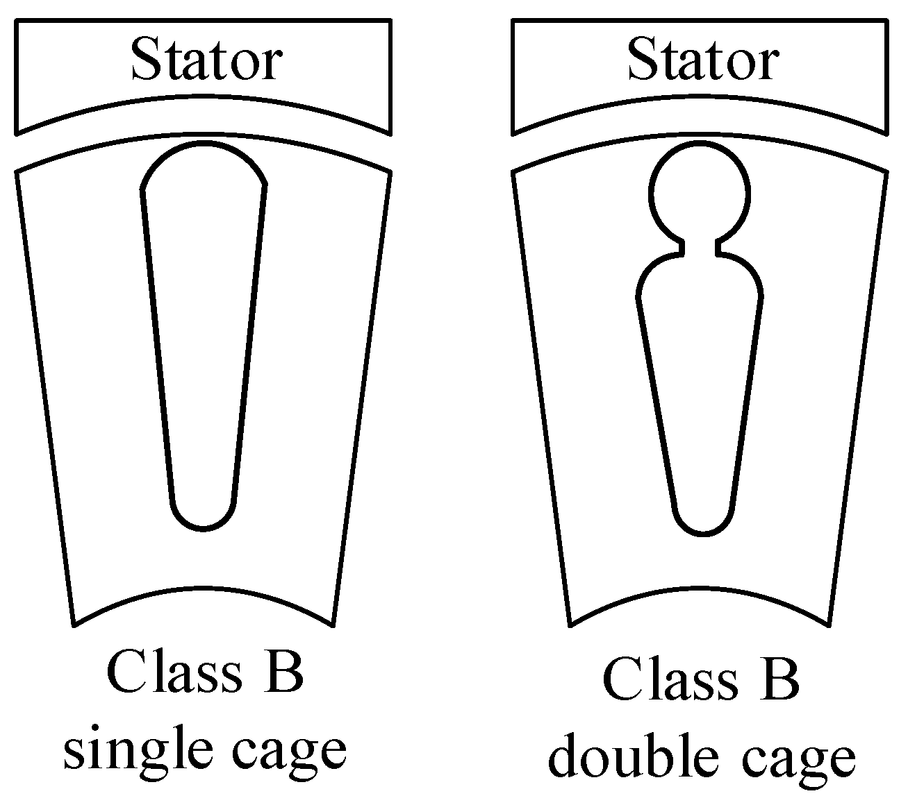
Figure 1. Slot structure.
Energies 16 06047 g001
Figure 2. 2D and 3D models of the initial design.
Energies 16 06047 g002
Figure 3. Torque-speed characteristic curves in a single-cage rotor.
Energies 16 06047 g003
Figure 4. Comparison of torque waveforms and ripples of single-cage designs obtained by 2D transient FEM simulation.
Energies 16 06047 g004
Figure 5. Torque-speed characteristic curves in a double-cage rotor.
Energies 16 06047 g005
Figure 6. Comparison of torque waveforms and ripples of double-cage designs obtained by 2D transient FEM simulation.
Energies 16 06047 g006
Figure 7. Torque-speed characteristic curves (a) single-cage, (b) double-cage.
Energies 16 06047 g007
Figure 8. The 2D models of the initial and improved designs (a) initial, (b) improved.
Energies 16 06047 g008
Figure 9. Magnetic flux density distributions (a) 36/30 initial design, (b) 36/46 improved design.
Energies 16 06047 g009
Figure 10. Torque-speed characteristic curves.
Energies 16 06047 g010
Figure 11. Steady-state thermal analysis results (a) 36/30 initial design, (b) 36/46 improved design.
Energies 16 06047 g011
Figure 12. Transient thermal analysis results (a) 36/30 initial design (b) 36/46 improved design.
Energies 16 06047 g012aEnergies 16 06047 g012b
Table 1. Design parameters.
ParameterValue
Motor type3 phase, squirrel cage
Output power7.5 kW
Rated frequency50 Hz
Number of poles2
Rated speed2949 rpm
Slot fill factor53.52%
StatorOuter diameter200 mm
Inner diameter110 mm
Length140 mm
Number of slots36
Skew width0
Number of conductors per slot28
Type of SteelM530-50A
RotorOuter diameter109.4 mm
Inner diameter35 mm
Length140 mm
Number of slots30
Skew width1
Type of SteelM530-50A
Squirrel-cage materialAluminum
Table 2. Single-cage performance of motors with different numbers of rotor slots.
Number of ST/RT SlotsRated Load Efficiency (%)Rated Load Losses (W)Rated Load Power FactorStator/Rotor Current Density (A/mm2)Rated Torque (Nm)Starting Torque (Nm)Total Weight (kg)
Energies 16 06047 i00186.61PTotal: 1159.6
PCore: 321.7
PSt_Cu: 320.8
PRt_Cu: 133
Pf&w: 241.6
PStray: 142.5
0.8804.85/2.4724.2891.8830.20
Energies 16 06047 i00286.64PTotal: 1155.6
PCore: 321.4
PSt_Cu: 316.8
PRt_Cu: 133.3
Pf&w: 241.6
PStray: 142.5
0.8854.82/2.4924.2994.2130.22
Energies 16 06047 i00386.67PTotal: 1153.4
PCore: 321.6
PSt_Cu: 314.4
PRt_Cu: 133.3
Pf&w: 241.6
PStray: 142.5
0.8884.81/2.5124.2896.2630.24
Energies 16 06047 i00486.73PTotal: 1147.3
PCore: 320.7
PSt_Cu: 308.5
PRt_Cu: 134
Pf&w: 241.6
PStray: 142.5
0.8964.76/2.5424.28100.2730.26
Energies 16 06047 i00586.79PTotal: 1140.7
PCore: 321
PSt_Cu: 301.2
PRt_Cu: 134.5
Pf&w: 241.5
PStray: 142.5
0.9064.70/2.5824.28106.0430.29
Energies 16 06047 i00686.80PTotal: 1140.5
PCore: 321.1
PSt_Cu: 300.9
PRt_Cu: 134.5
Pf&w: 241.5
PStray: 142.5
0.9074.70/2.5824.28106.8330.29
Table 3. Performance of motors with different numbers of rotor slots.
Number of ST/RT SlotsRated Load Efficiency (%)Rated Load Losses (W)Rated Load Power FactorStator/Rotor Current Density (A/mm2)Rated Torque (Nm)Starting Torque (Nm)Total Weight (kg)
Energies 16 06047 i00786.31PTotal: 1189
PCore: 317.5
PSt_Cu: 325.3
PRt_Cu: 164
Pf&w: 239.7
PStray: 142.5
0.8784.88/3.4924.38100.3230.58
Energies 16 06047 i00886.36PTotal: 1184.4
PCore: 317.7
PSt_Cu: 321.8
PRt_Cu: 162.5
Pf&w: 239.9
PStray: 142.5
0.8824.86/3.4224.37103.1330.56
Energies 16 06047 i00986.41PTotal: 1178.5
PCore: 318
PSt_Cu: 316.1
PRt_Cu: 162
Pf&w: 239.9
PStray: 142.5
0.8894.81/3.4524.37104.5430.57
Energies 16 06047 i01086.48PTotal: 1171.8
PCore: 318.4
PSt_Cu: 311.9
PRt_Cu: 159
Pf&w: 240
PStray: 142.5
0.8944.78/3.3724.36108.1730.54
Energies 16 06047 i01186.55PTotal: 1164.7
PCore: 319.5
PSt_Cu: 311.9
PRt_Cu: 150.2
Pf&w: 240.6
PStray: 142.5
0.8944.78/3.0924.33114.9530.42
Energies 16 06047 i01286.60PTotal: 1160.6
PCore: 319.1
PSt_Cu: 306.8
PRt_Cu: 151.7
Pf&w: 240.5
PStray: 142.5
0.94.75/3.1524.34115.3430.45
Table 4. Motor performance with aluminum and copper cages.
Aluminum Cage (36/46)Copper Cage (36/46)
Single CageDouble CageSingle CageDouble Cage
Rotor ohmic losses (W)134.54151.7175.4184.87
Rotor resistance (Ω)0.86040.96510.48950.5491
Efficiency (%)86.8086.6087.3887.26
Starting torque (Nm)106.83115.3482.6391.85
Rated torque (Nm)24.2824.3424.0924.13
Total net weight (kg)30.2930.4533.7133.46
Table 5. Performance of the initial and improved designs.
DescriptionRotor Structure
Initial Design (36/30)Improved Design (36/46)
Efficiency (%)86.686.8
Rotor teeth flux density (T)1.7831.786
Rated torque (Nm)24.2824.28
Starting torque (Nm)96.26106.83
Total weight (kg)30.2430.29
Disclaimer/Publisher’s Note: The statements, opinions and data contained in all publications are solely those of the individual author(s) and contributor(s) and not of MDPI and/or the editor(s). MDPI and/or the editor(s) disclaim responsibility for any injury to people or property resulting from any ideas, methods, instructions or products referred to in the content.