Article

Experimental Study on Flow Boiling Characteristics in Continuous and Segmented Microchannels with Vapor Venting Membrane

School of Energy and Power Engineering, Shandong University, Jinan 250061, China
*
Author to whom correspondence should be addressed.
Energies 2022, 15(22), 8756; https://doi.org/10.3390/en15228756
Submission received: 24 October 2022 / Revised: 15 November 2022 / Accepted: 17 November 2022 / Published: 21 November 2022
(This article belongs to the Section J: Thermal Management)

Abstract

:
Flow boiling in microchannels is one of the promising techniques for heat dissipation occurred in micro devices. However, the rapid bubble growth must be suppressed, which leads to serious boiling instabilities, high pressure drop, and low heat transfer coefficient. The addition of porous hydrophobic membrane has proven an effective method to remove the vapor in-site in the literature. However, the effects of heat sink’s topological structures on the vapor venting are still a research gap. The present study experimentally investigates the influence of Polytetrafluoroethylene (PTFE) membrane on fluid flow pattern, pressure drop, vapor venting performance, and heat transfer characteristics of flow boiling in the continuous and segmented heat sinks. Results show that the vapor venting membrane can reduce the pressure drop and increase the heat transfer coefficient effectively by decreasing the exit vapor quality, especially in combination with the segmented structures. The interconnection area as a space for bubble growth and coalescence is beneficial for vapor venting due to increased vapor pressure and quantity. Following the enhanced vapor discharge, the fluctuation of pressure drop is further weakened, which is conducive for the safe operation of heat sink.

1. Introduction

Due to the needs of cooling technology in modern industrial applications, the research on microchannel heat sinks has received increasing attention. Miniaturization has led to high heat exchange capability associated with a large surface area to volume ratio. Since first proposed by Tuckerman and Pease [1], who employed the single-phase heat transfer, numerous studies have focused on how to further improve the heat dispersion performance with less pressure drop. However, the characteristics of single-phase flow determine that higher flow rates must be employed to obtain more uniform temperature distribution along the channels and better heat transfer coefficient. This must consume more pump works and decrease the efficiency of a cooling system. To break through this bottleneck, many researchers emphasized the introduction of two-phase heat transfer in microchannel heat sinks.
Many studies in the literature proved that the flow boiling in microchannels is one of the promising techniques for heat dissipation occurred in microelectronics and microreactors. The flow boiling in microchannels combines the advantages of micro-scale and phase change effect so that it can achieve a greater heat transfer coefficient than single-phase flow [2]. However, to take full benefit of flow boiling in microchannels, the extra pressure drop and the boiling instabilities caused by the rapid bubble growth in microchannels must be suppressed, which leads to low critical heat flux (CHF) [3], high pressure and temperature oscillation, or even large peak temperature [4].
One of the effective solutions is to modify the geometrical structures of heat sinks, such as flow passage modification [5,6,7,8], reentrant cavity design [9,10,11] and inlet configuration design [12,13,14]. The general idea is to change the flow pattern and flow instability properties through influencing the bubble behaviors inside the microchannel [2]. It should be noted that the relationship between geometrical structures and flow instability is still not clear, and the trial-and-error tests are inevitable to find an available structures.
Other researchers proposed to modify the physical properties of working fluid by adding low concentrations of nanoparticles [15,16,17]. Although a minority of studies reported contradictory conclusions [18], the prevailing viewpoint is that nanofluid could enhance the heat transfer performance and suppress the boiling instability with proper microchannel dimension and operation conditions. However, the nanoparticles trend to deposit together and adhere on the surface of channels which lead to decreased heat transfer performance and even blockage of microchannels [19].
Another common solution to the boiling instability problem is modifying the surface characteristics of heat sinks by different coatings to change the roughness, wettability, and density of the active nucleation site. The comprehensive reviews can be found in Mao et al. [2]. The main types of coatings are silicon or metal nanowires, carbon nanotubes, and porous coating. Regardless of which coating is used, however, the manufacturing costs are bound to rise. Meanwhile, the durability of these coatings in boiling should be further confirmed. Once the coating failure happens, even in some local point, the whole heat sink must be replaced for preventing equipment damage.
Note that the problems existed in boiling heat transfer in microchannels are mainly due to the rapid bubble growth. A natural response is to remove the vapor in-site to avoid the bubble growth and expansion, which is the vapor venting method. To the best of the authors’ knowledge, the vapor venting microchannel heat exchanger was firstly proposed by Zhou et al. [20]. Several other studies at the same period could also enlighten us, even just involving gas-liquid two phase flow without boiling. Meng et al. [21,22] proposed a multi-hole wall plate to remove CO2 from direct methanol fuel cells. The gas bubbles of CO2 are generated from the electrochemical reactions, not by fluid boiling. Alexander and Wang [23] designed breather ports positioned directly across from a bubble nucleation site in a microchannel. To emulate the boiling in heat sinks, water and gas were employed in their experiments instead of water and vapor. Later, limited but compelling studies were reported to prove that the vapor venting method could reduce the pressure drop of heat sink and suppress the boiling instability. David et al. [24,25] first investigated the vapor venting heat sinks which are attached to a silicon thermal test chip. The membrane used in their study is Polytetrafluoroethylene (PTFE). They found that the pressure drop in the venting devices is prominently lower than that in non-venting devices, while the boiling instabilities could be improved. However, the amelioration on the heat transfer coefficients is ambiguous because of the changes in flow regime. To predict the extraction rates and the effect of extraction on the fluid flow and heat transfer, Salakij et al. [26] developed a physics-based model for the transition criteria among the extraction mechanism regimes and the extraction flow regimes for microscale flow boiling. Due to the usage of several nubilous assumptions, the models should be further validated for further applications.
It can be found in the literature that the improvement of vapor venting method on the performance of heat sink system is significantly related to the fluid flow characteristics. As is known to us all, the geometric constructions in microchannels affect fluid flow condition. Mohiuddin et al. [27] studied experimentally the effect of the channel aspect ratio with vapor venting membrane. The results show that the pressure drop and heat transfer coefficient are influenced significantly by the channel aspect ratio and the flow mass flux. However, a consistent trend is hard to be concluded based on the exhibited results. Meanwhile, only one channel was employed in their study without any channel combination.
The above example reveals the influence of single microchannel’s geometrical shape on the vapor venting, which makes us have reasons to believe that the topological structures of parallel microchannels also affect the performance of vapor venting. However, little investigation has been undertaken in this field. Therefore, the main objective of the present study is to investigate the influence of microchannel structures on the vapor venting, as well as the heat transfer and pressure drop characteristics of the flow boiling in microchannels. For this purpose, two heat sinks with conventional and segmented microchannel structures are designed, fabricated and installed to test experimentally their influences on the vapor venting, the fluid flow pattern, the pressure drop, and the heat transfer characteristics under different mass and heat fluxes. The segmented network has been proven to reduce the flow instabilities due to the connected region which supplies a place for bubble coalescence [10,28]. The sudden narrowing downstream of the connected region may cause extra pressure for vapor venting. This design also follows the principles for the vapor venting device proposed in David et al. [25] that the liquid channels should be long with small hydraulic diameter and the vent channels are just the opposite.
In the rest of this paper, we shall first introduce the heat sinks with vapor venting membrane and the experimental setup used in this study. Then, fluid flow and heat transfer characteristics under different operation conditions will be presented and discussed. Finally, main conclusions and perspectives will be summarized.

2. PTFE Membrane and Experimental Set-Up

2.1. Characterization of Vapor Venting Membrane

The vapor venting method is to separate a part of the vapor out from the fluid in microchannels using a porous membrane which allows the vapor to pass but not the fluid. The porous vapor venting membrane used in this study is unlaminated PTFE membrane (T050A047A, Advantec) which has high permeability, ultra-hydrophobicity, high temperature tolerances, high chemical resistance, and excellent robustness. A SEM image of an unused PTFE membrane is shown in Figure 1. The PTFE membrane allows gases to pass freely while blocking aqueous liquids. More detailed specifications according to the information released by the manufacturer are listed in Table 1.
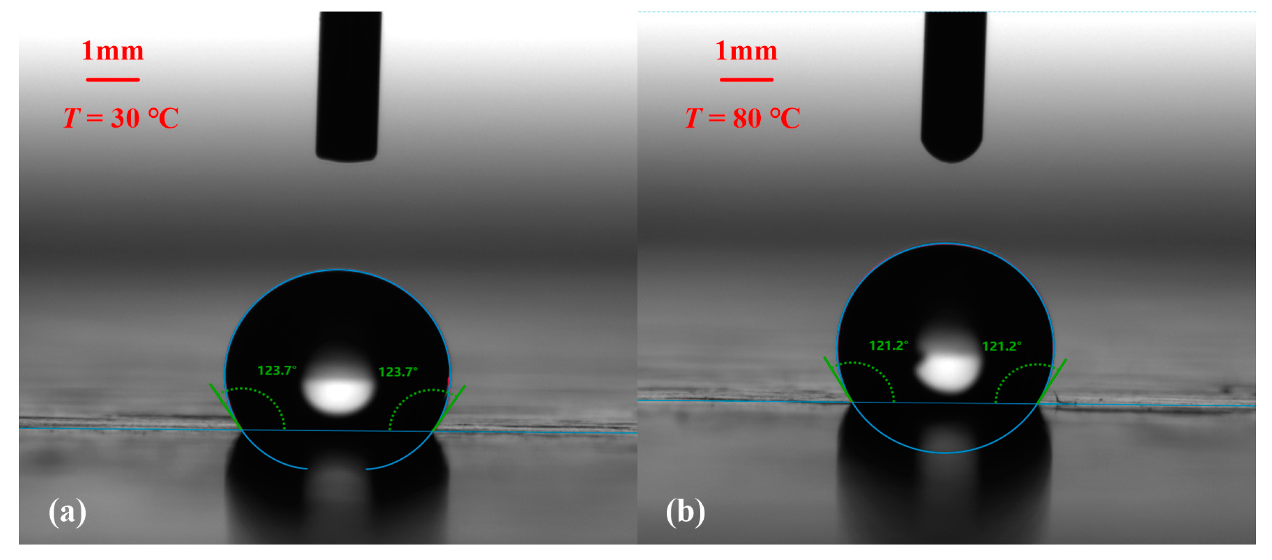
Generally speaking, the hydrophobic membranes are suitable for vapor venting. For further validation, the hydrophobicity of PTFE is tested by contact angle meter (DSA25, KRUSS) using sessile drop technique in a thermostatic chamber under the temperature variation from 30 °C to 90 °C, with an interval of 10 °C. For each temperature, the measurement is repeated by five times to have the averaging value. Figure 2 shows one of the images under 30 °C and 80 °C, respectively, with the static contact angles of 123.7° and 123.2°. Noted that the method used for fitting the drop outline is the Young-Laplace method. It can be found from Figure 3 that the static contact angle varies little with the change of temperature.
The theoretical breakthrough pressure or the liquid leakage pressure for the membrane is estimated as follows [21]:
Δ p max = 4 σ cos ( π θ a d v , max ) d p
in which dp is the pore size, θadv is the dynamic advancing contact angle and σ is the surface tension of working fluid. Note that the dynamic advancing contact angle is considerably different from the equilibrium contact angle so that we also measure it under different temperatures with the same contact angle meter. As shown in Figure 3, the dynamic advancing contact angle also changes slightly under different temperatures, considering the measuring errors. Based on Equation (1), the theoretical breakthrough pressure for the membrane used in this study is about 206 kPa for water at 90 °C. This value is smaller than 600 kPa under 100 °C, which is reported in David et al. [25], due to different pore sizes of membrane. However, the film strength is also enough for avoiding the water leakage in this study. In fact, the dynamic advancing contact angle is strongly influenced by the surface topography, especially the surface roughness which is not directly expressed in Equation (1). For reference, the surface roughness of PTFE used in this study is measured by a roughmeter (SJ-210, Mitutoyo) and the value of Ra is about 0.78 μm which also has no evident changes with the temperature, as shown in Figure 3.

2.2. Experimental Set-Up

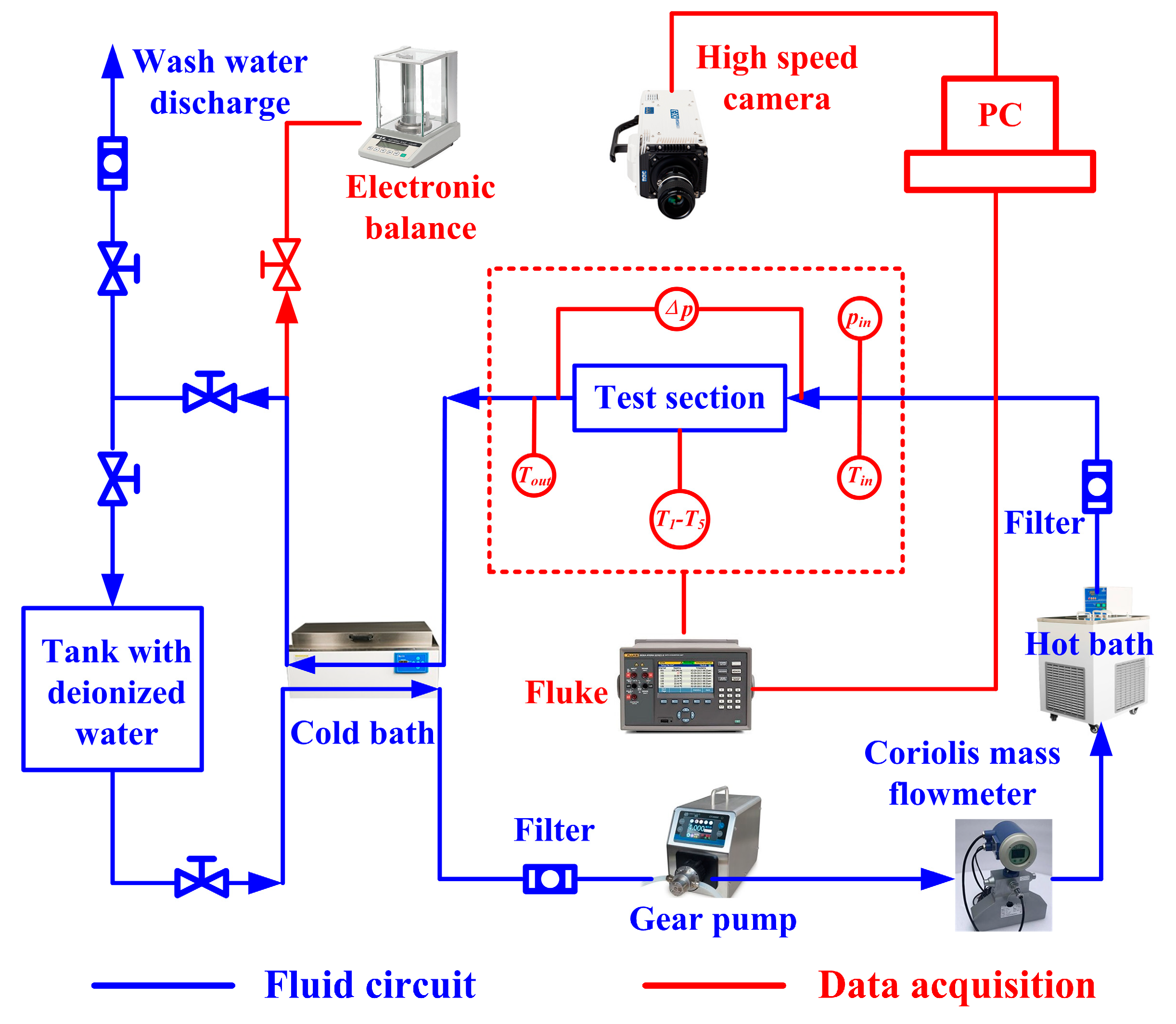
Figure 4 shows a schematic diagram of the experimental set-up used in this study. It is composed of a fluid circuit and data acquisition system. Deionized water is used as the working fluid. In the fluid circuit, water is pumped from a water tank, then passes through the flowmeter and the test module, and finally returns back to the water tank to form a closed loop. The pump used is a micro-gear pump (CT3000F, Leadfluid) with a measurement range of 15–900 mL min−1. The actual output mass flow-rate is measured by a Coriolis mass flow meter (DS-CMF1-DN1, DOYI). The liquid inlet pressure is measured by a pressure transmitter (PSC.H101, BOOST) with the low-pressure end to the atmosphere. Meanwhile, the pressure drop occurred by the heat sink is obtained using another differential pressure transmitter (3051CD2A22A1AB4M5HR5, Rosemount). All measured pressure and temperature data are collected by Fluke 2638A.
Before the experiments, the deionized water is boiled to remove the dissolved non-condensable gases. Then, the treated deionized water must be cooled below 40 °C by a cold bath to meet the requirement of the pump’s working temperature. A water bath preheater is used before the deionized water entering the test module to control the inlet temperature. In our experiments, the inlet temperature is set as 70 °C. After the test module, the fluid passes the cold bath again to ensure that the vapor is completely condensed. The condensed water is weighted by a precision electronic balance in a certain time interval to calculate the mass of discharge vapor through the membrane.
A high-speed camera (NAC Company, HX-6) installed above the test module is used to record the process of water boiling in microchannels. This camera has 5 megapixels, and the maximum speed is 650,000 frames per second. In this study, the actual recording speed is 1000 frames per second, and the resolution is 1920 × 480 pixels, as determined after several tests. To make the images clearer, a LED spotlight is employed to provide a setting light source.

2.3. Test Module

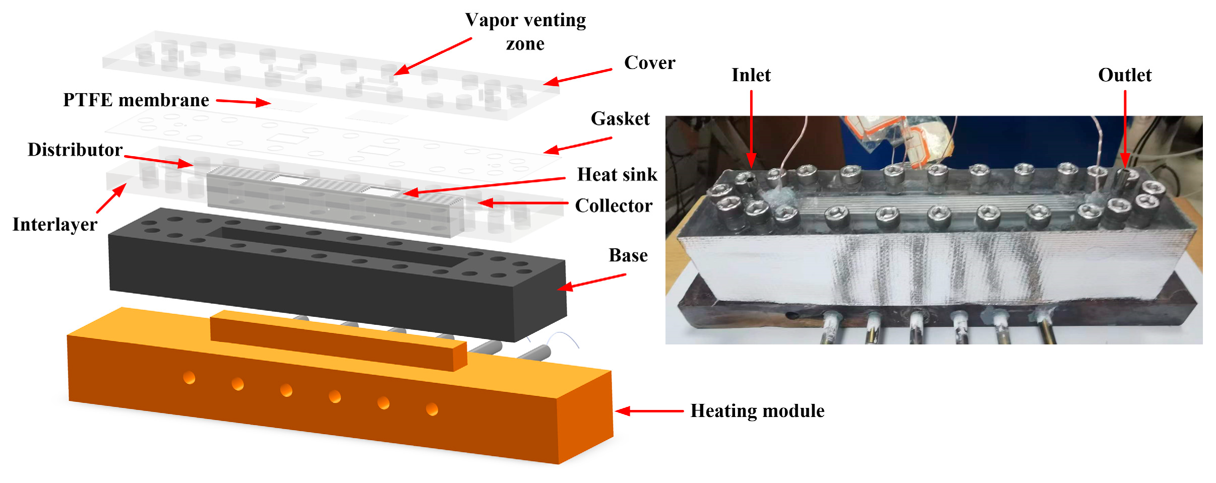
Figure 5 illustrates the assembly diagram and photography of the test module used in this study. The test module consists of three parts: the heat sink with microchannel fluidic network, the shell, and the heating module. There are 7 parallel straight channels with the identical width of 0.8 mm, length of 120 mm, and depth of 0.8 mm on the heat sink, milled on the aluminum block by Computer Numerical Control (CNC) machine in our laboratory in Shandong University, China. The in-house fabrication tolerance used in this study is 0.01 mm. The distance between the axis of one channel and another is evenly spaced at 1.6 mm so that the fin thickness is also 0.8 mm. For the segmented heat sink, two areas of 10.4 mm × 15 mm are connected without fins, as shown in Figure 6. For monitoring the temperature, five T-thermocouples (accuracy of 0.2 K) are embedded at 1 mm under the microchannel bottom surface with a separation distance of 22.5 mm. These thermocouples can obtain the temperature distributions along the heat sink which are also used to calculate the wall temperature corrected by Fourier’s law [29].
The heating module is made of a copper block with a high thermal conductivity coefficient. A lug boss is fabricated with the same dimension of heat sink for more efficient heating. The thermal conductive silicone is applied on the upper surface of the lug boss for better contact between the heating module and the heat sink. Six cartridge heaters in parallel connection are inserted into the copper block to supply heating power. The power of the cartridge heater can be adjusted by changing the voltage with a voltage regulator.
The shell is made of Polycarbonate with high transparency and heat stability under 130 °C. The shell has four parts: the cover, the interlayer, the base, and the gasket. On the interlayer, an area is hollowed out for placing the heat sink in. In actual operation, the heat sink adheres with the interlayer via high temperature resistant adhesives. Meanwhile, a distributor and a collector are also curved on the interlayer with the same depth of channels. On the cover part, two holes with diameter of 4 mm are reserved which are used as inlet and outlet for fluid flow and the pressure taps, corresponding to the locations of distributor and collector. Beside them, two small apertures are punched for inserting two more T-thermocouples to acquire the temperature data of inlet and outlet. Located above the interconnection areas, two vapor venting zones with the same dimensions are designed when the venting membrane is installed. Each vapor venting zone is connected with two holes which are used as air blowing to avoid the steam condensation on the upper surface of the venting membrane. The base made of synthetic stone is used for thermal insulation and position fixation between the heat sink and the heating lug boss. A Polycarbonate plate as gasket (thickness of 0.5 mm) with hollow-carved pattern is covered on the microchannel directly. The hollow areas are consistent with the interconnection areas. When vapor is venting, the PTFE membrane is attached on the gasket to overlay the hollows, between the cover and the gasket. For no venting tests, the gasket and the vapor venting structures are not processed for use. All the parts of shell are finally jointed tightly together by the bolts around the test module. After assembled, the test module is covered by the heat insulation foam all around to reduce the heat loss.

3. Experimental Method and Data Processing

3.1. Determination of Heat Loss

Though enclosed carefully for insulation, the heat loss to the environment is inevitable. Therefore, the effective heating power must be discussed specifically. Following the method presented in the literature [27,30,31,32], single phase experiments are conducted under each operation condition of fluid flow-rate. The basic idea is to establish the relationship between the heat loss Ql and the heat dissipation temperature difference Td. In this study, Td is defined as the difference between the averaged wall temperature of heat sink Tw and the ambient temperature Ta. Under certain flow-rate, the heating power is added slowly and periodically to ensure the wall temperature reaches an expected value. The input heat power Qin is calculated as follows:
Q i n = U 2 R
in which U is the input voltage and R is the resistance of the cartridge heater. Note that all cartridge heaters are in parallel so that the voltages on them are equal. The heat absorbed by the fluid flow Qa can be obtained based on the inlet and outlet temperatures:
Q a = m ˙ i n C p ( T o u t T i n )
where m ˙ is the mass flow-rate and Cp is the specific heat which averages the values on the temperatures of inlet and outlet. According to the energy conservation, we have
Q l = Q i n Q a
To calibrate the heat loss, the ratio of the heat loss to the input heat power is commonly used in the literature. However, during the two-phase flow the actual heat loss is expected to be smaller due to the increased convective heat transfer coefficient so that the heat loss fraction may result in an overestimation [25]. Therefore, the absolute value of heat loss is used for prediction in this study. Figure 7 shows the heat loss for the continuous heat sink without the membrane, under the mass flux of 80.48 kg m−2 s−1. For other cases, the whole variant trends are identical with different specific values. It can be found that the heat loss increases slightly as the input power increases, but the ratio of the heat loss to the input heat power varies from 25% to less than 10%. Even so, it must be pointed out that the prediction of heat loss may also bring some uncertainties into the following calculation which may underestimate the heat transfer coefficient during the flow boiling.
The heat loss for boiling experiments is predicted by the curve fitting equation obtained above so that the effective heating power Qe is given by:
Q e = Q i n Q l
The average effective heat flux qe across the heat sink can be obtained as follows:
q e = Q e A
in which A is the heat exchange area of the heat sink.

3.2. Data Reduction of Two-Phase Flow Region

For the reason that the inlet temperature in this study is controlled at 70 °C by the preheater device, the flow in the heat sink actually includes two regions: single phase and two-phase areas. The effective heating power Qe is used to heat the water to be saturated first which is denoted as Qsp and then for heating vapor-liquid mixture as Qtp. The two-phase heat transfer coefficient is given by:
h t p = Q t p A t p ( T w , t p T s a t ) = Q e Q s p A t p ( T w , t p T s a t )
in which Atp is the area of two-phase flow region and Tw,tp is the wall temperature of heat sink in this region. The key question is how to determine the two-phase flow region. David et al. [25] assumed that the two-phase flow region is the wetted surface area in the microchannels. However, this is not universal because the subcooled region occupies only 4% of the total length in their study. Another method is to calculate the subcooled length based on energy balance which is cited in this paper. In this method, the saturation temperature should be supposed and then the real value is achieved by iteration [27,32,33,34,35]. To be specific, the subcooled length is given based on energy balance as follows:
L s u b = m ˙ i n C p ( T s a t T i n ) q e P
where P is the wetted perimeter of microchannels. In this equation, Tsat should be supposed to have Lsub, which is substituted into the following expression:
p s a t = p i n 2 f G 2 L s u b ρ l D h
in which f is the apparent Fanning friction factor, G is mass flux, ρl is the density of water and Dh is the hydraulic diameter of microchannels. When psat is obtained, the corresponding Tsat can be searched out from the data library. Here, the new Tsat replaces the assumed one in Equation (8), and the above steps are repeated until the iteration is finished to have the real value of Tsat. However, some imperfections of this method must be pointed out. qe, used in Equation (8), is the average including single-phase and two-phase areas. Moreover, the apparent Fanning friction factor f is also determined by the whole pressure drop of the heat sink [36].
The mass flow rate of vapor discharged across the membrane m ˙ m e m is measured by weighting the outflow in a certain time interval of five minutes for error reduction:
m ˙ m e m = m ˙ i n m ˙ o u t
Note that the vapor-liquid mixture out of the heat sink is cooled fully by a low temperature bath. The exit quality with the membrane is given by [27]:
x e , m e m = q e A + m ˙ i n h f , i n m ˙ o u t h f , o u t m ˙ m e m h g m ˙ o u t h f g , o u t
Without membrane, the above equation turns to:
x e , n o   m e m = 1 h f g , o u t ( q e A m ˙ i n + h f , i n h f , o u t )
For comparison, the intrinsic permeability of the membrane used in this study is also calculated, based on the Darcy law [25,27]:
γ = m ˙ m e m δ m e m μ v ρ v A m e m ( p s a t p m e m , o u t )

3.3. Uncertainty Analysis

The main source of systematic errors in this study comes from the measurement accuracy and the statistical analysis of measured data. Table 2 illustrates the uncertainties of quantities mentioned in the data reduction process. The absolute errors of the measured values are determined by the equipment accuracy, and the relative errors are also related with the measurement ranges used in the experiments. Therefore, the error ranges are given for reference. Note that the uncertainty of outlet mass flow-rate is obtained by repeated measurements. The uncertainties of the derived quantities are estimated by a set of the measurements according to the error propagation formula proposed by Moffat [37].

3.4. Validation Study

To verify the proper working of the experimental and measuring systems, validation studies are carried out with single phase flow in the continuous heat sink, including the pressure drop and heat transfer, to compare with the empirical correlations proposed in the literature. Note that for the validation of pressure drop or friction factor, the whole experimental system is run at a room temperature of 26 °C.
The pressure drop in the heat sink includes two parts: the major losses in the parallel channels Δpch, and the minor losses Δpminor due to the contraction of inlet and the expansion of outlet. The minor pressure drop can be estimated according to the equation proposed by Kays and London [38] as follows:
Δ p m i n o r = ( K c + K e ) ρ u c h 2 2
in which Kc and Ke are the contraction and expansion loss coefficients and their values are 0.5 and 1, respectively.
The major pressure drop through the channels can be calculated as follows [39] which is for developed flow:
Δ p c h = 2 ( f Re c h ) μ u c h L D h 2 + K ρ u c h 2 2
f Re c h = 24 ( 1 1.3553 α + 1.9467 α 2 1.7012 α 3 + 0.9564 α 4 0.2537 α 5 )
K = ( 0.6796 1.2197 α + 3.3089 α 2 9.5921 α 3 + 8.9089 α 4 2.9959 α 5 )
In this study, the width and the height of channels are equal so that α is 1. Therefore, fRech should be 14.2296 and K is −0.9103 for the predicted equation.
Another correlation proposed by Shah [36] which considers the developing flow is also used for comparison:
f a p p Re = 3.44 x + + ( f Re ) + K / ( 4 x + ) 3.44 / x + 1 + C ( x + ) 2
where fRe is 14.227, K is 1.43 and C is 0.00029 for rectangular ducts when α is 1.
Figure 8a shows the comparison between the friction factor obtained in the experiments and the values calculated by the above correlations. Two groups of tests are conducted to confirm the repeatability. The maximum errors between the experimental data and the predicted values are 11.8% for Kandlikar et al. [39] and 18.4% for Shah [36]. In this experiment, the Reynolds number is less than 500, and the two empirical correlations have no significant difference. Note that the L/Dh is 150 for the continuous heat sink so that the fluid flow in channels may tend to be developed. Figure 8b illustrates the comparison between the experimental data of the single-phase Nusselt number and the predictions by the correlation given by Dharaiya and Kandlikar [40]:
N u = 2.464 0.4319 α + 2.403 α 2 1.708 α 3 + 0.4477 α 4 0.04864 α 5 + 0.001861 α 6
In fact, Nu is 3.128 because α is 1 here.
To avoid the errors occurred by three-sided heating, the whole heat sink is covered by an aluminum plate. In this test, the inlet temperature is fixed at 50 °C, and the input power is adjusted according to the mass flow-rate to maintain the outlet temperature around 55 °C so that the physical properties of water can be considered as constant. In the experiment, the Nusselt number can be calculated as follows:
N u = D h λ f A m ˙ c p ( T o u t T i n ) T w T f
where Tf is averaged temperature of fluid and Tw also averages the data of thermoucouples which are corrected by Fourier’s law. The experimental Nusselt numbers range from 2.967 to 3.249, with the maximum error of 5.15% to the predicted value.

4. Results and Discussion

4.1. Pressure Drop and Bubble Motion

The pressure drops in the continuous and segmented microchannels with and without the venting membranes are shown in Figure 9. The effective heat fluxes range from 90 kW m−2 to 250 kW m−2 for the mass flux of 80.48 kg m−2 s−1, and from 110 kW m−2 to 330 kW m−2 for the mass flux of 130.24 kg m−2 s−1. Note that the selected data reflect on the conditions of two-phase flow, and the pressure drops are time-averaged values. Meanwhile, the pressure drop here is the sum total of the major and minor losses. In all cases, the pressure drops increase with the increasing effective heat flux. Compared with the continuous microchannels, the segmented structure can reduce the pressure drop under boiling flow, about 10.1% with venting membrane and 11.9% without the membrane on average. The vapor venting membrane can further reduce the pressure drops both in the continuous and segmented microchannels, comparing to the cases without membranes. Specifically, the pressure drops are down 6.1–26.6% for the continuous heat sinks and 3.4–33.2% for the segmented one due to the usage of vapor venting membranes.
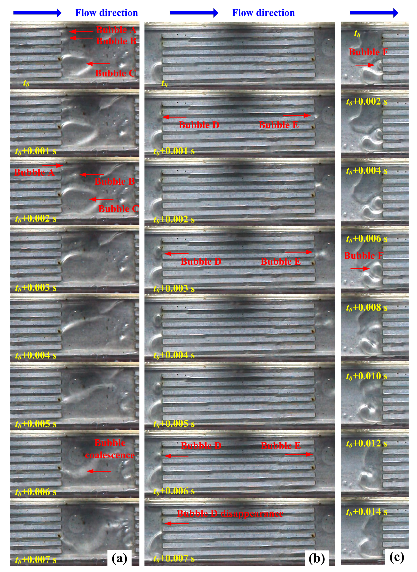
The interconnection area in the segmented heat sink provides space for bubble growth which can relieve the vapor blockage in the upstream and reduce the maldistribution in the downstream [28]. Moreover, the bubble coalescence and suction also occur due to the variation of section between the interconnection area and the microchannels. For these reasons, the segmented structure results in a smaller pressure drop comparing to the continuous heat sink. To illustrate the bubble dynamics, flow visualization at different times is carried out using a high-speed camera. Figure 10 presents the effect of the interconnection area on the flow regime with the mass flux of 80.48 kg m−2 s−1 and the effective heat flux of 158.3 kW m−2. As shown in Figure 10a, a big bubble (Bubble C) and two small bubbles (Bubble A and B) from different channels merge in the interconnection area within 0.007 s. Similarly, the bubbles of backflow also merge in the interconnection area upstream, as shown in Figure 10c. It can be found that the inverse Bubble F increases gradually from t to t + 0.008 s and then merges together with a big bubble already existed in the interconnection area. This mechanism effectively suppresses the further inverse flow. Another mechanism to suppress the inverse flow can be found in Figure 10b. The Bubble D and E occur in the same channel but are distributed at both ends. From t to t + 0.004 s, Bubble D enlarges obviously as inverse flow. However, after t + 0.004 s, Bubble E enters the interconnection area from the channel. A sudden increase in the space decreases the pressure of Bubble E which makes Bubble D go back into the channel by suction.
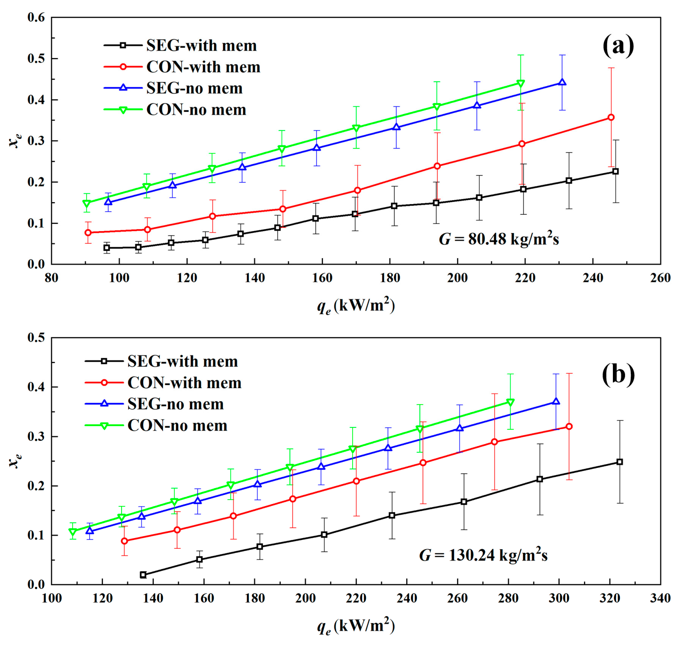
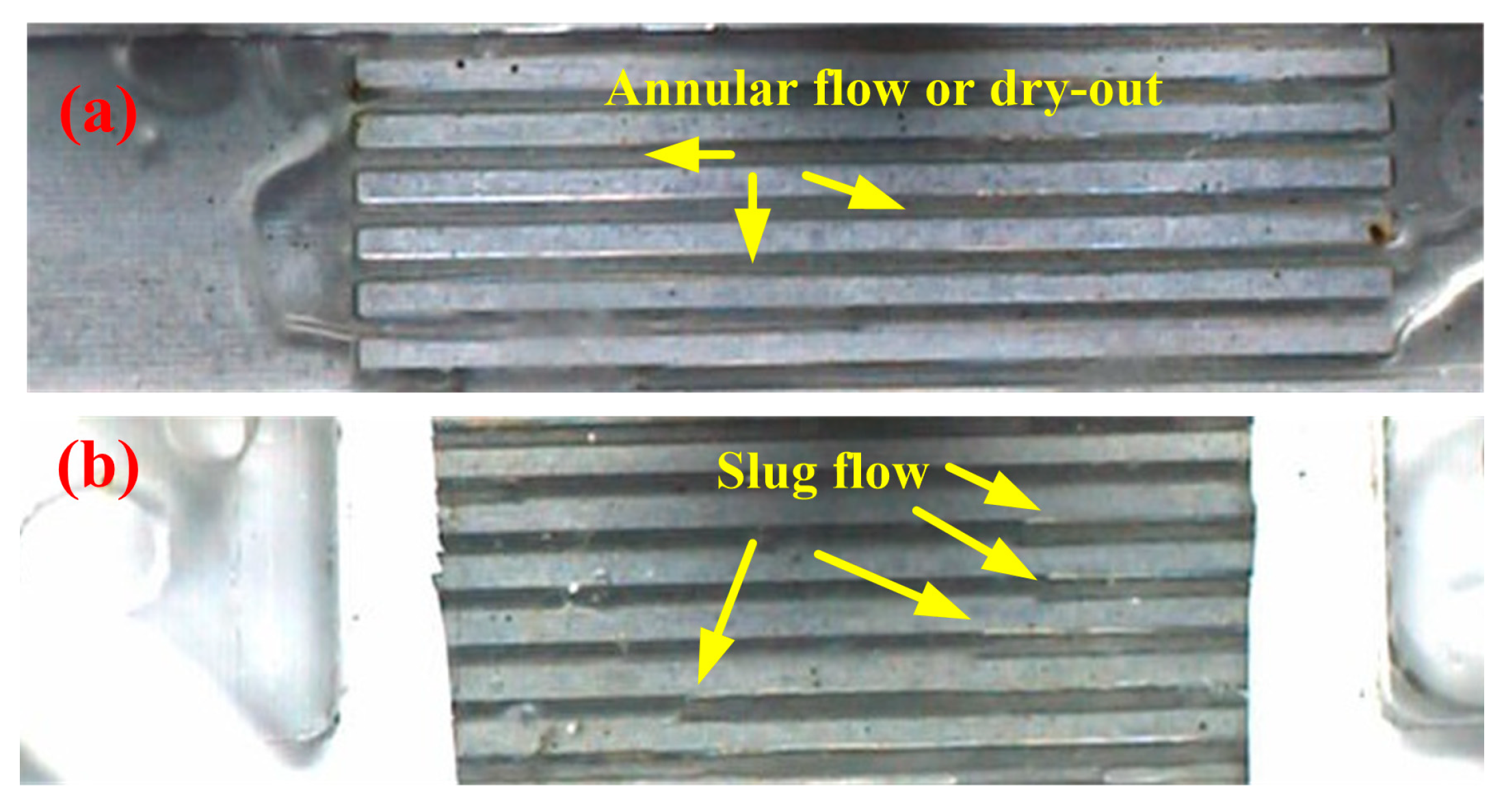
The main reason behind the increased pressure drops with the growth of heat flux is the rising vapor quality, as shown in Figure 11. Note that without the membranes, the exit vapor qualities are linearly related to the effective heat flux due to Equation (12). The liquid water vaporizes continuously to increase the vapor content which can enhance the shear stress between the liquid and vapor. Meanwhile, the occupied space by vapor increases the liquid phase velocity which causes additional frictional resistance. As a whole, the predominance of liquid phase in the frictional resistance is weakened, but the total pressure drop is increased with the growth of heat flux. When the venting membranes are used, the exit vapor quality can be reduced significantly under the same effective heat flux by discharging the vapor in microchannels in a timely manner. The interconnection area is also beneficial for the vapor venting due to the bubble coalescence which may increase the vapor pressure and quantity. Due to the non-transparency of the PTFE membrane, the combined action of interconnection area and the vapor venting membrane cannot be observed directly. To illustrate this point, two videos under the same effective heat flux of 181 kW m−2 and mass flux of 80.48 kg m−2 s−1 are recorded, which are supported as Supplementary Materials. It can be seen that the vapor quality downstream with the membrane decreases significantly, comparing to the case without membrane. As a footnote, one frame from each video is selected for comparison, as shown in Figure 12. In the case with venting membrane, the slug flow can be observed clearly in the channels, with different bubble lengths. Although it is difficult to separate the annular flow and dry-out in the image of Figure 12a, one thing is certain: the vapor venting membrane results in the variation of flow patterns which can delay the dry-out and CHF points.
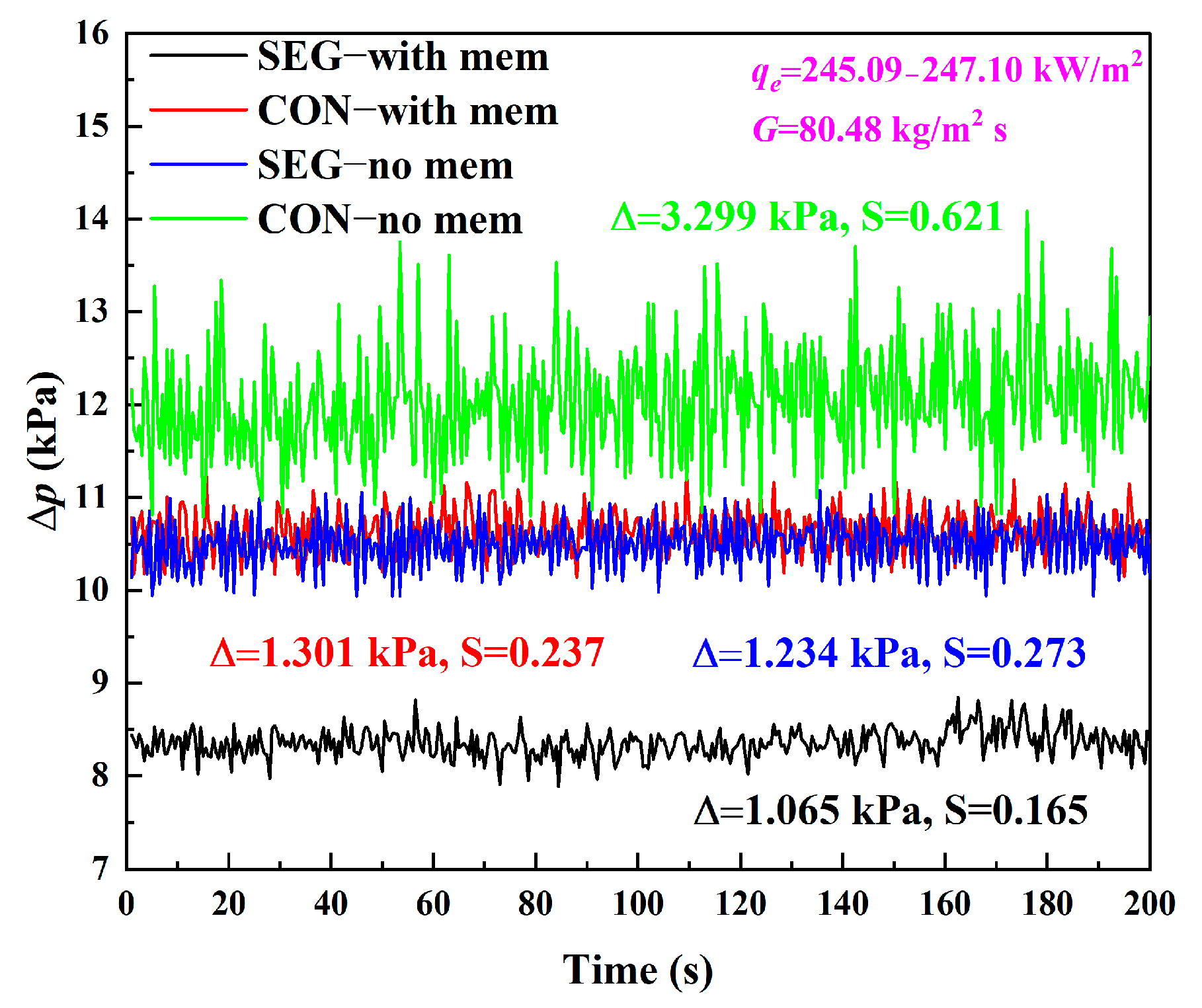
The changes of pressure drop over time with the mass flux of 80.48 kg m−2 s−1 in the continuous and segmented heat sinks are shown in Figure 13. Due to the bubble growth and deformation, the pressure drop fluctuation in a single microchannel or parallel microchannels tends to be periodic [41,42,43,44]. However, the irregular fluctuations in heat sinks are more common in the multichannel heat sink because of the maldistribution and unsynchronized two-phase flows in parallel channels [28]. The interconnection as a bumper can reduce the flow fluctuation to some extent. Furthermore, the two-phase flow instability is inhibited effectively and accompanied by the vapor venting process.

4.2. Heat Transfer Characteristics

Figure 14 shows the two-phase heat transfer coefficients at two different mass fluxes with and without the membranes. It can be found that the two-phase heat transfer coefficients in the membrane-used heat sinks are higher than those without a vapor venting membrane, which verifies that the vapor venting membrane can enhance the boiling heat transfer. In the study of David et al. [25], they observed that the venting device is ineffective in the case of low mass flux of 102 kg m−2 s−1. They believe that for the lower mass flux, stratified flow is dominant, which is not beneficial for the heat transfer, comparing with annular flow. In their study, the continuous channels are used and covered totally by the membranes which may occur easily the stratified flow. In our design, the membrane is just used in the interconnection area to reduce the super hydrophobic interaction. Meanwhile, the interconnection area can play a role to destabilize the stratified flow. Therefore, the heat transfer enhancement of vapor venting membrane can also be found even at the mass flux of 80.48 kg m−2 s−1 in our experiment.
The decrease in the heat transfer coefficient with the effective heat flux and the enhancement by the vapor venting membrane can be explained based on the boiling mechanism. Qu and Mudawar [45] confirmed that the forced convection boiling is the dominant mechanism for the saturated region in the microchannel heat sink, which is also observed in our experiment. Under forced convection boiling, the heat transfer is mainly realized by single-phase convection through the annular liquid film and the evaporation at the liquid-vapor interface so that the heat transfer coefficient is sensitive to the high vapor quality, which may result in an intermittent dry-out in the heat sink. The dry-out can significantly reduce the heat transfer coefficient due to the contact between the vapor and the wall of channels. On the other hand, the vapor venting membrane can enhance the heat transfer via vapor removal to reduce the exit vapor quality, as shown in Figure 11.
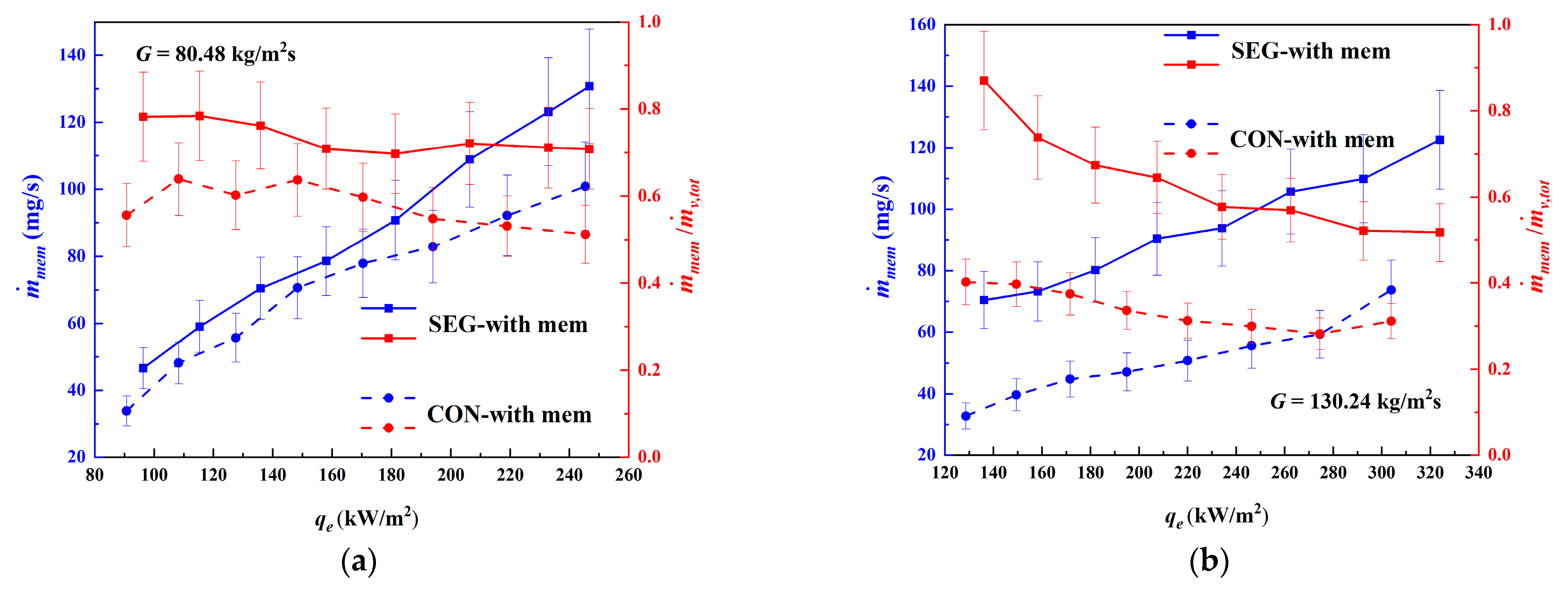
Figure 15 shows the vapor removals under different cases. The mass flow-rates of vapor removal through the membranes are increased with the increase in effective heat flux. The increase in vapor quantity and the differential pressure on both sides of the membrane are beneficial for the vapor removals, especially in the segmented heat sink. However, the percentage of vapor through the membrane in the total generated vapor is reduced when the heat input increases. The reason is not investigated in this study but a possible explanation would be given here for discussion. The vapor discharged from the membrane needs a movement perpendicular to the mainstream direction. As mentioned above, however, the velocity of the liquid phase in the channels is increased due to the space occupation by vapor. The accelerated liquid phase may easily carry the vapor bubble downstream. The inconsistency of motion direction may cause the proportion decrease in discharged vapor in the total generated vapor.

4.3. Discussion

The performance of porous membrane is a key factor for the vapor venting technique. A close investigation on the membrane permeability is presented in Figure 16, which compares the data proposed in the literature. For all cases tested in this study, the membrane permeability ranges from 2.63 × 10⁻¹⁴ m2 to 3.93 × 10⁻¹⁴ m2 which is calculated based on Equation (13). Our value is 3 to 6 times as large as those in the reference. For example, the averaged membrane permeability is 0.91 × 10⁻¹⁵ m2 in the study of Mohiuddin et al. [27] and 0.65 × 10⁻¹⁵ m2 in David et al. [25]. The source of membrane used in our experiment differs from the literature which leads to the variation of membrane parameters. However, another distinction may be more important: that two air blowers are used to purge the upper surface of the membrane to avoid the condensation in our experiment. The discharged vapor may condense on the surface of the membrane due to the temperature reduction. The condensation water effectively stops the process of vapor venting [25,46]. One of the methods to avoid the condensation is to maintain the temperature of the membrane over the saturation temperature by suitable insulation and a large contact area. The air purge should be another alternative to maintain or improve the device performance. This operation may decrease the saturation outside of the membrane and form a certain vacuum degree, which are beneficial for the vapor transport across membrane.
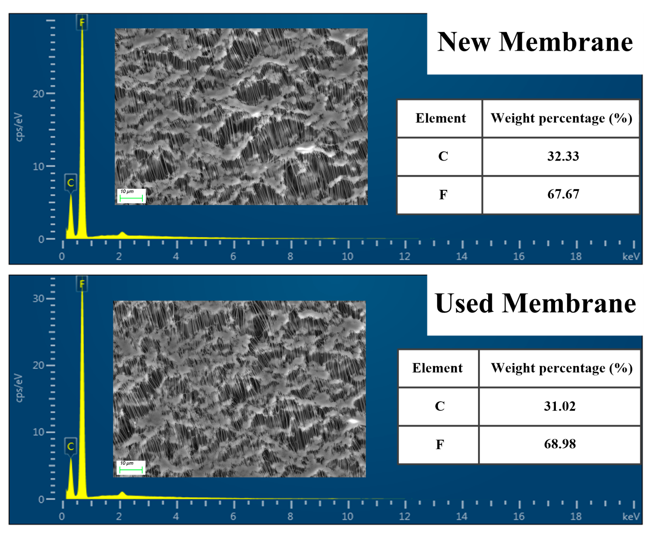
Another practical issue which is important in the use of vapor venting membranes in the two-phase heat sink is the membrane durability, such as the fouling and material degeneration. The introduction of vapor venting membranes may bring some additional costs if they have a limited lifespan. As shown in Figure 16, the membrane permeability has no obvious change during the entire process of experiment. For further confirmation, the SEM images of the membranes before and after the experiments of more than a week are carried out, as well as the energy spectrum by EDS (Energy Dispersive Spectrometer). As shown in Figure 17, there are no obvious contaminants on the surface of used membrane, and the net structure is still visible without destruction. The EDS analysis also ascertains that the chemical compositions of membrane remain unchanged after the experiments, and no other impurities are detectable. Therefore, the membrane durability can be guaranteed under appropriate operating conditions.
Furthermore, it must be admitted that although the PTFE membrane is beneficial for the vapor venting, the heat transfer may be reduced to a certain extent due to the poorer heat conductivity coefficient of organic matter than the metal material. Owing to the use of vapor venting membrane, the heating mode of liquid in the channels is changed from four-sides to almost three-sides. Therefore, how to reduce the usage of membrane but maintain the vapor venting performance is a serious problem in the actual application of this technique. For example, the membrane-covered area could be adjusted according to the subcooled length of channels under general operational conditions to replace the full coverage which is usually adopted in the literature. In this study, we try to combine the vapor venting membrane and the topology structure of heat sink so that the membrane is just used upon the interconnection area. We believe that the integrated optimization considering the structure of channels and the surface area of venting membrane could improve the performance of venting device and entire heat sink further, which is also one of research directions in our future work. On the other hand, the membrane covered on the channels is flexible and transformable, which can be ballooned slightly and then augment the space of the interconnected area. The effect of membrane deformation on the pressure drop and heat transfer characteristics should be further clarified as a scope in the following work.

5. Conclusions

In this paper, an experimental study has been performed in continuous and segmented microchannels to investigate the effect of microchannel structures on the flow boiling characteristics and vapor venting performance under different effective heat and mass fluxes. The porous hydrophobic PTFE membrane is used for discharging the vapor generated in the channels. Main conclusions are summarized as follows:
The interconnection area provides a space for bubble growth and coalescence. Meanwhile, the phenomenon of bubble suction is observed in the experiment which can suppress the inversed flow. These mechanisms prove that the segmented structure can reduce the pressure drop of two-phase flow by changing the flow regime, comparing to the continuous heat sink.
The porous hydrophobic PTFE membrane can reduce the pressure drop and increase the heat transfer coefficient under the same effective heat and mass flux. The main reason is that the vapor venting can reduce the exit vapor quality. Combining with the segmented structures, the performance of vapor venting membrane can be enhanced further due to the bubble coalescence caused in the interconnection area. The increased vapor pressure and quantity are beneficial for the vapor venting. Following the enhanced vapor discharge, the fluctuation of pressure drop is weakened which is conducive for the safe operation of heat sink.
The mass flow rates of vapor removal through the membranes are increased with the increase in effective heat flux. However, the percentage of vapor through the membrane in the total generated vapor is reduced when the heat input increases. The air purge is a proven and useful method to maintain or improve the vapor venting device performance.
The present study illustrates that the segmented structure of heat sink may improve the performance of a vapor venting device. This attempt is just a starting point and the joint-optimization considering the microchannel structure and vapor venting should be investigated more deeply to provide feasible solutions for the design of high-performance heat sink.

Supplementary Materials

The following supporting information can be downloaded at: https://www.mdpi.com/article/10.3390/en15228756/s1, Video S1: Segmented channels with membrane.mp4; Video S2: Segmented channels without membrane.mp4.

Author Contributions

Conceptualization, M.W.; methodology, M.W.; validation, M.W. and S.L.; investigation, S.L.; resources, M.W.; data curation, M.W. and S.L.; writing—original draft preparation, M.W. and S.L.; writing—review and editing, M.W.; visualization, S.L.; supervision, M.W.; funding acquisition, M.W. All authors have read and agreed to the published version of the manuscript.

Funding

This research was funded by Natural Science Foundation of Shandong Province, grant number: ZR2019BEE012.

Data Availability Statement

Data sharing not applicable.

Conflicts of Interest

The authors declare no conflict of interest.

References

  1. Tuckerman, D.B.; Pease, R.F.W. High-performance heat sinking for VLSI. IEEE Electron Device Lett. 1981, 2, 126–129. [Google Scholar] [CrossRef]
  2. Mao, N.; Zhuang, J.; He, T.; Song, M. A critical review on measures to suppress flow boiling instabilities in microchannels. Heat Mass Transf. 2021, 57, 889–910. [Google Scholar] [CrossRef]
  3. Lee, H.; Liu, D.; Yao, S. Flow instability of evaporative micro-channels. Int. J. Heat Mass Transf. 2010, 53, 1740–1749. [Google Scholar] [CrossRef]
  4. Kingston, T.A.; Weibel, J.A.; Garimella, S.V. High-frequency thermal-fluidic characterization of dynamic microchannel flow boiling instabilities: Part 1—Rapid-bubble-growth instability at the onset of boiling. Int. J. Multiph. Flow 2018, 106, 179–188. [Google Scholar] [CrossRef] [Green Version]
  5. Law, M.; Lee, P.S. A comparative study of experimental flow boiling heat transfer and pressure characteristics in straight and oblique-finned microchannels. Int. J. Heat Mass Transf. 2015, 85, 797–810. [Google Scholar] [CrossRef]
  6. Prajapati, Y.K.; Pathak, M.; Khan, M.K. A comparative study of flow boiling heat transfer in three different configurations of microchannels. Int. J. Heat Mass Transf. 2015, 85, 711–722. [Google Scholar] [CrossRef]
  7. Li, W.; Yang, F.; Alam, T.; Qu, X.; Peng, B.; Khan, J.; Li, C. Enhanced flow boiling in microchannels using auxiliary channels and multiple micronozzles (I): Characterizations of flow boiling heat transfer. Int. J. Heat Mass Transf. 2018, 116, 208–217. [Google Scholar] [CrossRef]
  8. Ma, J.; Li, W.; Ren, C.; Khan, J.A.; Li, C. Realizing highly coordinated, rapid and sustainable nucleate boiling in microchannels on HFE-7100. Int. J. Heat Mass Transf. 2019, 133, 1219–1229. [Google Scholar] [CrossRef]
  9. Sitar, A.; Golobic, I. Effect of nucleation cavities on enhanced boiling heat transfer in microchannels. Nanoscale Microscale Thermophys. Eng. 2016, 20, 33–50. [Google Scholar] [CrossRef]
  10. Deng, D.; Xie, Y.; Huang, Q.; Wan, W. On the flow boiling enhancement in interconnected reentrant microchannels. Int. J. Heat Mass Transf. 2017, 108, 453–467. [Google Scholar] [CrossRef]
  11. Deng, D.; Chen, L.; Wan, W.; Fu, T.; Huang, X. Flow boiling performance in pin fin- interconnected reentrant microchannels heat sink in different operational conditions. Appl. Therm. Eng. 2019, 150, 1260–1272. [Google Scholar] [CrossRef]
  12. Liu, T.; Li, P.; Liu, C.; Gau, C. Boiling flow characteristics in microchannels with very hydrophobic surface to superhydrophilic surface. Int. J. Heat Mass Transf. 2011, 54, 126–134. [Google Scholar] [CrossRef]
  13. Morshed, A.; Yang, F.; Ali, M.Y.; Khan, J.A.; Li, C. Enhanced flow boiling in a microchannel with integration of nanowires. Appl. Therm. Eng. 2012, 32, 68–75. [Google Scholar] [CrossRef]
  14. Li, D.; Wu, G.; Wang, W.; Wang, Y.; Liu, D.; Zhang, D.; Chen, Y.; Peterson, G.; Yang, R. Enhancing flow boiling heat transfer in microchannels for thermal management with monolithically-integrated silicon nanowires. Nano Lett. 2012, 12, 385–3390. [Google Scholar] [CrossRef] [PubMed]
  15. Wu, X.; Wu, H.; Cheng, P. Pressure drop and heat transfer of Al2O3-H2O nanofluids through silicon microchannels. J. Micromech. Microeng. 2009, 19, 105020. [Google Scholar] [CrossRef]
  16. Xu, L.; Xu, J. Nanofluid stabilizes and enhances convective boiling heat transfer in a single microchannel. Int. J. Heat Mass Transf. 2012, 55, 5673–5686. [Google Scholar] [CrossRef]
  17. Hassan, M.; El-Zahar, E.R.; Khan, S.U.; Rahimi-Gorji, M.; Ahmad, A. Boundary layer flow pattern of heat and mass for homogenous shear thinning hybrid-nanofluid: An experimental data base modeling. Numer. Methods Part. Differ. Equ. 2020, 37, 1234–1249. [Google Scholar] [CrossRef]
  18. Duursma, G.; Sefiane, K.; Dehaene, A.; Harmand, S.; Wang, Y. Flow and heat transfer of single-and two-phase boiling of nanofluids in microchannels. Heat Transf. Eng. 2015, 36, 1252–1265. [Google Scholar] [CrossRef]
  19. Liang, G.; Mudawar, I. Review of single-phase and twophase nanofluid heat transfer in macro-channels and micro-channels. Int. J. Heat Mass Transf. 2019, 136, 324–354. [Google Scholar] [CrossRef]
  20. Zhou, P.; Goodson, K.; Santiago, J. Vapor Escape Microchannel Heat Exchanger. U.S. Patent 699415107, 7 February 2006. [Google Scholar]
  21. Meng, D.; Kim, J.; Kim, C.J. A degassing plate with hydrophobic bubble capture and distributed venting for microfluidic devices. J. Micromech. Microeng. 2006, 16, 419–424. [Google Scholar] [CrossRef]
  22. Meng, D.; Cubaud, T.; Ho, C.M.; Kim, C.J. A methanol-tolerant gas-venting microchannel for a microdirect methanol fuel cell. J. Microelectromech. Syst. 2007, 16, 1403–1410. [Google Scholar] [CrossRef]
  23. Alexander, B.R.; Wang, E. Design of a Microbreather for Two-Phase Microchannel Heat Sinks. Nanoscale Microscale Thermophys. Eng. 2009, 13, 151–164. [Google Scholar] [CrossRef]
  24. David, M.P.; Miler, J.; Steinbrenner, J.E.; Yang, Y.; Touzelbaev, M.; Goodson, K.E. Hydraulic and Thermal Characteristics of a Vapor Venting Two-Phase Microchannel Heat Exchanger. Int. J. Heat Mass Transf. 2011, 54, 5504–5516. [Google Scholar] [CrossRef]
  25. David, M.P.; Steinbrenner, J.E.; Miler, J.; Goodson, K.E. Adiabatic and Diabatic Two-phase Venting Flow in a Microchannel. Int. J. Multiph. Flow 2011, 37, 1135–1146. [Google Scholar] [CrossRef]
  26. Salakij, S.; Liburdy, J.A.; Pence, D.V. Modeling Criteria for Extraction Regime Transitions for Microscale In-site Vapor Extraction Applications. Int. J. Heat Mass Transf. 2015, 84, 214–224. [Google Scholar] [CrossRef]
  27. Mohiuddin, A.; Loganathan, R.; Gedupudi, S. Experimental investigation of flow boiling in rectangular mini/micro-channels of different aspect ratios without and with vapour venting membrane. Appl. Therm. Eng. 2020, 168, 114837. [Google Scholar] [CrossRef]
  28. Dang, C.; Jia, L.; Peng, Q.; Yin, L.; Qi, Z. Comparative study of flow boiling heat transfer and pressure drop of HFE-7000 in continuous and segmented microchannels. Int. J. Heat Mass Transf. 2020, 148, 119038. [Google Scholar] [CrossRef]
  29. Steinke, M.E.; Kandlikar, S.G. An experimental investigation of flow boiling characteristics of water in parallel microchannels. J. Heat Transf. 2004, 126, 518–526. [Google Scholar] [CrossRef] [Green Version]
  30. Mahmoud, M.M.; Karayiannis, T.G.; Kenning, D.B.R. Surface effects in flow boiling of R134a in microtubes. Int. J. Heat Mass Transf. 2011, 54, 3334–3346. [Google Scholar] [CrossRef] [Green Version]
  31. Pike-Wilson, E.A.; Karayiannis, T.G. Flow boiling of R245fa in 1.1mm diameter stainless steel, brass and copper tubes. Exp. Therm. Fluid Sci. 2014, 59, 166–183. [Google Scholar] [CrossRef]
  32. Mirmanto, M. Heat transfer coefficient calculated using a linear pressure gradient assumption and measurement for flow boiling in microchannels. Int. J. Heat Mass Transf. 2014, 79, 269–278. [Google Scholar] [CrossRef]
  33. Wang, Y.; Sefiane, K. Effects of heat flux, vapour quality, channel hydraulic diameter on flow boiling heat transfer in variable aspect ratio micro-channels using trans-parent heating. Int. J. Heat Mass Transf. 2012, 55, 2235–2243. [Google Scholar] [CrossRef]
  34. Mathew, J.; Lee, P.S.; Wu, T.; Yap, C.R. Experimental study of flow boiling in a hybrid microchannel-microgap heat sink. Int. J. Heat Mass Transf. 2019, 135, 1167–1191. [Google Scholar] [CrossRef]
  35. Jayaramu, P.; Gedupudi, S.; Das, S.K. Influence of heating surface characteristics on flow boiling in a copper microchannel: Experimental investigation and assessment of correlations. Int. J. Heat Mass Transf. 2019, 128, 290–318. [Google Scholar] [CrossRef]
  36. Shah, R.K. A correlation for laminar hydrodynamic entry length solutions for circular and noncircular ducts. J. Fluids Eng. 1978, 100, 177–179. [Google Scholar] [CrossRef]
  37. Moffat, R.J. Describing the uncertainties in experimental results. Exp. Therm. Fluid Sci. 1988, 1, 3–17. [Google Scholar] [CrossRef] [Green Version]
  38. Kays, W.M.; London, A.L. Compact Heat Exchangers; McGraw-Hill: New York, NY, USA, 1984. [Google Scholar]
  39. Kandlikar, S.G.; Garimella, S.V.; Li, D.; Colin, S.; King, M. Heat Transfer and Fluid Flow in Minichannels and Microchannels; Elsevier: Waltham, MA, USA, 2006. [Google Scholar]
  40. Dharaiya, V.V.; Kandlikar, S.G. Numerical investigation of heat transfer in rectangular microchannels under H2 boundary condition during developing and fully developed laminar flow. ASME J. Heat Transf. 2012, 134, 020911. [Google Scholar] [CrossRef]
  41. Wu, H.; Cheng, P. Visualization and measurements of periodic boiling in silicon microchannels. Int. J. Heat Mass Transf. 2003, 46, 2603–2614. [Google Scholar] [CrossRef]
  42. Hetsroni, G.; Mosyak, A.; Pogrebnyak, E.; Segal, Z. Periodic boiling in parallel microchannels at low vapor quality. Int. J. Multiph. Flow 2006, 32, 1141–1159. [Google Scholar] [CrossRef]
  43. Wang, G.; Cheng, P. An experimental study of flow boiling instability in a single microchannel. Int. Commun. Heat Mass Transf. 2008, 35, 1229–1234. [Google Scholar] [CrossRef]
  44. Lv, Y.; Xia, G.; Cheng, L.; Ma, D. Experimental study on the pressure drop oscillation characteristics of the flow boiling instability with FC-72 in parallel rectangle microchannels. Int. Commun. Heat Mass Transf. 2019, 108, 104289. [Google Scholar] [CrossRef]
  45. Qu, W.; Mudawar, I. Flow boiling heat transfer in two-phase micro-channel heat sinks: I. Experimental investigation and assessment of correlation methods. Int. J. Heat Mass Transf. 2003, 46, 2755–2771. [Google Scholar] [CrossRef]
  46. Fang, C.; David, M.; Rogacs, A.; Goodson, K. Volume of fluid simulation of boiling two-phase flow in a vapor-venting microchannel. Front. Heat Mass Transf. 2010, 1, 013002. [Google Scholar] [CrossRef]
Figure 1. SEM image of unused PTFE membrane.
Energies 15 08756 g001
Figure 2. Images of contact angle measurement under (a) 30 °C and (b) 80 °C.
Energies 15 08756 g002
Figure 3. Static contact angle, dynamic advancing contact angle and surface roughness versus temperature for the PTFE membrane.
Energies 15 08756 g003
Figure 4. Schematic diagram of the experimental set-up.
Energies 15 08756 g004
Figure 5. Assembly diagram and photography of test module used in this study.
Energies 15 08756 g005
Figure 6. Structure of continuous and segmented heat sink (unit: mm): (a) Top view of segmented microchannel; (b) Top view of continuous microchannel; (c) Side view.
Energies 15 08756 g006
Figure 7. Prediction of heat loss for the continuous heat sink without membrane under mass flux of 80.48 kg m−2 s−1.
Energies 15 08756 g007
Figure 8. Validation study of single-phase flow in the continuous heat sink without membrane: (a) Friction factor [36,39]; (b) Nusselt number [40].
Energies 15 08756 g008
Figure 9. Pressure drops in the continuous and segmented heat sink with and without the venting membrane: (a) G = 80.48 kg m−2 s−1; (b) G = 130.24 kg m−2 s−1.
Energies 15 08756 g009
Figure 10. Effect of the interconnection area on the flow regime: (a) Bubble coalescence; (b) Bubble suction; (c) Bubble coalescence in inversed flow.
Energies 15 08756 g010
Figure 11. Pressure drops in the continuous and segmented heat sinks with and without the venting membrane: (a) G = 80.48 kg m−2 s−1; (b) G = 130.24 kg m−2 s−1.
Energies 15 08756 g011
Figure 12. Effect of vapor venting membrane on the flow regime: (a) Without membrane; (b) With membrane.
Energies 15 08756 g012
Figure 13. Pressure drop fluctuations in the continuous and segmented heat sinks with and without the venting membrane.
Energies 15 08756 g013
Figure 14. Two-phase heat transfer coefficients in the continuous and segmented heat sinks with and without the venting membrane: (a) G = 80.48 kg m−2 s−1; (b) G = 130.24 kg m−2 s−1.
Energies 15 08756 g014
Figure 15. Vapor venting characteristics of membranes in the continuous and segmented heat sinks: (a) G = 80.48 kg m−2 s−1; (b) G = 130.24 kg m−2 s−1.
Energies 15 08756 g015
Figure 16. Comparison of membrane permeability with the value reported in the literature [24,25,27].
Energies 15 08756 g016
Figure 17. SEM and EDS analysis for the new and used PTFE membranes.
Energies 15 08756 g017
Table 1. Detailed specifications of PTFE membrane used in this study as specified by the manufacturer.
MembranePore Size (μm)Porosity (%)Operating Temperature (°C)Thickness (μm)
PTFE (T050A047A)0.5078−120~26075
Table 2. Uncertainties of the measured and the derived quantities.
QuantityUncertainty
Microchannel dimension0.01 mm, 0.1–1.2%
Temperature (T)0.62 K, 0.5–0.9%
Voltage (U)1 V, 0.5–1%
Inlet mass flow-rate ( m ˙ i n )1 mL/min, 2.9–4.5%
Outlet mass flow-rate ( m ˙ o u t )0.6 g/min, 5.7–12.3%
Pressure drop (p)6.5 Pa, 0.3–2.3%
Mass flow-rate of vapor through the membrane ( m ˙ m e m )6.4–13.1%
Effective heat flux (qe)4.1–8.3%
Mass flux (G)3.1–6.9%
Single-phase Nusselt number (Nu)4.5–9.3%
Single-phase friction factor (f)6.7–18.5%
Exit quality without membrane ( x e , n o   m e m )7.2–15.2%
Exit quality with membrane ( x e , m e m )15.7–33.7%
Subcooled length ( L s u b )7.8–14.7%
Two-phase heat transfer coefficient ( h t p )4.8–9%
Publisher’s Note: MDPI stays neutral with regard to jurisdictional claims in published maps and institutional affiliations.