Article

Power System Stability Enhancement Using Robust FACTS-Based Stabilizer Designed by a Hybrid Optimization Algorithm

by
Saeed Behzadpoor
1,
Iraj Faraji Davoudkhani
2,
Almoataz Youssef Abdelaziz
3,*,
Zong Woo Geem
4 and
Junhee Hong
4,*
1
Department of Electrical Engineering, Faculty of Electrical and Computer Engineering, Technical and Vocational University (TVU), Tehran 14357-63811, Iran
2
Department of Electrical Engineering, University of Mohaghegh Ardabili, Ardabil 56199-13131, Iran
3
Faculty of Engineering and Technology, Future University in Egypt, Cairo 11835, Egypt
4
Department of Smart City & Energy, Gachon University, Seongnam 13120, Republic of Korea
*
Authors to whom correspondence should be addressed.
Energies 2022, 15(22), 8754; https://doi.org/10.3390/en15228754
Submission received: 1 October 2022 / Revised: 10 November 2022 / Accepted: 18 November 2022 / Published: 21 November 2022

Abstract

:
Improving the stability of power systems using FACT devices is an important and effective method. This paper uses a static synchronous series compensator (SSSC) installed in a power system to smooth out inter-area oscillations. A meta-heuristic optimization method is proposed to design the supplementary damping controller and its installation control channel within the SSSC. In this method, two control channels, phase and magnitude have been investigated for installing a damping controller to improve maximum stability and resistance in different operating conditions. An effective control channel has been selected. The objective function considered in this optimization method is multi-objective, using the sum of weighted coefficients method. The first function aims to minimize the control gain of the damping controller to the reduction of control cost, and the second objective function moves the critical modes to improve stability. It is defined as the minimum phase within the design constraints of the controller. A hybrid of two well-known meta-heuristic methods, the genetic algorithm (GA) and grey wolf optimizer (GWO) algorithm have been used to design this controller. The proposed method in this paper has been applied to develop a robust damping controller with an optimal control channel based on SSSC for two standard test systems of 4 and 50 IEEE machines. The results obtained from the analysis of eigenvalues and nonlinear simulation of the power system study show the improvement in the stability of the power system as well as the robust performance of the damping in the phase control channel.

1. Introduction

1.1. Motivations

One of the critical problems that power system operators face is the mitigation of inter-area oscillations [1]. With the advent of large-stressed power systems and interconnections between them, low-frequency oscillations between 0.2–2 Hz may be observed in power systems. The oscillations between a generator and an electrical power plant and the remaining part of the power system are named local oscillations. Local oscillations have frequencies of between 0.8 and 2 Hz. The frequency range of inter-area oscillations is 0.2–0.8 Hz, and they happen when the generators of one area oscillate with those of other areas. Because of weak damping, inter-area oscillations are more dangerous for power system stability [2]. The inter-area oscillations may not be damped effectively and can lead to system instability. Power system stabilizers (PSSs) are widely employed for mitigating low-frequency oscillations [3]; however, in some conditions, especially for inter-area oscillations, PSSs may not provide adequate damping for the system [4]. The latest progress in the field of power electronics has made it incumbent to utilize flexible AC transmission system (FACTS) devices to solve power system problems. These devices can control the network in different conditions quickly, and this feature allows their application to improve power system stability [5]. Furthermore, FACTS devices installed in suitable locations show a considerable potential for damping inter-area oscillations [6]. Hence, FACTS devices equipped with supplementary damping controllers (SDC) are used to reduce PSS limitations [7]. The static synchronous series compensator (SSSC), as a member of the FACTS device family, can control power flow in power systems by changing its characteristics from capacitive to inductive [8]. Considering the advantages, mentioned above, the SSSC can be a suitable solution for relaxing the capacities of transmission lines and active and reactive power controls in long transmission lines by having a low cost and appropriate control capability. Similar to other FACTS devices, it is possible to damp low-frequency oscillations, especially inter-area oscillations, by using a supplementary damping controller installed in an SSSC. [9,10].

1.2. Literature Review

The SSSC-based stabilizer is more reliable and effective in damping inter-area oscillations than other FACTS-based stabilizers such as TCSC and STATCOM [11]. The flower pollination algorithm is suggested in this article for the robust tuning of a static VAR compensator to mitigate power system oscillations [12].
Two independent control channels are used to control the magnitude and phase of the voltage in voltage source converters (VSCs) [13,14]. When an SSSC stabilizer is employed to damp oscillations, it can be applied to both the magnitude and phase control channels. In a single-machine infinite bus (SMIB) power system, an SSSC-based stabilizer can be applied to the magnitude control channel [15] or to the phase control channel to improve the stability of the system [16]. Moreover, in the case of a multimachine power system, one can use an SSSC-based stabilizer on the magnitude control channel to damp electromechanical oscillations [17]. Many methods have been presented in the literature for designing stabilizer parameters. Conventional methods for tuning the controller, such as the relocation of poles [18], phase compensation [19], quadratic mathematical programming [13], fuzzy logic [20], and modern control methods, have been proposed in the studies thus far [21]. The disadvantages of most of these methods are their complexity and computational burden with a high volume of calculations, low convergence speeds, and the possibility of reaching local solutions. Today, some intelligent methods, including meta-heuristic methods, such particle swarm optimization(PSO) [22], real coded genetic algorithm (RCGA) [23], differential Evolution-Pattern Search(DE-PS) algorithm [24], gravitational search optimization (GSA) Algorithm [25,26], seeker optimization algorithm(SOA) [27], evolutionary differential(ED) algorithm [9], shuffled frog-leaping Algorithm(SFLA) [28], Ant Colony Optimization Algorithm extended to real-variable optimization (ACOr) [29] and hybrid particle swarm and bacteria foraging algorithm(hPSO-BFO) [30], have been widely employed for a SSSC-based stabilizer design in order to reduce the available problems in classic design methods.
In [31], a new optimization method based on genetic algorithm is used to coordinate a SSSC based stabilizer and a PSS to improve stability of a power system. A coordinated controller for SSSC and PSS considering time delay in remote signals is presented in [32] and a new hybrid particle swarm optimization and gravitation search algorithm is used to find the stabilizer parameters. In [33,34], a multi-input single output (MISO) controller has been proposed as a SSSC-based stabilizer to improve stability of a power system. In [35], a optimization method based on genetic algorithm is presented to the tuning parameters of a lead-lag SSSC-based stabilizer to improve stability of a power system has been proposed.
In references [36,37], deep learning has been used in power system applications and the mitigation of inter-area oscillations. A static VAR compensator (SVC) has been used for oscillation damping, and a guided surrogate-gradient-based evolutionary strategy (GSES) based on the SVC control approach is proposed in this paper to damp the inter-regional oscillations of the power system [38]. A reinforcement learning (RL)-based power oscillation damping (POD) controller is proposed that uses thyristor-controlled series compensators (TCSC) to damp inter-area oscillations [39]. In [40], an improved neural-adaptive control scheme, based on online system identification and synchronous control, is proposed for damping low-frequency oscillations caused by wind integration in conventional power systems. In [41], a controller is added to the energy storage system (ESS) to damp the low-frequency oscillations. In [42], for the coordinated design of a static VAR compensator (SVC) and power system stabilizers (PSS), a new hybrid algorithm combining chaotic Jaya (CJaya) and sequential quadratic programming (SQP), i.e., CJaya-SQP, is used.
The GWO is the most popular optimization algorithm based on swarm intelligence, which has some suitable features, including easiness, resilience, deviation-free mechanism, and avoiding local optima. In addition, it has features of simple implementation, fewer tuning parameters, and fast convergence. Many engineering problems have used this algorithm for many problem-solving cases. The GWO algorithm has been investigated for exploration, exploitation, convergence, and crossing local minima. It has been tested on unimodal, multimodal, and multimodal with fixed dimensions and combined functions [43]. One can easily see that it gives similar results to the other distinguished meta-heuristic algorithms. The algorithm was also successfully applied to innovative tuning approaches in fuzzy control systems (CSs) [44]. Reference [45] investigated the application of the GWO in surface wave data for estimating near-surface S-wave velocity and profile parameters in surface waves. It has also been used for a subset feature selection problem [46]. The efficacy of the GWO for training multilayer perceptron (MLP) has been studied in [47]. In [48], the GWO algorithm was employed to solve the economic load dispatch problem. It was used for designing a wide-area PSS (WAPSS) [49]. It has also been used for the economical design of combined heat and power economic dispatch (CHPDE) [50]. This algorithm has been utilized for optimal reactive power dispatch [51].
In [52], the behavior of the GWO algorithm for objective functions whose optimal solution is not zero has been studied and it shows that the algorithm needs to be combined or improved. The GWO algorithm has been widely used to optimize continuous applications such as cluster analysis, engineering problems, neural network training, etc. In [53], the binary version, from which only the values 0 or 1 can be obtained, is used for discretization problems.
Moreover, it has been employed to optimize, and size distributed generations [54]. The grey wolf optimizer (GWO) determines the optimal size and location of ESSs in a distribution network to minimize the system’s total annual cost [55]. Another application of the GWO was reported in [56] for maximum power point tracking (MPPT) in wind turbines based on a doubly-fed induction generator (DFIG).

1.3. Contributions

In most research, as mentioned above, relating to the SSSC-based stabilizer, the stabilizer is applied to the magnitude control channel. In [13], using quadratic mathematical programming, parameters of an SSSC stabilizer in the two control channels for mitigating inter-area oscillations have been tuned. However, assuming that the variation in eigenvalues in the iterations is sufficiently small, this method provides good performance. Also, the stabilizer is not robust against changes in operating conditions. On the other hand, according to the no free lunch (NFL) theory [57], it can be said that there is no single accurate simulation method to solve all available optimization problems. That is, although a specific optimization algorithm may have suitable results for some given problems, it can, however, give a weak performance against some other problems. Also, the aforementioned cases are merely a part of the GWO algorithm applications in power systems and optimization problems. Comparing the GWO algorithm’s performance with other algorithms proves its superiority with much better results. However, when the current leader in this algorithm is in the local minimum, the entire group may fall into the local minimum. In this situation, access to a global minimum may not be possible.
Therefore, in this article, a new method has been proposed to overcome the problems in the above references, which are the lack of selection of the control channel and the design of the controller with high control cost, as well as different optimization methods.
In this new method, several objective functions have been considered for optimal design and the optimal selection of the best control channel (phase or magnitude) for the installation of an SSSC-based damping controller. These objective functions are, respectively, reducing the gain of the controller to reduce the control costs, the second and third objective functions of displacement of critical and unstable modes, and the fourth objective function are also considered as a constraint for designing the controller in the form of the minimum phase. These objective functions are calculated as a single objective function using the sum of weighted coefficients method. Further, to design the robust stabilizer to load changes, different operating conditions have been used simultaneously. To solve this optimization problem, the combined method of the gray wolf algorithm and the genetic algorithm (hGWO-GA) has been used. This combined method has advantages such as crossing local minima and high convergence. To show the effectiveness of the proposed method, eigenvalues analysis, and nonlinear simulations have been used on two power systems of 4 and 50 machines. By examining the results of the eigenvalue analysis, it is possible to choose a resistant control channel with low control gain and high damping.
The main contributions of this paper are summarized as follows:
  • Considering two objective functions, control cost and shifting critical modes to a desirable area simultaneously, as a multi-objective function to design an SSSC-based stabilizer to damp inter-area oscillations.
  • Determining different constraints for the stabilizer parameters to design the stabilizer in the form of minimum phase.
  • Optimal design of the robust SSSC-based stabilizer against load variations and different operating conditions.
The hGWO-GA algorithm is optimally used to determine the stabilizer parameters based on SSSC in different control channels. Also, a suitable control channel is selected for installing the damping controller with the aim of better damping and minimum control gain in the form of a minimum phase.

1.4. Paper Organization

Section 2 of the paper models the power system installed with an SSSC stabilizer. Section 3 presents the formulation of the optimization problem. In Section 4, the hybrid GWO algorithm and GA algorithm are described. Section 5 describes the application of the algorithm in SSSC-based stabilizer design. The simulation results are discussed and presented in Section 6. The conclusion is drawn in Section 7.

2. System Modeling

2.1. Multimachine Power System

Nonlinear differential algebraic equations were used to model a multimachine power system. The available known models used for system components, i.e., the generator, loads, and control system parameters, were utilized for extracting the necessary equations. Here, a two-axis model is exploited for synchronous generators [58]:
δ ˙ i = ω i ω s
ω ˙ i = ω s 2 H i ( T m i ( I d i E d i + I q i E q i ) + ( X q i X d i ) I d i I q i D i ( ω i ω s ) )
E ˙ q i = 1 τ d 0 i ( E f d i E q i + ( X d i X d i ) I d i )
E ˙ d i = 1 τ q 0 i ( E d i + ( X q i X q i ) I q i )
P e i = ( I d i E d i + I q i E q i ) + ( X q i X d i ) I d i I q i

2.2. Excitation System

In this paper, the standard IEEE type-AC4A excitation system [59] is employed for studies, as shown in Figure 1.

2.3. Structure of the Stabilizer

The structure of the proposed stabilizer for an SSSC in this paper is shown in Figure 2. Similar to the classic stabilizers, the proposed stabilizer uses two lead–lag compensators. The block diagram of this stabilizer is shown in Figure 3 [21]. In the proposed model for the stabilizer, the complex zeros are included in the stabilizer’s model [22]. The first block relates to the lagging/leading compensator, where the zeros and poles can be optimally tuned. The second block relates to the high-pass filter or washout filter to eliminate the steady-state effect [2]. Tw is the time constant of the washout filter.
Dynamic equations of the stabilizer are as below according to the block diagram of Figure 3.
X ˙ 1 = 1 T W U i n p u t 1 T W X 1
X 2 = T W X ˙ 1 = U i n p u t X 1
X ˙ 3 = X e
X ˙ e = 1 T 2 ( U i n p u t X 1 ) + 2 T X e 1 T 2 X 3
U o u t p u t = x 2 X . . 3 + x 1 X ˙ 3 + x 0 X 3 = x 2 T 2 ( U i n p u t X 1 )                                 + ( 2 x 2 T + x 1 ) X e ( x 2 T 2 + x 0 ) X 3
where x2, x1, x0 > 0 are parameters of the stabilizer, which should be optimally tuned, and T is the time constant that is considered constant in this paper.

2.4. Modeling of Static Synchronous Series Compensator (SSSC)

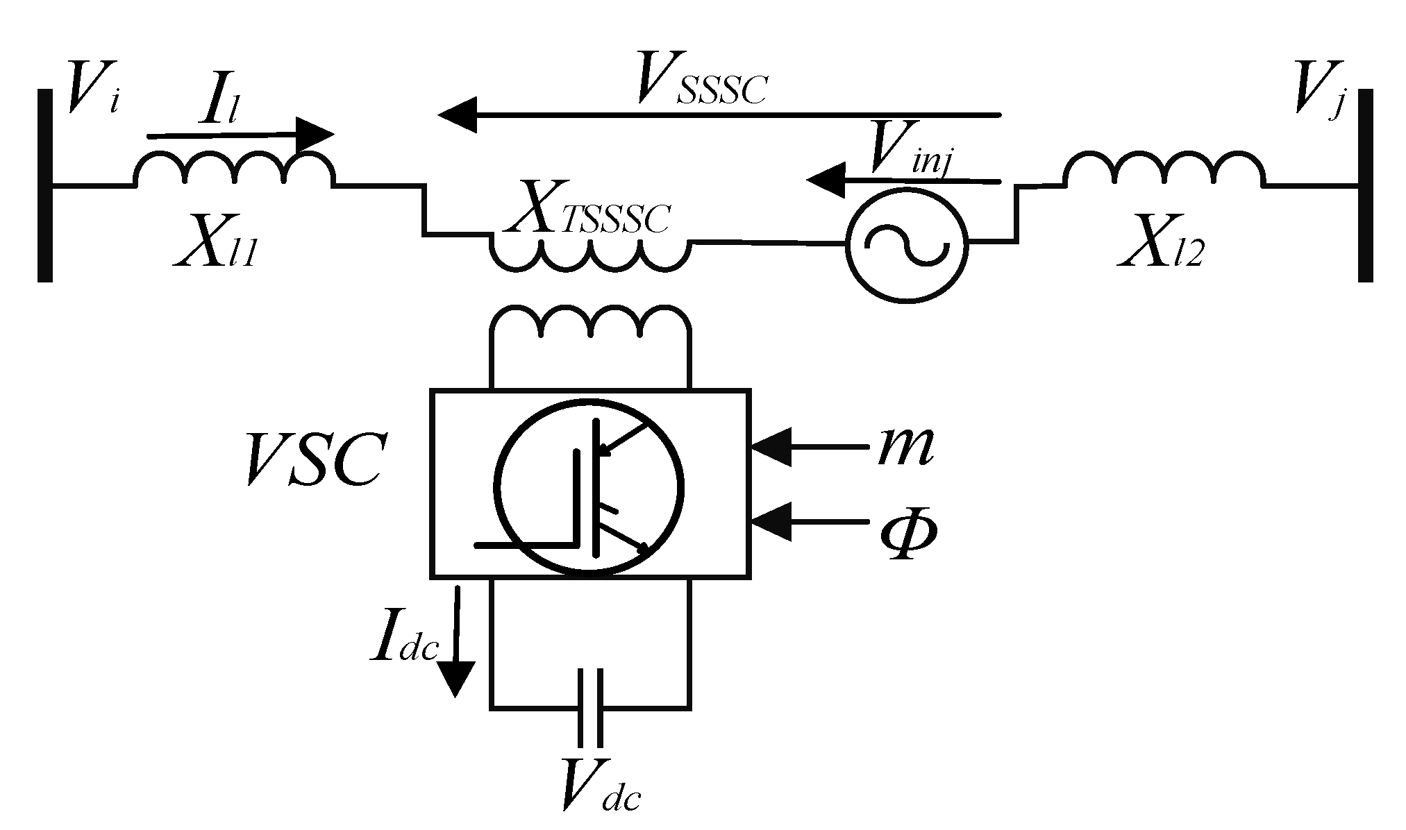
A static synchronous series compensator (SSSC), as a member of the FACTS series family, consists of a series coupling transformer (SCT) with a leakage reactance of XSCT, a voltage source converter (VSC), and a DC capacitor. Figure 4 shows an SSSC on the transmission line connecting buses i and j. The following equations describe the SSSC representation [17]:
V i n j = m k V d c ( cos ϕ + j sin ϕ )
I L = I D + j I Q = | I L | ψ
d V d c d t = m k C d c ( I D cos ϕ + I Q sin ϕ )
I ˙ D = R e X e ω s I D + ω s I Q + ω s X e ( V 1 D V 2 D V d c m k cos φ )
I ˙ Q = R e X e ω s I Q + ω s I D + ω s X e ( V 1 Q V 2 Q V d c m k sin φ )
where Vinj denotes the AC voltage provided by the SSSC device, m, and φ, respectively, show the modulation ratio and the phase given by the pulse width modulation (PWM) method, and parameter k represents the ratio between the AC and DC voltages depending on the converter structure, Vdc is the magnitude of the DC voltage; Cdc is the DC capacitance, and ID and IQ are, respectively, D- and Q components of the line current IL.

2.4.1. Phase (φ) Control Channel

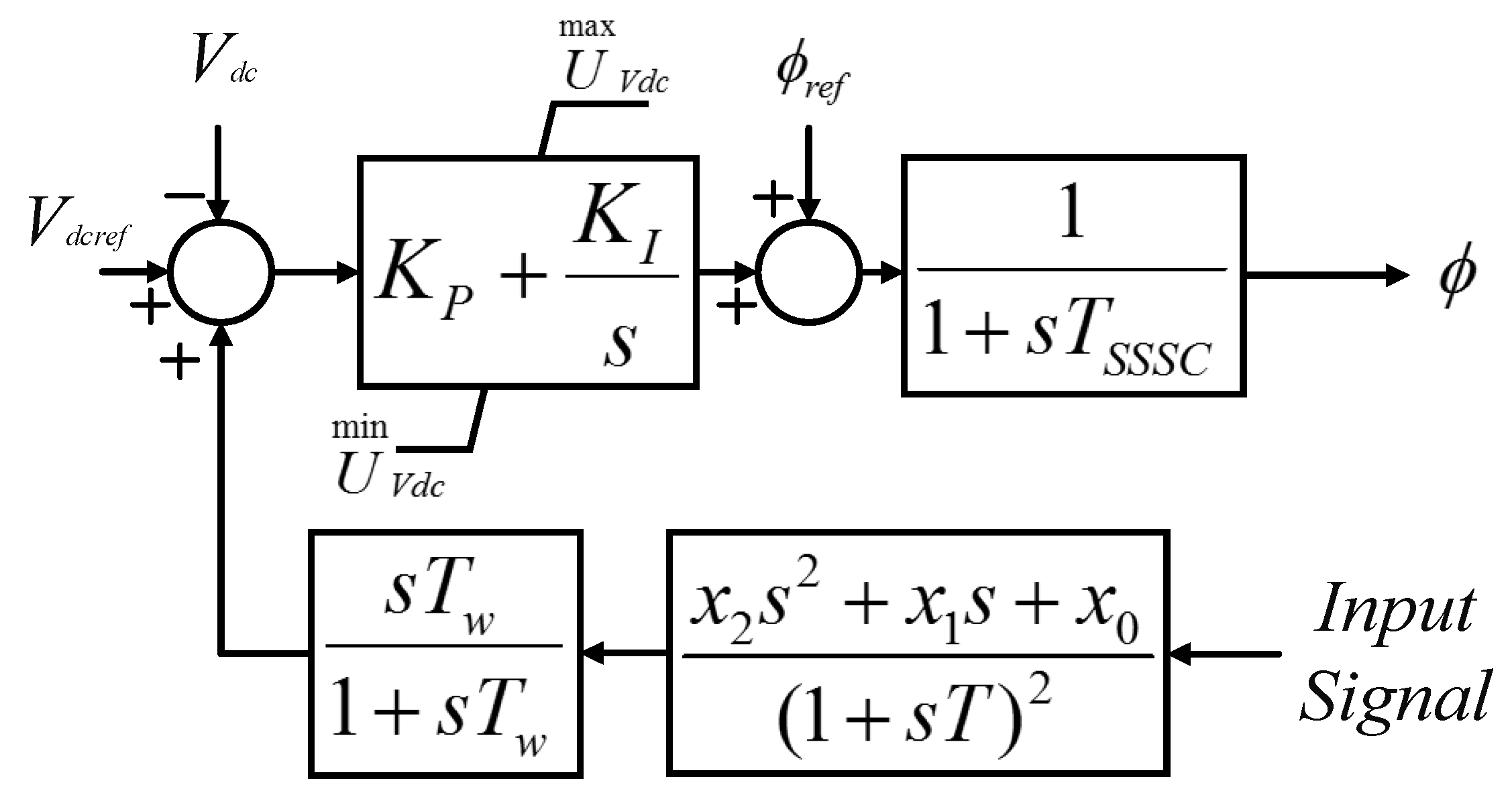
Regarding the SSSC being lossless, the AC voltage is maintained perpendicular to the line current so that the SSSC and the line only exchange reactive power. Having a lagging or leading mode with reference to the line current, the voltage of the SSSC can operate both in capacitive or inductive modes. It is considered capacitive in this paper. By phase control of the injected voltage, it is possible to utilize the SSSC in capacitive and inductive modes. This action is named the phase control channel. To maintain the injected voltage using the SSSC perpendicular to the line current, a PI controller is used in the phase controller’s loop. The block diagram of the phase control channel, including a stabilizer, is shown in Figure 5 [13].
Here, φ is the injected voltage phase for the steady-state operation conditions, and its value is taken into account below due to the capacitive mode.
φ r e f = 90 + ψ s s
φ is the line current angle in the steady-state operation conditions, TSSSC denotes the converter’s time constant, and KP and KI are coefficients of the PI controller. Also, a stabilizer is added to the phase control loop to dampen inter-area oscillations and is named a φ-based stabilizer [13]. The dynamic equations for the φ-based SSSC stabilizer are as below.
m ˙ = 1 T S S S C ( m r e f m )
φ ˙ = 1 T S S S C ( φ r e f + U φ φ )
U ˙ K I = K I ( V d c r e f V d c + U o u t p u t )
U φ = U K I + K P ( V d c r e f V d c + U o u t p u t )

2.4.2. Magnitude (m) Control Channel

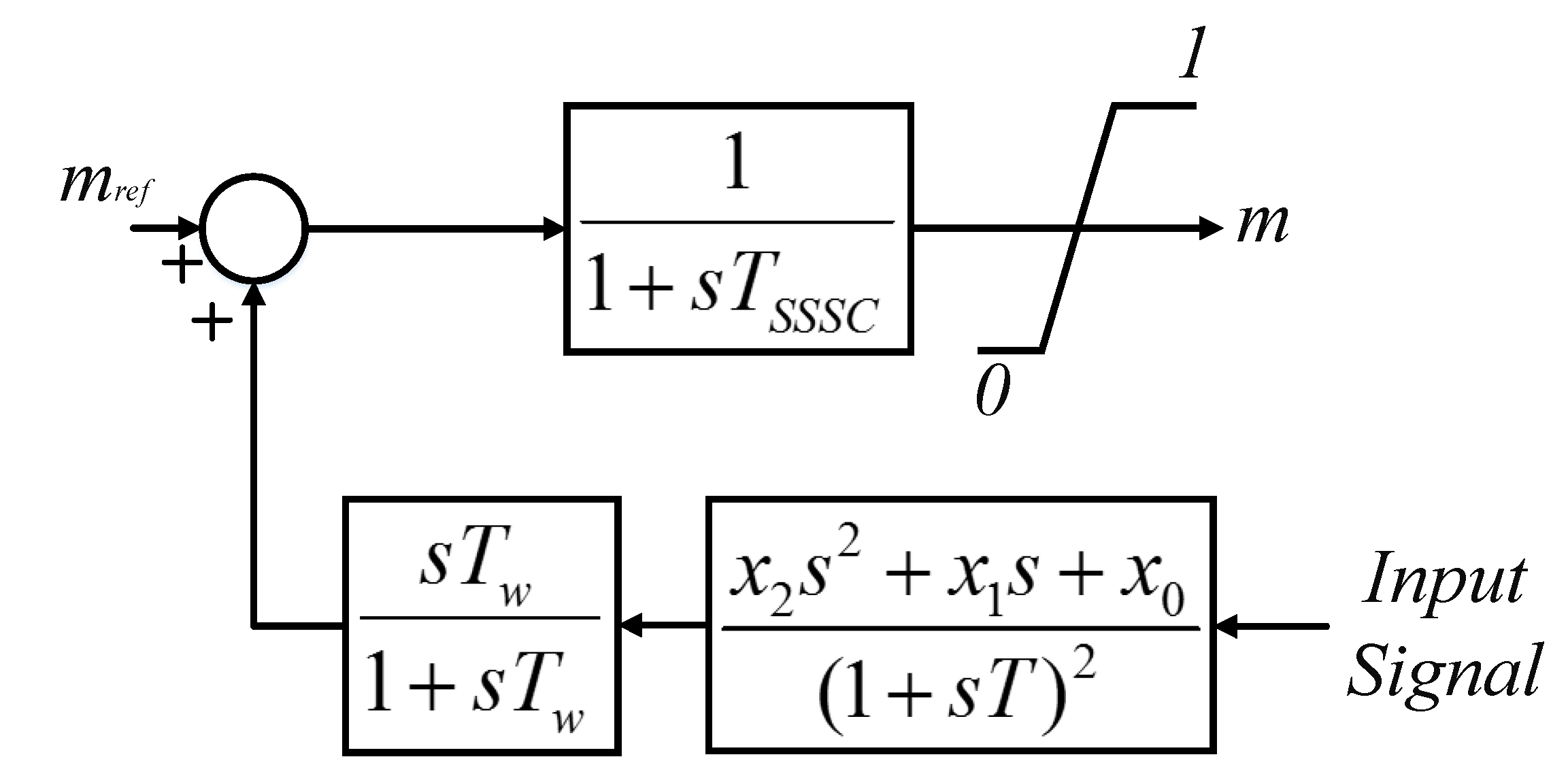
The magnitude control channel controls the magnitude of the injected voltage. In this case, the modulation coefficient of the converter is controlled, which can also control the magnitude of the voltage provided through the SSSC. In this case, it is called an m-based stabilizer [13]. Figure 6 gives the block diagram of the stabilizer discussed above.
The dynamic equations of the m-based SSSC stabilizer are as follows.
m ˙ = 1 T S S S C ( m r e f m + U o u t p u t )
φ ˙ = 1 T S S S C ( φ r e f + U φ φ )
U ˙ K I = K I ( V d c r e f V d c )
U φ = U K I + K P ( V d c r e f V d c )
In the above equations, Uoutput is the output of the stabilizer.

3. Grey Wolf Optimizer (GWO) Algorithm

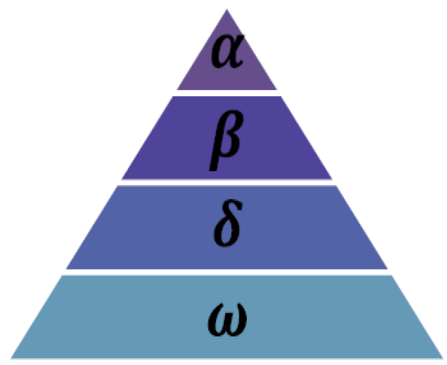
The grey wolf optimization algorithm is a novel population-based algorithm introduced in 2014 [43]. Grey wolf (Canis lupus) has its origin in the Canidae family. In particular, interest and tightening social ruling hierarchy is a prominent feature of this type of wolf, as shown in Figure 7. Several ranked wolves are in the hierarchy, which is explained as follows: the top-ranked wolves, as the leaders, are named Alphas. The main duty of the Alphas is decision-making on when to hunt, where to sleep, and when to wake up, to name but a few. The second layer of wolves in the hierarchy is named Beta. These are lower-ranking wolves and support the Alpha wolves in making decisions. The other level of wolves in the hierarchy is Omega wolves, which have the lowest rank. Omegas are sacrificing grey wolves. They are the wolves last allowed to start eating food. Provided that a given wolf is none of those mentioned above, it is named as subordinate (in some literature, it is known as Delta). Deltas must capitulate to Alpha and Beta wolves, yet they have control of Omegas. Scouts, sentinels, elders, hunters, and caretakers are categorized in the Delta group.
According to [60], the three main stages of hunting can be considered for grey wolves as tracking, chasing, and tackling the prey. Following, surrounding, and persecuting the prey to the point where its movement is terminated. That is considered as attacking the prey.
To model the social hierarchy of grey wolves at the time of designing the algorithm (GWO), the most suitable solution is assumed to be Alpha (α). As a result, the second and third finest solutions are named Beta (β) and Delta (δ), respectively. Other nominees are taken into account as Omega (ω).
Throughout the hunting stage, grey wolves surround the prey. The descriptive equations to model the surrounding behavior are given:
D = | C . X P ( t ) X ( t ) |
X ( t + 1 ) = X P ( t ) A D
In the above equations, t denotes the current iteration, X P shows the position vector relating to the prey, A and C show the coefficient vectors, and X is the position vector of the grey wolf.
Calculations of A and C vectors are as below:
A = 2 a r 1 a
C = 2 r 2
During the iterations, we linearly decrease the components of a from 2 to 0 and r 1 ,   r 2 are assumed as random vectors in the interval of [0, 1]. Identifying the location of the prey and surrounding it are some special abilities of grey wolves. To mathematically imitate the hunting behavior of the grey wolves, it is assumed that the Alpha (as the best candidate solution), Beta, and Delta benefit from better knowledge of the possible location of the prey. Consequently, the first three best solutions achieved up to the present moment are stored. The remaining search agents (encompassing the Omegas) are obliged to improve their current positions thanks to the positions of the best search agents. The related equations are presented as follows.
D α = | C 1 X α X | ,   D β = | C 2 X φ X | ,   D δ = | C 3 X δ X |
X 1 = X α a 1 D α   , X 2 = X β a 2 D β   ,   X 3 = X δ a 3 D δ  
X ( t + 1 ) = ( X 1 + X 2 + X 3 ) / 3
The ultimate position will be a random position inside a circle defined through the positions in the search space related to Alpha, Beta, and Delta. Simply put, Alpha, Beta, and Delta make estimations for the position of the victim, and the rest of the wolves randomly improve (update) their corresponding positions on all sides of the victim [61].

4. The Proposed hGWO-GA

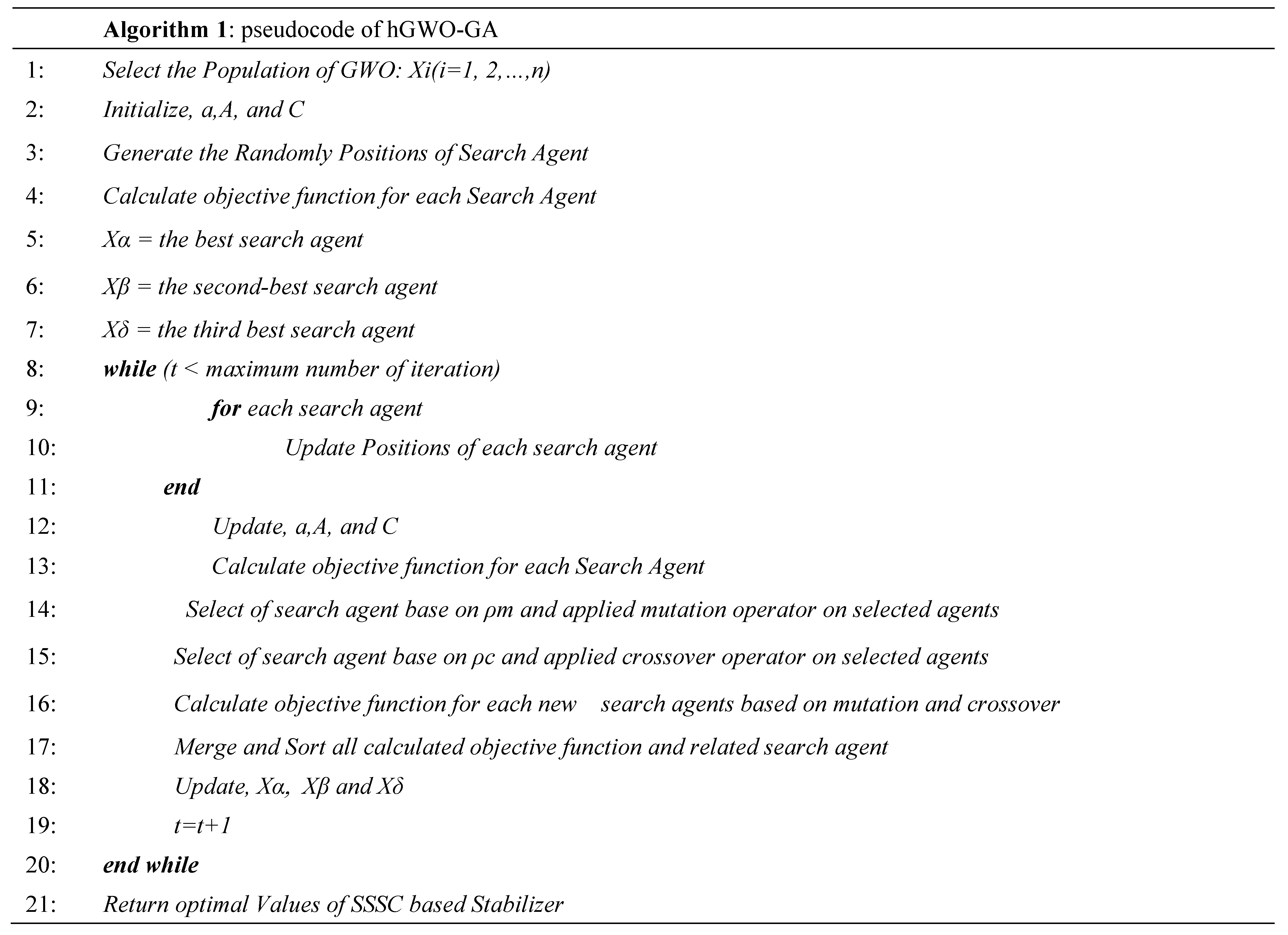
According to the description in Section 3, it has been observed that grey wolves can find the placement of prey and hunt it. However, the order of the optimum value is unknown in the search space. Therefore, it is assumed that the grey wolves update their position based on the header group to illustrate the imitation of hunting behavior in mathematical relations. When the current leader is in the local minimum, the entire group falls into the local minimum. Recently, the GWO algorithm has been combined with other optimization algorithms to eliminate this issue. In [62], the GWO is combined with a genetic algorithm to solve high-dimensional optimization problems. In this research, the population was divided into groups to ensure good coverage of the searching operation. Of course, the time of computation is increased with increasing search space. In [63], a hybrid of the GWO and PSO optimization algorithms is presented for unit commitment as an optimization problem with high dimension. In [64], a novel optimization algorithm as a hybrid of symbiotic organisms (SOS), GWO, and GA algorithm is presented. Generally, the stabilizers of the power systems have a few parameters for tuning. Therefore, increasing the search space to a level can increase computation time without significant results. In this paper, to refrain from premature convergence and being trapped in local minima, a simple hybrid of the GWO and GA algorithm is presented to find the optimum parameter of the SSSC stabilizer to damp inter-area oscillations. In the proposed method, the position of wolves is changed randomly and probably. This reduces the chance of falling into the local minimum. In this paper, to create this random path change process, the mutation and crossover method, adopted from the GA algorithm, has been used. In addition to passing the local minimum, this method accelerates the algorithm’s convergence. Additionally, if a random path change worsens the position of the wolves, it will be deleted at the next stage. The pseudocode of the proposed is shown in Figure 8.

5. Design of an SSSC-Based Stabilizer Using the hGWO-GA Algorithm

In this section, the objective function and optimization steps for designing a robust SSSC stabilizer have been expressed.

5.1. Objective Functions

(1)
The first objective function.
In the proposed work, the stabilizer’s structure is taken into account as Equation (32) [13].
f ( s ) = x 2 s 2 + x 1 s + x 0 ( 1 + s T ) 2 s T w 1 + s T w
The gain of the SSSC stabilizer is assumed as the first objective function, which can be written according to Equation (33).
F 1 = i = 1 N | f ( j ω i ) |
here ω1, ω2, …, and ωN are the frequencies in the region that the critical mode must undertake a shift.
(2)
The second and third objective functions.
The second and third objective functions are concerned with the displacement of critical modes with the least damping coefficient. The real parts of these functions are near the considered values. The functions can be expressed as Equations (34) and (35), respectively. A D-shape part for the functions on the complex s-plane is given in Figure 9 [13].
F 2 = σ i σ 0 ( σ 0 σ i ) 2
F 3 = ζ i ζ 0 ( ζ 0 ζ i ) 2
σi and ζi denote, respectively, the real part and the damping coefficient of the ith critical mode, and σ0 and ζ0 are constants where the chosen eigenvalues in the desired interval become closer to these values.

5.2. Constraints

The constraint is concerned with the parameters x0, x1, x2 > 0 related to the stabilizer. This constraint is pertinent to the stabilizer’s zeros. Considering x ^ 1 = x 1 / x 0 T , x ^ 2 = x 2 / x 0 T 2 , s ¯ = s T and substituting them in Equation (32) yields:
F ( s ¯ ) = x ^ 0 x ^ 2 s ¯ 2 + x ^ 1 s ¯ + 1 ( 1 + s ¯ ) 2 s ¯ T w 1 + s ¯ T w
There is a set of two poles at s = −1 relating to the transfer function F ( s ¯ ) . Regarding the phase-lead structure, the zeros of F ( s ¯ ) in connection with its poles are assumed to be nearly one decade closer to the origin, so their location is in the range of (−0.1, −1). Moreover, with regard to the phase-lag structure, the zeros are more or less one decade apart from the origin, meaning that they are in the range of (−10, −1). By simplifying the problem, the constraints related to the phase-lead structure can be expressed by the following relationships [65]:
x ^ 1 x ^ 2 1
x ^ 1 0.1 x ^ 2 10
x ^ 1 2 4 x ^ 2 0
By substituting x ^ 1 and x ^ 2 in Equations (37)–(39), the constraint in connection with the phase-lead structure is stated as:
T x 1 T 2 x 0 x 2 0
T x 1 10 T 2 x 0 0.1 x 2 0
4 x 2 x 0 x 1 2 0
The above equations are rewritten below to implement the impacts of the mentioned constraints on the objective function:
G 1 ( x ) = T x 1 T 2 x 0 x 2
G 2 ( x ) = T x 1 10 T 2 x 0 0.1 x 2
G 3 ( x ) = 4 x 2 x 0 x 1 2
In the same way, the equations concerning the stabilizer in the phase-lag structure will be:
G 1 ( x ) = T x 1 T 2 x 0 x 2
G 2 ( x ) = T x 1 0.1 T 2 x 0 10 x 2
G 3 ( x ) = 4 x 2 x 0 x 1 2
The abovementioned equations, as a penalty factor, are appended to the objective function:
F 4 = i = 1 3 K i G i ( x ) 2
K i is a coefficient chosen in proportion to the value of G i ( x ) , based on Equation (50):
K i = { 50           i f       G i ( x ) > 0 0                   o t h e r w i s e    

5.3. Multi-Objective Function

An objective function, given in Equation (51), combines all the functions and constrains introduced in the previous section:
M u l t i O b j e c t i v e   f u n c t i o n = i = 1 4 w i F i = w 1 F 1 + w 2 F 2 + w 3 F 3 + w 4 F 4
In the above equation, wi are constant weighting coefficients chosen experimentally based on their effects on the objective function. In the proposed work, the coefficients are set equal to 1, 5, 10, and 50, respectively.

5.4. Robust Objective Function

For robust stabilizer design, the objective function is calculated simultaneously for all different operating conditions according to the Equation (52):
R o b u s t   O b j e c t i v e   F u n c t i o n = j = 1 N P ( i = 1 4 ( w i F i j ) )
According to the hGWO-GA algorithm, the steps of designing an SSSC-based stabilizer are summarized as follows:
Step 1. Define input data of the studied power system and upper and lower boundary parameters of the SSSC-based stabilizer (xminxmax).
Step 2. Define the number of search agents (N), the maximum number of iterations (iter-max), the crossover percentage (ρc), and the mutation percentage (ρm).
Step 3. Initialize the grey wolf population matrix (X). In this matrix, each population set represents the position of a search agent. From the optimization point of view, the position of a search agent signifies one of the candidates for the minimization of the objective function. In the proposed objective function, the position of each search agent consists of the three unspecific parameters of the SSSC stabilizer (i.e., x2, x1, and x0, as shown in Figure 10). Each element of the position of the search agent is initialized within the limits of the parameters of the SSSC stabilizer and may be determined as:
x m , j = x m , j min + r a n d ( 0 , 1 ) × ( x m , j max x m , j min )
where xm,j is the jth element of the mth search agent position. Here m = 1, 2,…, N and j = 1, 2,…, D. Here, N is the maximum number of search agents and D is the number of variables in the problem (in the proposed objective function D = 3). According to the above explanations, the matrix X can be presented in the following way:
X = [ X 1 X 2 . . . X N ] = [ x 1 , 1 x 1 , 2 x 1 , 3 x 2 , 1 x 2 , 2 x 2 , 3 . . . . . . . . . x N , 1 x N , 2 x N , 3 ]
The position of each search agent should satisfy the constraints of the parameters of the SSSC stabilizer.
Step 4. Initialize a, A, and, C using (27) and (28).
Step 5. Linearize the power system installed with an SSSC-based stabilizer for each search agent, calculate the eigenvalues and determine the critical modes, then evaluate the objective function (Equation (51)) value of each search agent.
Step 6. Set the position of the search agent of matrix X corresponding to the first, second, and third values of the fitness function to Xα, Xβ, and, Xδ, respectively.
Step 7. Set iteration number iter = 1.
Step 8. Update the position of each search agent using (29)–(31).
Step 9. Update the value of a, A, and, C using (27) and (28).
Step 10. Check the limits of the parameters of the SSSC-based stabilizer.
Step 11. Check constraint limits for each search agent. If constraint limits are satisfied, then go to the next step. Otherwise, replace the search agent position with the boundaries of the search space (xminxmax).
Step 12. Linearize the power system installed with an SSSC-based stabilizer for each search agent, calculate the eigenvalues and determine the critical modes, then evaluate the objective function (Equation (51)) value of each search agent.
Step 13. Select a search agent randomly based on the crossover percentage (ρc).
Step 14. Linearize the power system installed with an SSSC-based stabilizer for selected search agents of the crossover operator, calculate the eigenvalues and determine the critical modes, then evaluate the objective function (Equation (51)).
Step 15. Select the search agents randomly based on the mutation percentage (ρm).
Step 16. Linearize the power system installed with an SSSC-based stabilizer for selected search agents of the mutation operator, calculate the eigenvalues and determine the critical modes, then evaluate the objective function (Equation (51)).
Step 17. Merge and sort all objective functions in steps 12, 14, and 16, and related search agents.
Step 18. Set the position of the search agent corresponding to the first, second, and third values of the fitness function to Xα, Xβ, and, Xδ, respectively.
Step 19. Increase the iteration number by 1, that is, iter = iter + 1.
Step 20. If the maximum number of iterations is reached, stop the iterative process and store Xα as the best solution to the optimization problem, otherwise, go to step 8.
The optimal tuning of the SSSC-based stabilizer parameters is formed as a constrained optimization problem. In this problem, the constraints are chosen as the limits of the SSSC-based stabilizer’s parameters.
Minimize ( Robust Objective Function ) = j = 1 N P ( i = 1 4 ( w i F i j ) ) subject to : x 0 , min x 0 x 0 , max x 1 , min x 1 x 1 , max x 2 , min x 2 x 2 , max
The range of the optimized parameters is considered as (0–3), the time constant of the stabilizer is assumed to be T = 0.4, and σ 0 , and ζ 0 are selected to be −0.5 and 0.1, respectively. To calculate F1, ω i = 1 , 3 , 5 are considered based on the frequency of the inter-area mode case. The values of these coefficients are determined based on each objective function’s importance and on the fact that it is a special case of an optimal Pareto solution set. After running the problem several times, calculating the objective functions, and analyzing the results of the eigenvalues, the weight coefficients are determined.
To compare the stabilizer gain ( | f ( j ω ) | ) for the channels, a reference value ω = 2     rad / s is chosen. To solve this optimization problem, the obtained parameters from the hGWO-GA, GWO, ACO, and PSO algorithms are taken into account. The parameter settings of the optimization algorithms are shown in Table 1.

6. Simulation Results

In this section, the simulation results of two power systems, namely 2-area 4-machine power systems and 2-area 50-machine power systems are studied as small and large power systems.

6.1. The IEEE 4-Machine Power System

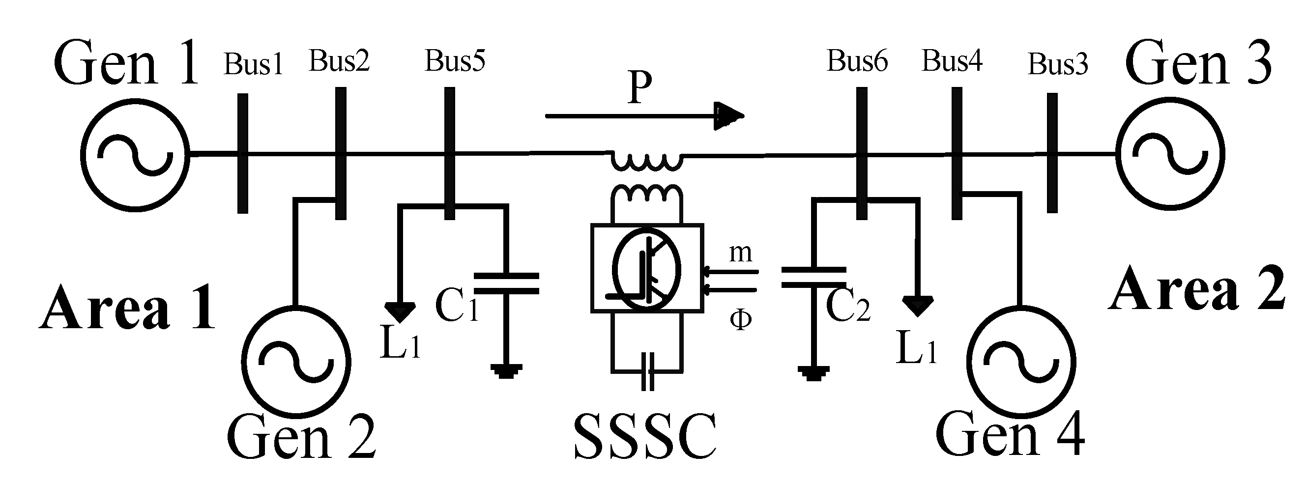
One of the studied systems in the field of power system stability is the four-machine power system of Kundur [2]. For this purpose, a two-zone four-machine system has been used in this work. Figure 10 illustrates the single-line diagram for the system under study. The system data are given in [13]; with the aim of controlling the inter-area oscillations, an SSSC is placed on the transmission line connecting buses 5 and 6. The parameters exploited for the SSSC are assumed to be TSSSC = 0.01 sec, k = 1, XSCT = 0.15 p.u, Cdc = 1 p.u., Vdcref = 1 p.u., KP = 25, and KI = 200. Loads of the system are also considered to be constant impedances.
Figure 10. Two-area four-machine power system with SSSC.
Energies 15 08754 g010
In the proposed method, two scenarios are analyzed. The first scenario is the optimal design of the stabilizer for three different operating conditions separately, and the second scenario is the robust design of the stabilizer for different operation conditions simultaneously. By changing the power transfer between the two areas on the tie lines, operational conditions are formed. To increase the amount of power transmission between the areas, the load in area 1 is modified and the amount in area 2 is increased. Table 2 lists the operating conditions for the light, normal, and heavy loading levels.
To select the input signal for the stabilizer, the residual method is used. With regard to the residuals provided in the inter-area mode for various operation situations, a signal with the maximum residual value is chosen as the feedback signal to be employed by the stabilizer. According to this method, the current flowing on the tie-line is assumed to be the input signal to the stabilizer. Table 3 lists the eigenvalues of the open-loop system, where the inter-area mode is highlighted. The results show that the damping ratio of the inter-area mode is decreased as the transferred power between the two areas increases, and it tends to be unstable at heavy loading conditions. The proposed study employs an SSSC-based stabilizer to improve the stability and increase the inter-area mode oscillation damping.

6.1.1. Optimal Design of SSSC-Based Stabilizers

In this section, the objective function of Equation (51) is used to design an SSSC-based stabilizer. The different optimization algorithms are employed separately for all operating conditions to achieve an optimal design for an SSSC-based stabilizer. For each load condition, 30 independent runs are performed for different populations. Table 4 lists the parameters of the stabilizers and the gain of the stabilizer ( | f ( j ω ) | ) at ω = 2     rad / s for various operational situations. In this table, the best solution, the worst solution, and the mean and standard deviation values of the objective function have also been shown. Moreover, Table 5 gives the inter-area mode in the closed-loop system, based on the parameters of Table 4. One can easily see from Table 5 that for both control channels, the mitigation of the inter-area mode is considerably improved. Table 4 also shows that the gain of the stabilizer in the phase control channel is less than in the magnitude control channel. Therefore, to improve the inter-area mode damping up to a suitable level, the control cost in the control phase channel is less than the magnitude control channel. In other words, the stabilizer in the phase control channel brings greater success than in the magnitude control channel. The statistical results of Table 4 show that the hGWO-GA performs better than the other methods in exploiting the global optimum and overcoming premature convergence.

6.1.2. Robust Design of the Stabilizer

The operating conditions of a power system may vary with load changes. A designed stabilizer for a certain operating condition may not be suitable for other operating conditions. In this paper, different operating conditions are simultaneously considered for the robust design of an SSSC-based stabilizer.
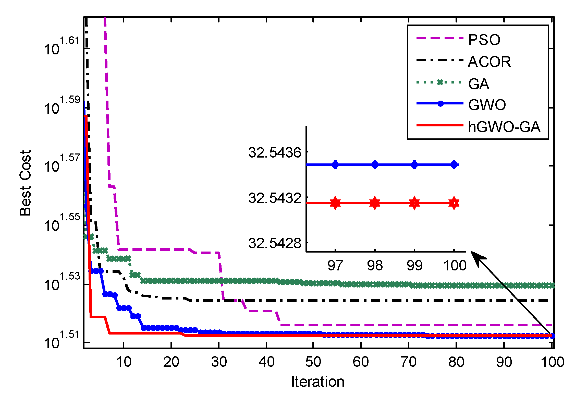
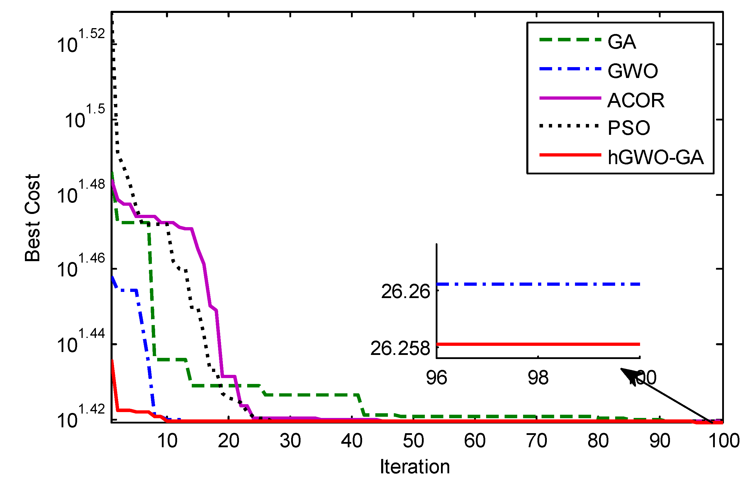
In this case, the objective function is considered as Equation (51). The parameters for the robust stabilizer in both control channels are summarized in Table 6. As is seen, the table confirms that the stabilizer’s gain in the phase control channel is less than in the magnitude control channel. Table 7 lists the eigenvalues of the inter-area mode for the closed-loop control system, based on the parameters of Table 6, for various operational situations. It is noted from the table that the inter-area mode damping in all operation situations has effectively improved. The convergence curves of different optimization algorithms are shown in Figure 11 and Figure 12 for the phase and magnitude control channels, respectively. These figures and obtained statistics results in Table 6 confirm that the hGWO-GA algorithm converges better than the other algorithms.
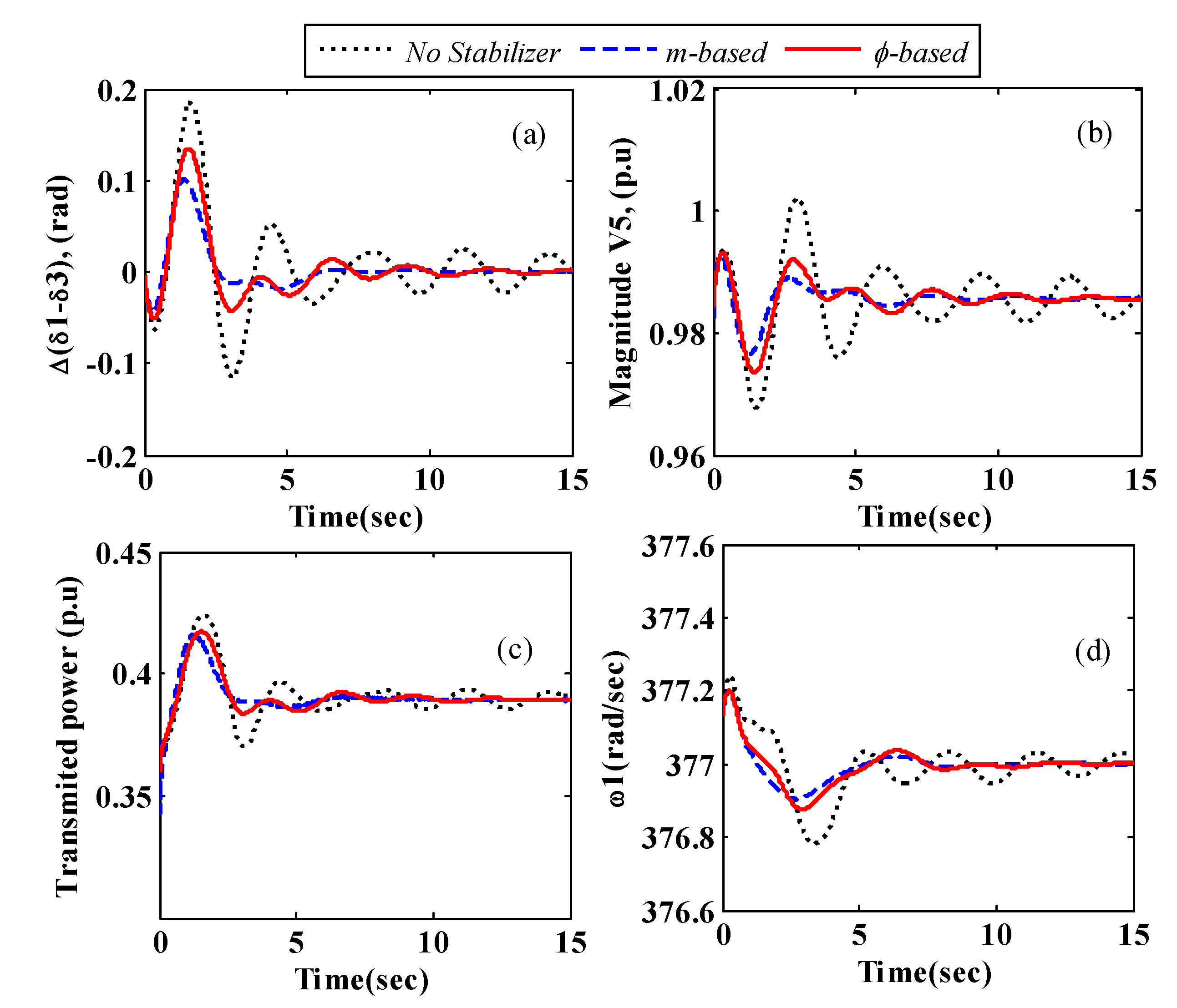
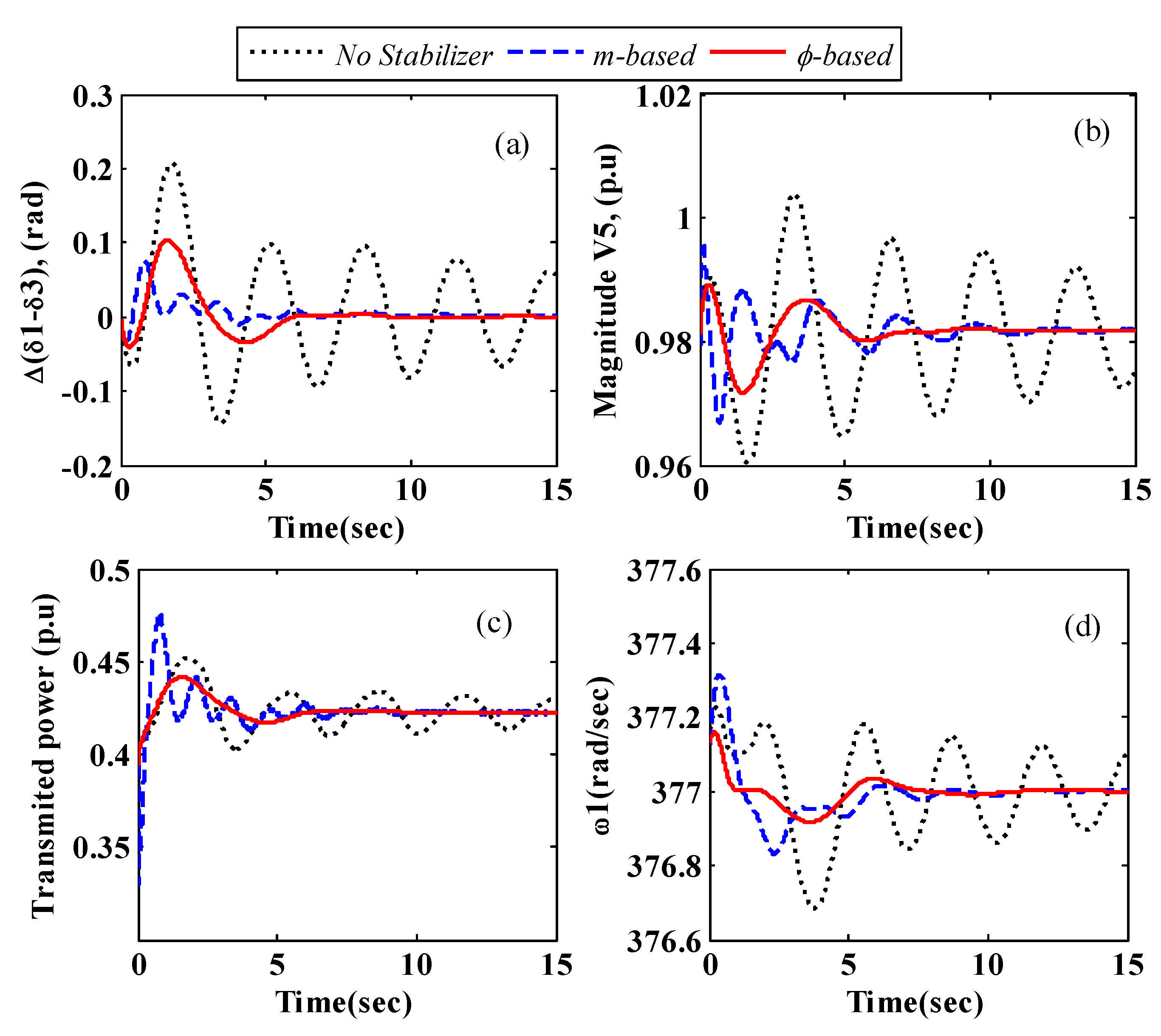
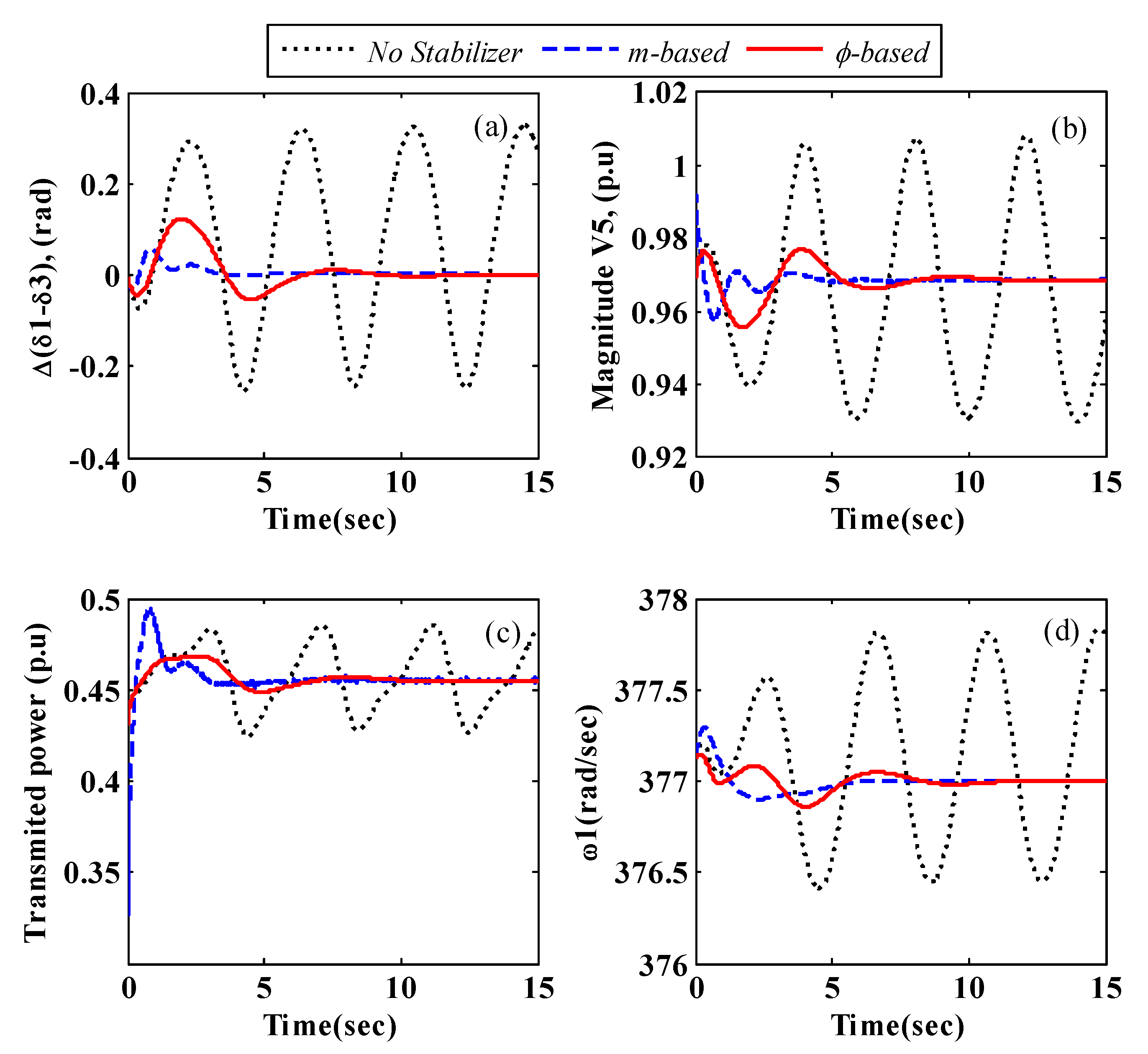
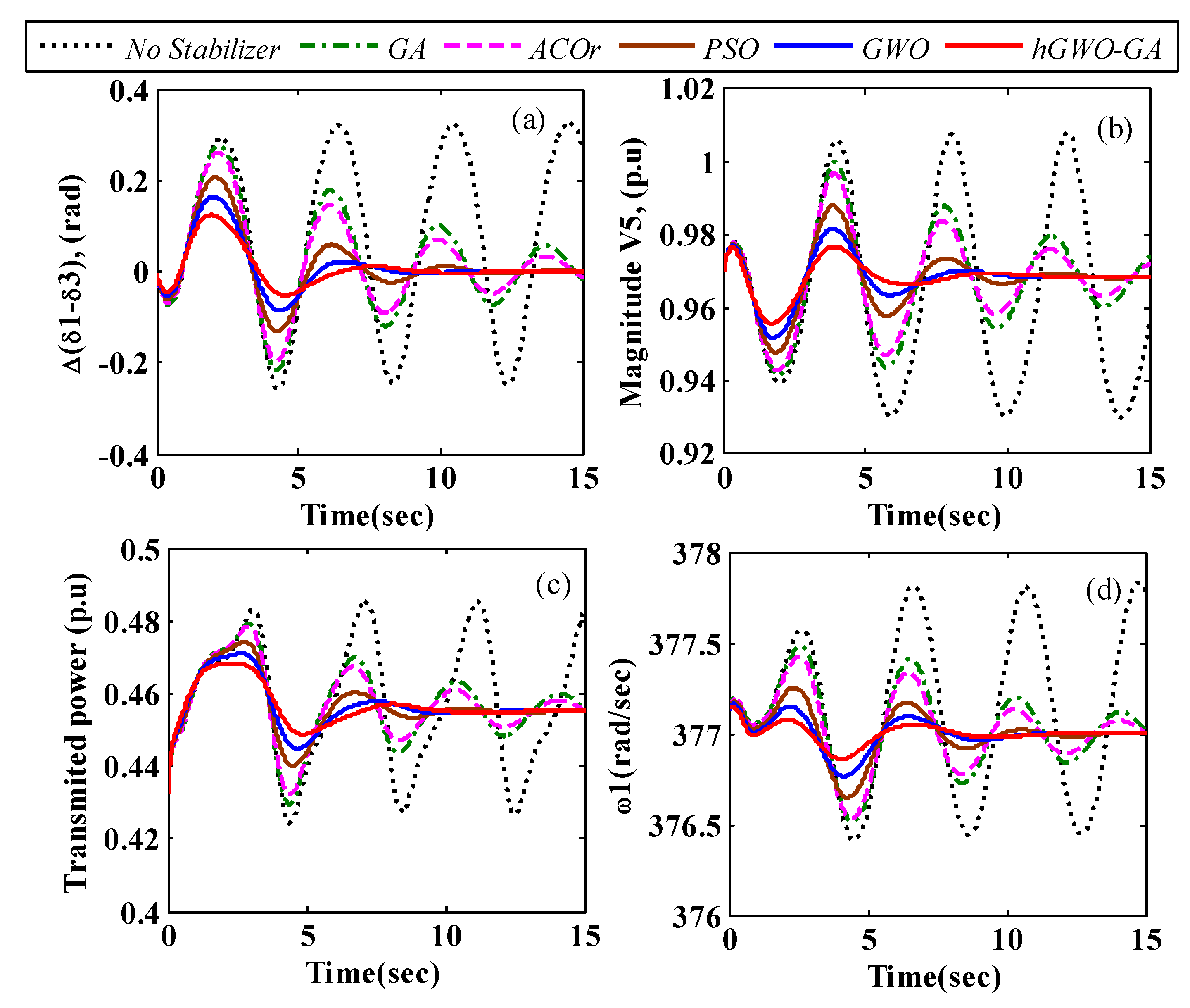
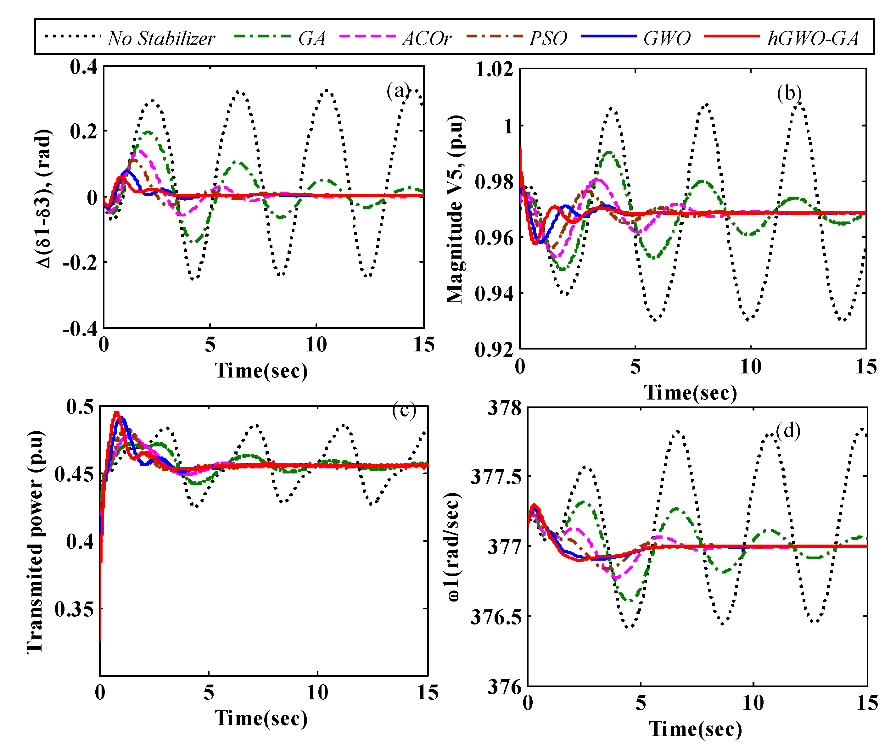
To verify the effectiveness of the proposed stabilizer design, a three-phase fault is assumed to occur on bus 6 of the system under study. Without switching any lines, the fault is cleared after 20 ms. Nonlinear simulations of the considered fault for the robust SSSC stabilizer designed by the hGWO-GA algorithm in the light, normal, and heavy load conditions, are shown in Figure 13, Figure 14 and Figure 15 respectively, for the stabilizer in both control channels. Nonlinear simulations for the robust stabilizers designed using different optimization algorithms in phase and magnitude control channels are also shown in Figure 16 and Figure 17, respectively. These figures confirm the results of the analysis of the eigenvalues. They show that the designed robust stabilizer in both control channels can effectively dampen inter-area oscillations. These figures also show that the designed stabilizer can improve the damping of other oscillations such as local modes, transmitted power, and the magnitude of voltage in buses.

6.1.3. Comparison of the Proposed Objective Function

In [66,67], the objective function is considered as a combination of only F2 and F3. The obtained parameters from different optimization algorithms for a robust SSSC-based stabilizer, in this case, are shown in Table 8. A comparison of the results in this table and the results of Table 6 show that the gain of the stabilizer ( | f ( j ω ) | ), as control cost, in this case, is bigger than that obtained by the proposed objective function. The reason for this is that in the proposed objective function, the minimization of the gain of the stabilizer is considered a part of the objective function. The inter-area mode for the closed-loop system, in this case, has been shown in Table 9. Because in this case, the focus is only on shifting the critical modes to a desirable area, the effect of the stabilizer on the damping of the inter-area oscillations is more effective than the proposed method.

6.2. IEEE 50-Machine Power System

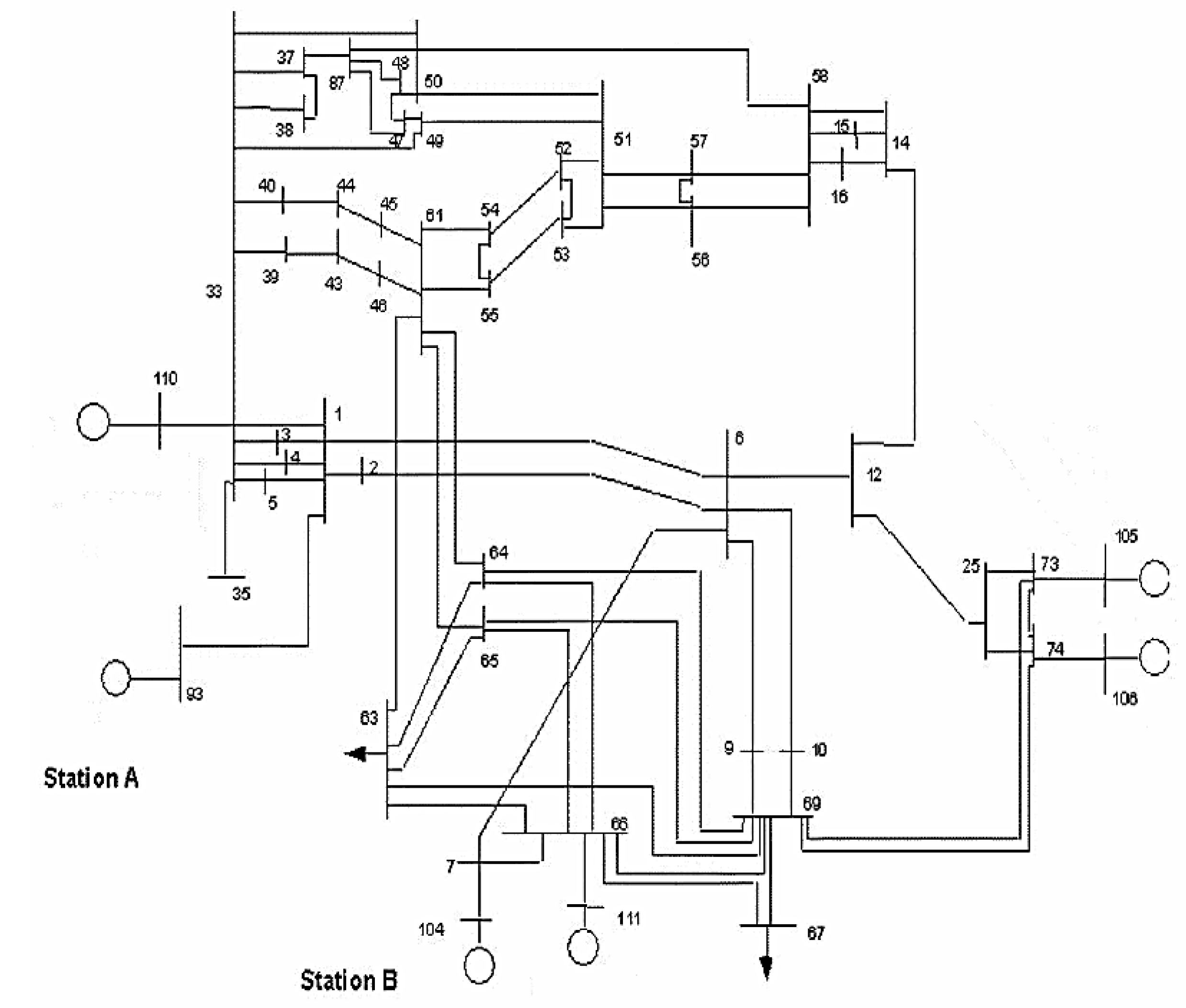
The second system studied in this paper is a 50-machine power system. This power system is known as a medium standard power system. This power system includes all the modeling features and complexity of a large-scale power system that has 50 generators, 145 buses, and 453 lines. The single-line diagram of this system is shown in Figure 18. Information on load and lines is given in reference [68]. In the dynamic studies of this system, there are six generators in buses 93, 110, 104, 111, 105, and 106, which are considered as area 1 and are modeled as a two-axis model equipped with an excitation system. The other 44 generators, as region two, are modeled in a classical model. Loads in this system are modeled with a constant impedance. In this paper, the operating conditions are determined by increasing the active power generation in buses 93 and 110 without changing the loads of the systems. Table 10 summarizes the three operating modes studied in this section for this system. The specific values for the inter-area open-loop mode of the 50-machine system are shown in Table 11. By increasing the generation level in buses 93 and 110, it can be seen that the damping ratio of the inter-area mode 1 with a frequency of 0.65 Hz is almost constant, but the damping ratio of the inter-area mode 2 with a frequency of about 0.42 Hz decreases. Therefore, the mode between region two is considered the critical mode. In this system, the change in the line current value is considered a feedback signal for the attenuator. Therefore, the best installation location for the SSSC is selected by residual analysis [23]. By calculating the residuals at different locations in the studied system, line 66–63 is chosen as the optimal location for the SSSC.
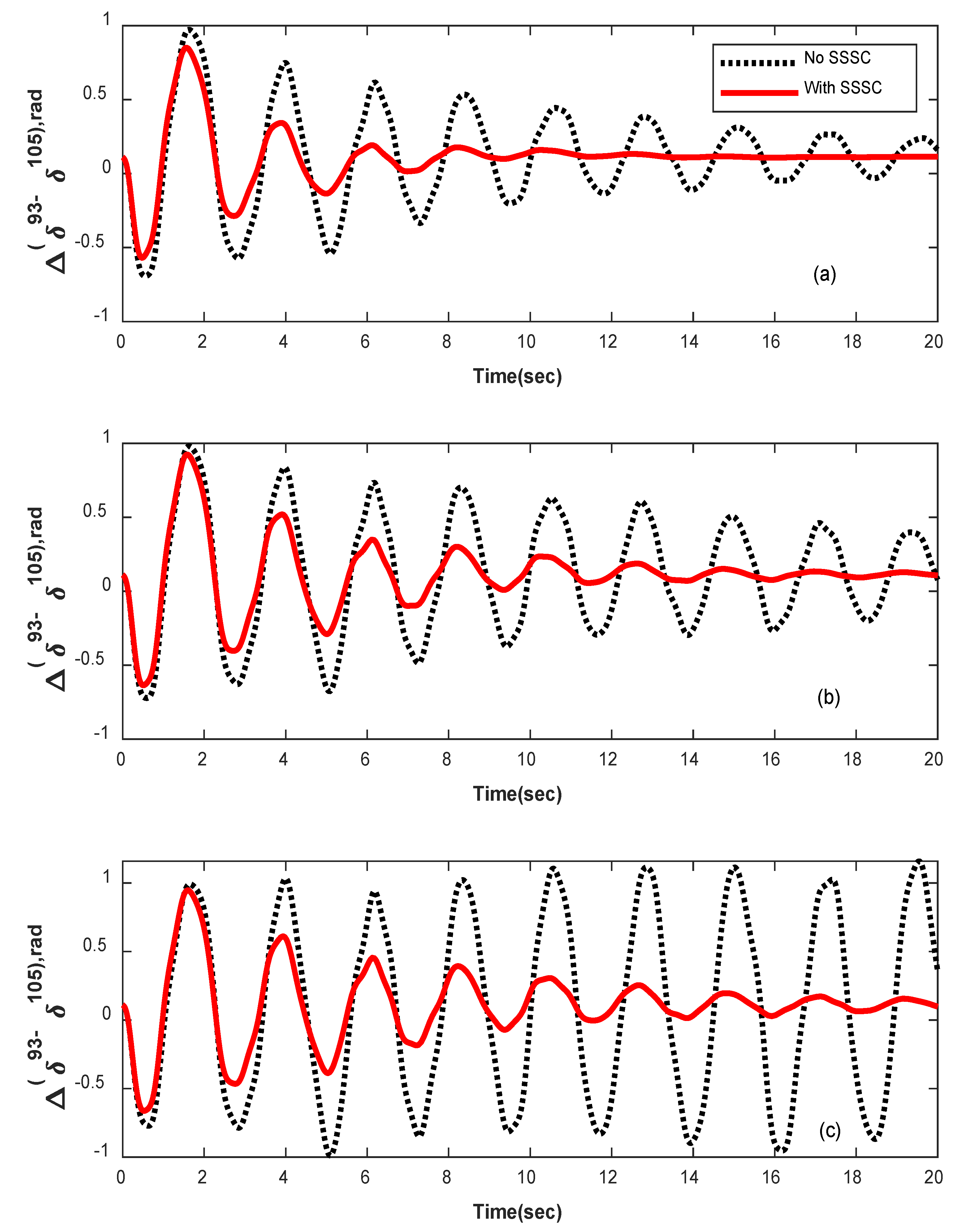
To demonstrate the effectiveness of the SSSC-based stabilizer in the power system of 50 machines, a three-phase fault has been applied to bus 7. The fault is resolved without any line break. Typically, the swing angle changes in G93 relative to G105 under different heavy load conditions for a fault duration of 10 ms (as a small disturbance) for the phase control channel only, are shown in Figure 19. These figures show that the robustly designed SSSC-based stabilizer can effectively cancel the critical inter-area oscillations. Also, the control gain is lower in the phase-based mode, which is in-line with the results of the four-machine system.
According to the results obtained in the four-machine power system, only one scenario is examined in this section. The results of the final scenario are shown in Table 12 and Table 13. The result of the nonlinear simulation of the φ-based SSSC-based stabilizer is also shown in Figure 19.

7. Conclusions

A method for designing an SSSC-based stabilizer to damp inter-area oscillations is proposed in this paper. To reach this goal, a novel objective function was employed. The displacement of critical modes and the gain (control cost) of the stabilizer are taken into account in the given objective function. In order to have an SSSC-based stabilizer with minimum phase structure, appropriate constraints are calculated and appended to the objective function. For the robust design of an SSSC-based stabilizer, different operating conditions are simultaneously considered. A hybrid optimization algorithm (hGWO-GA) is proposed by combining the grey wolf optimizer (GWO) algorithm and the genetic algorithm (GA). The proposed method was tested on two standard test systems of 4 and 50 machines. The eigenvalues analysis and nonlinear simulations prove that the introduced approach can efficiently enhance the damping of inter-area oscillations. The obtained results show the superiority of the SSSC phase-based stabilizer compared to the magnitude-based stabilizer in damping inter-area oscillations. The results also show that the performance of the proposed hGWO-GA optimization algorithm is superior to the GWO, GA, ACO, and PSO algorithms. Considering the uncertainties in the design process is the future scope of this work.

Author Contributions

S.B. and I.F.D.: conceptualization, methodology, software, and writing—original draft; A.Y.A.: investigation, supervision, validation, and writing—review and editing; Z.W.G.: supervision, writing—review and editing, and funding acquisition; J.H.: supervision, writing—review and editing, and funding acquisition. All authors have read and agreed to the published version of the manuscript.

Funding

This research was supported by the Energy Cloud R&D Program through the National Research Foundation of Korea (NRF) funded by the Ministry of Science, ICT (2019M3F2A1073164). This work was also supported by the Gachon University Research Fund of 2019 (GCU-2019-0715).

Data Availability Statement

Not applicable.

Conflicts of Interest

The authors declare no conflict of interest.

Nomenclature

τ d 0 i ,     τ q 0 i Open-circuit d and q axes transient time constants, respectively.
E d   ,   E q   Stator EMFs of the rotor transient flux components on the d and q axes, respectively.
EFDStator EMF of the field voltage.
xeAuxiliary state variable for the excitation system
Xd, XqSynchronous reactance on the d and q axes, respectively.
X d   ,   X q   Transient reactance on the d and q axes, respectively.
Id, IqStator currents on the d and q axes, respectively.
DDamping coefficient.
δRotor angle.
ωRotor angular speed.
ωsThe synchronous speed of the machine.
HInertia constant of the machine.
PmMechanical power applied to the shaft.
PeOutput electrical power of the generator.
X2, X1, X0Parameters of SSSC stabilizer.
TTime constant of SSSC stabilizer.
VinjThe AC voltage provided by the SSSC.
XSCTLeakage reactance of coupling transformer.
σiReal part of ith critical mode.
ζiDamping coefficient of ith critical mode.
ζ0Desired value of damping coefficient of critical modes.
KAExciter gain.
σ0Desired value of the real part of critical modes.
TA, TB, TC, TRTime constants related to the exciter.
m, ϕModulation ratio and phase defined by pulse width modulation. (PWM), respectively.
ρcCrossover percentage.
ϕ refAC voltage injected by the SSSC.
mrefValues of m in steady-state condition.
ILLine current.
ISSLine current in steady-state condition.
ID, IQD and Q components of the line current.
ψPhase of line current IL.
φssPhase of line current IL in steady-state condition.
KPProportional gain of Pl controller.
KIIntegral gain of PI controller.
TwTime constant of washout filter.
IdcDC current of SSSC.
VdcDC voltage of SSSC.
KThe ratio between the AC and DC voltages depending on the converter structure.
CDCDC capacitor value.
NPThe number of operation conditions.
TSSSCTime constants of the SSSC.
NNumber of search agents.
iter-maxMaximum number of iterations.
ρcCrossover percentage.
ρmMutation percentage.

References

  1. Rogers, G. Power System Oscillations; The Kluwer International Series in Engineering and Computer Science: Power Electronics and Power Systems; Kluwer Academic Publishers: Amsterdam, The Netherlands, 2000; ISBN 9780792377122. [Google Scholar]
  2. Kundur, P.; Balu, N.J.; Lauby, M.G. Power System Stability and Control; EPRI power system engineering series; McGraw-Hill: New York, NY, USA, 1994; ISBN 9780070359581. [Google Scholar]
  3. Yu, Y.-N. Electric Power System Dynamics; Academic Press: Cambridge, MA, USA, 1983. [Google Scholar]
  4. Ramos, R.A. Stability Analysis of Power Systems Considering AVR and PSS Output Limiters. Int. J. Electr. Power Energy Syst. 2009, 31, 153–159. [Google Scholar] [CrossRef]
  5. Hingorani, N.G.; Gyugyi, L. Understanding FACTS: Concepts and Technology of Flexible AC Transmission Systems; Wiley: Hoboken, NJ, USA, 2000; ISBN 9780780334557. [Google Scholar]
  6. Zarghami, M.; Crow, M.L.; Sarangapani, J.; Liu, Y.; Atcitty, S. A Novel Approach to Interarea Oscillation Damping by Unified Power Flow Controllers Utilizing Ultracapacitors. IEEE Trans. Power Syst. 2010, 25, 404–412. [Google Scholar] [CrossRef]
  7. Ke, D.P.; Chung, C.Y. An Inter-Area Mode Oriented Pole-Shifting Method with Coordination of Control Efforts for Robust Tuning of Power Oscillation Damping Controllers. IEEE Trans. Power Syst. 2012, 27, 1422–1432. [Google Scholar] [CrossRef]
  8. Mihalič, R.; Papič, I. Static Synchronous Series Compensator—A Mean for Dynamic Power Flow Control in Electric Power Systems. Electr. Power Syst. Res. 1998, 45, 65–72. [Google Scholar] [CrossRef]
  9. Panda, S. Multi-Objective Evolutionary Algorithm for SSSC-Based Controller Design. Electr. Power Syst. Res. 2009, 79, 937–944. [Google Scholar] [CrossRef]
  10. Castro, M.S.; Ayres, H.M.; da Costa, V.F.; da Silva, L.C.P. Impacts of the SSSC Control Modes on Small-Signal and Transient Stability of a Power System. Electr. Power Syst. Res. 2007, 77, 1–9. [Google Scholar] [CrossRef]
  11. Movahedi, A.; Niasar, A.H.; Gharehpetian, G.B. Designing SSSC, TCSC, and STATCOM Controllers Using AVURPSO, GSA, and GA for Transient Stability Improvement of a Multi-Machine Power System with PV and Wind Farms. Int. J. Electr. Power Energy Syst. 2019, 106, 455–466. [Google Scholar] [CrossRef]
  12. Abdelaziz, A.Y.; Ali, E.S. Static VAR Compensator Damping Controller Design Based on Flower Pollination Algorithm for a Multi-Machine Power System. Electr. Power Compon. Syst. 2015, 43, 1268–1277. [Google Scholar] [CrossRef]
  13. Shakarami, M.R.; Kazemi, A. Assessment of Effect of SSSC Stabilizer in Different Control Channels on Damping Inter-Area Oscillations. Energy Convers. Manag. 2011, 52, 1622–1629. [Google Scholar] [CrossRef]
  14. Abd-Elazim, S.M.; Ali, E.S. Imperialist Competitive Algorithm for Optimal STATCOM Design in a Multimachine Power System. Int. J. Electr. Power Energy Syst. 2016, 76, 136–146. [Google Scholar] [CrossRef]
  15. Kazemi, A.; Ladjevardi, M.; Masoum, M.A.S. Optimal Selection of SSSC Based Damping Controller Parameters for Improving Power System Dynamic Stability Using Genetic Algorithm. Iran. J. Sci. Technol. Trans. B Eng. 2005, 29, 1–10. [Google Scholar]
  16. Jowder, F.A.L. Influence of Mode of Operation of the SSSC on the Small Disturbance and Transient Stability of a Radial Power System. IEEE Trans. Power Syst. 2005, 20, 935–942. [Google Scholar] [CrossRef]
  17. Wang, H.F. Static Synchronous Series Compensator to Damp Power System Oscillations. Electr. Power Syst. Res. 2000, 54, 113–119. [Google Scholar] [CrossRef]
  18. Nambu, M.; Ohsawa, Y. Development of an Advanced Power System Stabilizer Using a Strict Linearization Approach. IEEE Trans. Power Syst. 1996, 11, 813–818. [Google Scholar] [CrossRef]
  19. Larsen, E.V.; Swann, D.A. Applying Power System Stabilizers Part II: Performance Objectives and Tuning Concepts. IEEE Trans. Power Appar. Syst. 1981, PAS-100, 3025–3033. [Google Scholar] [CrossRef]
  20. Mokhtari, M.; Aminifar, F.; Nazarpour, D.; Golshannavaz, S. Wide-Area Power Oscillation Damping with a Fuzzy Controller Compensating the Continuous Communication Delays. IEEE Trans. Power Syst. 2013, 28, 1997–2005. [Google Scholar] [CrossRef]
  21. Sharaf, A.M.; Lie, T.T. A Robust Nonlinear Power System Stabilizer. In Proceedings of the 38th Midwest Symposium on Circuits and Systems, Rio de Janeiro, Brazil, 13–16 August 1995; Volume 2, pp. 1098–1101. [Google Scholar]
  22. Safari, A.; Rezaei, N. A Novel Current Injection Model of GCSC for Control and Damping of Power System Oscillations. IETE J. Res. 2013, 59, 768–773. [Google Scholar] [CrossRef]
  23. Panda, S.; Swain, S.C.; Rautray, P.K.; Malik, R.K.; Panda, G. Design and Analysis of SSSC-Based Supplementary Damping Controller. Simul. Model. Pract. Theory 2010, 18, 1199–1213. [Google Scholar] [CrossRef]
  24. Panda, S.; Kiran, S.H.; Dash, S.S.; Subramani, C. A PD-Type Multi Input Single Output SSSC Damping Controller Design Employing Hybrid Improved Differential Evolution-Pattern Search Approach. Appl. Soft Comput. 2015, 32, 532–543. [Google Scholar] [CrossRef]
  25. Hashemi, Y.; Shayeghi, H.; Moradzadeh, M. Design of Dual-Dimensional Controller Based on Multi-Objective Gravitational Search Optimization Algorithm for Amelioration of Impact of Oscillation in Power Generated by Large-Scale Wind Farms. Appl. Soft Comput. 2017, 53, 236–261. [Google Scholar] [CrossRef]
  26. Abd Elazim, S.M.; Ali, E.S. Optimal SSSC Design for Damping Power Systems Oscillations via Gravitational Search Algorithm. Int. J. Electr. Power Energy Syst. 2016, 82, 161–168. [Google Scholar] [CrossRef]
  27. Gholipour, E.; Nosratabadi, S.M. A New Coordination Strategy of SSSC and PSS Controllers in Power System Using SOA Algorithm Based on Pareto Method. Int. J. Electr. Power Energy Syst. 2015, 67, 462–471. [Google Scholar] [CrossRef]
  28. Darabian, M.; Mohseni-Bonab, S.M.; Mohammadi-Ivatloo, B. Improvement of Power System Stability by Optimal SVC Controller Design Using Shuffled Frog-Leaping Algorithm. IETE J. Res. 2015, 61, 160–169. [Google Scholar] [CrossRef]
  29. Socha, K.; Dorigo, M. Ant Colony Optimization for Continuous Domains. Eur. J. Oper. Res. 2008, 185, 1155–1173. [Google Scholar] [CrossRef] [Green Version]
  30. Panda, S.; Yegireddy, N.K.; Mohapatra, S.K. Hybrid BFOA-PSO Approach for Coordinated Design of PSS and SSSC-Based Controller Considering Time Delays. Int. J. Electr. Power Energy Syst. 2013, 49, 221–233. [Google Scholar] [CrossRef]
  31. Jolfaei, M.G.; Sharaf, A.M.; Shariatmadar, S.M.; Poudeh, M.B. A Hybrid PSS–SSSC GA-Stabilization Scheme for Damping Power System Small Signal Oscillations. Int. J. Electr. Power Energy Syst. 2016, 75, 337–344. [Google Scholar] [CrossRef]
  32. Khadanga, R.K.; Satapathy, J.K. Time Delay Approach for PSS and SSSC Based Coordinated Controller Design Using Hybrid PSO–GSA Algorithm. Int. J. Electr. Power Energy Syst. 2015, 71, 262–273. [Google Scholar] [CrossRef]
  33. Panda, S.; Yegireddy, N.K. Multi-Input Single Output SSSC Based Damping Controller Design by a Hybrid Improved Differential Evolution-Pattern Search Approach. ISA Trans. 2015, 58, 173–185. [Google Scholar] [CrossRef]
  34. Sahu, P.R.; Hota, P.K.; Panda, S. Power System Stability Enhancement by Fractional Order Multi Input SSSC Based Controller Employing Whale Optimization Algorithm. J. Electr. Syst. Inf. Technol. 2018, 5, 326–336. [Google Scholar] [CrossRef]
  35. Swain, S.C.; Panda, S.; Mahapatra, S. A Multi-Criteria Optimization Technique for SSSC Based Power Oscillation Damping Controller Design. Ain Shams Eng. J. 2016, 7, 553–565. [Google Scholar] [CrossRef] [Green Version]
  36. Wolpert, D.H.; Macready, W.G. No Free Lunch Theorems for Optimization. IEEE Trans. Evol. Comput. 1997, 1, 67–82. [Google Scholar] [CrossRef]
  37. Khan, N.; Ullah, F.U.M.; Haq, I.U.; Khan, S.U.; Lee, M.Y.; Baik, S.W. AB-Net: A Novel Deep Learning Assisted Framework for Renewable Energy Generation Forecasting. Mathematics 2021, 9, 2456. [Google Scholar] [CrossRef]
  38. Satheesh, R.; Chakkungal, N.; Rajan, S.; Madhavan, M.; Alhelou, H.H. Identification of Oscillatory Modes in Power System Using Deep Learning Approach. IEEE Access 2022, 10, 16556–16565. [Google Scholar] [CrossRef]
  39. Huang, R.; Gao, W.; Fan, R.; Huang, Q. A Guided Evolutionary Strategy Based Static Var Compensator Control Approach for Inter-Area Oscillation Damping. IEEE Trans. Ind. Inform. 2022. [Google Scholar] [CrossRef]
  40. Huang, R.; Gao, W.; Fan, R.; Huang, Q. Damping Inter-area Oscillation Using Reinforcement Learning Controlled TCSC. IET Gener. Transm. Distrib. 2022, 16, 2265–2275. [Google Scholar] [CrossRef]
  41. Jamsheed, F.; Iqbal, S.J. An Adaptive Neural Network-Based Controller to Stabilize Power Oscillations in Wind-Integrated Power Systems. IFAC-PapersOnLine 2022, 55, 740–745. [Google Scholar] [CrossRef]
  42. Abumeteir, H.A.; Vural, A.M. Design and Optimization of Fractional Order PID Controller to Enhance Energy Storage System Contribution for Damping Low-Frequency Oscillation in Power Systems Integrated with High Penetration of Renewable Sources. Sustainability 2022, 14, 5095. [Google Scholar] [CrossRef]
  43. Welhazi, Y.; Guesmi, T.; Alshammari, B.M.; Alqunun, K.; Alateeq, A.; Almalaq, Y.; Alsabhan, R.; Abdallah, H.H. A Novel Hybrid Chaotic Jaya and Sequential Quadratic Programming Method for Robust Design of Power System Stabilizers and Static VAR Compensator. Energies 2022, 15, 860. [Google Scholar] [CrossRef]
  44. Mirjalili, S.; Mirjalili, S.M.; Lewis, A. Grey Wolf Optimizer. Adv. Eng. Softw. 2014, 69, 46–61. [Google Scholar] [CrossRef] [Green Version]
  45. Precup, R.-E.; David, R.-C.; Petriu, E.M. Grey Wolf Optimizer Algorithm-Based Tuning of Fuzzy Control Systems with Reduced Parametric Sensitivity. IEEE Trans. Ind. Electron. 2017, 64, 527–534. [Google Scholar] [CrossRef]
  46. Song, X.; Tang, L.; Zhao, S.; Zhang, X.; Li, L.; Huang, J.; Cai, W. Grey Wolf Optimizer for Parameter Estimation in Surface Waves. Soil Dyn. Earthq. Eng. 2015, 75, 147–157. [Google Scholar] [CrossRef]
  47. Emary, E.; Zawbaa, H.M.; Grosan, C.; Hassenian, A.E. Feature Subset Selection Approach by Gray-Wolf Optimization. In Afro-European Conference for Industrial Advancement; Springer: Cham, Switzerland, 2015; pp. 1–13. [Google Scholar]
  48. Mirjalili, S. How Effective Is the Grey Wolf Optimizer in Training Multi-Layer Perceptrons. Appl. Intell. 2015, 43, 150–161. [Google Scholar] [CrossRef]
  49. Pradhan, M.; Roy, P.K.; Pal, T. Grey Wolf Optimization Applied to Economic Load Dispatch Problems. Int. J. Electr. Power Energy Syst. 2016, 83, 325–334. [Google Scholar] [CrossRef]
  50. Shakarami, M.R.; Davoudkhani, I.F. Wide-Area Power System Stabilizer Design Based on Grey Wolf Optimization Algorithm Considering the Time Delay. Electr. Power Syst. Res. 2016, 133, 149–159. [Google Scholar] [CrossRef]
  51. Jayakumar, N.; Subramanian, S.; Ganesan, S.; Elanchezhian, E.B. Grey Wolf Optimization for Combined Heat and Power Dispatch with Cogeneration Systems. Int. J. Electr. Power Energy Syst. 2016, 74, 252–264. [Google Scholar] [CrossRef]
  52. Sulaiman, M.H.; Mustaffa, Z.; Mohamed, M.R.; Aliman, O. Using the Gray Wolf Optimizer for Solving Optimal Reactive Power Dispatch Problem. Appl. Soft Comput. 2015, 32, 286–292. [Google Scholar] [CrossRef] [Green Version]
  53. Niu, P.; Niu, S.; Liu, N.; Chang, L. The Defect of the Grey Wolf Optimization Algorithm and Its Verification Method. Knowl.-Based Syst. 2019, 171, 37–43. [Google Scholar] [CrossRef]
  54. Hu, P.; Pan, J.-S.; Chu, S.-C. Improved Binary Grey Wolf Optimizer and Its Application for Feature Selection. Knowl.-Based Syst. 2020, 195, 105746. [Google Scholar] [CrossRef]
  55. Sultana, U.; Khairuddin, A.B.; Mokhtar, A.S.; Zareen, N.; Sultana, B. Grey Wolf Optimizer Based Placement and Sizing of Multiple Distributed Generation in the Distribution System. Energy 2016, 111, 525–536. [Google Scholar] [CrossRef]
  56. Fathy, A.; Abdelaziz, A.Y. Grey Wolf Optimizer for Optimal Sizing and Siting of Energy Storage System in Electric Distribution Network. Electr. Power Compon. Syst. 2017, 45, 601–614. [Google Scholar] [CrossRef]
  57. Yang, B.; Zhang, X.; Yu, T.; Shu, H.; Fang, Z. Grouped Grey Wolf Optimizer for Maximum Power Point Tracking of Doubly-Fed Induction Generator Based Wind Turbine. Energy Convers. Manag. 2017, 133, 427–443. [Google Scholar] [CrossRef]
  58. Sauer, P.W.; Pai, A. Power System Dynamics and Stability; Stipes Publishing LLC: Champaign, IL, USA, 2006; ISBN 9781588746733. [Google Scholar]
  59. Anderson, P.M.; Fouad, A.A. Power System Control and Stability; Wiley India Pvt. Limited: Delhi, India, 2008; ISBN 9788126518180. [Google Scholar]
  60. Muro, C.; Escobedo, R.; Spector, L.; Coppinger, R.P. Wolf-Pack (Canis lupus) Hunting Strategies Emerge from Simple Rules in Computational Simulations. Behav. Process. 2011, 88, 192–197. [Google Scholar] [CrossRef] [PubMed]
  61. Madadi, A.; Motlagh, M.M. Optimal Control of DC Motor Using Grey Wolf Optimizer Algorithm. Tech. J. Eng. Appl. Sci. 2014, 4, 373–379. [Google Scholar]
  62. Tawhid, M.A.; Ali, A.F. A Hybrid Grey Wolf Optimizer and Genetic Algorithm for Minimizing Potential Energy Function. Memetic Comput. 2017, 9, 347–359. [Google Scholar] [CrossRef]
  63. Kamboj, V.K. A Novel Hybrid PSO–GWO Approach for Unit Commitment Problem. Neural Comput. Appl. 2016, 27, 1643–1655. [Google Scholar] [CrossRef]
  64. Gai, W.; Qu, C.; Liu, J.; Zhang, J. A Novel Hybrid Meta-Heuristic Algorithm for Optimization Problems. Syst. Sci. Control Eng. 2018, 6, 64–73. [Google Scholar] [CrossRef] [Green Version]
  65. Dorf, R.C.; Bishop, R.H. Modern Control Systems; Pearson Education; Prentice Hall: Hoboken, NJ, USA, 2001; ISBN 9780130306609. [Google Scholar]
  66. Abdel-magid, Y.L.; Abido, M.A. Optimal Multiobjective Design of Robust Power System Stabilizers Using Genetic Algorithms. Power Syst. IEEE Trans. 2003, 18, 1125–1132. [Google Scholar] [CrossRef] [Green Version]
  67. Ali, E.S. Optimization of Power System Stabilizers Using BAT Search Algorithm. Int. J. Electr. Power Energy Syst. 2014, 61, 683–690. [Google Scholar] [CrossRef]
  68. Transient Stability Test Systems for Direct Stability Methods. IEEE Trans. Power Syst. 1992, 7, 37–43. [CrossRef]
Figure 1. Block diagram of the exciter.
Energies 15 08754 g001
Figure 2. Block diagram of the SSSC stabilizer.
Energies 15 08754 g002
Figure 3. Block diagram of the SSSC stabilizer with new state variables.
Energies 15 08754 g003
Figure 4. Structure of the SSSC installed between buses i and j.
Energies 15 08754 g004
Figure 5. SSSC phase controller with a damping stabilizer.
Energies 15 08754 g005
Figure 6. SSSC magnitude controller with a damping stabilizer.
Energies 15 08754 g006
Figure 7. Grey wolf social structure (dominance decreases from to own).
Energies 15 08754 g007
Figure 8. Pseudocode of the hGWO-GA algorithm.
Energies 15 08754 g008
Figure 9. Range of displacement of the eigenvalues.
Energies 15 08754 g009
Figure 11. Fitness convergence for robust solution (φ-based stabilizer).
Energies 15 08754 g011
Figure 12. Fitness convergence for robust solution (m-based stabilizer).
Energies 15 08754 g012
Figure 13. Nonlinear simulations in light loading using a robust-based stabilizer designed by the hGWO-GA algorithm ((a) angle difference between G1 and G3, (b) magnitude of voltage bus 5, and (c) transmitted power between area1 and area2, (d) rotor speed of generator G1).
Energies 15 08754 g013
Figure 14. Nonlinear simulations in normal loading using a robust-based stabilizer designed by the hGWO-GA algorithm ((a) angle difference between G1 and G3, (b) magnitude of voltage bus 5, and (c) transmitted power between area1 and area2, (d) rotor speed of generator G1).
Energies 15 08754 g014
Figure 15. Nonlinear simulations in heavy loading using a robust-based stabilizer designed by the hGWO-GA algorithm ((a) angle difference between G1 and G3, (b) magnitude of voltage bus 5, and (c) transmitted power between area1 and area2, (d) rotor speed of generator G1).
Energies 15 08754 g015
Figure 16. Nonlinear simulations in heavy loading using a robust φ-based stabilizer for different optimization algorithms ((a) angle difference between G1 and G3, (b) magnitude of voltage bus 5, and (c) transmitted power between area1 and area2, (d) rotor speed of generator G1).
Energies 15 08754 g016
Figure 17. Nonlinear simulations in heavy loading using a robust m-based stabilizer for different optimization algorithms ((a) angle difference between G1 and G3, (b) magnitude of voltage bus 5, (c) transmitted power between area1 and area2, (d) rotor speed of generator G1).
Energies 15 08754 g017
Figure 18. Two-area fifty-machine power system [68].
Energies 15 08754 g018
Figure 19. Nonlinear simulations using robust φ -based stabilizer for different operating conditions (angle difference between G93 and G105) ((a) light loading, (b) Normal loading, and (c) Heavy loading).
Energies 15 08754 g019
Table 1. Parameter settings of algorithms.
ParametersValues
Search agents100
Number of populations40
a(2, 0)
ρc0.5
ρm01
Table 2. The summary of operating conditions of IEEE 4-Machine Power System.
Operation ConditionsTransmitted Power (MW)Load of Area 1
(MW)
Load of Area 2
(MW)
1Light loading3509501350
2Normal loading3809201380
3Heavy loading4208901410
Table 3. Open-loop oscillation modes of IEEE 4-Machine Power System.
Light LoadingNormal LoadingHeavy Loading
EigenvaluesFrequencyDampingEigenvaluesFrequencyDampingEigenvaluesFrequencyDamping
−1.44090 ± j7.7022 *1.2258018.3887−1.239600 ± j7.738301.2316015.8180−1.252700±
j7.71210
1.2274016.0334
−1.83680 ± j7.43861.1839023.9729−1.566800 ± j7.510601.1953020.4215−1.573100 ± j7.500801.1938020.5257
−0.53479 ± j2.53440.4033620.6468−0.397540 ± j2.606300.4148015.0788−0.474010 ±
j2.82720
0.4499616.5354
−0.14050 ± j1.99770.317947.01610−0.063853 ± j1.965300.312793.24730−0.0097979 ± j1.67210.266120.58595
−1.16880 ± j0.69160.1100786.0629−1.235800 ± j0.871860.1387681.7120−1.366100 ± j0.795890.1266786.4058
−0.55308 ± j0.85770.1365254.1907−0.579360 ± j0.829350.1319957.2679−0.584710 ± j0.828830.1319157.6458
* The letter “j” represents the imaginary part of eigenvalues.
Table 4. Parameters of optimal SSSC-based stabilizers.
Operation
Conditions
MethodControl
Chanel
x2x1x0|f()|ω = 2Best
Solution
Worst
Solution
MeanStandard
Deviation
LightGAφ-based0.106780.519290.631330.636639.294110.00729.60620.26655
m-based0.101810.279970.0636320.3951414.030614.332814.14260.13222
ACOφ-based1 × 10−91 × 10−90.0482840.0290418.25918.26028.25940.00010515
m-based0.097050.267020.0614070.3765714.360714.56514.43920.075383
PSOφ-based0.00102990.0144710.0508220.00699458.25868.25978.25821.5783 × 10−7
m-based0.03358700.3050800.5527800.217560013.947114.407714.22350.25188
GWOφ-based0.00102770.0144690.0508110.00698138.25838.25938.25768.2996 × 10−12
m-based0.01598000.2305300.4764600.108700013.946913.996213.97210.023352
hGWO-GAφ-based1.2519 × 10−92.4479 × 10−90.0482840.00290418.25738.25738.25737.0711 × 10−14
m-based0.138120.474210.322270.15870213.947813.994813.96660.017794
NormalGAφ-based8.7305 × 10−50.0046820.0692980.04185112.316112.442612.36960.059309
m-based0.147950.451910.188480.5952912.158812.518312.27790.13958
ACOφ-based7.0503 × 10−50.00462590.06930.04188312.315513.856613.270.63718
m-based0.149010.430320.14490.5844512.073812.859412.29390.32619
PSOφ-based7.686 × 10−50.00461260.0693450.0418912.315512.452612.34330.061121
m-based0.169380.457530.104420.649412.015212.729212.32780.35177
GWOφ-based7.6587 × 10−50.00460890.069340.0418812.315412.315612.31540.0001004
m-based0.169690.456330.10380.6487812.014812.061912.02760.020104
hGWO-GAφ-based7.6223 × 10−50.00461710.0693050.04187112.315312.315312.31534.5423 × 10−9
m-based0.169720.456150.103450.6487412.014612.019512.01610.0018901
HeavyGAφ-based0.0585820.372090.590340.496184.81385.71085.31330.35412
m-based0.244320.652980.219260.908215.49116.12375.66480.27551
ACOφ-based1 × 10−90.00724730.217130.130893.694133.95783.760070.11238
m-based0.228120.573450.129270.835325.49175.80315.69070.1291
PSOφ-based5.7478 × 10−50.00726370.217440.130933.693920.694583.694182.8844 × 10−4
m-based0.227570.572070.128830.833355.52065.76045.61250.092362
GWOφ-based6.07 × 10−50.00726650.217450.130933.693670.69393.693749.7524 × 10−5
m-based0.226520.573750.130650.832995.49125.49145.49138.007 × 10−4
hGWO-GAφ-based3.9445 × 10−50.00727640.217330.130913.693633.693633.693631.2648 × 10−7
m-based0.226960.570750.128520.831315.49115.49125.49122.635 × 10−5
Table 5. Inter-area mode for the closed-loop system in optimal design.
MethodOperation
Conditions
Control
Chanel
Inter-Area ModeFrequencyDamping
GALightφ-based−0.40095 ± j2.23510.3557317.6568
m-based−0.4141± j2.17180.3456618.7294
Normalφ-based−0.35255 ± j2.48680.3957814.0367
m-based−0.38728 ± j2.42020.3851815.8012
Heavyφ-based−0.37266 ± j2.50120.3980714.7368
m-based−0.38776 ± j2.36550.3764816.1767
ACOLightφ-based−0.47264 ± j2.44870.3897218.9521
m-based−0.43594 ± j2.23530.3557519.1424
Normalφ-based−0.34681 ± j2.417800.3848014.1989
m-based−0.40364 ± j2.344700.3731816.9652
Heavyφ-based−0.40935 ± j2.585000.4114215.6404
m-based−0.47658 ± j2.695800.4290517.4084
PSOLightφ-based−0.44330 ± j2.238100.3562019.4296
m-based−0.49388 ± j2.45960.3914719.6864
Normalφ-based−0.41281 ± j2.29320.3649717.7167
m-based−0.42412 ± j2.32850.370617.9191
Heavyφ-based−0.42699 ± j2.22930.354818.8121
m-based−0.42268 ± j2.19320.3490618.9235
GWOLightφ-based−0.44322 ± j2.237300.3560819.4329
m-based−0.47893 ± j2.36570.3765119.8427
Normalφ-based−0.46955 ± j2.361400.3758219.5030
m-based−0.65311 ± j3.199600.5092319.9998
Heavyφ-based−0.33959 ± j1.646100.2619820.2045
m-based−0.38720 ± j2.008900.3197318.9255
hGWO-GALightφ-based−0.4789 ± j2.38650.3798319.6779
m-based−0.46014 ± j2.23480.3556820.1666
Normalφ-based−0.47809 ± j2.31720.3687920.2068
m-based−0.48337 ± j2.25710.3592420.9403
Heavyφ-based−0.48098 ± j2.19420.3492221.412
m-based−0.48582 ± j2.18950.3484721.6617
Table 6. Parameters of robust SSSC-based stabilizer of IEEE 4-Machine Power System.
MethodControl
Chanel
x2x1x0|f()|ω = 2Best
Solution
Worst
Solution
MeanStandard Deviation
GAφ-based0.000905970.0164770.0749150.04723826.260630.169629.13971.6399
m-based0.0989790.314280.13830.4085833.009533.328733.1550.11562
ACOφ-based0.000709310.014064 0.0703640.04399726.259726.372626.29560.046606
m-based0.187890.779920.775880.9382932.866933.817933.31540.37004
PSOφ-based0.000526010.0121750.0704330.04362826.258126.269626.26270.0062581
m-based0.129520.423550.249380.5345232.552634.022133.13590.55727
GWOφ-based0.000482810.0116470.070240.04340826.258126.258126.25814.0769 × 10−5
m-based0.116630.347220.139410.4616932.543532.623632.58240.038191
hGWO-GAφ-based0.000487770.0117050.0702230.0434126.258126.258126.25817.2406 × 10−7
m-based0.118690.359460.157180.4727232.543132.551332.54780.0036343
Table 7. Inter-area mode for the closed-loop system in the robust design.
MethodOperation
Conditions
Control
Chanel
Inter-Area ModeFrequencyDamping
GALightφ-based−0.32482 ± j2.14070.340715.002
m-based−0.36786 ± j2.29360.3650315.8365
Normalφ-based−0.36541 ± j2.3380.3721115.4415
m-based−0.39475 ± j2.50460.3986215.5686
Heavyφ-based−0.37819 ± j2.39510.381215.5964
m-based−0.37665 ± j2.38060.3788815.6277
ACOLightφ-based−0.32699 ± j2.04180.3249615.8132
m-based−0.39191 ± j2.39250.3807816.1652
Normalφ-based−0.33822 ± j2.05620.3272516.2309
m-based−0.41517 ± j2.46280.3919716.6228
Heavyφ-based−0.37631 ± j2.26650.3607316.379
m-based−0.37078 ± j2.21780.3529816.4891
PSOLightφ-based−0.39107 ± j2.330700.3709516.5475
m-based−0.61917 ± j3.033300.4827620.0000
Normalφ-based−0.33557 ± j2.01060.3199916.4624
m-based−0.43774 ± j2.010400.3199621.2759
Heavyφ-based−0.45483 ± j2.775900.4418016.1690
m-based−0.37818 ± j2.22410.3539816.7629
GWOLightφ-based−0.40631 ± j2.345100.3732417.0716
m-based−0.75845 ± j3.728800.5934619.9322
Normalφ-based−0.4875 ± j2.45650.3909619.4657
m-based−0.50764 ± j2.45560.3908220.2445
Heavyφ-based−0.46119 ± j2.566600.4084917.6855
m-based−0.30479 ± j1.599200.2545218.7221
hGWO-GALightφ-based−0.45845 ± j2.42970.3866918.5416
m-based−0.46532 ± j2.26720.3608320.1052
Normalφ-based −0.5417 ± j2.49430.3969821.2239
m-based−0.55812 ± j2.41430.3842422.5237
Heavyφ-based−0.47674 ± j2.40940.3834719.4106
m-based−0.52269 ± j2.43450.3874620.992
Table 8. Parameters of robust SSSC-based stabilizer (F2 and F3).
MethodControl
Chanel
x2x1x0|f()|ω = 2Best
Solution
Worst
Solution
MeanStandard Deviation
GAφ-based0.303191.42381.65951.733729.652130.314729.87140.27371
m-based0.356441.80172.0432.198827.246827.711627.54510.18857
ACOφ-based0.297591.38921.61261.690328.856929.469129.28730.26223
m-based0.248621.13691.28881.37927.211227.752627.39990.21181
PSOφ-based0.326311.55041.83661.892227.651629.427428.35010.98264
m-based0.315811.48941.75011.815427.157227.529127.34810.17127
GWOφ-based0.345171.66692.0102.040627.631829.426629.06720.080238
m-based0.356541.78862.04232.183227.128727.300727.20540.072766
hGWO-GAφ-based0.358751.83132.27652.260327.631627.631827.63169.8419 × 10−5
m-based0.359831.85412.37542.300325.997327.280026.83425.718 × 10−5
Table 9. Inter-area mode for the closed-loop system in robust design (F2 and F3).
MethodOperation
Conditions
Control
Chanel
Inter-Area ModeFrequencyDamping
GALightφ-based−0.42097 ± j2.33550.371717.7392
m-based−0.43493 ± j2.38160.3790417.9651
Normalφ-based−0.42025 ± j2.24930.3579918.3658
m-based−0.41516 ± j2.15430.3428618.9233
Heavyφ-based−0.41839 ± j2.18370.3475418.8178
m-based−0.39387 ± j2.04130.3248918.9454
ACOLightφ-based−0.39081 ± j2.05530.3271118.6801
m-based−0.39711 ± j2.06210.3281918.9105
Normalφ-based−0.39287 ± j2.10520.3350518.3456
m-based−0.40598 ± j2.11340.3363618.8647
Heavyφ-based−0.40859 ± j2.14210.3409318.7363
m-based−0.44466 ± j2.30570.3669718.9361
PSOLightφ-based−0.44853 ± j2.43220.387118.1351
m-based−0.45626 ± j2.27150.3615119.6934
Normalφ-based−0.45614 ± j2.30560.3669519.4077
m-based−0.50681 ± j2.50270.3983219.8475
Heavyφ-based−0.4924 ± j2.48120.394919.4654
m-based−0.43896 ± j2.17050.3454519.8225
GWOLightφ-based−0.41587 ± j2.03840.3244319.9894
m-based−0.41577 ± j2.01130.3201120.2433
Normalφ-based−0.42641 ± j2.05710.327420.2971
m-based−0.53132 ± j2.40190.3822721.5988
Heavyφ-based−0.51189 ± j2.46140.3917520.3607
m-based−0.52069 ± j2.39730.3815421.2248
hGWO-GALightφ-based−0.53998 ± j2.30440.3667522.8148
m-based−0.58932 ± j2.4440.3889723.4414
Normalφ-based−0.59398 ± j2.35160.3742724.4892
m-based−0.59716 ± j2.28810.3641625.2527
Heavyφ-based−0.59082 ± j2.36480.3763724.2391
m-based−0.59845 ± j2.26080.3598225.5889
Table 10. The summary of operating conditions of IEEE 50-Machine Power System.
Operating ConditionsPower Generator 1 (MW)Power Generator 5 (MW)
1Light10001000
2Normal13001300
3Heavy15001500
Table 11. Open-loop inter-area modes of IEEE 50-Machine Power System.
Operating ConditionsEigenvaluef (Hz)% ζ
Light−0.2035471 ± j 4.1103350.65418014.946020
−0.043846 ± j 2.8171760.44836761.556208
Normal−0.2007885 ± j4.0994220.65244334.892106
−0.025205 ± j2.72640630.43392100.924452
Heavy−0.1962766 ± j 4.0781230.64905354.8073510
−0.0088798 ± j 2.6495490.42168890.3351424
Table 12. Parameters of robust SSSC-based stabilizer of IEEE 50-Machine Power System.
Method Control
Chanel
x2x1x0|f()|ω = 2
hGWO-GAφ-based0.34030.12270.47840.0437
m-based0.30390.82450.13360.1174
Table 13. Close-loop inter-area modes φ-based with hGWO-GA.
Operating ConditionsEigenvaluef (Hz)% ζ
Light−1.074756 ± j3.955990.629615326.21749
−0.2919746 ± j2.8717080.457046510.11513
Normal−0.626452 ± 4.074340.648451315.19696
−0.1784636 ± j2.8527720.45403276.24359
Heavy−0.3705224 ± j4.1077040.65376148.983708
−0.1075782 ± j2.8458780.45293563.777444
Publisher’s Note: MDPI stays neutral with regard to jurisdictional claims in published maps and institutional affiliations.