Abstract
Due to high electricity prices and possible shortages of gas and other energy commodities, various fluctuations in electricity generation will need to be regulated. Given the increasing expansion of wind power plants in Europe and worldwide. It is necessary and essential to put power regulation into practice, as mandated by regulation 2016/631 EU. A significant power balance problem may arise on the grid, which may lead to cyclical and recurring blackouts in the future. The motivation for this paper is to raise awareness of the controllability of wind turbines and to highlight the gentle pace of research in this area for pitch angle control. Therefore, the chief idea of the paper is to develop a proposal for wind power plant power control by changing the rotor blade rotation, following previous research in this area, and determining the shortcomings and possibilities. The paper provides a numerical method for controlling the power output of a wind power plant, for which an algorithm has been proposed. This control is intended to provide a framework for the design and implementation of a wind power plant control program. Coordination between the multiple sources will fulfil a leading role in smooth power management.
1. Introduction
The operating principle of a wind turbine is simple. The wind acts on the blades of a wind turbine, generating lift and exerting a turning force. The rotating blades transfer the mechanical energy of rotation to a shaft inside the nacelle, which is connected to the gearbox. The gearbox modifies the rotational speed to a suitable level for the generator, which uses rotating magnetic fields to convert the mechanical energy into electrical energy. Wind energy technology has evolved rapidly over the last three decades, with increasing rotor diameter and the use of sophisticated power electronics to allow operation at variable rotor speeds. The design of the wind farm also has an influence on the airflow and the interactions between turbines. Considering the space constraints due to the already enormous size of the wind turbine itself, the design must also consider the interactions between the individual wind turbines. That is to say, the mutual influence between the individual turbines will certainly not be zero [1].
Wind turbine speed control is an important part of any wind farm today. Speed control is possible thanks to the built-in blade rotation system. Turbine power can be regulated by speed control. The blade rotation system is a necessity for the highest possible efficiency of electricity production [2]. Regardless of the type of system, it can be said that it is a decisive factor in the return on investment and profit generation.
Due to the increasing requirements of the system, it will be necessary in the future for the blade rotation system to be used to regulate the power of the wind power plant according to the fords of the network (depending on the grid frequency). The assumption of how to ensure power control by changing the angle of attack is described in this article, which focuses on “Design of Wind of Power Control”. There are several types of blade rotation systems, and this article looks at a newer type of pitch system.
The twist angle distribution of a wind turbine blade determines its efficiency in terms of electricity production. Because the blade is typically used in dynamic wind environments with wide variations in wind speed, it is critical to search for the optimal twist angle distribution for different wind speeds and the required power for grid [3].
In the article [4] by Pranav Patel et al., they evaluate wind forecasting using forecasting systems such as the Persistence Algorithm, ARMA, and their variations, such as Least Penalty. For the use of the pitch system to control the power output, it will therefore be crucial to find out what the wind forecast will be so that the wind farm can be set up as optimally as possible according to the proposed algorithm per the needs of the grid. With appropriate forecasting, battery usage can be minimized, thereby extending battery life; however, at the cost of life extension, the wind farm operator will pay penalties to the grid operator for not delivering the agreed amount of energy. It is for this reason, too, that we need to consider what alternative ways of storing energy are available that would be flexible enough not only for wind farms but also for other renewable energy sources. The current research on battery systems has progressed, but not to the level where it can be used in power engineering.
In the article [5] by Harsh S. Dhiman et al., they evaluate a major part of condition monitoring (CM), identifying patterns in wind turbine variables like route or speed, power output, gearbox temperature, gear bearing temperature, and generator faults. A commonly used CM system in modern-day wind turbines consists of sensor-based networks from which the failure is identifiable. Wind turbines observe highly irregular loads due to stochastic and turbulent wind conditions, which makes components undergo high stress throughout their lifetime. If we consider the objective of this article, namely the control of power according to the angle of attack, the system will certainly be more stressed than it would be according to the approach of paper [4]. This raises the stakes for condition monitoring of all components.
In the article [6] by Shaimaa K. El-Baklish et al., they evaluate the nonlinear model predictive controller (NMPC) for pitch control of horizontal-axis wind turbines. This was compared to another NMPC pitch controller, which used a lumped-mass drive-train model as a freeloader, and to the baseline gain-scheduled PI pitch controller. The developed NMPC pitch controller stabilized the rotor speed and generated power to the rated values at high wind speeds with the turbine rotor over-speeding. However, an NMPC pitch controller, which uses the simplified drive-train prediction model, and the baseline gain-scheduled PI pitch controller, failed to do so due to the significant increase of the coupled deflections, which implies the occurrence of instability. For this reason, in this article we will focus on strong winds.
In the article [7] by Aksher Bhowon et al., they provide a literature review for a research issue focused on wind turbines for grid frequency support applications. A literature review was conducted on 56 articles published between 2015 and 2022, yielding remarkable results. For the control method, the following distribution emerged from the literature, as explained in Figure 1, where “overspeed control” achieved the same number of articles as “pitch angle”, namely five publications from this period. This was followed by “hidden inertial control” and “fast power reserve”, which reached seven publications. An alternative solution for the application of wind power to support frequency was the use of an “energy storage system”, which would act as a controller to produce maximum use of the wind energy, with this solution gaining up to nine publications. The certain winner for the frequency control application was the “droop control” method, which clearly had the most publications from this period with a total of 23. A secondary aim of this paper is, therefore, to encourage research into this remaining method of pitch angle control. The proposed algorithm can be applied to the whole wind farm, thus minimizing the power loss on the turbines due to the higher blade pitch and thus controlling the power itself.
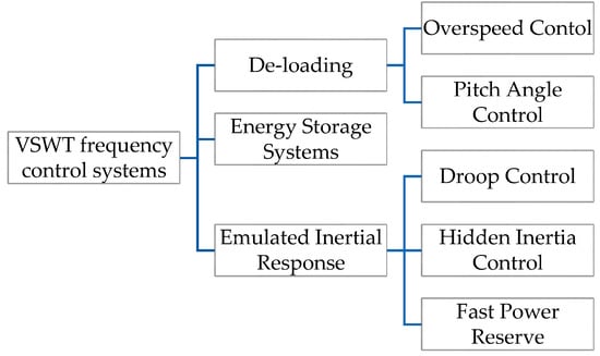
Figure 1.
Classification of variable-speed wind turbines frequency control system [7].
One of the serious drawbacks of wind farms is their impact on the surrounding environment and local communities in terms of generating certain noise intensities that can cause discomfort to the population and have an impact on birds. The World Health Organization has suggested that noise limits should be set at 55 dB during the day and 40 dB at night, but different countries implement different limits. Wind turbine noise levels usually fall below the WHO limits within 400 m of the turbine. However, it is known that wind and temperature gradients can affect its propagation [8].
Studies have not yet confirmed a direct (primary) impact of noise on human health. According to the research that was carried out in the north of Portugal at the Fafe Highlands wind farm (Terras Altas de Fafe), according to a publication [9], it has rather an indirect (secondary) effect, and thus the discomfort and moodiness of the individual can have a negative effect on sleep and psychological problems. Furthermore, the study found that people tolerated the value of noise worse if they were convinced of the unjustifiability of wind energy use than those who agreed with it. In particular, the willingness of individuals to make additional modifications to their homes to improve sound insulation is considered to reflect their beliefs about the causal link between noise and health effects, as well as the intensity of their suffering caused by noise.
Next, the reason for the introduction of the European Union Commission Regulation 2016/631 is briefly explained. This section also describes some of the introductory articles of the regulation, such as the scope and application of this regulation to the various electricity generations according to their importance [10]. The core of the article contains the power regulation of the wind power plant, which deals with the design of power regulation in practice depending on the wind speed, wind direction, the current angle of rotation of the rotor blades, and the frequency of the network [11].
The novel aspect of this article is the design and testing of a new algorithm for a wind turbine controller on three model scenarios, which incorporates European Union regulation 2016/631, since some controllers do not always have this regulation implemented. Therefore, it is necessary to point out such a fact as the remedy for already applied wind farms that have such a controller and wind farms under construction. This regulation is to ensure the possibility to regulate in case of a drop or increase in frequency and thus to maintain the stability of the system and not to use the maximum power of the farm for a quick return on investment. The newly developed algorithm considers the maximum possible generation under the current weather conditions. Reducing production by a certain percentage for the possibility of frequency control is uncommon.
The design of power regulation is demonstrated on a computer program created in the MATLAB application. In the following section, three different conditions in which the wind farm was located were evaluated using the program. From these results, graphical dependencies were subsequently constructed, which are used to explain the operation of power control. Finally, the work deals with the evaluation of the obtained results and their use in practice.
The following figure (Figure 2) shows the two basic angles (positions) of rotation of the blades. Figure 2A shows the normal position during operation. When the wind is fully utilized, the turbine produces the most power. The angle of the turbine blade corresponds to the value α = 0°. The second position can be seen in Figure 2B. In this case, the turbine blades are rotated at an angle α = 90°. It is a neutral position [11]. The turbine rotor does not move or moves only very slowly [12]. This means that even in the case of wind, the turbine power is minimal. In the range of these two angles (positions), the turbine blades can rotate and, according to this rotation, are able to regulate the power according to the requirements of the network.
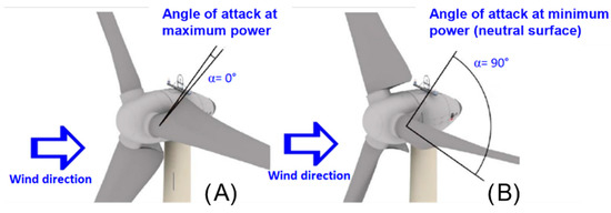
Figure 2.
Angle of attack at maximum power (A), angle of attack at zero power (B) [13].
2. Wind Power Plant, Wind, and Wind Energy
Wind energy is currently one of the most widely used renewable sources. At present, we can say that wind energy is experiencing a rise at the global level. The largest source of wind energy is the open sea (offshore) [10,14]. It has no barriers, so the wind flow is continuous and at a higher speed compared to the mainland. Offshore power plants can generate 50% more energy than onshore wind power plants. The advantages of a wind power plant are that it does not emit any CO2 emissions into the air, its waste production during operation is zero, it is easy to maintain, and it has a long service life. Its disadvantages include high investment costs, potential noise during operation, intermittent power generation, and the production of electricity alone [15]. The wind power plant also has its limitations, and these are e.g., the necessary availability of a construction site for heavy machinery, high investments in the distribution network, and the need for special wind intensity [16].
In the past, the wind was qualitatively characterized using the Beaufort scale shown in Table 1. It is still used today. This scale describes the wind speed based on visual diagnostics. No measuring instruments need to be used [17,18].

Table 1.
Beaufort wind scale.
2.1. Hydraulic PITCH System
In this case, the rotation is provided by pumps (Figure 3 and Figure 4). The pumps generate the required pressure, which acts on the hydraulic piston. This piston is firmly connected to the inner part of the blade [19,20]. By extending or retracting the piston into the cylinder, the angle of attack of the blade changes. The system is controlled by valves with built-in intelligence and digital communication. These control systems increase turbine performance and improve remote diagnostics. The pump and motor are usually mounted in a nacelle with hydraulic pistons mounted in the hub. The hydraulic pitch system is suitable if frequent and stronger turning of the angle of attack is required [21,22].
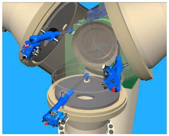
Figure 3.
Construction of the hydraulic blade rotation system [23].

Figure 4.
Principle of operation of the hydraulic blade rotation system [24].
The hydraulic pitch system is a proven and safe technology that has been used for much longer than other systems, and provides highly reliable control of the blade inclination. It offers a very long service life for the hydraulic system and high resistance to vibration and thermal stress [23].
The system includes a hydraulic drive, linear transducer (built-in drive), shaft, bearing system for the drive, swivel distributor including valves, pressure line (distribution system), pressure line holder, coil spring, vane angle sensor, swivel coupling, hoses located in the rotor hub and in the nacelle, and many other devices [13,24].
The advantages of this system include:
Accuracy, sufficient torque (proportional to system pressure), simple pressure control, turning speed (response time of valves and hydraulic actuators is measured in milliseconds), protection against high wind loads, secured optimization in power generation, limited maximum power, and powerful circular rotation of blades (for large turbines) [25].
There are many factors why it is advisable to use a hydraulic swivel system. It is suitable for all climatic conditions. The connection to the system is flexible. The emergency stop works even without a power supply thanks to a coil spring incorporated in the hydraulic system, which stores the energy needed to turn the blades to the zero position in the event of a fault. Status monitoring is relatively simple [13,24]. Its hydraulic system is structurally uncomplicated, which makes maintenance low. The hydraulic system is generally cheaper throughout its service life (investment costs, maintenance, and service costs) [26].
With hydraulic pitch shooting, there are not only advantages but also disadvantages, among which are:
A high degree of cleanliness is required during service and replacement of parts in the equipment.
Leaks can occur in the circuit (this can be prevented by selecting the right components, regular service, and maintenance), and possible risk to the environment due to hydraulic fluid leakage [13,24].
As mentioned in the introduction, the solved cases will be implemented due to strong winds. But how can we define the term “strong wind” for the public? It is Table 1, which describes the Beaufort wind scale, that provides a simple insight and description of what the different wind levels represent. In this case, strong winds provide a level of 9 to 11 on the Beaufort wind scale. For this reason, we have determined a wind speed of 27 m/s, which represents the midpoint of this range and corresponds to a level of 10.
2.2. Electric Pitch System
With the electric pitch blade rotation system (Figure 5 and Figure 6), rotation is ensured by a DC motor. Typical of this system is that there is only one turning motor on each blade. The engine has a large torque, with which it moves the blades along the individual teeth. In the event of an emergency or breakdown, charged batteries or ultra-capacitors rotate the turbine blades under load to the zero (neutral) position [24].
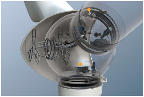
Figure 5.
Construction of an electrical system for turning blades [27].

Figure 6.
Construction of an electrical system for turning blades [27].
It includes, e.g., servomotor with brake, servomotor sensor, gearbox housing, electrical switches, mechanical stop, gear wheel on a paddle bearing, gear wheel on a gearbox, gear wheel lubrication system, batteries, battery holder, battery monitoring system, heating system (for cold climates), angle of attack sensor, etc. [24].
The advantages of this system include:
- No hydraulic fluid is used (zero load for the environment);
- Lower energy consumption (relative to the hydraulic system).
There are the following problems and disadvantages when using an electric pitch system:
- Battery problems: demanding condition monitoring, low performance at low temperature, frequent need for replacement (every two to three years);
- The problem of inadequate lubrication of gears due to small displacements requires a very complex solution that consists of many components, complex wiring, fault repair is challenging;
- The problem between clearances in gears [27].
2.3. Hybrid Pitch System
This turning system is a combination of electric and hydraulic systems. In this case, the change of the angle of attack is ensured by the electrical system, while the safety elements, which prevent damage to the blades and the rotor, are ensured by the hydraulic system [24]. In this case, the risk of hydraulic fluid leakage is rapidly reduced, as the rotation of the blades is performed by an electric motor. This will reduce energy costs [22]. The great advantage of this hybrid system is that operators do not have to worry about batteries, and in the event of their failure, the turbine components are not damaged.
3. Regulation of the Commission of the European Union 2016/631
This is a regulation of the Commission of the European Union (EU), which lays down a network regulation for requirements for the connection of electricity producers to the electricity system [28].
The European Commission has implemented this regulation due to the constant increase in the number of electricity generators connecting to the European electricity grid (ENTSO-E). It is intended to ensure that producers who wish to join the system and are adding significant units meet the required conditions set out in this regulation. The conditions of this regulation shall not be binding on existing electricity generating units and units that are at an advanced stage of planning but have not yet been completed [27]. Of course, the application of the regulation to specific units can be decided by the appropriate regulatory body or EU Member State. It is mainly a matter of being able to integrate producers of electricity from renewable sources into the system. It is therefore necessary that these generators meet the requirements defined in the regulation and can regulate the output of their power plants according to the network load (depending on the network frequency) [29].
The regulation, adopted by the European Commission, consists of Title VII, containing 14 chapters and 72 articles. Below is a brief overview of the content [19]:
Title I—General provisions.
Title II—Requirements.
Title III—Procedure for notification of operations for connection purposes.
Title IV—Conformity.
Title V—Exceptions.
Title VI—Transitional measures for emerging technologies.
Title VII—Final provisions [19].
It also contains the following sections by [19,28]:
- Scope.
- Application to Existing Electricity Generation Units.
- Determination of the importance of an electricity generation unit.
- Application of the regulation to electricity generation.
- Pumped storage plants.
- Industrial sites, and combined heat and power units.
4. Proposal for Regulation of the Power of a Wind Power Plant
4.1. Power Regulation Flow Chart
The power regulation of the wind power plant is ensured by changing the angle of attack (Figure 7). By changing the angle of attack, the area to which the blade is exposed to the wind is adjusted. The angle of attack changes. This is the so-called pitch regulation [30]. The important point is that the rotor blades are turned correctly against the wind direction. This complete process is based on network requirements that are constantly changing.
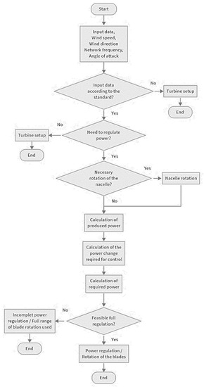
Figure 7.
Flow chart of wind power output regulation [source: author’s archive].
From this information, it follows that to be able to regulate the power, we need the following input data:
- Wind speed;
- Wind direction;
- The current state of the net (i.e., network frequency), and information on the current angle of attack.
Input data in the standard? All input data must be within the specified limits. However, this requirement does not apply to the direction of the wind, because the nacelle only must turn correctly towards it. The frequency of the network must be within the tolerances allowed and must not exceed the specified limits. The mains frequency should theoretically be constantly at 50 Hz. The frequency value required is 50 ± 0.02 Hz. This deviation is due to the insensitivity of the turbine controllers [31]. A change in frequency can occur if there are faults in the system, whether on the consumption or resource side. It is precisely for these cases that strict criteria and requirements are set to regulate the balance between production and consumption. Therefore, wind farms also need to be able to regulate their output according to network requirements. Another input that we need to know for the power control to run properly is the angle of attack. The angle of attack is the most important factor by which the power can be regulated. Data on the current angle of attack are obtained from sensors that are installed on the blades.
Turbine adjustment. The last input data, the use of which is conditioned by its current parameters, is the wind speed. Current data on wind speed and direction are obtained from the weather unit measured on the outer cover of the nacelle. The higher the turbine above the earth’s surface, and the farther from the land, the higher the speed of the turbine, and so the more likely wind farms will be built mainly at sea (offshore) and at the highest possible height. Therefore, in order for a wind turbine to be able to obtain energy from the wind and use this energy to generate electricity, a certain speed is needed [17,32]. This minimum required speed is approximately 3 m/s. In this case, it is the lower limit. If the wind speed is lower than 3 m/s, the wind energy is not sufficient to rotate the rotor of the wind turbine and thus also to produce electricity. The wind turbine rotor stands or moves only very slowly. The upper limit, which the wind speed should not exceed to use the wind energy, is approximately 30 m/s. If the wind speed exceeds this limit, the wind becomes dangerous for the wind turbine. In this case, there are two possibilities. The first option is a situation where the rotor blades rotate automatically or manually to the neutral position. In this position, the turbine rotor stands or moves only very slowly [13]. This position serves as protection against damage to the rotor blades, turbine, and possibly also the collapse of the wind farm. The neutral position is shown in Figure 2. The second option is for the rotor blades to rotate at angles that would ensure the safe continuation of electricity production. This possibility is the subject of laboratory and practical research by companies engaged in the production of wind power plants. In this case, several factors need to be considered, such as the mechanical strength of the rotor blades, as well as the mechanical strength and strength of the blade and nacelle rotation systems.
Need to regulate power? If the control unit evaluates all input data as satisfactory, it is possible to move further in the control process. At this point, the control unit must evaluate whether the power needs to be regulated. This evaluation is based on a comparison of the network frequency to a prescribed value. If the control unit detects an illegal deviation, i.e., the difference between the mains frequency and the specified frequency values, it is necessary to proceed to power control.
Production without regulation. If the control unit evaluates that the mains frequency is within the prescribed values, it sends a signal to the turbine that no power control is needed at this time, and the electricity production continues without control.
Need to turn the nacelle? Power regulation begins by instructing the wind turbine control unit to deflect the nacelle so that the nacelle rotates correctly in the wind direction. If the nacelle rotation sensors detect the correct position in relation to the wind direction from the weather measuring unit, it is not necessary to rotate the nacelle.
Nacelle rotation. If the sensors sensing the rotation of the nacelle detect an incorrect rotation in the wind direction from the weather measuring device, the electric motors of the deflection device are instructed by the controller (nacelle rotation control unit) to rotate the nacelle correctly in the wind direction [33]. This step is not possible before the question “Need to regulate power?”, because if the turbine power did not need to be regulated, but the rotation of the nacelle against the wind was a little off, the power would need to be regulated automatically after the rotation of the nacelle against the wind.
Calculation of produced power. If the direction of rotation of the nacelle is correct for the wind direction, the control unit can calculate the actual power produced by the turbine. The power produced by the turbine can be determined from the power characteristics. The power characteristic is the dependence of the produced power on the angle of attack at a certain wind speed. These performance characteristics are determined by each wind power company in its own laboratories or in practice. Experiments can be carried out in a wind tunnel on a reduced copy or through simulation in special computer programs. Performance characteristics are the know-how of every company and are not publicly available [28,34]. The wind turbine rotor blades can change their angle of rotation from 0° to 90°. Marking the maximum and minimum of performance is a personal matter. The maximum rotation and maximum power can be 0° when rotating. The turbine reaches the minimum rotation and zero power when rotating the blades at an angle of 90°. But it can also be the other way around. It depends on the designation of the starting point. Theoretically, the performance characteristic can be linear, but in practice, the performance characteristic is likely to be nonlinear. [9].
4.2. Power Regulation of Wind Power Plants in a Computer Program
To get a correct idea of how the regulation of the wind turbine power by turning the angle of attack should work in principle, a program was prepared. The program was created in the MATLAB application (Figure 8). This program can also be created in other applications.
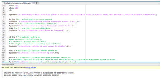
Figure 8.
MATLAB application environment-calculations [source: author’s archive].
Calculation of the power change required for regulation. If the power produced by the wind turbine is known, it is necessary to calculate the required power change to regulate the frequency using the input data. First, the control unit calculates the auxiliary quantities needed to calculate the required power change. It is necessary to calculate the power number of the power plant λ. To calculate the power number λ, it is necessary to use the data on the statics of the wind power plant, the current production in MW (power), and the prescribed frequency of 50 Hz. The power number λ is calculated according to the relationship [35]:
The next step of the control unit is to calculate the difference between the nominal frequency and the mains frequency.
As a last step, the control unit calculates the required power change to regulate the system.
Based on the calculated results, the control unit decides whether the turbine output needs to be reduced or increased. If the power change ∆Pe is positive, the power must be increased. If the power change ∆Pe is negative, the power must be reduced.
Calculation of required power. This means that the control unit calculates the required power, which guarantees the regulation of the system, and thus the change of frequency to the nominal value of 50 Hz.
If the result of the power change ∆Pe is positive, the resulting required power PPe will be higher than the currently produced power Pe, which means that it is necessary to increase the power. If the result of the power change ∆Pe is negative, the resulting required power PPe will be lower than the currently produced power Pe, which means that it is necessary to reduce the power.
Feasible full regulation? The control unit uses the relationship to calculate whether the required power change (regulation) can be performed in full under the current settings and conditions. There are two ways in which the control unit determines the free range required for regulation.
If ∆Pe is positive, the required PPe power must not exceed the maximum possible power output under current weather conditions.
If ∆Pe is negative, the required PPe power must not exceed the minimum possible power output under current weather conditions.
Incomplete power control or the entire range of blade rotation is employed. If these conditions are not met, it means that full power control cannot be performed. The control unit directs the blade rotation system for partial or complete control. Should such a situation arise, it is necessary for several wind farms, or the entire wind farm, to be interconnected and to communicate with each other. Then, if the regulation of one wind power plant is incomplete, it will be possible to adjust the power in the network by means of another wind power plant connected to the network. The given situation of incomplete regulation can be observed in Example No. 3.
Power regulation/Blade rotation. If the control unit evaluates that full power control is possible, it recalculates the change in the angle of attack according to the defined power characteristics. According to the set sensitivity, the control unit calculates how much power falls on one division of the blade (the division can be 1°, but also 0.1°; it depends on the conversion) [3,4]. After converting the required power change to the angle of attack, the control unit sends a command to the blade rotation system to rotate the rotor blades to the new, desired position. The situation of complete power regulation can be observed in Example No. 1, where the power is increased, and in Example No. 2, in which the power produced is reduced [7,9].
5. Procedure for Calculating the Power Regulation in the Program
- step
Parameters and values that are fixed and included in the program are entered or modified:
- The mains frequency is equal to the required frequency, which is fn = 50 Hz.
- Turbine power characteristics (dependence of turbine power on the angle of attack):
- >
- The program clearly defines the characteristics, which are created based on the values we have chosen.
- >
- The performance characteristics that govern the program are not based on actual values and measurements from practice. More than 30 companies from all over the world that deal with the production and fabrication of wind power plants were contacted, but no company provided any data on the dependence of power on the angle of attack. It is their know-how, and this data is not publicly available. Therefore, performance characteristics were developed and implemented into the program (Figure 9).
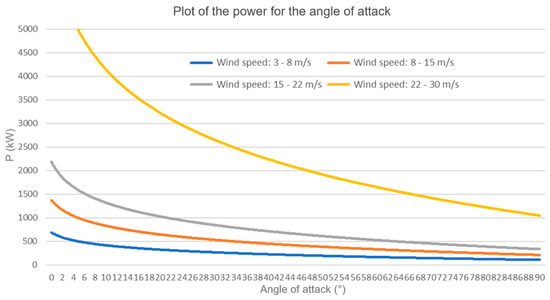 Figure 9. Graphical dependence of turbine power on the angle of attack [source: author’s archive].
 - >
- The power characteristics are intended only for a basic demonstration of how the regulation of the power of a wind power plant by changing the angle of attack.
- >
- Four performance characteristics are created, according to which the program is controlled; each power characteristic is designed for different wind speed ranges.
- >
- If wind speed (RV): 0 m/s ≤ RV < 3 m/s-wind speed is too low, turbine is standing = does not produce any power
- >
- If the wind speed (RV): 3 m/s ≤ RV < 8 m/s-the maximum possible produced power is 500 kW.
- >
- If the wind speed (RV): 8 m/s ≤ RV < 15 m/s-the maximum possible produced power is 1000 kW.
- >
- If the wind speed (RV): 15 m/s ≤ RV < 22 m/s-the maximum possible produced power is 1600 kW.
- >
- If the wind speed (RV): 22 m/s ≤ RV ≤ 30 m/s-the maximum possible produced power is 5000 kW.
- >
- If the wind speed (RV) is: 30 m/s < RV-the wind speed is too high, there is a risk of damage to the turbine; the turbine blades rotate manually or automatically to the neutral position, where the turbine stops and will not produce any power.
- 2.
- step
The necessary parameters are entered in the program. These parameters are basic, and are used to determine the parameters of the turbine. All entered parameters with which the wind turbine works are current. For example, mast height, nacelle size, blade size, generator power and parameters, etc. are not specified:
- Actual network frequency = current network frequency = fs (Hz):
- >
- Any frequency value, such as 49.8 Hz or 50.3 Hz, can be entered.
- Statics of a wind power plant = S (%):
- >
- Any statics value can be entered e.g., 4%; 6%.
- Rotation of the turbine/nacelle in relation to the wind direction = NT (%):
- >
- The value of the turbine/nacelle rotation can be entered from 0% (rotation 0% means that the nacelle is rotated correctly in the wind direction) to 180% (rotation 180% means that the nacelle is rotated maximally incorrectly in the wind direction).
- Wind speed = RV (m/s):
- >
- A wind speed value of only 3 m/s (inclusive) to 30 m/s (inclusive) can be entered. If a wind speed below 3 m/s is entered, the turbine is stopped because the wind speed is insufficient for production. If a wind speed above 30 m/s is entered, the blades automatically rotate to the neutral/off position to prevent damage to the wind turbine. In this case, the wind turbine does not produce any power.
- >
- A wind speed of up to 3 m/s can be entered (the lowest speed at which the wind turbine can supply power to the grid).
- Rotation of the blades = NL (%):
- >
- The value of the angle of attack can be entered between 0% (the angle of attack is rotated as best as possible and produces maximum power) and 90% (the blade angle is rotated to the off position, i.e., the wind turbine is standing and producing no power).
- 3.
- step
These values are then calculated in the program according to the entered parameters:
- Current performance = P (kW):
- >
- Power produced by the turbine according to the specified parameters, determined by the performance characteristics of the wind turbine, is given in kW for more detailed, visible power changes.
- Wind turbine power number = Lambda (MW/Hz).
- Difference between the nominal value of the frequency fn (Hz) and the actual value of the mains frequency fs (Hz).
- Required power change = dP (kW):
- >
- Required power change to be performed for the actual mains frequency fs (Hz) to reach the required, i.e., nominal value of 50 Hz.
- >
- The power change is calculated/determined from the frequency difference df (Hz) using the formulas in the program.
- Total power after power change = Pc (kW):
- >
- If it is necessary to reduce the frequency, the required power change dP (kW) is deducted from the current power P (kW).
- >
- If it is necessary to increase the frequency, the required power change dP (kW) is added to the current power P (kW).
- Final rotation of the turbine blades:
- >
- The program converts the required change of power dP (kW) to the change of the angle of attack [%] according to the entered power characteristics.
- >
- If it is necessary to reduce the frequency, the calculated change in the angle of the NL blades (%) is added to the current rotation of the NL blades (%).
- >
- If it is necessary to increase the frequency, the calculated change in the angle of attack NLu (%) is deducted from the current rotation of the blades Nlu (%).
6. Examples and Results for the Calculation of the Program
- Example No. 1
The first example solves the case when the network frequency is insufficient (fs = 49.5 Hz, i.e., below the specified level fn = 50 Hz). Then the wind turbine control must register the deviation and start turning and changing the angle of attack. It is necessary to increase the power by the value calculated by the program, and thus change the angle of attack so that the turbine can produce higher power. In the output it is possible to check the entered parameters, according to that which the program calculates, and to get acquainted with the results of the regulation.
Fixed values written in the program:
The mains frequency is equal to the required frequency, which is fn = 50 Hz.
Turbine power characteristics (dependence of turbine power on angle of attack for wind speed) (RV): 22 m/s ≤ RV ≤ 30 m/s with a maximum possible produced power of 5000 kW).
Optional values required for power control calculations:
Actual mains frequency = current mains frequency = 49.5 Hz.
Wind power statics = 4%.
Turbine/nacelle rotation relative to wind = 96°.
The current wind speed = 27 m/s.
The actual turbine blade rotation = 34°.
Power control–calculated values:
It is necessary to turn the turbine in the wind direction by exactly 96°.
Wind power plant power number = 1.55555 MW/Hz.
The turbine’s actual power output is 3111.1 kW.
The difference between required and actual frequency = 0.5 Hz.
Change in power required, increase = 777.775 kW.
After the increase, the final power is 3808.88 kW.
The turning angle of attack after power regulation = 20°.
In Figure 10, the wind turbine blade rotation system can be observed in operation.
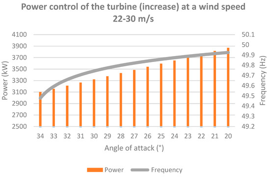
Figure 10.
Graphical dependence of power regulation—increasing [source: author’s archive].
Thanks to its work, it is possible to regulate the power of the wind power plant according to the requirements of the network. On the left side of the graphic dependence, there is a vertical main axis with power values (kW). This axis shows the current size of the power produced by the wind turbine. On the right side of the graphic dependence, there is a vertical minor axis with frequency values (Hz). This minor axis shows the current, i.e., the actual value of the network frequency. At the bottom of the graph is a horizontal axis that shows the angle of attack in degrees (°). The power is shown in the graph by orange bars, and its size can be read from the main vertical axis on the left. The frequency is shown in the graph by a grey line, and its magnitude can be read from the minor vertical axis on the right. At the current wind speed of 27 m/s, the turbine produces a power of 3111.1 kW. In this case, the angle of attack is 34°. In the current situation in the network, when the frequency is 49.5 Hz, it is necessary to increase this power by the required value. This value equals 777.775 kW in this case. Performance increases due to low network frequency. It is necessary for the wind power plant to regulate its power and for the value of the frequency to increase by 0.5 Hz to 50 Hz. The power plant output must be increased until the frequency is equal to 50 Hz. At the same time, it is possible to observe how the size of the power produced changes as the angle of attack changes. The more the angle of attack decreases, the more the production of power increases, and the more naturally the frequency of the network increases. Power regulation stops at 3888.88 kW, when the frequency is at the required value of 50 Hz. The angle of attack is rotated to a value of 20°. Wind power regulation is complete.
- Example No. 2
In the second example, the opposite case is solved, namely when the network frequency is too high, fs = 50.2 Hz, i.e., above the set level fn = 50 Hz. When the deviation is registered, the regulation of the wind power plant must start with the rotation and change of the angle of attack. In this case, it is necessary to reduce the power by the calculated value, i.e., to change the angle of attack so that the turbine can reduce the produced power. In the output, it is possible to check the entered parameters, according to which the program calculates, and to get acquainted with the results of the regulation. The filming process is shown in Figure 11.
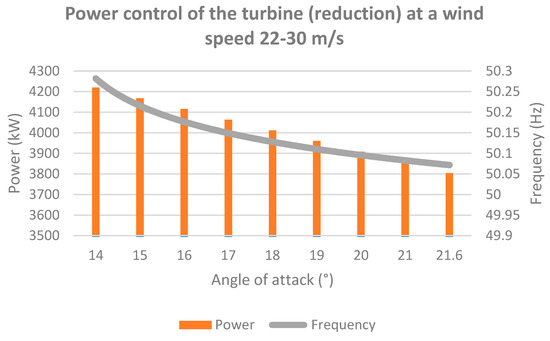
Figure 11.
Graphical dependence of power regulation–reduction [source: author’s archive].
In Figure 11, the wind turbine blade rotation system can be observed in operation. Thanks to its work, it is possible to regulate the power of the wind power plant according to the requirements of the network. The axes of the graphic dependence are marked in this case in the same way as in the previous example. Also, the power and frequency designations are shown in the graph in the same colors.
At the current wind speed of 27 m/s, the turbine produces power of 4222.2 kW. In this case, the angle of attack is 14°. In the current situation in the network, where the frequency is 50.2 Hz, this power must be reduced by the required value. This value is 422.22 kW in this case. Performance decreases due to the high network frequency. The wind farm needs to regulate its power, and the frequency value is reduced by 0.2 Hz to 50 Hz. The power plant output must be reduced until the frequency is 50 Hz. At the same time, it is possible to observe how the size of the power produced changes as the angle of attack changes. The more the angle of attack increases, the more the production of power decreases and the frequency of the network naturally decreases. The power control stops at 3799.98 kW when the frequency is at the required value of 50 Hz. The angle of attack to 21.6°. Wind power regulation is complete.
- Example No. 3
In the third illustrative example, the situation is solved when the network frequency is fs = 49.8 Hz, which means that it is lower than the nominal frequency fn = 50 Hz. If a deviation is detected, the wind turbine control must start by turning and changing the angle of attack. In this case, the power must be increased by the calculated value. It is necessary to change the angle of attack so that the turbine can increase the output. In the output, it is possible to check the entered parameters according to which the program calculates and get acquainted with the results of the regulation. The filming process is shown in Figure 12. This example is specific in that the power control will not be complete due to the maximum range used.
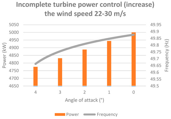
Figure 12.
Graphical dependence of incomplete power regulation—increasing [source: author’s archive].
In Figure 12, the wind turbine blade rotation system can be observed in operation. Thanks to its work, it is possible to regulate the power of the wind farm according to the requirements of the network. The axes of the graphic dependence are marked in this case in the same way as in the previous example. Also, the power and frequency designations are shown in the graph in the same colors. At the current wind speed of 27 m/s, the turbine produces a power of 4777.7 kW. The angle of attack is, in this case, equal to 4°. In the current situation in the network, when the frequency is 49.8 Hz, it is necessary to increase this power by the required value. This value is 477.77 kW in this case. Performance increases due to insufficient network frequency. It is necessary for the wind power plant to regulate its power and for the value of the frequency to increase by 0.2 Hz to 50 Hz. The power plant output must be increased until the frequency is equal to 50 Hz. In this case, a situation arises where it is not possible to completely regulate the power plant’s output.
From the evaluation of the calculated values, it can be stated that the sum of the value of the current produced power and the necessary change of power to regulate the network frequency (4777.7 kW + 477.77 kW = 5255.47 kW) is greater than the maximum possible produced power of 5000 kW. It follows that the rotor blades would need to be rotated by more than 4°, which is also more than the extreme limit of rotation. In this case, the power control stops at a maximum value of 5000 kW, when the angle of attack is 0°. The regulated power has a value of only 222.3 kW. It is not possible to adjust the mains frequency to the prescribed value of 50 Hz. Wind power regulation is incomplete. The graph of incomplete regulation is shown in Figure 12. At this point, it is necessary that several wind power plants are interconnected, which would communicate with each other and be able to regulate the remaining power in the network.
7. Conclusions and Recommendations for Practice
The subject of the work was the creation of a design for wind power control through a system of rotating rotor blades and the creation of a computer program to demonstrate power control in practice under precisely determined weather conditions [6]. The power control design was created using a flowchart. When constructing the flowchart of the control, formulas were used to calculate the change in power depending on the mains frequency and its subsequent conversion to the degrees by which the rotor blade is to rotate. The computer program was created in the MATLAB application. Graphical dependencies were created from the simulation results, showing how the power regulation of the wind power plant works. The output of a wind power plant can be reduced but also increased according to network requirements. Power control by rotating the rotor blades is essential for the grid and electricity generation [36]. It is certain that the power regulation would be most appropriate if it were implemented at as many wind power plants as possible in the shortest amount of time. Depending on the environment and climate in which the wind farm will operate, it is possible to use a suitable blade rotation system according to its advantages and disadvantages. There are several alternatives to choose from, namely an electric, hydraulic, or hybrid system [37]. The blade swivel system needs to respond to changes in frequency and regulate power with sufficient speed, accuracy, and in all conditions.
The creation of the design (flow chart) and the power control program brought positive results, but at the same time showed other possibilities and ambiguities in the use of this technology [38]. The power control simulation in the computer program does not consider interconnection and power regulation at several wind power plants simultaneously. Also, the power characteristics, which describe the dependence of the actual power on the angle of attack, are not based on actual measurements, as it was not possible to obtain these values [22,39]. The newly developed algorithm should be further extended for use in a wind farm; however, before that it would be advisable to correct the data used for a specific wind turbine according to the measurements from practice. For better and more accurate power control results, it would be appropriate to perform a simulation on a specific type of wind farm with the relevant parameters and with the actual power characteristics.
It should be noted that the use of wind power plants to dilute the frequency of the grid can also have a positive impact on the surrounding environment due to the limitation of the power output, which will also reduce the intensity of the noise generated.
The regulation of the performance of new production units, which are considered significant, is described in the Regulation of the Commission of the European Union 2016/631. Due to the growing expansion of wind power plants in Europe and around the world, it is necessary to implement power regulation in practice. If the regulation of power from renewable sources, whether it is electricity produced from wind, solar radiation, or another renewable source, is not introduced, and does not start to be used, a significant problem may arise with the balance of power in the system, i.e., the balance between production and consumption. This problem may become a reality in a few years if renewable power control technologies are not put into practice. For a better idea, we can mention the situation that may occur soon. At a given moment, only one third of the total electricity production will be generated, for example, from nuclear, hydro, or thermal power plants, and the remaining two thirds will be generated by electricity production from wind and solar power plants. In this case, there are two types of problems. The first is a way to ensure that the total production of power in the system is sufficient and covers demand, as one does not know how to control the weather, and thus say exactly at what time a given amount of power will be produced [40]. The second problem is to ensure that the total production of power in the system is not excessive and does not exceed the permitted limits. Even in this situation, it is not possible to predict specific values of the power produced at a given point in time. Fortunately, the development of weather forecasting has advanced considerably in recent years, especially in cloud and wind speed prediction.
In theory, there may be a sunny day across Europe without any clouds in the sky [28]. In that case, solar power plants in Europe will produce maximum output. At the same time, the wind will be strong enough on the same day throughout Europe and the coasts of Europe for wind farms to produce maximum power. The question is: “What about this excess power?” There would be no one to take it, and that would be a problem for the system, as the balance in the system must always be maintained [41]. Therefore, it is necessary and desirable that the output, not only of wind power plants but also of all other power plants, be regulated. It is equally important the power source regulators consider the EU Regulation 2016/631 so that they can also participate in the management of the system. It is therefore necessary to point out such a fact and apply a remedy. The proposed algorithm still requires further development for application to the whole wind farm.
Author Contributions
Conceptualization, Z.Č.; methodology, Ľ.B.; software, Z.Č.; validation, Z.Č. and Ľ.B.; formal analysis, J.P. and M.P.; investigation, Z.Č., P.H. and J.P.; resources, Ľ.B.; data curation, Z.Č.; writing—original draft preparation, Z.Č.; writing—review and editing, Z.Č., M.P. and R.Š.; visualization, P.H. and J.P.; supervision, Ľ.B.; project administration, Z.Č.; funding acquisition, Z.Č. All authors have read and agreed to the published version of the manuscript.
Funding
This work was supported by the Slovak Research and Development Agency under the contract No. APVV-19-0576 and the Ministry of Education, Science, Research and Sport of the Slovak Republic and the Slovak Academy of Sciences under the contract No. VEGA 1/0757/21.
Data Availability Statement
Not applicable.
Conflicts of Interest
The authors declare no conflict of interest.
Nomenclature
| ARMA | Auto Regressive Moving Average |
| CM | Condition monitoring |
| NMPC | Nonlinear Model Predictive Controller |
| VSWT | Variable-Speed Wind Turbine |
| WHO | The World Health Organization |
| α | Angle of attack |
| ° | Degree sign |
| EU | European Union |
| ENTSO-e | European electricity grid |
| Power number | |
| Statics of the generator | |
| Nominal frequency | |
| Currently produced power | |
| Frequency change | |
| Mains frequency | |
| Power change | |
| Required power | |
| Maximum possible power | |
| Minimum possible power |
References
- Sethi, J.K.; Deb, D.; Malakar, M. Modeling of a wind turbine farm in presence of wake interactions. In Proceedings of the IEEE 2011 International Conference on Energy, Automation, and Signal (ICEAS), Bhubaneswar, India, 28–30 December 2011. [Google Scholar] [CrossRef]
- IFM Electronic AB. Wind Turbine with Gearbox. 2017. Available online: http://eval.ifm-electronic.com/ifms/web/apps-by-industry/cat_060_020_010.html (accessed on 1 May 2020).
- Jia, L.; Hao, J.; Hall, J.; Nejadkhaki, H.K.; Wang, G.; Yan, Y.; Sun, M. A reinforcement learning based blade twist angle distribution searching method for optimizing wind turbine energy power. Energy 2021, 215, 119148. [Google Scholar] [CrossRef]
- Patel, P.; Shandilya, A.; Deb, D. Optimized hybrid wind power generation with forecasting algorithms and battery life considerations. In Proceedings of the IEEE 2017 IEEE Power and Energy Conference at Illinois (PECI), Champaign, IL, USA, 23–24 February 2017. [Google Scholar] [CrossRef]
- Dhiman, H.S.; Deb, D.; Carroll, J.; Muresan, V.; Unguresan, M.-L. Wind Turbine Gearbox Condition Monitoring Based on Class of Support Vector Regression Models and Residual Analysis. Sensors 2020, 20, 6742. [Google Scholar] [CrossRef] [PubMed]
- El-Baklish, S.K.; El-Badawy, A.A.; Frison, G.; Diehl, M. Nonlinear model predictive pitch control of aero-elastic wind turbine blades. Renew. Energy 2020, 161, 777–791. [Google Scholar] [CrossRef]
- Bhowon, A.; Khaled, M.A.-A.-E.; Adonis, M. Variable-Speed Wind Turbines for Grid Frequency Support: A Systematic Literature Review. Mathematics 2022, 10, 3586. [Google Scholar] [CrossRef]
- Mariano, A. Wind Turbine Noise Pollution. 2019. Available online: https://www.pagerpower.com/news/wind-turbine-noise-pollution/ (accessed on 24 September 2019).
- Botelho, A.; Arezes, P.; Bernardo, C.; Dias, H.; Pinto, L.M.C. Effect of Wind Farm Noise on Local Residents’ Decision to Adopt Mitigation Measures. Int. J. Environ. Res. Public Health 2017, 14, 753. [Google Scholar] [CrossRef] [PubMed]
- Kolcun, M.; Džmura, J.; Mešter, M.; Pavlík, M. Elektrárne; Technical University of Košice: Košice, Slovakia, 2017; p. 202. ISBN 978-80-553-3119-5. [Google Scholar]
- Johnson. Turbine Review. 27 January 2009. Available online: https://wiki.duke.edu/display/wtw/Turbine+review (accessed on 1 May 2020).
- Zhou, D. Control of Power Electronic Converters and Systems || Control of Wind Turbine System; Elsevier: Amsterdam, The Netherlands, 2018. [Google Scholar] [CrossRef]
- Enercon. Technical Description. ID: D0617713-7. 25 January 2019. Available online: http://www.enercon.de (accessed on 1 May 2020).
- Džmura, J. Elektrárne; Učebný Text; Katedra Elektroenergetiky, Fakulta Elektrotechniky a Informatiky: Košice, Slovakia, 2011; p. 72. [Google Scholar]
- Quaschning, V. Obnovitelné Zdroje Energií; Stavitel Grada: Praha, Czech Republic, 2010; pp. 165–168, 173–178. ISBN 9788024732503. [Google Scholar]
- Tumová, O.-V. Stav Větrné Energetiky v Evropě a České Republice. V Elektro. 2009. Available online: http://www.odbornecasopisy.cz/res/pdf/38355.pdf (accessed on 1 May 2020).
- Benda, V. Obnovitelné Zdroje Energie, 1. vyd.; Profi Press: Praha, Czech Republic, 2012; ISBN 978-80-86726-48-9. [Google Scholar]
- Kalamen, L. Veterné Turbíny. 2020. Available online: https://www.slideserve.com/graham/vetern-turb-ny (accessed on 1 May 2020).
- Goudarzi, N.; Zhu, W.D. A Review on the Development of Wind Turbine Generators across the World. 20 June 2013. Available online: https://link.springer.com/article/10.1007/s40435-013-0016-y (accessed on 1 May 2020).
- Dvorak, P. Pitch Controls: Electric, Hydraulic, or Something new? 5 June 2009. Available online: https://www.windpowerengineering.com/pitch-controls-electric-hydraulic-or-something-new (accessed on 1 May 2020).
- Pošik, J. Veterné Elektrárne. 3 August 2011. Available online: http://www.posterus.sk/?p=11191 (accessed on 1 May 2020).
- Bywaters, G.; Mattila, P.; Costin, D.; Stowell, J.; John, V.; Hoskins, S.; Lynch, J.; Cole, T.; Cate, A.; Badger, C.; et al. Northern Power NW 1500 Direct-Drive Generator. 2007. Available online: https://www.nrel.gov/docs/fy08osti/40177.pdf (accessed on 1 May 2020).
- Wind Power Works. Pitch Systems of the Future–Under All Climatic Conditions. 1 May 2020. Available online: https://www.fsenergy.com/wp-content/uploads/2017/04/hydraulic-pitch-systems-of-the-future.pdf (accessed on 1 May 2020).
- Geocaching. Ostrý vrch. 8 March 2014. Available online: https://www.geocaching.com/geocache/GC5A5MX_ostry-vrch?guid=1825eb35-6832-41d7-9e89-9146deea4ad8 (accessed on 1 May 2020).
- Kurz Industrial Solutions. What Are the Differences Between Hydraulic and Electric Pitch Systems? 24 June 2020. Available online: https://kurz.com/hydraulics-electric-pitch-systems-differences/ (accessed on 1 May 2020).
- Hansen, P. Modular Towers and the Quest for Stronger Wind. 10 February 2010. Available online: https://www.windpowerengineering.com/modular-towers-and-the-quest-for-stronger-wind/ (accessed on 1 May 2020).
- IFM Electronic Gmbh. Electric Pitch Drive. 2014. Available online: https://www.ifm.com/hr/hr/applications/060/wind-energy.html#/!/content/documents/hr/shared/applications/060/1020/2010/2010 (accessed on 7 October 2022).
- Európska Komisia. Nariadenie Komisie (EÚ) 2016/631. 14 April 2016. Available online: https://eur-lex.europa.eu/legal-content/SK/ALL/?uri=CELEX%3A32016R0631 (accessed on 1 May 2020).
- Kovel. Veterná Elektráreň. 2007. Available online: http://www.kovel.sk/userfiles/news/veterna.pdf (accessed on 1 May 2020).
- Voboril, D. Vetrné Elektrárny—Princip, Rozdelení, Elektrárny v ČR. oEnergetice.cz. 2015. Available online: https://oenergetice.cz/elektrina/vetrne-elektrarny-princip-cinnosti-zakladni-rozdeleni/ (accessed on 1 May 2020).
- Tkáč, J. Veterné Elektrárne s Vertikálnou Osou; Elektroenergetika: Roč, Croatia, 2012; ISSN 1337-6756. [Google Scholar]
- Mhi Vestas. MHI Vestas’ V164-9.5 MW Turbine to be Tested at Clemson University, SC. 27 October 2017. Available online: http://www.offshorewindindustry.com/news/mhi-vestas-v164-95-mw-turbine-to-tested (accessed on 1 May 2020).
- NIDEC. Dedicated Range up to 5 MW. 2019. Available online: https://acim.nidec.com/generators/leroy-somer/products/power-alternators/alternators-for-windturbines (accessed on 1 May 2020).
- Kolcun, M.; Griger, V.; Beňa, Ľ.; Rusnák, J. Prevádzka Elektrizačnej Sústavy; Technická Univerzita v Košiciach: Košice, Slovakia, 2007; p. 202. ISBN 978-80-8073-837-2. [Google Scholar]
- Energy Efficiency & Renewable Energy. The Inside of a Wind Turbine. 2019. Available online: https://www.energy.gov/eere/wind/inside-wind-turbine (accessed on 1 May 2020).
- Wikipedia. Savonius Wind Turbine. 8 November 2017. Available online: https://en.wikipedia.org/wiki/Savonius_wind_turbine (accessed on 1 May 2020).
- Futurewind. Eneco Purchases Electricity Haliade-X Prototype. 17 December 2019. Available online: https://www.futurewind.nl/2019/12/17/eneco-purchases-electricity-haliade-x-prototype/ (accessed on 1 May 2020).
- Škorpík, J. Větrné Turbíny a Ventilátory. 8 July 2019. Available online: https://www.transformacni-technologie.cz/22.html (accessed on 1 May 2020).
- OZE. Veterná Energia. 2018. Available online: http://www.oze.stuba.sk/oze/veterna-energia/ (accessed on 1 May 2020).
- Menet, J.L.; Bourabaa, N. Increase in the Savonius Rotors Efficiency via a Parametric Investigation. January 2004. Available online: https://www.researchgate.net/publication/228957621_Increase_in_the_Savonius_rotors_efficiency_via_a_parametric_investigation (accessed on 1 May 2020).
- Hau, E. Wind Turbines: Fundamentals, Technologies, Application, Economics, 3rd ed.; Springer: New York, NY, USA, 2013; ISBN 978-3-642-27150-2. [Google Scholar]
Publisher’s Note: MDPI stays neutral with regard to jurisdictional claims in published maps and institutional affiliations. |
© 2022 by the authors. Licensee MDPI, Basel, Switzerland. This article is an open access article distributed under the terms and conditions of the Creative Commons Attribution (CC BY) license (https://creativecommons.org/licenses/by/4.0/).