Review

Secondary-Frequency and Voltage-Regulation Control of Multi-Parallel Inverter Microgrid System

1
School of Electronic Information and Electrical Engineering, Shanghai Jiao Tong University, Shanghai 200240, China
2
College of Electrical Engineering, Shanghai University of Electric Power, Shanghai 200090, China
3
Shanghai Xilong Technology Co., Ltd., Shanghai 201109, China
4
Shanghai Chint Power Systems Co., Ltd., Shanghai 201614, China
5
Shanghai Da Yu Informational Tech Co., Ltd., Shanghai 200000, China
*
Author to whom correspondence should be addressed.
Energies 2022, 15(22), 8533; https://doi.org/10.3390/en15228533
Submission received: 8 October 2022 / Revised: 29 October 2022 / Accepted: 9 November 2022 / Published: 15 November 2022
(This article belongs to the Section F: Electrical Engineering)

Abstract

:
As an important form of distributed renewable energy utilization and consumption, the multi-parallel inverter microgrid system works in both an isolated and grid-connected operation mode. Secondary-frequency and voltage-regulation control are very important in solving problems that appears in these systems, such as the distributed secondary-frequency regulation real-time scheme, voltage and reactive power balancing, and the secondary-frequency regulation control under the disturbances and unbalanced conditions of a microgrid system. This paper introduces key technologies related to these issues, such as the consensus algorithm and event-triggered technique, the dynamic and adaptive virtual impedance technique, and the robust and self-anti-disturbance control technique. Research and design methods such as small-signal state-space analysis, the Lyapunov function design method, the impedance analysis method, μ-synthesis design, and the LMI matrix design method are adopted to solve the issues in secondary-frequency regulation and voltage regulation. As the number of inverters increases, the structure of the microgrid becomes more and more complex. Suggestions and prospects for future research are provided to realize control with low-communication technology and a distributed scheme. Finally, for the case study, the droop-control model and primary frequency/voltage deviation of a multi-parallel inverter microgrid system is analyzed, and a state-space model of a multi-parallel inverter microgrid system with a droop-control loop is established. Then, the quantitative relationship between the primary frequency/voltage deviation and the active and reactive power output in the system is discussed. The methods and problems of centralized and decentralized secondary-frequency regulation methods, secondary-frequency regulation methods based on a consensus algorithm and an event-triggered mechanism, reactive power and voltage equalization, power distribution, and small-signal stability of the multiple parallel inverter microgrid system regarding the virtual impedance loop are analyzed.

1. Introduction

The microgrid, which plays an important role in enhancing regional renewable energy use, is important for distributed renewable energy utilization [1,2]. As the main power generator for renewable energy, microgrid inverters are important parts of the microgrid system [3]. At present, a growing number of microgrids are now composed entirely of renewable energy generation equipment and corresponding energy storage equipment [4,5,6]. The operational control of microgrid inverters will therefore be increasingly necessary [7,8].
Microgrid operation includes both grid-connected operation and an islanded operation mode [9]. The current-controlled mode and the voltage-controlled mode are two corresponding control schemes for inverters in a microgrid system [10]. In the grid-connected operation mode, the inverters of the microgrid obtain the voltage and phase angle of the grid through a phase-locked loop, so that in this mode, the voltage and frequency of the microgrid are supported by the main grid to which they are connected. The inverters of the microgrid do not require frequency regulation, but rather only the maximum power output from a renewable energy source [11,12]. In this mode, the inverters all use the current-controlled PQ control scheme. For islanded operation, the voltage frequency within the microgrid needs to be supported by the inverter due to the absence of support from a main grid [13]. Therefore, the frequency and voltage regulation of the microgrid inverter become very important in the islanded operation mode [14,15].
Droop control is the main control method for inverters operating in an islanded microgrid system. By simulating the primary-frequency droop characteristics of synchronous generators, droop control strategy enables multiple inverters that operate together in the same islanded system to spontaneously distribute power at the cost of a corresponding primary voltage frequency deviation [15]. This also leads to the problem of secondary frequency/voltage regulation in multi-parallel inverters. A considerable number of research reviews have analyzed the problems associated with droop control [16,17,18,19,20]. In [16], various common types of droop-control schemes are reviewed, and their respective control effects are compared accordingly. In [17], conventional droop schemes, general droop schemes considering lines, and virtual impedance droop and transient droop schemes are reviewed. Their small-signal stability characteristics are also analyzed in this research. In [18], methods for droop control-based inverters’ small-signal models are reviewed. In [19], the structure of a hierarchical control scheme with droop-control loop is reviewed. The control objectives at each level are additionally analyzed. In [20], various common schemes for enhancing droop control-based inverters’ small-signal stability are reviewed.
In addition, a series of reviews have been carried out in the literature on the frequency and voltage regulation control of droop-control inverters for island operation, addressing numerous other key issues. In [21,22], the applications of model predictive control (MPC) in a microgrid inverter control area are reviewed. In [23], the issue of load-shedding strategies for the independent operation of microgrids during overload events are reviewed. In [24], the difference between a double- and single-ring droop-control scheme are compared in detail in terms of small-signal stability.
This paper analyzes key issues in the control of secondary-frequency and voltage regulation of a multi-parallel inverter microgrid system, such as frequency and voltage regulation, power balancing and operation control under disturbances, and unbalanced load conditions, starting from the basic control methods of the multi-parallel inverter microgrid system. Then, an introduction is presented to the various methods commonly used in such systems, such as virtual impedance methods, consensus algorithms, event-triggered mechanisms, and robust control design methods. A review and evaluation of the methods used in the existing literature is also conducted. The critical problems in the control of secondary frequency and voltage regulation in multiple parallel inverter microgrids are introduced and reviewed in Section 2. The key technologies commonly used to solve such critical problems are introduced and analyzed in Section 3. The typical design process of the event-triggering mechanism-based consensus algorithm for secondary-frequency regulation control strategy using a four-bus independent microgrid is presented in Section 4 as a case study. Section 5 gives the conclusions of the paper.
Figure 1 illustrates the structure of this paper. The issues and techniques discussed in the paper are included.
The contribution of the paper includes the following:
(1) The key issues in secondary-frequency and voltage regulation, including secondary-frequency and voltage regulation methods, as well as adaptivity, power balance, the reactive power droop invalidation problem, and regulation control under non-ideal conditions, are analyzed in detail. Existing research related to these problems is listed and analyzed.
(2) Some commonly used techniques, including the virtual impedance method, a consensus algorithm with an event-triggered mechanism, and active disturbance rejection control, as well as robust H control techniques, are introduced, and their basic principles are analyzed.
(3) A typical design of a secondary-frequency regulation control method using the consensus method with an event-triggered mechanism for a microgrid system is proposed. From the simulation result, the consensus method with the event-triggered mechanism is effective in restoring the secondary-frequency error while creating little communication pressure.

2. Analysis of Key Issues in Secondary-Frequency and Voltage Regulation of Microgrid System

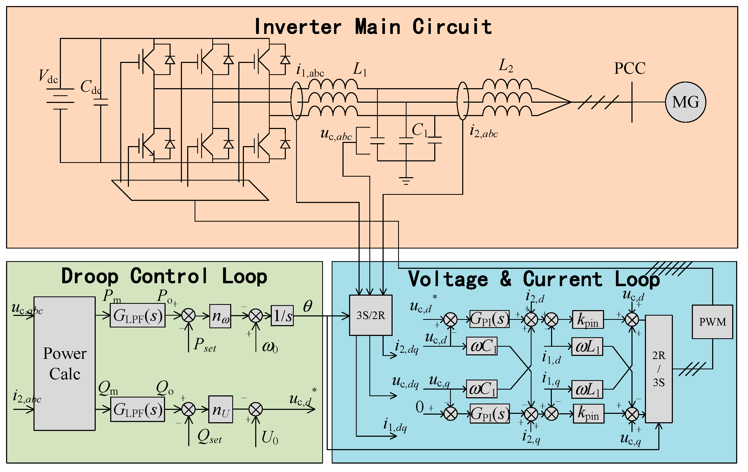
A microgrid system consists of inverters, which adopt a droop-control strategy. The basic control block diagram of a droop-control inverter is shown in Figure 2. The main circuit of the microgrid inverter consists of IGBT bridges, a DC side capacitor, and an LCL filter. The control loop is divided into the inner voltage and the current loop, as well as the droop loop. Since this paper focuses on the secondary-frequency and voltage-regulation problem, the inner control loop is not a main topic. However, it is worth mentioning that the inner voltage and the current loop have a great impact on the stability of the system [11]. In this paper, the droop-control loop is the focus.
According to Figure 2, considering the case of multiple inverters, the droop-control loop is:
{ ω j = ω 0 n ω , j ( P o , j P j set ) u c , d , j * = U 0 n U , j ( Q o , j Q j set )
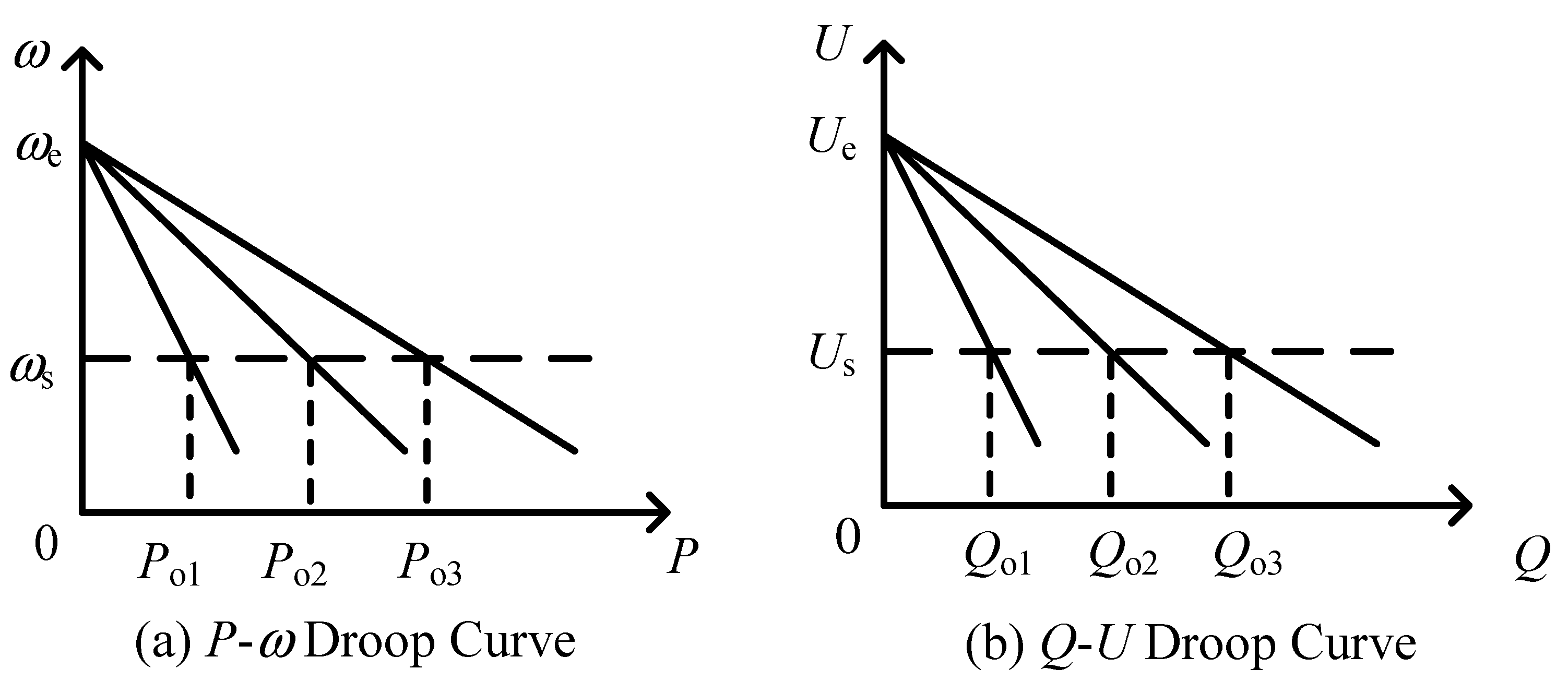
In (1), ωj and uc,d,j* are the j-th inverter output voltage frequency and the d-axis voltage value (amplitude value). ω0 and U0 are droop loop frequency voltage reference values. nω,j and nU,j are the active and reactive droop coefficients of the j-th inverter. Po,j, Qo,j, Pjset, and Qjset are the active and reactive power output and the active and reactive power reference of the corresponding inverter. According to (1), the droop curve can be plotted for multiple inverters operating in parallel. The droop curves are shown in Figure 3.
In Figure 3, ωe and ωs are the intercept frequency and steady-state frequency. Ue and Us are the intercept voltage and steady-state voltage. The droop scheme presented in Equation (1) is called the P-ω and Q-U droop scheme [25,26]. Further, the P-U and Q-ω droop scheme and the P-δ droop scheme [27] are also adopted in research and engineering. The former scheme is mostly used in microgrid systems with significantly resistive lines, whereas the latter scheme requires a separate frequency synchronization module, such as a GPS synchronization device [28]. This paper is based on a typical P-ω and Q-U droop scheme.

2.1. Droop-Based Microgrid Secondary-Frequency and Voltage Regulation

Based on Equation (1), adding the secondary-frequency voltage-regulation term, the droop equation becomes:
{ ω j = ω 0 n ω , j ( P o , j P j set ) + Δ ω j u c , d , j * = U 0 n U , j ( Q o , j Q j set ) + Δ u j
In (2), Δωj and Δuj are the secondary-frequency and voltage-regulation components. According to the droop curve shown in Figure 3, if the inverters connected in the common microgrid system have the same secondary-frequency/voltage-regulation component and, at the same time, the droop curves are shifted up and down by the same value, the steady-state frequency ωs and steady-state voltage Us will move up and down by the same value. The key problem of secondary regulation of the frequency and voltage in multi-parallel inverter microgrids is ensuring that the secondary voltage and frequency-regulation components of each inverter remain at the same value for regulation.
To achieve these regulation requirements, the secondary voltage and frequency-regulation strategy of independently operating multiple-parallel inverter microgrid systems can be divided into three options: centralized, decentralized, and distributed strategies [29]. In a centralized strategy, a dedicated central controller for the microgrid is needed. Distributed generation devices in the system such as inverters upload their information to a central controller and receive control commands from the central controller. The decentralized strategy completely abandons communication, and the inverter relies only on local data information for secondary frequency and voltage regulation. Instead of adding a dedicated central controller for the microgrid, the distributed strategy requires the inverters to pass their own state information along to each other, thereby autonomously equalizing the state information.
For centralized control, the research is usually concerned with the upper dispatching level to achieve voltage and frequency regulation while optimizing the operating costs or profits of microgrids or distributed energy systems in an integrated structure. In [30], the optimization modeling of microgrids is analyzed under a centralized control scheme, and the corresponding optimal power flow (OPF) problem is established and solved based on convex optimization theory. In [31], the central controller provides a common frequency and voltage signal reference system, and each inverter follows the signal provided by the central controller to achieve secondary-frequency regulation. In [32], sliding-mode control is adopted to design a control method for achieving current- and voltage-balanced distribution and dispatch between inverters. This method is also capable of achieving invariance in the distribution effect under unbalanced or strongly harmonic load conditions. In [33], multiple microgrid inverters are divided into the form of multiple master–slave microgrid clusters, and a control method for improving the output-side voltage quality is designed based on conservative power theory. In [34], a centralized microgrid frequency and voltage regulation scheme is designed based on model predictive control, which takes into account both frequency drops and the constraints of energy storage in the microgrid. The advantages of a centralized control scheme are that the control structure of each inverter is very simple, and there is no need to switch between the grid-connected and islanded mode during operation. A droop-control loop is not even necessary in the control loop for microgrid inverters using the centralized strategy. The disadvantage of these systems is that the communication pressure on the central controller is high, and the microgrid system is prone to destabilization and breaking down if the communication between the inverters and the central controller fails.
Decentralized strategies completely abandon communication between inverters or a central controller, instead relying only on local data information for secondary frequency and voltage regulation. The control processes in decentralized systems are often more complex. A decentralized linear quadratic regulator (LQR) method for secondary-frequency regulation was proposed in [35]. It needs to solve a complex LQR optimization problem and is computationally intensive locally. In [36], a decentralized secondary frequency regulation method based on model predictive control is proposed, which is also computationally intensive. In [37], a decentralized secondary-frequency regulation method without communication is proposed, which has to be implemented with a lead compensating link to enhance the stability of the inverter system. The advantage of the decentralized scheme is that it does not require communication, but the disadvantage is that its inner-loop control is generally complex and requires a fixed microgrid structure, and it is generally less stable.
Compared to centralized and decentralized strategies, distributed strategies have gradually become mainstream for the secondary frequency and voltage regulation of multi-parallel inverter microgrid systems in recent years. The consensus algorithm is the dominant method in distributed secondary-frequency/voltage regulation schemes [38]. The principle of this method is described in detail in the following section. Quite extensive research has been conducted on consensus algorithms [39,40,41,42]. Ref. [39] analyzes in detail the effect of a time lag in the consensus algorithm. In [40], a small-signal model of a microgrid with respect to a consensus algorithm is developed. In [41], a hierarchical control model of the microgrid considering the consensus algorithm is developed, and the control objectives and optimization model are presented for each level of the control structure. Ref. [42] gives the overall design method of a consensus algorithm with an event-triggered mechanism for a typical microgrid system for secondary-frequency regulation tasks. The consensus algorithm can effectively solve the problem using a dominant host central controller in the control system in the centralized scheme, but it causes huge communication pressure among inverters.
To summarize the current research in terms of frequency and voltage-regulation problems in multi-parallel inverters, distributed strategies and the achievement of low-communication bandwidth and strong stability are the general trends in this area [43]. Table 1 summarizes the scope of the methods and presents a brief description of the articles listed in the literature in the frequency and voltage secondary regulation control area. Further, the pros and cons of the corresponding research are reviewed in terms of calculation cost, method complexity, and system power sharing, and frequency-regulating accuracy after dynamics are reviewed and compared.
Tertiary optimal control for microgrids usually focuses on the optimal and economical operation problem. It is the highest level of hierarchical control structure. Secondary-frequency and voltage regulation control is the basis of tertiary optimal control. Usually, tertiary strategies have little stability and performance consideration, but the optimal power flow problem, operation planning, and economical operation are considered more by recent research. Refs. [44,45,46,47] focus on tertiary optimal control, and they achieve their goals through various methods. Since this paper focuses mostly on secondary-frequency and voltage control, the tertiary optimal control method will be less of a focus in the following part of the paper.

2.2. Power-Balance Problem from Inverter Grid Impedance Mismatch

According to Equation (1), consider an islanded microgrid with N droop-control inverters in the system. The total load within the system is [Ptotal, Qtotal]. When the system is in a frequency and voltage steady-state situation, the system frequency and PCC voltage are at a constant value for all the inverters.
If the microgrid line voltage drop and power losses are not taken into account, Equation (3) can be obtained:
{ n ω , j ( P o , j P j set ) = const n U , j ( Q o , j Q j set ) = const ,   j = 1 , 2 , , N
Equation (3) shows that the deviation of the inverter’s output power from the reference setting and the droop coefficient are inversely proportional if the microgrid line voltage drop and power losses are not considered under steady-state conditions. At this point, the load constraint is considered as follows:
j = k N P o , k = P total j = k N Q o , k = Q total
Then, the output power of each inverter is the following:
P o , j = 1 n ω , j k = 1 N 1 n ω , k ( P total k = 1 N P k set ) Q o , j = 1 n U , j k = 1 N 1 n U , k ( Q total k = 1 N Q k set )
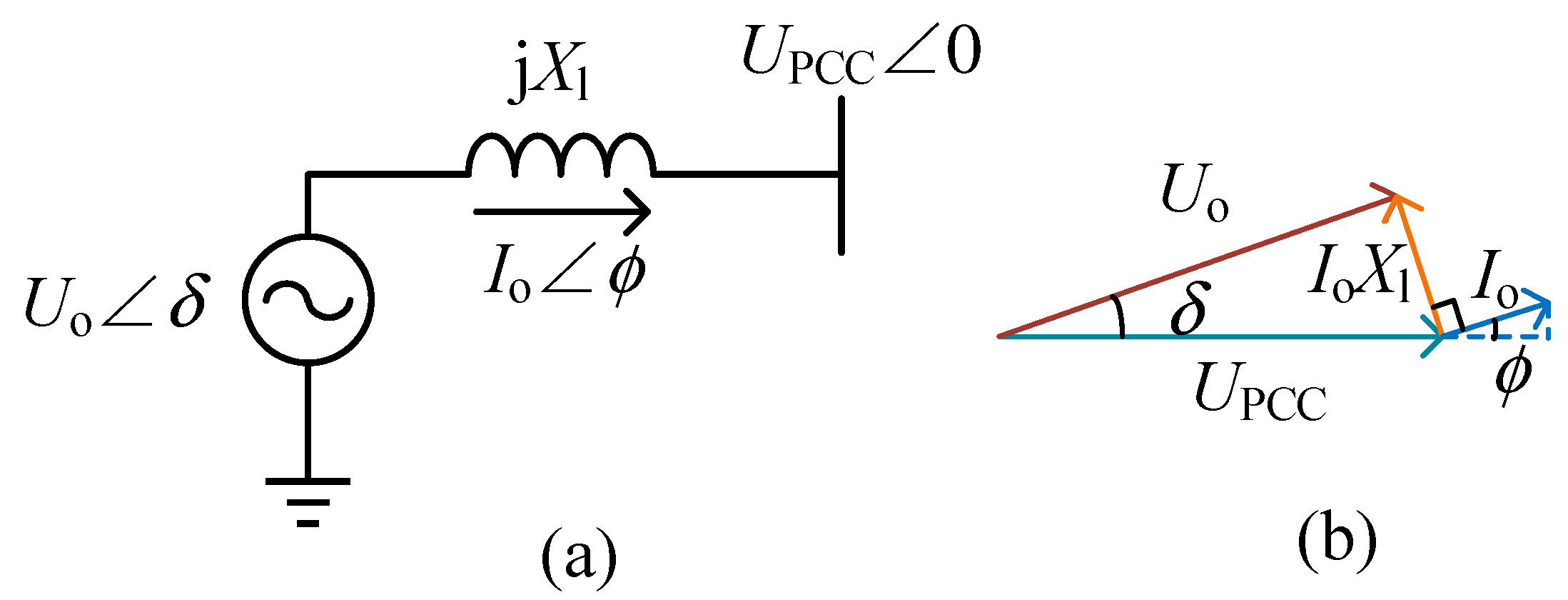
According to Equation (5), the active and reactive power output of each inverter will be inversely proportionally balanced to the coefficient. In practice, however, the desired balanced state of Equation (5) will not be achieved due to the presence of the line voltage drop. Since the active power and frequency are independent state variables, the active power part of Equation (3) can generally be achieved, and the reactive power is generally unable to satisfy the corresponding distribution relationship in Equation (5). A brief analysis of this relationship is presented below. Figure 4 shows the inverter power transfer model. Assume that the feeder line is inductive. Figure 4a is the line diagram when an inverter is connected to the PCC (point of common coupling), and Figure 4b is the phase diagram corresponding to Figure 4a.
Uo is the inverter output port voltage amplitude that satisfies Uo = U0nU(QoQset). According to the phase diagram in Figure 4b, the active and reactive power emitted by the inverter are the following:
P o = U o U PCC X l sin δ Q o = U o ( U o U PCC cos δ ) X l
Changing the reactive term into Equation (6), the expression for the pressure drop in the direction of Uo is obtained as:
U o U PCC cos δ = Q o X l U o
If the pressure drop in the vertical direction is neglected, Equation (8) will be obtained:
U 0 n U ( Q o Q set ) Q o X l U 0 n U ( Q o Q set ) = U PCC
According to Equation (8), the line voltage drop term in the reactive droop can be neglected if the port voltage U0 of the inverter is high or if the line impedance Xl is small, but both conditions are often not satisfied in microgrids consisting of low-voltage inverters, and the reactive droop relationship cannot be maintained if the line voltage drop is not compensated for. If the line voltage drop of each inverter were to fully be compensated, it would not be possible to achieve a consistent voltage among the inverters in the microgrid. The problem of reactive power balance and voltage compensation is therefore a major challenge for microgrid control, and this problem is now starting to receive more and more research attention [48,49].
There are two important ideas for solving the problem of reactive power balancing and voltage compensation. One is to find a compromise between reactive power balancing and voltage compensation [50,51,52]. In [50], an impedance droop scheme is used to solve the problem of accurate reactive power distribution in microgrids. In [51,52], a reactive voltage droop scheme based on the impedance droop is proposed to mitigate the reactive power imbalance caused by the line voltage drop by adding a virtual impedance control that satisfies the droop relationship. However, a certain amount of reactive power imbalance still exists after adopting the above two methods.
The other idea is to discard the reactive droop link and use an additional control loop to achieve reactive power balancing control [53,54]. In [53], a voltage regulation link is designed, and the reactive power balance is achieved by means of a model of predictive control and a consensus algorithm, but the method is complicated. In [54], on the other hand, an integration link is added directly to the reactive power loop to completely limit the reactive power output of each inverter, and the upper control loop performs a separate scheduling control of the reactive power.
At present, neither searching for a balance between reactive power balancing and voltage compensation by compensation nor abandoning the droop-control loop to achieve reactive power regulation and voltage balancing by means of an additional loop has completely solved the problem. Therefore, this issue is still worthy of continued exploration.

2.3. Secondary Regulation Problem under Disturbances, Harmonics, and Unbalance

Microgrid operation and control problems considering small disturbances, harmonics, and unbalance conditions have long been a hot topic of research in the field of microgrid operations and control. The focus of the three non-ideal operating conditions, namely, small disturbances, harmonics, and unbalance, is different.
Disturbances are divided into small and large disturbances. Under the condition of small-signal stability, the system can still remain stable after being affected by small disturbances. Research has focused on system recovery after small disturbances, and research results are available on the frequency and voltage regulation and recovery of microgrid systems under small disturbances [8,55]. Ref. [8] reviews the various forms of small disturbances and the common control methods for disturbance recovery. In [55], a control method with invariance for small disturbances in frequency and voltage is designed by means of a sliding-mode control.
Microgrid inverter mode switching between grid-connected and islanded modes is a common small disturbance that often does not cause system instability during the switching procedure. However, a current shock can be produced during the switching process. Considerable research has been conducted to address the problem of smooth control mode switching [56,57,58,59,60]. An MPC-based control method for single-phase inverters was designed in [56]. A control scheme is designed in the research with four operation modes that include steady-state grid-connected operation, steady-state islanded operation, an islanded-to-grid switching transient procedure, and a grid-connected-to-islanded switching transient mode. The four modes are unified into one MPC objective function, which is the same in form but with different weighting factors in different operation modes. By changing the MPC coefficients during operation, a seamless switching of the four modes of operation is achieved. In [57], a virtual synchronization machine control method with virtual flux linkage control was designed for grid-connected and islanded mode switching. In [58], a perturbation observer is adopted for a seamless switching inverter design. The principle of seamless switching is that the grid-connected and islanded controllers have the same structure, so that only the parameters need to be changed to switch between the grid-connected and islanded mode. In [59], a capacitive current compensation method is proposed to achieve improved stability in the switching procedure.
In addition, some research has also been carried out on small disturbances of the control delay class within the system. In [60], a method for designing microgrid inverter control for uncertain time delays is proposed using an H control scheme. In [61], the phenomenon of consensus algorithm deviation due to time delays in consensus algorithms is avoided by finding a time-delay independent variable and designing a weighted consensus algorithm based on this variable. In [62], the effect of a time delay on the stability of microgrid systems with secondary-frequency/voltage-regulation links based on a small-signal model are analyzed. In [63], a sliding-mode observer is adopted to estimate the control delay of a microgrid inverter, and the time delay is compensated for accordingly. In [64], the impact of microgrids with consensus algorithms under a communication failure is investigated.
Harmonics and imbalances are also common operating conditions in microgrids with multiple parallel inverters [65,66,67]. At present, PR resonance instead of PI control is a common solution for harmonics [66]. Wave traps are also effective for specific harmonics suppression. For unbalanced operating conditions, the symmetric component method is commonly used to extract the unbalanced components, and compensation for the corresponding unbalanced component is achieved accordingly [67]. However, the impact of compensation methods for harmonics and unbalanced conditions on the droop loop and the secondary-frequency and voltage-regulation loop microgrid inverter has been less studied.

3. Key Technologies for Secondary-Frequency and Voltage Regulation of Multi-Parallel Inverter Microgrid Systems and Their New Advances

A number of general analyses and solution techniques have been developed for the current problem of secondary voltage frequency regulation in multi-parallel inverter microgrids. In this section, some of these key technologies are introduced and analyzed in terms of their implementation methods and principles. Development trends of the methods and technologies are also analyzed.

3.1. Virtual Impedance Technique

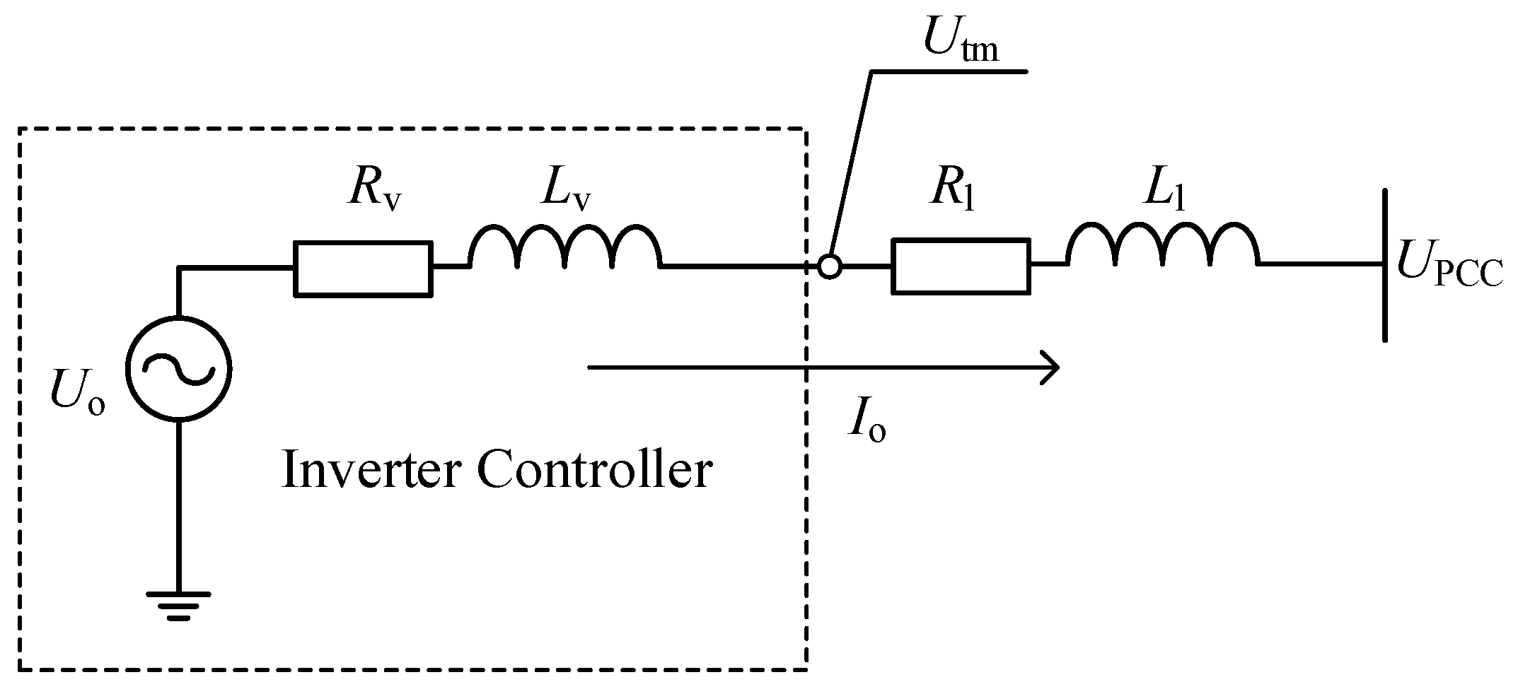
Virtual impedance is a classical method used to improve the stability and reactive power-balancing accuracy of multiple parallel inverter microgrid systems [68]. A schematic diagram of the virtual impedance method is shown in Figure 5.
Rv and Lv are the resistive and inductive parts of the inverter virtual impedance. Utm is the output port voltage, and Io is the inverter output current. The principle of the virtual impedance method is that the output port voltage of the inverter is changed to Utm by virtual impedance loop calculations, as if an equivalent impedance of Rv and Lv is connected in series between the inverter output port and the original output port behind the droop-control loop.
The dq-axis virtual impedance expressions are as follows:
u tm , d q = u o , d q ( R v + L v d d t ω L v ω L v R v + L v d d t ) i o , d q
Since the inverter control inner loop is the decoupled dq-axis PI controller, Equation (9) is commonly used for the implementation of the virtual impedance method. Thus, based on the inner current-voltage control loop illustrated in Figure 2, the virtual impedance control technique can be achieved by changing the reference inputs of the voltage loop from the original uc,d* and 0 to utm,dq.
The key problem with the implementation of Equation (9) is that the differential signal for the output current in it is difficult to realize. Differential calculations will lead to a significant amplification of the signal and numerical noise and should generally be avoided in inverter control loops. There are two main ways to handle the differential calculation issue. One solution is to approximate the differential link as a high-pass filter. Then, the control method in Equation (9) becomes:
u tm , d q = u o , d q ( R v + L v S T hpf S + 1 ω L v ω L v R v + L v S T hpf S + 1 ) i o , d q
The virtual impedance method is defined as transient virtual impedance in [69]. The other solution for differential calculations ignores the dq-axis current differentiation, and the virtual impedance form becomes:
u tm , d q = u o , d q ( R v ω L v ω L v R v ) i o , d q
A significant effect of virtual impedance control is that it can improve the accuracy of droop inverter reactive power distribution. Considering Equation (8), when the line impedance of the system is proportional to the droop coefficient, that becomes:
X l , j X l , k = n U , j n U , k , j , k = 1 , 2 , n , j k
Ignoring the voltage drop due to the reactive droop loop, the Q-U droop relationship will be restored according to Equation (8). Generally, it is difficult to achieve the condition that the line impedance is proportional to the inverter droop coefficient. However, with the virtual impedance control technique, the relationship in Equation (12) can be restored with the virtual impedance technique. In addition, the resistive part of the virtual impedance can enhance the small-signal stability of the system [70]. There has been a considerable amount of research on virtual impedance methods and their applications. Some of these typical studies and their corresponding abstracts are reviewed in Table 2 [37,70,71,72,73,74,75,76,77,78,79,80,81,82,83,84,85,86,87,88,89].

3.2. Consensus Algorithm and Event-Triggered Mechanism

The consensus algorithm is derived from graph theory. Consider a fully connected undirected graph Ξ containing M nodes inside. G is the set of all edges formed in the graph Ξ. Yij denotes the edges connecting node i and node j.
A is defined as the M × M adjacency matrix with the elements aij defined as follows:
a i j = { 1 , i j , a n d   Y i j G 0 , o t h e r s
Then, define D as the connectivity matrix whose elements are defined as follows:
D = d i a g ( d i ) d i = j = 1 M a i j
Finally, define L as the Laplace matrix, and it becomes L = DA. The matrix L is a symmetric matrix that has 0 eigenvalues, and its corresponding eigenvector is an all-one vector. Furthermore, according to Green’s disc theorem [38], it is known that the matrix L is a semi-positive definite matrix, which becomes the reason that the system with the consensus algorithm is stable. A brief proof of the stability of the consensus algorithm is presented in the Appendix A.
The widely adopted leader–follower type of consensus algorithm is constituted as follows:
x ˙ i = u i u i = j = 1 M a i j ( x j x i ) + b i ( x ref x i )
In Equation (15), xi is the state variable, and ui is the control input. bi is the pin coefficient. bi = 1 if the i-th node is the leader node, and bi = 0 otherwise. It can be proved [38] that the dynamic of (15) eventually converges to the reference value xref for all states xi. If the state variables in (15) are the frequency or voltage variables of a multiple parallel inverter system, the frequency and voltage of the inverters in the system will be regulated to the target value.
Recently, the consensus algorithm has been widely applied to solve the secondary-frequency and voltage-regulation problem in microgrids. However, the consensus algorithm will bring immense communication pressure to the inverter. In order to reduce the communication pressure caused by the consensus algorithm, the consensus algorithm with an event-triggering mechanism improvement is gaining more and more attention [90].
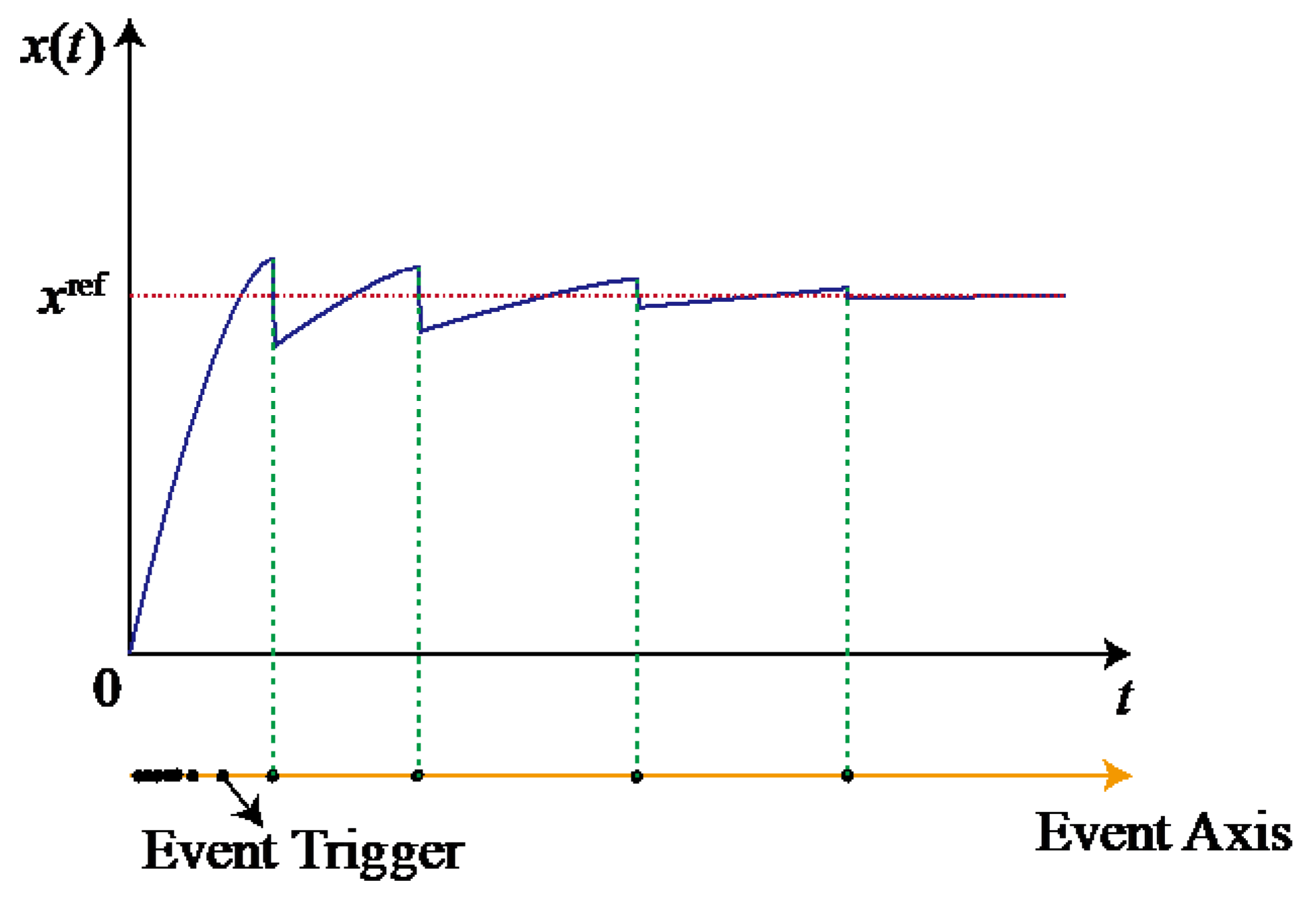
The event-triggered mechanism is similar to the idea of variable structure control [91]. The system control state updates and broadcasts its state when the system reaches a certain threshold away from the stable equilibrium point. The controller remains silent when the system is within the state threshold or the state reaches the convergence phase plane, at which point the system will spontaneously converge to the stable state even if the control state is not updated. Figure 6 shows the regulation pattern of the system with the event-triggered mechanism.
Research on the application of event-triggered mechanisms to improve the consensus algorithm in order to optimize the frequency and voltage regulation process of multi-parallel inverter microgrids is presented in [92,93,94,95,96,97,98]. To summarize the existing designs and applications of event-triggered-based consensus algorithms, the following highlights can be mentioned regarding the design of event-triggered mechanisms.

3.2.1. Event-Trigger Function

The term “event” in the event-trigger mechanism refers to the event that the event function fj is greater than 0. This means that when the event-trigger function satisfies fj(t) ≥ 0, the inverters broadcast their latest output signal to the connected inverters connected on the communication network. Further, when the event-trigger function satisfies fj(t) < 0, the individual inverters remain silent, while the consensus algorithm of each inverter uses the last signal sent by the inverter communicating with it. There is a certain pattern to the design of event-trigger functions for event-triggered mechanisms, which are often in the following form:
f j ( t ) = e j ( t ) 2 M ( θ ) z j ( t ) 2
M(θ) is a specific function consisting of various types of coefficients related to communication or network structure parameters. ej(t) is the error function consisting of the actual value of the state variable and the consensus state variable, and zj(t) is the consensus algorithm function. For example, the event-trigger function in [92,96] are both in this form.

3.2.2. Zeno Phenomenon

The Zeno phenomenon refers to infinite triggering times in a short period of time [95]. No Zeno phenomenon is an important criterion for the design of event-triggered mechanisms. In general, the method used to prove that no Zeno phenomenon will occur is to show that there is a lower bound for the event-trigger time from the designed method.

3.2.3. Chattering

Numerical chattering can lead to frequent meaningless event triggers after the consensus algorithm has reached a steady state. Therefore, to further reduce the event-trigger frequency, the absolute or squared value of the error function ej(t) or the consensus algorithm function zj(t) can be used as an indicator to set the corresponding threshold for an anti-chattering design. However, the anti-chattering threshold should not be set too large, or it will affect the stability of the event-triggering consensus algorithm.

3.2.4. Consensus Signal Selection

In [92,93,94,95,96,97,98], the event-triggered consensus algorithm is adopted to design the secondary-frequency and voltage-regulation method, but the consensus signals are selected as the frequency and voltage signals themselves. According to the previous discussion of droop-based control, an important requirement in the design of the secondary-frequency and voltage regulation link based on droop control is that the secondary-frequency and voltage-regulation component of each inverter should be of the same value; otherwise, the droop characteristics will not be maintained. Therefore, in order for the droop characteristics to remain unchanged, the existing event-triggered consensus algorithms for secondary-voltage and frequency regulation adopt additional components to maintain the invariance of the droop relationship among inverters. For example, in [92,95,96], the power differential signal is introduced to compensate for the original consensus algorithm to maintain the droop relationship. In [97], an additional active power droop consensus component uPi is added to the consensus algorithm, and the whole method becomes complicated.
At present, the theory on and analysis of consensus algorithms with event-triggered mechanisms are not yet mature. The impact of the event-triggered mechanism on the small signal and transient stability of microgrid systems has not yet been fully studied.

3.3. Active Disturbance Rejection Control and Robust Control Method

As mentioned before, non-ideal operating conditions such as disturbances, harmonics, and imbalances are common in the operational control of multi-parallel microgrids. Therefore, control methods for frequency and voltage-regulation control under various types of disturbances and uncertainties are widely used. Among them, active disturbance rejection control (ADRC) and robust control are effective control methods for various types of disturbances and uncertainties [99].

3.3.1. Active Disturbance Rejection Control

ADRC is fundamentally different from robust control. ADRC emphasizes the observation of and compensation for these perturbations, and the control design procedure concentrates on the design of the perturbation observer. Robust control emphasizes the minimization of the effect of model uncertainty on the stability of the system by designing a stabilizing controller. Therefore, the design procedure concentrates on optimizing a specific robust stability criterion. In addition, the source of perturbation that is the focus of concentration by ADRC is generally external perturbation, whereas the robust control is generally targeted at model uncertainty.
The key design procedure is to design the extended state observer (ESO). (17) is known as the extended state observer (ESO). β1 and β2 are known as the observer gains.
{ e 1 = z 1 y z ˙ 1 = z 2 β 1 e 1 + b u z ˙ 2 = β 2 e 1
The advantage of the ADRC control method is its ability to effectively suppress external disturbances, enabling the system to recover to the steady-state equilibrium more quickly after being disturbed. The ADRC control method has been applied in some research to design control methods for microgrid multi-parallel inverter systems with enhanced system immunity [100,101]. Ref. [100] used the ADRC control method to enhance the dynamic immunity of a frequency/voltage secondary regulation scheme based on a consistency algorithm. In [101], the ADRC method is used to enhance the dynamic performance of microgrid inverters.

3.3.2. Robust Control

The key to design a robust controller is to model the uncertainty of the system. System uncertainty can be divided into additive uncertainty and multiplicative uncertainty. Define z as the uncertainty model output and w as the uncertainty model input. According to the transformation between the state space and the transfer function, the matrix of the transfer function from w to z can be obtained as follows:
( x ˙ z y ) = ( A B 1 B 2 C 1 D 11 D 12 C 2 D 21 D 22 ) ( x w u ) , u = K y H z w ( s ) = G 11 + G 12 K ( I G 22 K ) 1 G 21 G i j ( s ) = C i ( s I A ) 1 B j + D i j
The H control optimality problem can then be formulated as finding the control gain matrix K such that the H norm of the transfer function Hzw(s) is minimized:
min K H z w ( s )
Furthermore, the H control suboptimal problem is formulated as finding a control gain matrix K that satisfies the condition that the H norm of Hzw(s) is smaller than the given constant γ:
H z w ( s ) < γ
The basic principle of H control in robust control is presented above. A detailed frequency domain H controller design flow is given in [102] for a typical photovoltaic DCDC converter. Summarizing the design in [102], the design of the frequency domain H controller is concluded in the following flow.
(a) Transform the uncertainty terms in the control model into additive uncertainty form or multiplicative uncertainty form.
(b) Extract and separate the uncertainty terms by linear fractional transformation (LFT). Then, select the suitable weight function W and integrate it into the model G, resulting in a nominal model/uncertainty term/control matrix corresponding to the G-Δ-K form.
(c) The H optimal or sub-optimal problem is solved by μ synthesis algorithm to obtain the required control gain matrix K.
There have been some studies and applications of H control for the problem of the secondary regulation of frequency and voltage in a non-ideal microgrid [103,104,105,106,107]. In [103], the full flow of the design and stability analysis of the H controller for grid-connected inverters is presented. The H problem is solved by the μ synthesis algorithm. In [104], an inner-loop sliding-mode control and an outer-loop hybrid H2/H control was adopted to design a grid-connected inverter with strong robustness, and the linear matrix inequality (LMI) algorithm was used to solve the H problem. In [105], an H controller is applied to a frequency quadratic regulation control loop. The H problem is solved by the μ synthesis algorithm. In [106], the H controller was used to design the control inner loop of a microgrid inverter for islanded operation, and the LMI algorithm was used to solve the H problem. In [107], H controllers are designed for improving the small-signal stability of microgrid inverters against communication delays and non-linear load conditions.
For the application of robust H control methods in the field of frequency/voltage secondary regulation of microgrid inverters, the number of applications and the amount of research are still relatively small, and a unified scheme has not yet been developed. More in-depth and standardized work is desired in the future.

4. Application Case and Future Trends

4.1. Application Case

This section studies an application case for the design and simulation of the secondary-frequency regulation of a stand-alone microgrid with five buses and four inverters based on the consensus algorithm and event-triggered mechanism for islanded operation is presented. Figure 7 shows the structure of the simulation system. The P-δ and Q-U droop is selected as the lower layer control strategy in the control system of inverters. The inner loop of the lower layer is a voltage and current double-loop controller. The inverters are initially operated in grid-connected mode. Then, the system is switched to islanded mode at 1s, after which loads [PL3, QL3] and [PL4, QL4] are put into the system at 6 s and 12 s, respectively. The simulation runs for a total of 18 s. The relevant parameters of the simulated system are given in Table 3, Table 4 and Table 5.
The droop-control loop adopts the droop scheme that considers the secondary-frequency regulation component, as shown in (2). The secondary frequency regulation scheme is used based on a frequency compensation signal consensus algorithm rather than the frequency signal consensus algorithm. The frequency regulation scheme is as follows:
Δ ω ˙ j ( t ) = k ω k = 1 N a j k [ Δ ω k ( t ) Δ ω j ( t ) ] + k ω b j [ ω ref ω j ( t ) ]
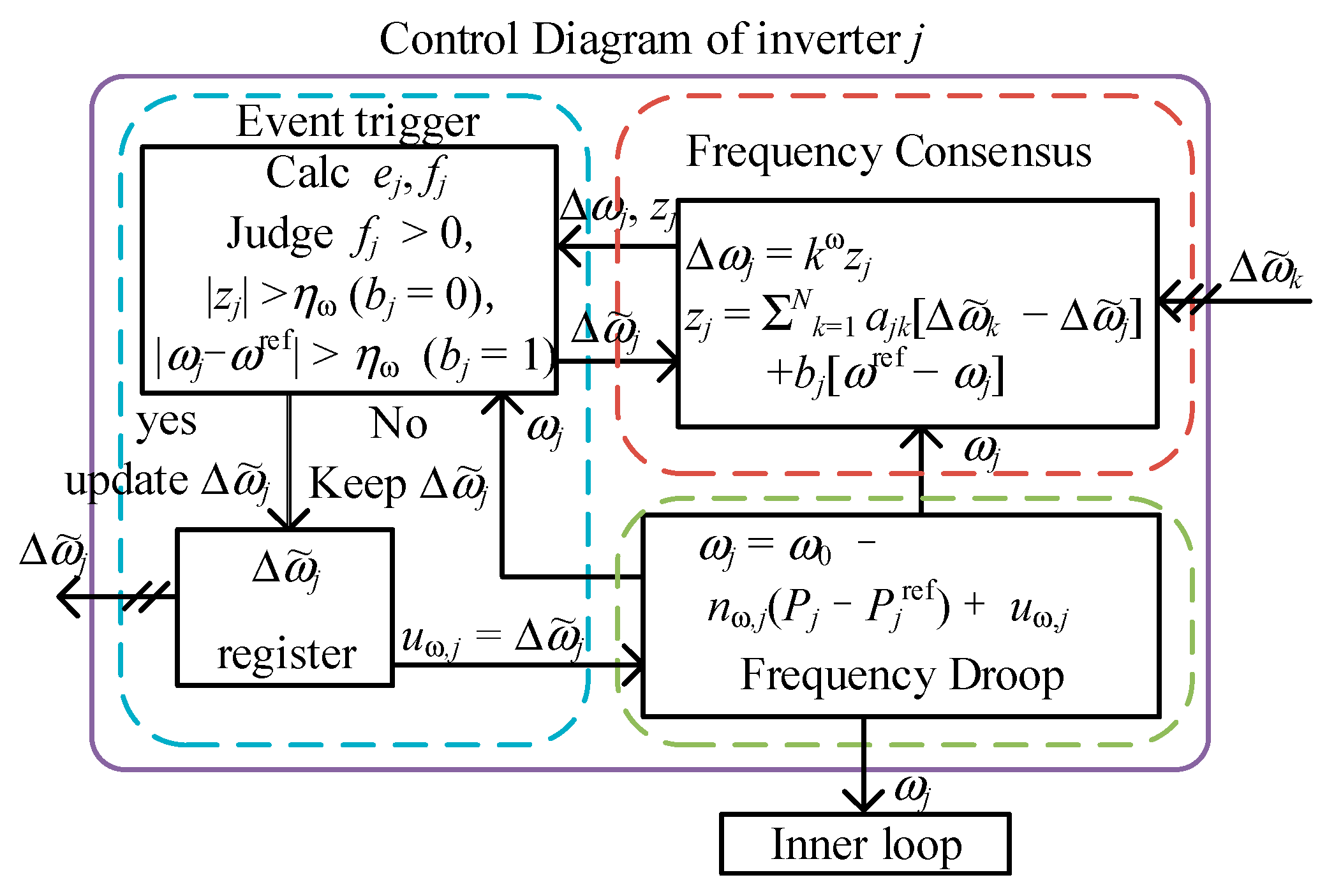
kω is the control gain, which is used to regulate the dynamic time. The event-triggered mechanism is designed as follows. Setting the previous trigger moment as tψj−1 and the next trigger moment as tψj, the new control target variable is defined as follows:
Δ ω ˜ j ( t ) = Δ ω j ( t ψ ) , t [ t ψ , t ψ + 1 ) , ψ = 1 , 2 ,
Then, the trigger conditions for the next trigger moment tψj are as follows:
t ψ j = inf { t | t > t ψ 1 j , f j ( t ) 0 , | z j | η } z j ( t ) = k = 1 N a j k [ Δ ω ˜ k ( t ) Δ ω ˜ j ( t ) ] + b j [ ω ref ω j ( t ) ] e j ( t ) = Δ ω ˜ j ( t ) Δ ω j ( t ) f j ( t ) = e j 2 ( t ) σ j 4 p j 2 z j 2 ( t )
η is the gate value for anti-chattering. zj is the consensus algorithm function. ej is the frequency regulation component error function. fj is the event function. σj is the event-triggered determination coefficient whose range is 0 < σj < 1. pj is the parameter associated with the communication network, which is defined as 2|Nj| + bj = 2pj. |Nj| indicates the number of inverters communicating with the j-th inverter. Figure 8 shows the control block diagram of the scheme.
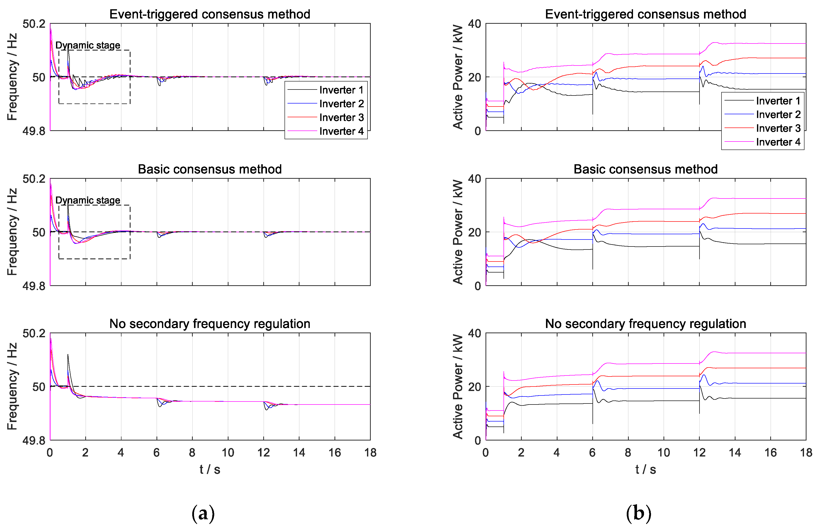
In Figure 9, the frequency dynamic response and output power dynamic response of each inverter with the event-triggered consensus algorithm scheme are presented. The result from the basic consensus algorithm scheme and without secondary frequency regulation are also presented as a comparison. According to Figure 9a, the consensus algorithm with the event-triggered mechanism will have a local abrupt change in regulation dynamics due to the frequent triggering phenomenon compared to the basic consensus algorithm regulation dynamics. However, in terms of overall regulation time, the event-triggered consensus algorithm is relatively similar to the basic consensus algorithm. In contrast, the microgrid system frequency deviates when the secondary frequency regulation loop is not applied. Furthermore, according to Figure 9b, the consensus algorithm with the event-triggered mechanism is more similar to the basic consensus algorithm in terms of power regulation dynamics. Neither method destroys the original droop relationship among the inverters, so it can be shown that the designed secondary frequency regulation scheme is effective.
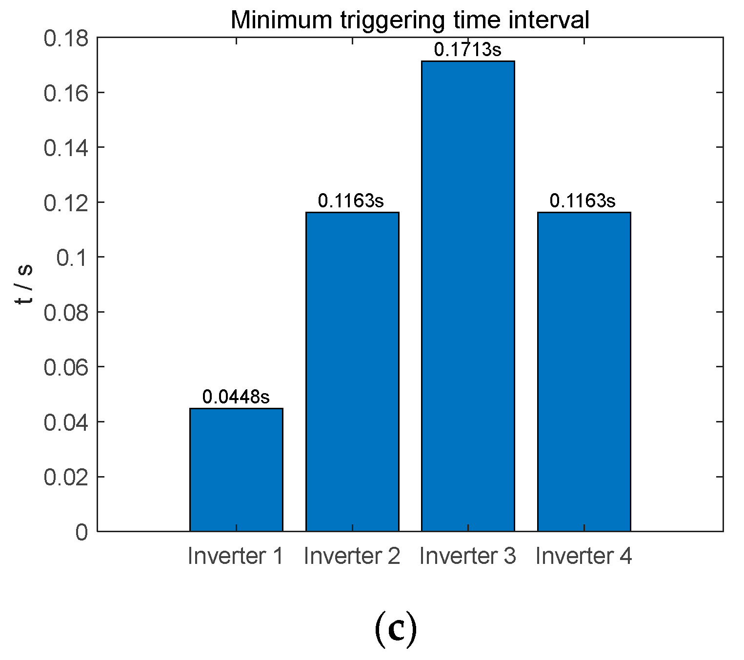
The performance statistics of the consensus algorithm with event-triggered mechanism are presented in Figure 10. According to Figure 10a, it can be seen that the event-triggered mechanism is only triggered frequently during the initial regulation period. As the system approach the steady state, there is little communication among the inverters. According to Figure 10b, it can be seen that the consensus algorithm with the event-triggered mechanism is able to reduce the communication pressure among inverters over 99%, with only inverter 1 updating and broadcasting its own state on an average of 52.9 times in 18 s. In addition, according to Figure 10c, the shortest event-triggered time for inverter 1 is 44.8 ms, and most communication methods are able to meet the communication requirements at this frequency.
Combining the results in Figure 9 and Figure 10, it can be seen that the consensus algorithm with the event-triggered mechanism has a greater advantage over the basic consensus algorithm and is more suitable for a secondary frequency regulation method for a multi-inverter microgrid system.

4.2. Future Trends

For future research and development in secondary-frequency regulation and voltage control techniques, the trends are as follows.
(a) In the secondary-frequency and voltage-regulation problem, distributed schemes, as well as the accomplishment of low communication and a large scale of inverters are going to be the future trends. Correspondingly, the consensus algorithm and event-triggered mechanism as well as multi-parallel inverters’ stability with these methods should gain more focus.
(b) In power balancing and the Q-U droop restoration problem, virtual impedance is now the most common solution. Dynamic and self-adaptive virtual impedance techniques are the potential solutions for this problem. Further, offline or online machine learning techniques might be implemented to improve the dynamic and self-adaptive virtual impedance technique.
(c) In the secondary-frequency and voltage regulation control under non-ideal (including disturbances, harmonic waves, and non-linear loads as well as grid unbalance) conditions, the H control method is powerful and promising. However, the design of H controllers is still not standardized. The design procedure is still of great complexity and cannot be applied to an inverter in an arbitrary situation. This should be a future research focus.

5. Conclusions

Starting from the basic control methods of multi-parallel inverter microgrid systems, this paper analyses the problem of the centralized, decentralized, and distributed secondary regulation of frequency and voltage in multiple inverter microgrid systems. The advantages, disadvantages, and application scenarios of each method are analyzed. Then, the paper systematically describes the origin of the power-balancing problem and the ideas for solving this problem. The research progress on the power-balancing problem is listed and summarized. In addition, the problems encountered in the control of frequency and voltage regulation of multiple parallel inverter microgrids with disturbances, harmonics, and unbalanced operating conditions are analyzed. The research progress proposed in existing research is listed and reviewed.
For solving the key problems in the secondary-frequency and voltage-regulation control of a multiple-inverter microgrid, the common key techniques, such as the virtual impedance technique, consensus algorithms, and event-triggered mechanisms, as well as ADRC and robust control methods, are analyzed and reviewed. The virtual impedance technique is effective in the power-balancing problem and small-signal stability enhancement of multi-parallel inverters. The consensus algorithm with the event-triggered mechanism is an important method to achieve low-communication distributed secondary-frequency voltage regulation. Some key issues in the design of consensus algorithms with event-triggered mechanisms are summarized in the following. ADRC and robust control are commonly used to solve the operational control problems of multiple parallel inverter microgrids with disturbances, harmonics, and unbalanced operating conditions.
Finally, a typical microgrid system with five buses and four inverters is used as an application case to verify the effect of the consensus algorithm with event-triggered mechanism for secondary-frequency regulation control. According to the simulation results, the designed control scheme can reduce the communication pressure among inverters by more than 99%. The shortest communication time between inverters is 44.8 ms, which enables the consensus algorithm to be applied to all kinds of conventional or advanced communication networks. At the same time, the regulation dynamics of the consensus algorithm and the original droop relationship remain invariant according to the simulation result.

Author Contributions

Writing—review and editing, J.D. Review, C.G. Funding acquisition, J.B. Funding acquisition, L.Z. Funding acquisition, Y.H. Supervision and project administration, Z.W. All authors have read and agreed to the published version of the manuscript.

Funding

This research is funded by the National Key R&D Program Funding Projects (2018YFB1503000, 2018YFB1503001), the Fund of Shanghai Science and Technology Development (21DZ1207300) and the fund of Industrial Strengthening Program Projects from the Shanghai Municipal Commission of Economy and Informatization (2021).

Conflicts of Interest

The authors declare no conflict of interest. The funders had no role in the design of the study; in the collection, analyses, or interpretation of data; in the writing of the manuscript; or in the decision to publish the results.

Appendix A. A Brief Proof of the Stability of the Consensus Algorithm

A brief proof of the stability of the consensus algorithm is presented. The basic form of the consensus algorithm in continuous form is as follows:
x ˙ i = u i u i = j = 1 M a i j ( x j x i )
Define the Lyapunov function as follows:
V ( x , t ) = x T x
Its time derivative is as follows:
V ˙ = 2 x T x ˙ = 2 i = 1 N x i u i = 2 i = 1 N x i j = 1 N [ a i j ( x j x i ) ]
where
j = 1 N a i j ( x j x i ) = j = 1 N a i j x j x i j = 1 N a i j = j = 1 N a i j x j d i x i
Substituting (A3) into (A1) and organizing it into compact form results in the following:
V ˙ = 2 i = 1 N x i ( j = 1 N a i j x j d i x i ) = 2 x T L x
According to the Lyapunov direct method, the system of (A1) is stable.

References

  1. Badal, F.R.; Das, P.; Sarker, S.K.; Das, S.K. A survey on control issues in renewable energy integration and microgrid. Prot. Control Mod. Power Syst. 2019, 4, 8. [Google Scholar] [CrossRef] [Green Version]
  2. Solanki, B.V.; Canizares, C.A.; Bhattacharya, K. Practical Energy Management Systems for Isolated Microgrids. IEEE Trans. Smart Grid 2018, 10, 4762–4775. [Google Scholar] [CrossRef]
  3. Palizban, O.; Kauhaniemi, K. Hierarchical control structure in microgrids with distributed generation: Island and grid-connected mode. Renew. Sustain. Energy Rev. 2015, 44, 797–813. [Google Scholar] [CrossRef]
  4. Wang, Y.; Nguyen, T.-L.; Xu, Y.; Tran, Q.-T.; Caire, R. Peer-to-Peer Control for Networked Microgrids: Multi-Layer and Multi-Agent Architecture Design. IEEE Trans. Smart Grid 2020, 11, 4688–4699. [Google Scholar] [CrossRef]
  5. Song, Y.; Hill, D.J.; Liu, T. Impact of DG Connection Topology on the Stability of Inverter-Based Microgrids. IEEE Trans. Power Syst. 2019, 34, 3970–3972. [Google Scholar] [CrossRef]
  6. Guo, X.; Chen, W. Control of multiple power inverters for more electronics power systems: A review. CES Trans. Electr. Mach. Syst. 2018, 2, 255–263. [Google Scholar] [CrossRef]
  7. Lasseter, R.H.; Chen, Z.; Pattabiraman, D. Grid-Forming Inverters: A Critical Asset for the Power Grid. IEEE J. Emerg. Sel. Top. Power Electron. 2019, 8, 925–935. [Google Scholar] [CrossRef]
  8. Chen, B.; Wang, J.; Lu, X.; Chen, C.; Zhao, S. Networked Microgrids for Grid Resilience, Robustness, and Efficiency: A Review. IEEE Trans. Smart Grid 2020, 12, 18–32. [Google Scholar] [CrossRef]
  9. Neves, R.V.A.; Machado, R.Q.; Oliveira, V.A.; Wang, X.; Blaabjerg, F. Multitask Fuzzy Secondary Controller for AC Microgrid Operating in Stand-Alone and Grid-Tied Mode. IEEE Trans. Smart Grid 2018, 10, 5640–5649. [Google Scholar] [CrossRef]
  10. Cao, W.; Ma, Y.; Yang, L.; Wang, F.; Tolbert, L.M. D–Q Impedance Based Stability Analysis and Parameter Design of Three-Phase Inverter-Based AC Power Systems. IEEE Trans. Ind. Electron. 2017, 64, 6017–6028. [Google Scholar] [CrossRef]
  11. Rocabert, J.; Luna, A.; Blaabjerg, F.; Rodríguez, P. Control of Power Converters in AC Microgrids. IEEE Trans. Power Electron. 2012, 27, 4734–4749. [Google Scholar] [CrossRef]
  12. Chen, J.; Milano, F.; Donnell, T.O. Assessment of Grid-Feeding Converter Voltage Stability. IEEE Trans. Power Syst. 2019, 34, 3980–3982. [Google Scholar] [CrossRef]
  13. Dissanayake, A.M.; Ekneligoda, N.C. Decentralized Optimal Stabilization of Active Loads in Islanded Microgrids. IEEE Trans. Smart Grid 2020, 12, 932–942. [Google Scholar] [CrossRef]
  14. Alghamdi, B.; Canizares, C.A. Frequency Regulation in Isolated Microgrids Through Optimal Droop Gain and Voltage Control. IEEE Trans. Smart Grid 2020, 12, 988–998. [Google Scholar] [CrossRef]
  15. Zhao-Xia, X.; Mingke, Z.; Yu, H.; Guerrero, J.M.; Vasquez, J.C. Coordinated Primary and Secondary Frequency Support Between Microgrid and Weak Grid. IEEE Trans. Sustain. Energy 2018, 10, 1718–1730. [Google Scholar] [CrossRef] [Green Version]
  16. Tayab, U.B.; Bin Roslan, M.A.; Hwai, L.J.; Kashif, M. A review of droop control techniques for microgrid. Renew. Sustain. Energy Rev. 2017, 76, 717–727. [Google Scholar] [CrossRef]
  17. Vijay, A.S.; Dheer, D.K.; Tiwari, A.; Doolla, S. Performance Evaluation of Homogeneous and Heterogeneous Droop-Based Systems in Microgrid—Stability and Transient Response Perspective. IEEE Trans. Energy Convers. 2018, 34, 36–46. [Google Scholar] [CrossRef]
  18. Du, W.; Chen, Z.; Schneider, K.P.; Lasseter, R.H.; Nandanoori, S.P.; Tuffner, F.K.; Kundu, S. A Comparative Study of Two Widely Used Grid-Forming Droop Controls on Microgrid Small-Signal Stability. IEEE J. Emerg. Sel. Top. Power Electron. 2019, 8, 963–975. [Google Scholar] [CrossRef]
  19. Andishgar, M.H.; Gholipour, E.; Hooshmand, R.A. An overview of control approaches of inverter-based microgrids in is-landing mode of operation. Renew. Sustain. Energy Rev. 2017, 80, 1043–1060. [Google Scholar] [CrossRef]
  20. Wang, S.; Liu, Z.; Liu, J.; Boroyevich, D.; Burgos, R. Small-Signal Modeling and Stability Prediction of Parallel Droop-Controlled Inverters Based on Terminal Characteristics of Individual Inverters. IEEE Trans. Power Electron. 2019, 35, 1045–1063. [Google Scholar] [CrossRef]
  21. Hu, J.; Shan, Y.; Guerrero, J.M.; Ioinovici, A.; Chan, K.W.; Rodriguez, J. Model predictive control of microgrids—An overview. Renew. Sustain. Energy Rev. 2020, 136, 110422. [Google Scholar] [CrossRef]
  22. Babayomi, O.; Li, Z.; Zhang, Z. Distributed Secondary Frequency and Voltage Control of Parallel-Connected VSCs in Microgrids: A Predictive VSG-Based Solution. CPSS Trans. Power Electron. Appl. 2020, 5, 342–351. [Google Scholar] [CrossRef]
  23. Du, W.; Lasseter, R.; Khalsa, A. Survivability of Autonomous Microgrid during Overload Events. In Proceedings of the 2020 IEEE Power & Energy Society General Meeting (PESGM), Montreal, QC, Canada, 2–6 August 2020; p. 1. [Google Scholar] [CrossRef]
  24. Wang, X.; Blaabjerg, F. Harmonic stability in power electronic-based power systems: Concept, modeling, and analysis. IEEE Trans. Smart Grid 2019, 10, 2858–2870. [Google Scholar] [CrossRef] [Green Version]
  25. Mahmood, H.; Jiang, J. Decentralized Power Management of Multiple PV, Battery, and Droop Units in an Islanded Microgrid. IEEE Trans. Smart Grid 2019, 2, 1898–1906. [Google Scholar] [CrossRef]
  26. Lu, D.; Wang, X.; Blaabjerg, F. Impedance-based analysis of dc link voltage dynamics in voltage-source converters. IEEE Trans. Power Electron. 2019, 34, 3973–3985. [Google Scholar] [CrossRef] [Green Version]
  27. Duan, J.; Wang, C.; Xu, H.; Liu, W.; Xue, Y.; Peng, J.-C.; Jiang, H. Distributed Control of Inverter-Interfaced Microgrids Based on Consensus Algorithm with Improved Transient Performance. IEEE Trans. Smart Grid. 2017, 10, 1303–1312. [Google Scholar] [CrossRef]
  28. Golsorkhi, M.S.; Lu, D.D.-C.; Guerrero, J. A GPS-Based Decentralized Control Method for Islanded Microgrids. IEEE Trans. Power Electron. 2016, 32, 1615–1625. [Google Scholar] [CrossRef] [Green Version]
  29. Watson, J.; Lestas, I. Frequency and Voltage Regulation in Hybrid AC/DC Networks. IEEE Trans. Control. Syst. Technol. 2020, 29, 1839–1849. [Google Scholar] [CrossRef]
  30. Simpson-Porco, J.; Shafiee, Q.; Dorfler, F.; Vasquez, J.; Guerrero, J.M.; Bullo, F. Secondary Frequency and Voltage Control of Islanded Microgrids via Distributed Averaging. IEEE Trans. Ind. Electron. 2015, 62, 7025–7038. [Google Scholar] [CrossRef]
  31. Hu, J.; Lanzon, A. Distributed Finite-Time Consensus Control for Heterogeneous Battery Energy Storage Systems in Droop-Controlled Microgrids. IEEE Trans. Smart Grid 2019, 5, 4751–4761. [Google Scholar] [CrossRef] [Green Version]
  32. Delghavi, M.B.; Yazdani, A. Sliding-Mode Control of AC Voltages and Currents of Dispatchable Distributed Energy Resources in Master-Slave-Organized Inverter-Based Microgrids. IEEE Trans. Smart Grid 2017, 10, 980–991. [Google Scholar] [CrossRef]
  33. Mortezaei, A.; Simoes, M.; Savaghebi, M.; Guerrero, J.; Al-Durra, A. Cooperative control of multi-master-slave islanded microgrid with power quality enhancement based on conservative power theory. IEEE Trans. Smart Grid 2018, 4, 2964–2975. [Google Scholar] [CrossRef] [Green Version]
  34. Lasheen, A.; Ammar, M.E.; Zeineldin, H.H.; Al-Durra, A.; Shaaban, M.F.; El-Saadany, E. Assessing the Impact of Reactive Power Droop on Inverter Based Microgrid Stability. IEEE Trans. Energy Convers. 2021, 36, 2380–2392. [Google Scholar] [CrossRef]
  35. Lou, G.; Gu, W.; Xu, Y.; Cheng, M.; Liu, W. Distributed MPC Based Secondary Voltage Control Scheme for Autonomous Droop Controlled Microgrids. IEEE Trans. Sustain. Energy 2017, 8, 792–804. [Google Scholar] [CrossRef]
  36. Dong, J.; Gong, C.; Chen, H.; Wang, Z. Secondary frequency regulation and stabilization method of islanded droop inverters based on integral leading compensator. Energy Rep. 2022, 8, 1718–1730. [Google Scholar] [CrossRef]
  37. Olfati-Saber, R.; Fax, J.A.; Murray, R.M. Consensus and Cooperation in Networked Multi-Agent Systems. Proc. IEEE 2007, 95, 215–233. [Google Scholar] [CrossRef] [Green Version]
  38. Chen, G.; Guo, Z. Distributed Secondary and Optimal Active Power Sharing Control for Islanded Microgrids with Commu-nication Delays. IEEE Trans. Smart Grid 2019, 2, 2002–2014. [Google Scholar] [CrossRef]
  39. Yan, Y.; Shi, D.; Bian, D.; Huang, B.; Yi, Z.; Wang, Z. Small-Signal Stability Analysis and Performance Evaluation of Microgrids Under Distributed Control. IEEE Trans. Smart Grid 2018, 10, 4848–4858. [Google Scholar] [CrossRef] [Green Version]
  40. Wang, R.; Li, W.; Sun, Q.; Li, Y.; Gui, Y.; Wang, P. Event-triggered improved consensus algorithm distributed secondary frequency regulation of multi-inverter microgrid systems with islanded operation. In Proceedings of the CSEE, Lisbon, Portugal, 10–12 April 2022. [Google Scholar]
  41. Xia, Y.; Xu, Y.; Wang, Y.; Mondal, S.; Dasgupta, S.; Gupta, A.K.; Gupta, G.M. A Safe Policy Learning-Based Method for Decentralized and Economic Frequency Control in Isolated Networked-Microgrid Systems. IEEE Trans. Sustain. Energy 2022, 13, 1982–1993. [Google Scholar] [CrossRef]
  42. Feng, K.; Liu, C. Distributed Hierarchical Control for Fast Frequency Restoration in VSG-Controlled Islanded Microgrids. IEEE Open J. Ind. Electron. Soc. 2022, 3, 496–506. [Google Scholar] [CrossRef]
  43. Khayat, Y.; Shafiee, Q.; Heydari, R.; Naderi, M.; Dragicevic, T.; Simpson-Porco, J.W.; Dorfler, F.; Fathi, M.; Blaabjerg, F.; Guerrero, J.M.; et al. On the Secondary Control Architectures of AC Microgrids: An Overview. IEEE Trans. Power Electron. 2020, 35, 6482–6500. [Google Scholar] [CrossRef]
  44. Rashidi, R.; Hatami, A.; Abedini, M. Multi-microgrid energy management through tertiary-level control: Structure and case study. Sustain. Energy Technol. Assess. 2021, 47, 101395. [Google Scholar] [CrossRef]
  45. Ramirez, D.A.; Garces, A.; Mora-Florez, J.J. A Convex Approximation for the Tertiary Control of Unbalanced Microgrids. Electr. Power Syst. Res. 2021, 199, 107423. [Google Scholar] [CrossRef]
  46. Mohammed, A.; Refaat, S.S.; Bayhan, S.; Abu-Rub, H. AC Microgrid Control and Management Strategies: Evaluation and Review. IEEE Power Electron. Mag. 2019, 6, 18–31. [Google Scholar] [CrossRef]
  47. Muhtadi, A.; Pandit, D.; Nguyen, N.; Mitra, J. Distributed Energy Resources Based Microgrid: Review of Architecture, Control, and Reliability. IEEE Trans. Ind. Appl. 2021, 57, 2223–2235. [Google Scholar] [CrossRef]
  48. Sun, H.; Guo, Q.; Qi, J.; Ajjarapu, V.; Bravo, R.; Chow, J.; Li, Z.; Moghe, R.; Nasr-Azadani, E.; Tamrakar, U.; et al. Review of Challenges and Research Opportunities for Voltage Control in Smart Grids. IEEE Trans. Power Syst. 2019, 34, 2790–2801. [Google Scholar] [CrossRef] [Green Version]
  49. Bialas, H.; Pawelek, R.; Wasiak, I. A Simulation Model for Providing Analysis of Wind Farms Frequency and Voltage Regulation Services in an Electrical Power System. Energies 2021, 14, 2250. [Google Scholar] [CrossRef]
  50. Razi, R.; Iman-Eini, H.; Hamzeh, M. An Impedance-Power Droop Method for Accurate Power Sharing in Islanded Resistive Microgrids. IEEE J. Emerg. Sel. Top. Power Electron. 2019, 8, 3763–3771. [Google Scholar] [CrossRef]
  51. Dheer, D.K.; Gupta, Y.; Doolla, S. A Self-Adjusting Droop Control Strategy to Improve Reactive Power Sharing in Islanded Microgrid. IEEE Trans. Sustain. Energy 2019, 11, 1624–1635. [Google Scholar] [CrossRef]
  52. Cao, W.; Ma, Y.; Wang, F.; Tolbert, L.M.; Xue, Y. Low-Frequency Stability Analysis of Inverter-Based Islanded Multiple-Bus AC Microgrids Based on Terminal Characteristics. IEEE Trans. Smart Grid 2020, 11, 3662–3676. [Google Scholar] [CrossRef]
  53. Mobashsher, M.M.; Keypour, R.; Savaghebi, M. Distributed optimal voltage control in islanded microgrids. Int. Transac-Tions Electr. Energy Syst. 2021, 31, 13045. [Google Scholar] [CrossRef]
  54. Sun, L.; Sun, K.; Hou, Y.; Hu, J. Optimized Autonomous Operation Control to Maintain the Frequency, Voltage and Accurate Power Sharing for DGs in Islanded Systems. IEEE Trans. Smart Grid 2020, 5, 3885–3895. [Google Scholar] [CrossRef]
  55. Ge, P.; Zhu, Y.; Green, T.C.; Teng, F. Resilient Secondary Voltage Control of Islanded Microgrids: An ESKBF-Based Distributed Fast Terminal Sliding Mode Control Approach. IEEE Trans. Power Syst. 2020, 36, 1059–1070. [Google Scholar] [CrossRef]
  56. Li, X.; Zhang, H.; Shadmand, M.B.; Balog, R.S. Model Predictive Control of a Voltage-Source Inverter with Seamless Transition Between Islanded and Grid-Connected Operations. IEEE Trans. Ind. Electron. 2017, 64, 7906–7918. [Google Scholar] [CrossRef]
  57. Ramezani, M.; Li, S.; Musavi, F.; Golestan, S. Seamless Transition of Synchronous Inverters Using Synchronizing Virtual Torque and Flux Linkage. IEEE Trans. Ind. Electron. 2019, 67, 319–328. [Google Scholar] [CrossRef]
  58. Lou, G.; Gu, W.; Wang, J.; Gu, B. A Unified Control Scheme Based on a Disturbance Observer for Seamless Transition Operation of Inverter-Interfaced Distributed Generation. IEEE Trans. Smart Grid 2017, 9, 5444–5454. [Google Scholar] [CrossRef]
  59. Ganjian-Aboukheili, M.; Shahabi, M.; Shafiee, Q.; Guerrero, J.M. Seamless Transition of Microgrids Operation From Grid-Connected to Islanded Mode. IEEE Trans. Smart Grid 2019, 11, 2106–2114. [Google Scholar] [CrossRef]
  60. Raeispour, M.; Atrianfar, H.; Baghaee, H.R.; Gharehpetian, G.B. Resilient H∞ Consensus-Based Control of Autonomous AC Microgrids with Uncertain Time-Delayed Communications. IEEE Trans. Smart Grid 2020, 5, 3871–3884. [Google Scholar] [CrossRef]
  61. Zhou, J.; Shi, M.; Chen, Y.; Chen, X.; Wen, J.; He, H. A Novel Secondary Optimal Control for Multiple Battery Energy Storages in a DC Microgrid. IEEE Trans. Smart Grid 2020, 11, 3716–3725. [Google Scholar] [CrossRef]
  62. Lou, G.; Gu, W.; Lu, X.; Xu, Y.; Hong, H. Distributed Secondary Voltage Control in Islanded Microgrids with Consideration of Communi-cation Network and Time Delays. IEEE Trans. Smart Grid 2020, 11, 3702–3715. [Google Scholar] [CrossRef]
  63. Yan, H.; Zhou, X.; Zhang, H.; Yang, F.; Wu, Z.-G. A Novel Sliding Mode Estimation for Microgrid Control with Communication Time Delays. IEEE Trans. Smart Grid 2017, 10, 1509–1520. [Google Scholar] [CrossRef]
  64. Rosero, C.X.; Velasco, M.; Marti, P.; Camacho, A.; Miret, J.; Castilla, M. Analysis of Consensus-Based Islanded Microgrids Subject to Unexpected Electrical and Communication Partitions. IEEE Trans. Smart Grid 2018, 10, 5125–5135. [Google Scholar] [CrossRef] [Green Version]
  65. Ali, R.; O’Donnell, T. Analysis and Mitigation of Harmonic Resonances in Multi–Parallel Grid–Connected Inverters: A Review. Energies 2022, 15, 5438. [Google Scholar] [CrossRef]
  66. Hart, P.J.; Goldman, J.; Lasseter, R.H.; Jahns, T.M. Impact of Harmonics and Unbalance on the Dynamics of Grid-Forming, Fre-quency-Droop-Controlled Inverters. IEEE J. Emerg. Sel. Top. Power Electron. 2020, 2, 976–990. [Google Scholar] [CrossRef]
  67. Acharya, S.; El-Moursi, M.S.; Al-Hinai, A.; Al-Sumaiti, A.S.; Zeineldin, H.H. A Control Strategy for Voltage Unbalance Mitigation in an Islanded Microgrid Considering Demand Side Management Capability. IEEE Trans. Smart Grid 2018, 10, 2558–2568. [Google Scholar] [CrossRef]
  68. Pham, M.-D.; Lee, H.-H. Effective Coordinated Virtual Impedance Control for Accurate Power Sharing in Islanded Mi-crogrid. IEEE Trans. Ind. Electron. 2021, 68, 2279–2288. [Google Scholar] [CrossRef]
  69. Buraimoh, E.; Aluko, A.O.; Oni, O.E.; Davidson, I.E. Decentralized Virtual Impedance- Conventional Droop Control for Power Sharing for Inverter-Based Distributed Energy Resources of a Microgrid. Energies 2022, 15, 4439. [Google Scholar] [CrossRef]
  70. Zhang, M.; Song, B.; Wang, J. Circulating Current Control Strategy Based on Equivalent Feeder for Parallel Inverters in Islanded Microgrid. IEEE Trans. Power Syst. 2018, 34, 595–605. [Google Scholar] [CrossRef]
  71. Zhang, X.; Zhong, Q.-C.; Kadirkamanathan, V.; He, J.; Huang, J. Source-Side Series-Virtual-Impedance Control to Improve the Cascaded System Stability and the Dynamic Performance of Its Source Converter. IEEE Trans. Power Electron. 2018, 34, 5854–5866. [Google Scholar] [CrossRef]
  72. Liang, X.; Andalib-Bin-Karim, C.; Li, W.; Mitolo, M.; Shabbir, M.N.S.K. Adaptive Virtual Impedance-Based Reactive Power Sharing in Virtual Syn-chronous Generator Controlled Microgrids. IEEE Trans. Ind. Appl. 2021, 57, 46–60. [Google Scholar] [CrossRef]
  73. Rodríguez-Cabero, A.; Roldán-Pérez, J.; Prodanovic, M. Virtual Impedance Design Considerations for Virtual Synchronous Machines in Weak Grids. IEEE J. Emerg. Sel. Top. Power Electron. 2020, 8, 1477–1489. [Google Scholar] [CrossRef]
  74. Gurugubelli, V.; Ghosh, A.; Panda, A.K. Parallel inverter control using different conventional control methods and an im-proved virtual oscillator control method in a standalone microgrid. Prot. Control. Mod. Power Syst. 2022, 1, 27. [Google Scholar] [CrossRef]
  75. Deng, W.; Dai, N.; Lao, K.-W.; Guerrero, J.M. A Virtual-Impedance Droop Control for Accurate Active Power Control and Reactive Power Sharing Using Capacitive-Coupling Inverters. IEEE Trans. Ind. Appl. 2020, 56, 6722–6733. [Google Scholar] [CrossRef]
  76. Peng, Z.; Wang, J.; Bi, D.; Wen, Y.; Dai, Y.; Yin, X.; Shen, Z.J. Droop Control Strategy Incorporating Coupling Compensation and Virtual Impedance for Microgrid Application. IEEE Trans. Energy Convers. 2019, 34, 277–291. [Google Scholar] [CrossRef]
  77. Vijay, A.S.; Parth, N.; Doolla, S.; Chandorkar, M.C. An Adaptive Virtual Impedance Control for Improving Power Sharing Among Inverters in Islanded AC Microgrids. IEEE Trans. Smart Grid 2021, 12, 2991–3003. [Google Scholar] [CrossRef]
  78. Qoria, T.; Gruson, F.; Colas, F.; Denis, G.; Prevost, T.; Guillaud, X. Critical Clearing Time Determination and Enhancement of Grid-Forming Converters Embedding Virtual Impedance as Current Limitation Algorithm. IEEE J. Emerg. Sel. Top. Power Electron. 2019, 8, 1050–1061. [Google Scholar] [CrossRef] [Green Version]
  79. Liu, B.; Liu, Z.; Liu, J.; An, R.; Zheng, H.; Shi, Y. An Adaptive Virtual Impedance Control Scheme Based on Small-AC-Signal Injection for Unbalanced and Harmonic Power Sharing in Islanded Microgrids. IEEE Trans. Power Electron. 2019, 34, 12333–12355. [Google Scholar] [CrossRef]
  80. Li, C.; Cao, Y.; Yang, Y.; Xu, J.; Wu, M.; Zhang, W.; Dragičević, T. New Framework of RoCoF-FD for Wideband Stability Evaluation in Renewable Energy Generators with Virtual Impedance Control. IEEE Trans. Smart Grid 2022, 13, 3570–3581. [Google Scholar] [CrossRef]
  81. Wei, B.; Marzàbal, A.; Ruiz, R.; Guerrero, J.M.; Vasquez, J.C. DAVIC: A New Distributed Adaptive Virtual Impedance Control for Parallel-Connected Voltage Source Inverters in Modular UPS System. IEEE Trans. Power Electron. 2019, 34, 5953–5968. [Google Scholar] [CrossRef]
  82. Li, G.; Ma, F.; Luo, A.; He, Z.; Wu, W.; Wei, X.; Zhu, Z.; Guo, J. Virtual impedance-based virtual synchronous generator control for grid-connected inverter under the weak grid situations. IET Power Electron. 2018, 11, 2125–2132. [Google Scholar] [CrossRef]
  83. An, R.; Liu, Z.; Liu, J. Successive-Approximation-Based Virtual Impedance Tuning Method for Accurate Reactive Power Sharing in Islanded Microgrids. IEEE Trans. Power Electron. 2020, 36, 87–102. [Google Scholar] [CrossRef]
  84. Hu, Y.; Shao, Y.; Yang, R.; Long, X.; Chen, G. A Configurable Virtual Impedance Method for Grid-Connected Virtual Synchronous Generator to Improve the Quality of Output Current. IEEE J. Emerg. Sel. Top. Power Electron. 2019, 8, 2404–2419. [Google Scholar] [CrossRef]
  85. Lyu, Z.; Wei, Q.; Zhang, Y.; Zhao, J.; Manla, E. Adaptive Virtual Impedance Droop Control Based on Consensus Control of Reactive Current. Energies 2018, 11, 1801. [Google Scholar] [CrossRef] [Green Version]
  86. Hoang, T.V.; Lee, H.-H. Virtual Impedance Control Scheme to Compensate for Voltage Harmonics with Accurate Harmonic Power Sharing in Islanded Microgrids. IEEE J. Emerg. Sel. Top. Power Electron. 2020, 9, 1682–1695. [Google Scholar] [CrossRef]
  87. Roldán-Pérez, J.; Rodríguez-Cabero, A.; Prodanović, M. Harmonic Virtual Impedance Design for Parallel-Connected Grid-Tied Synchronverters. IEEE J. Emerg. Sel. Top. Power Electron. 2019, 7, 493–503. [Google Scholar] [CrossRef]
  88. Jin, Z.; Wang, X. A DQ-Frame Asymmetrical Virtual Impedance Control for Enhancing Transient Stability of Grid-Forming Inverters. IEEE Trans. Power Electron. 2022, 37, 4535–4544. [Google Scholar] [CrossRef]
  89. Zhu, Y.; Fan, Q.; Liu, B.; Wang, T. An Enhanced Virtual Impedance Optimization Method for Reactive Power Sharing in Microgrids. IEEE Trans. Power Electron. 2018, 33, 10390–10402. [Google Scholar] [CrossRef]
  90. Zhou, Y.; Zhai, Q.; Wu, L. Optimal Operation of Regional Microgrids With Renewable and Energy Storage: Solution Robustness and Nonanticipativity Against Uncertainties. IEEE Trans. Smart Grid 2022, 13, 4218–4230. [Google Scholar] [CrossRef]
  91. Hung, J.Y.; Gao, W.; Hung, J.C. Variable structure control: A survey. IEEE Trans. Ind. Electron. 1993, 40, 2–22. [Google Scholar] [CrossRef]
  92. Chen, M.; Xiao, X.; Guerrero, J.M. Secondary Restoration Control of Islanded Microgrids with a Decentralized Event-Triggered Strategy. IEEE Trans. Ind. Inform. 2017, 14, 3870–3880. [Google Scholar] [CrossRef] [Green Version]
  93. Meng, W.; Wang, X.; Liu, S. Distributed Load Sharing of an Inverter-Based Microgrid with Reduced Communication. IEEE Trans. Smart Grid 2016, 9, 1354–1364. [Google Scholar] [CrossRef]
  94. Abdolmaleki, B.; Shafiee, Q.; Arefi, M.M.; Dragicevic, T. An Instantaneous Event-Triggered Hz–Watt Control for Microgrids. IEEE Trans. Power Syst. 2019, 34, 3616–3625. [Google Scholar] [CrossRef]
  95. Abdolmaleki, B.; Shafiee, Q.; Seifi, A.R.; Arefi, M.M.; Blaabjerg, F. A Zeno-Free Event-Triggered Secondary Control for AC Microgrids. IEEE Trans. Smart Grid 2020, 3, 1905–1916. [Google Scholar] [CrossRef]
  96. Chen, Y.; Li, C.; Qi, D.; Li, Z.; Wang, Z.; Zhang, J. Distributed Event-Triggered Secondary Control for Islanded Microgrids with Proper Trigger Condition Checking Period. IEEE Trans. Smart Grid 2021, 13, 837–848. [Google Scholar] [CrossRef]
  97. Choi, J.; Habibi, S.I.; Bidram, A. Distributed Finite-Time Event-Triggered Frequency and Voltage Control of AC Microgrids. IEEE Trans. Power Syst. 2021, 37, 1979–1994. [Google Scholar] [CrossRef]
  98. Shi, M.; Chen, X.; Zhou, J.; Chen, Y.; Wen, J. Frequency Restoration and Oscillation Damping of Distributed VSGs in Microgrid with Low Bandwidth Communication. IEEE Trans. Smart Grid 2020, 12, 1011–1021. [Google Scholar] [CrossRef]
  99. Mohammadi, F.; Mohammadi-Ivatloo, B.; Gharehpetian, G.B.; Ali, M.H.; Wei, W.; Erdinc, O.; Shirkhani, M. Robust Control Strategies for Microgrids: A Review. IEEE Syst. J. 2021, 16, 2401–2412. [Google Scholar] [CrossRef]
  100. Li, W.; Zhang, M.; Deng, Y. Consensus-Based Distributed Secondary Frequency Control Method for AC Microgrid Using ADRC Technique. Energies 2022, 15, 3184. [Google Scholar] [CrossRef]
  101. Wang, Y.; Tao, L.; Wang, P.; Ma, X.; Cheng, P.; Zhao, D. Improved Linear ADRC for Hybrid Energy Storage Microgrid Output-side Converter. IEEE Trans. Ind. Electron. 2021, 69, 9111–9120. [Google Scholar] [CrossRef]
  102. Ashtiani, N.A.; Azizi, S.M.; Khajehoddin, S.A. Robust Control Design for High-Power Density PV Converters in Weak Grids. IEEE Trans. Control Syst. Technol. 2018, 27, 2361–2373. [Google Scholar] [CrossRef]
  103. Huang, L.; Xin, H.; Dörfler, F. H∞-Control of Grid-Connected Converters: Design, Objectives and Decentralized Stability Certificates. IEEE Trans. Smart Grid 2020, 11, 3805–3816. [Google Scholar] [CrossRef]
  104. Li, Z.; Zang, C.; Zeng, P.; Yu, H.; Li, S.; Bian, J. Control of a Grid-Forming Inverter Based on Sliding-Mode and Mixed H2/H∞ Control. IEEE Trans. Ind. Electron. 2017, 5, 3862–3872. [Google Scholar] [CrossRef]
  105. Bevrani, H.; Feizi, M.R.; Ataee, S. Robust Frequency Control in an Islanded Microgrid: H∞ and μ-Synthesis Approaches. IEEE Trans. Smart Grid 2016, 7, 706–717. [Google Scholar] [CrossRef] [Green Version]
  106. Armin, M.; Rahman, M.; Rahman, M.M.; Sarker, S.K.; Das, S.K.; Islam, M.R.; Kouzani, A.Z.; Mahmud, M.P. Robust Extended H∞ Control Strategy Using Linear Matrix Inequality Approach for Islanded Microgrid. IEEE Access 2020, 8, 135883–135896. [Google Scholar] [CrossRef]
  107. Baghaee, H.R.; Mirsalim, M.; Gharehpetian, G.B.; Talebi, H.A. A generalized descriptor-system robust H∞ control of autonomous microgrids to improve small and large signal stability considering communication delays and load nonlinearities. Int. J. Electr. Power Energy Syst. 2017, 92, 63–82. [Google Scholar] [CrossRef]
Figure 1. Structure of problems and technologies introduced in the paper.
Energies 15 08533 g001
Figure 2. Control block diagram of the droop-control inverter.
Energies 15 08533 g002
Figure 3. Schematic diagram of the droop curve: (a) P-ω droop curve; (b) Q-U droop curve.
Energies 15 08533 g003
Figure 4. Inverter power transferring model: (a) line diagram of the inverter-PCC connection; (b) corresponding phase diagram.
Energies 15 08533 g004
Figure 5. Schematic diagram of the virtual impedance technique.
Energies 15 08533 g005
Figure 6. Regulation pattern with event-triggered mechanism.
Energies 15 08533 g006
Figure 7. Structure of the simulation system.
Energies 15 08533 g007
Figure 8. Block diagram of the consensus algorithm with event-triggered mechanism for secondary-frequency regulation control.
Energies 15 08533 g008
Figure 9. Frequency dynamics and output power dynamics under different control schemes: (a) frequency response curve; (b) output power response curve.
Energies 15 08533 g009
Figure 10. Control performance of consensus algorithm with event-triggered mechanism: (a) event-trigger graph; (b) average event-trigger times; (c) minimum triggering time interval.
Energies 15 08533 g010aEnergies 15 08533 g010b
Table 1. Secondary-frequency and voltage-regulation control research review. It is worth mentioning that the analytical research does not propose methods, so there will be no cost, complexity, and accuracy analysis.
Research
Category
LiteratureAbstractCostComplexityAccuracy
Centralized[30]Optimal model established and OPF function solving method proposed.HighHighHigh
[31]Realizes the secondary-frequency regulation task by introducing a common frequency reference system. HighLowMedium
[32]Sliding-mode control-based centralized voltage and frequency secondary-regulation method is proposed.MediumMediumLow
[33]Separates the inverters as microgrid clusters and increases the output voltage quality.LowHighLow
[34]Proposes an MPC-based centralized microgrid control method. Also considers the constraints of frequency variation and SOC of the energy storage device. HighHighHigh
Decentralized[35]An LQR-based method is proposed for local frequency and voltage regulation. Large local calculation.HighHighMedium
[36]MPC-based decentralized frequency regulation method.HighHighMedium
[37]Frequency regulation method without communication. Needs additional stabilizer part.LowMediumLow
Distributed[39]Time-delay impact analysis in consensus method.\\\
[40]Small-signal model for consensus algorithm-based microgrid.\\\
[41]Hierarchical control structure with consensus algorithm-based frequency and voltage regulation.HighHighHigh
[42]Event-triggered-based consensus method for secondary-frequency regulation.LowHighHigh
Table 2. Review list of research on virtual impedance technique.
Research CategoryLiteratureAbstractCostComplexityEffects
Method Proposed[37,72]Adaptive virtual impedance method for reactive power sharing based on transient virtual impedance.MediumLowPower sharing
[74]Particle swarm optimization based on virtual impedance design for oscillation damping.HighMediumStability
[77]Virtual impedance method with dq current droop and additional compensator.MediumLowPower sharing and stability
[81]Proposes a distributed adaptive virtual impedance method for stability enhancement. CAN bus communication is implemented.HighHighStability
[83]Successive approximation-based virtual impedance method. The value of Lv and Rv is time dynamic.MediumLowStability
[85]Adaptive virtual impedance method using consensus algorithm.HighHighPower sharing
[88]DQ frame asymmetrical virtual impedance method.MediumMediumHarmonic wave sharing
[89]Online optimization of virtual impedance scheme.HighMediumPower sharing
Novel
Application
[71]Uses source-side virtual impedance method for cascaded system stability enhancement.MediumHighStability
[75]Uses virtual impedance method for capacitive coupling inverters.LowLowStability on special situation
[76]Uses virtual impedance for active and reactive power decoupling.MediumHighPower sharing
[84]Multi-frequency band virtual impedance for better current quality.HighHighHarmonic wave sharing
[86]Virtual impedance method for accurate harmonic power sharing.HighHighHarmonic power sharing
Analysis[70]Virtual impedance technique stability and function of circling current suppression.\\\
[73,82]Parameter design and analysis of virtual impedance method for week grids.\\\
[78]Critical clearing time analysis for inverter-based power system under the impact of virtual impedance.\\\
[79,87]Virtual impedance method and the harmonic stability and unbalanced operation condition analysis.\\\
[80]Rate of change of frequency analysis for inverters with virtual impedance control scheme.\\\
Table 3. Network parameters of microgrid.
SubjectParameterValue
NetworkLg1/mH, Rg10.35, 0.03
Lg2/mH, Rg20.35, 0.03
Lg3/mH, Rg30.35, 0.03
Lg4/mH, Rg40.35, 0.03
Ll1/mH, R110.318, 0.23
Ll2/mH, Rl21.847, 0.35
Ll3/mH, Rl30.318, 0.23
Ll4/mH, Rl40.194, 0.02
Load(PL1 + jQL1)/V·A(45.9 + j22.8) × 103
(PL2 + jQL2)/V·A(36 + j36) × 103
(PL3 + jQL3)/V·A(9.07 + j0) × 103
(PL4 + jQL4)/V·A(9.07 + j0) × 103
Droop
coefficient
nω,1/[(rad/s)/W]12 × 10−6
nω,2/[(rad/s)/W]6 × 10−6
nω,3/[(rad/s)/W]4 × 10−6
nω,4/[(rad/s)/W]3 × 10−6
Table 4. Inverter parameters.
ParameterValue
LCL inverter side inductorL1/mH3
LCL inverter side ESR/Ω0.3
LCL grid side inductor/mH1.8
LCL grid side ESR/Ω0.18
LCL capacitor/μF (Y-Connection)4.7
Three phase rate line voltage/V380
System frequency/Hz50
PWM frequency/kHz10
Proportional gain of current loop10
Proportional gain for voltage loop0.11
Integral gain for voltage loop50
Active reference for droop loop/kW10
Reactive reference for droop loop/kVar0
Time constant of power filter/s0.1592
Table 5. Event-triggered consensus algorithm parameter.
ParameterValue
Consensus gain kω1.0
Judgment coefficientσ10.5
σ20.5
σ30.5
σ40.5
Gate value for anti-chattering η0.002
Event detection cycle/ms0.1
Publisher’s Note: MDPI stays neutral with regard to jurisdictional claims in published maps and institutional affiliations.