Article

Thermal Performance Analysis of Various Heat Sinks Based on Alumina NePCM for Passive Cooling of Electronic Components: An Experimental Study

1
Department of Mechanical Engineering, University of Engineering and Technology, Lahore 39161, Pakistan
2
Department of Mechanical Engineering and Technology, Government College University, Faisalabad 38000, Pakistan
3
Department of Mechanical, Biomedical and Design Engineering, College of Engineering and Physical Sciences, Aston University, Birmingham B4 7ET, UK
4
Industrial Engineering Department, College of Engineering, King Saud University, P.O. Box 800, Riyadh 11421, Saudi Arabia
5
Department of Agricultural Engineering, Bahauddin Zakariya University, Multan 60800, Pakistan
*
Authors to whom correspondence should be addressed.
Energies 2022, 15(22), 8416; https://doi.org/10.3390/en15228416
Submission received: 25 September 2022 / Revised: 30 October 2022 / Accepted: 3 November 2022 / Published: 10 November 2022
(This article belongs to the Special Issue Thermal Power Systems and Alternative Energy)

Abstract

:
In the modern digital world, electronic devices are being widely employed for various applications where thermal performance represents a significant technical challenge due to continued miniaturization, high heat generated in the system, and non-uniform high-temperature causing failure. Phase change materials (PCMs) owing to the immense heat of fusion are primarily considered for thermal management, but their insulating properties hedge their applications in electronics cooling. Nano-enhanced phase change materials (NePCMs) have the ability to improve the thermal conductivity of PCM, decrease system temperature and escalate the operating time of devices. Accordingly, the current study focused on the experimental investigations for the thermal performance of three heat sinks (HS) with different configurations such as a simple heat sink (SHS), a square pin-fins heat sink (SpfHS), and Cu foam integrated heat sink (CufmHS) with various alumina nanoparticles mass concentrations (0.15, 0.20 and 0.25 wt%) incorporated in PCM (RT-54HC) and at heat flux (0.98–2.94 kW/m2). All HSs reduced the base temperature with the insertion of NePCM compared to the empty SHS. The experimental results identified that the thermal performance of CufmHS was found to be superior in reducing base temperature and enhancing working time at two different setpoint temperatures (SPTs). The maximum drop in base temperature was 36.95%, and a 288% maximum working time enhancement was observed for CufmHS. Therefore, NePCMs are highly recommended for the thermal management of the electronic cooling system.

1. Introduction

The thermal performance of microchannel-based electronic devices is more critical than conventional heat exchangers due to their compact size, light weight, and superior cooling performance. These electronic devices are miniaturizing with expanded functionalities due to rapid growth and development in the modern digital world. The heat generation rate has increased with this compactness in electronic components design, resulting in constantly high component temperature [1,2]. Poor thermal load management of electronic gadgets may compromise their performance, damage crucial components, and deteriorate user satisfaction [3]. A study performed by the US Defense Sector reflects that the disaster rate of smart electronic components grows as the temperature rises outside the working environment. Further, the failure rate decreases by 4% with a temperature reduction of 1 °C [4]. Therefore, the heat generated in electronic circuits must be dissipated immediately in the surroundings to gain the maximum efficiency of the device. This will reduce the chances of severe failure and increase the reliability of the electronic product.
The choice of active cooling techniques for thermal management of electronics is considered inefficient because of the large occupied space, liquid circulation pump maintenance, and fan noise issues resulting in high operational cost and leading to failure of devices [5]. However, passive cooling methods using phase change materials (PCMs) in heat pipes or heat sinks are preferred due to high latent heat, no electrical power consumption, and zero emission [6,7]. In this method, a vast amount of potential energy is ingested by PCMs during the melting phase and released to the environment in solidification, resulting in better thermal management of electronics [8]. Currently, organic PCMs have marvelous features of repeated use, small volume expansion, non-corrosivity, nontoxicity, chemical reliability, and high latent heat storage [9,10]. However, the little thermal conduction response issue of PCMs slows down the charging and discharging time of electronics, which is a serious technical challenge [11]. In order to counter this problem, various types of fins [12], metallic foams [13], and nanoparticles (NPs) [14,15,16] are employed as thermal conductivity enhancement techniques as discussed in Figure 1. These techniques are conjugated with PCMs to enhance thermal conductivity and focus excess heat removal from the system.
Several researchers are investigating the thermal management of cooling devices utilizing heat sinks of extended surfaces integrated with PCMs [17], the fins configurations [18], the filled volume of PCM [19], liquefying temperature of the PCM, and the heating rate are all aspects that affect the execution of PCM-based heat sinks for electronic applications.
A paraffin wax-based PCM filled-in aluminum heat sink having 72 pin fins was numerically investigated for the thermal reliability of electronics devices. Compared to the baseline setup, the highest temperature of the appropriate model dropped by 30%. The optimal design took longer to heat the latent heat than the baseline model, which took less time [20]. The experimental study presented the thermal analysis of round pin-finned heat sinks of three diameters, and at varying heat flux for electronic equipment. PCM was used with three-volume fractions of 0.0, 0.5, and 1.0 in each configuration of heat sinks. A 3 mm round pin-finned heat sink showed superior thermal performance at three setpoint temperatures (SPTs) [21].
A few studies have reported that adding NPs to PCMs may enhance the thermal conductivity of PCMs. Different metal oxide NPs were studied to compare thermal conductivity and heat transfer improvements. Metal oxide NPs are preferred over metal NPs due to their low cost, better thermal stability, and consistent performance [22]. A parallel plate-based fin sink incorporated with PCM and nano-silica (SiO2) was under investigation for electronic chipset cooling. A NePCM-based heat sink improved heating time up to 220% [23]. The computational study examined the melting and heat transmission properties of a nanocomposite phase change material (NCPCM) filled-in heat sink for the passive cooling of electronic devices. Cu NPs of various volume fractions were dispersed in PCM (RT–28HC). The outcomes delivered that the heat carrying rate was enriched by increasing NPs concentrations and reducing melting time [24].
Metallic foams of high porosity are under investigation by many researchers as thermal conductivity enhancers because of their extended surface area and high heat transfer rate capabilities [25]. They are available in various pore sizes characterized by pores per inch (PPI). In the commercial market, metal foams are mostly made of nickel, copper, bronze, stainless steel, aluminum, graphite, and their alloys. The thermal achievement of heat sinks conjugated with alcohol/graphite foam as PCMs was studied at varying heat fluxes. Higher alcohol/graphite foam showed a 24% delay in the heating process while achieving the temperature goal of 90 °C [26].
PCM/NePCM-based HSs are widely investigated to provide a better passive cooling medium for electronic devices as shown in Table 1. Many researchers worked on PCM-based heat sink configurations, and a few attempts have been made for NePCM-based simple heat sinks. However, to the researchers’ familiarity, no noteworthy research has been made that took into consideration all the variables, such as unfinned, finned, metallic foam, and alumina NePCM in the heat sink assembly during NePCM melting (charging) and solidification (discharging) phases. The need of faster passive cooling is to conduct more in-depth experimental studies using nano-PCM bases in different heat sink configurations. The present study examines the influence of NPs concentration, heat flux behavior on the base temperature, and enhancement in the device’s operating time at various SPTs. Further, thermal performances of the simple heat sink (SHS), square pin-fins heat sink (SpfHS), and Cu foam integrated heat sink (CufmHS) are analyzed for the cooling of electronic components. NePCM (RT-54HC/Al2O3) of various mass concentrations of NPs (0.15 wt%, 0.20 wt%, and 0.25 wt%) are introduced in heat sinks, and various heat flux densities are applied to observe heat transfer performance and operating time to achieve various setpoint temperature (SPT) during charging and discharging periods. The key motivation of the present study is to elevate the thermal performance of different heat sinks using NePCM as a working medium at various setpoint temperatures and applied heat flux.

2. Materials and Methods

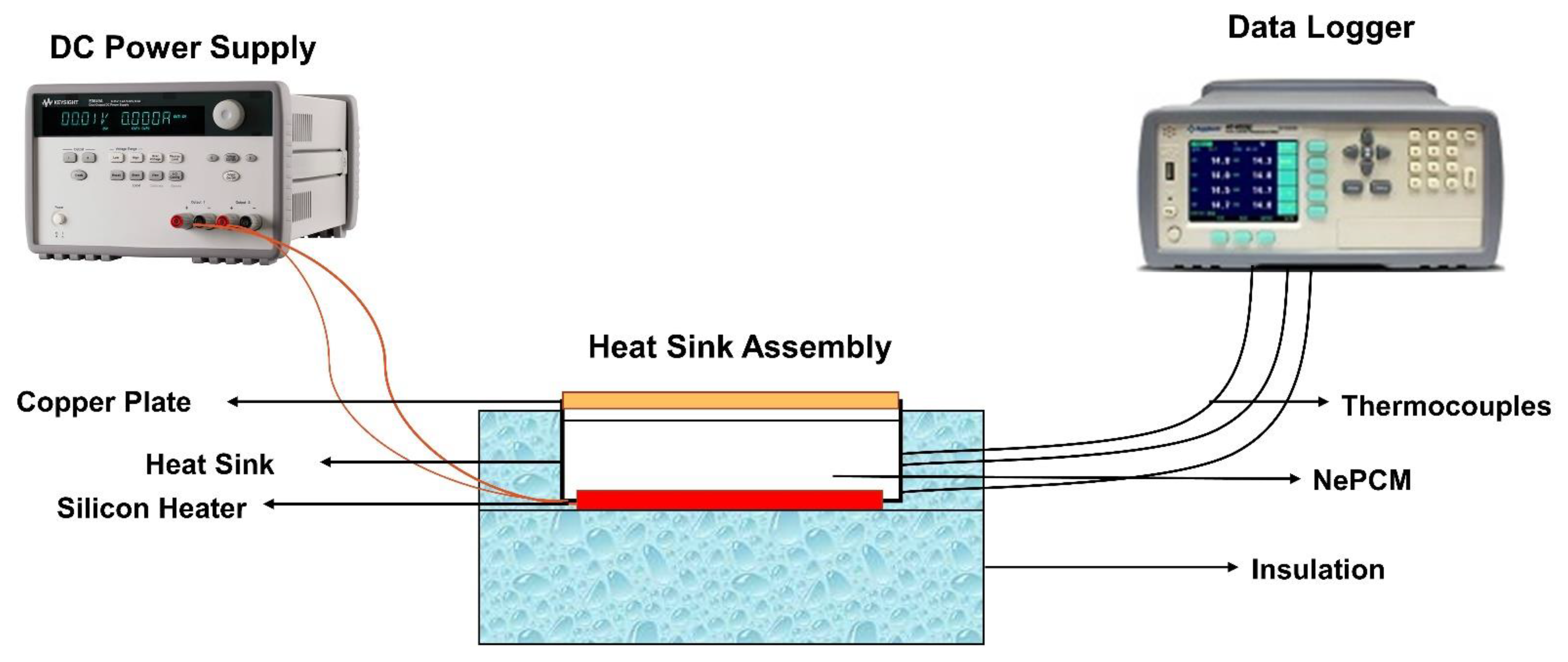
2.1. Experimental Setup

The test setup for the thermal analysis of HS is displayed in Figure 2. The major components of the test setup consisted of DC power supply (Keysight, 6675A, Santa Rosa, CA, USA), thermocouples (OMEGA™, Beijing, China), a silicon heater (OMEGA™, SRFG-610, Beijing, China), a heat sink assembly, a digital data logger (Keysight, 34980A, Santa Rosa, CA, USA), and a laptop. The heat sink assembly had the overall outer dimensions of 116 × 116 × 32 mm3. Different heat sinks having different configurations were individually tested with various heating loads and cooling medium (NePCM). All heat sinks were fabricated using a computerized numerical control (CNC) milling machine. Three input powers of 10 W, 20 W, and 30 W were applied to the heater with the help of a DC power supply to observe the heat generation rate. A data logger was used for measuring thermocouple temperature.

2.2. Heat Sink Assembly and Thermocouple Positioning

In the current research, three heat sinks (SHS, SpfHS, and CufmHS), were used for thermal management. The HS was the primary part of the experimental setup made of aluminum. Aluminum material was chosen instead of copper due to its lightweight, three-times lower density, good thermal conductivity, and corrosion resistance, making it an appropriate choice for thermal inspection [34]. The internal dimension of the heat sink was 101 × 101 × 27 mm3 with an outer side wall thickness of 7.5 mm. A standard 9% volume fraction (γ) as thermal conductivity enhancer of SpfHS was considered by taking a cue from previous research studies and was mathematically calculated using Equation (1).
γ = V T C E V s
γ ” is the percentage of the size covered by fins (VTCE) to the total size occupied by the empty heat sink (Vs). Square pin-fins of 3 × 3 × 27 mm3 were fabricated using a CNC milling machine. Figure 3a presents isometric views of SpfHS. Figure 3b shows a pictorial view of SHS, SpfHS, and CufmHS. All four side walls of the HS were covered with insulation tape of 6 mm thickness to stop heat dissipation. The top side of the HS was covered with a copper plate of 2 mm for unidirectional heat flow for increased heat transfer. A Silicon rubber plate heater of a similar size to the internal HS cavity and of 2 mm thickness was pasted with the thermal grease to the underneath cavity of the HS to sustain uniform heat flux. Thermal grease may help control air gaps, resulting in decreased thermal resistance.
Copper foam (32 PPI, 94% porosity) as a thermal conductivity enhancer was inserted with NePCM in the SHS internal cavity to check thermal performance. Its properties provided by the supplier are discussed in Table 2. It was cleaned with acetone, ethanol, and water before use.
Pre-calibrated and high-precision 11 K-type thermocouples were connected at various spots of the HS to analyze the temperature readings at the charging and discharging time of NePCM at one-minute intervals. Calibration was tested for the temperature series of 15–85 °C with a constant temperature water bath. The thermocouples of 0.25 mm wire diameter were fixed firmly with Araldite epoxy resin to make the joint sealed during the melting phase of NePCM. Two thermocouples labelled B1 and B2 were inserted in the deep grooves at the junction of the top side of the heater and the lower side of the HS. H1 and H2 were mounted at the bottom of the HS to record the temperature. The average of two thermocouples fixed at the parallel position was used for the temperature estimation during performance investigation. In addition, P3–P4, P5–P6, and P7–P8 were fixed inside the walls of HS vertically at height intervals of 8.7 mm. T9 was used to monitor the environment temperature. Table 3 shows the thermocouple positionings.

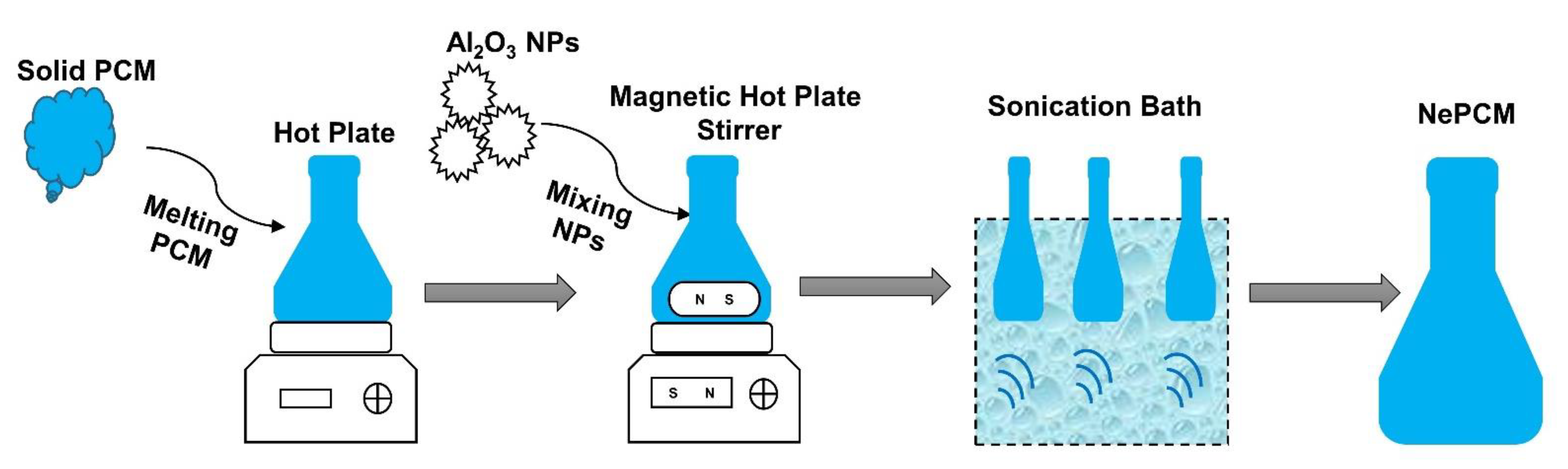
2.3. Preparation of NePCM

One-step and two-step procedures were used for the NePCM preparation [35]. In the one-step method, NPs synthesis and mixing co-occurred. In the two-step method, NPs were acquired in powder shape and mixed in base PCM for uniform dispersion [36]. The two-step procedure was favored due to its low price and its use on a large scale [37]. NePCM was prepared by adding Al2O3 NPs at various mass concentrations (0.15 wt%, 0.20 wt%, and 0.25 wt%) into organic PCM (RT-54HC). The thermophysical dynamics of alumina NPs and PCM are briefed in Table 4. Firstly, a digital analytical balance measured the desired quantity of solid PCM and alumina NPs. Then PCM was liquified at a constant temperature of 65 °C using a hot plate. Alumina NPs were dispersed homogeneously into the liquefied PCM on the magnetic hot plate stirrer for 150 min at 1400 rpm. To obtain uniform dispersion and to avoid the accumulation of NPs, the NePCM mixture was allowed through the ultrasonication process in a sonication bath for 120 min before final use. Finally, the mixture was transferred into the HS cavity and let to solidify at room temperature before thermal analysis. The sequence of steps comprised for the NePCM preparation is discussed in Figure 4.

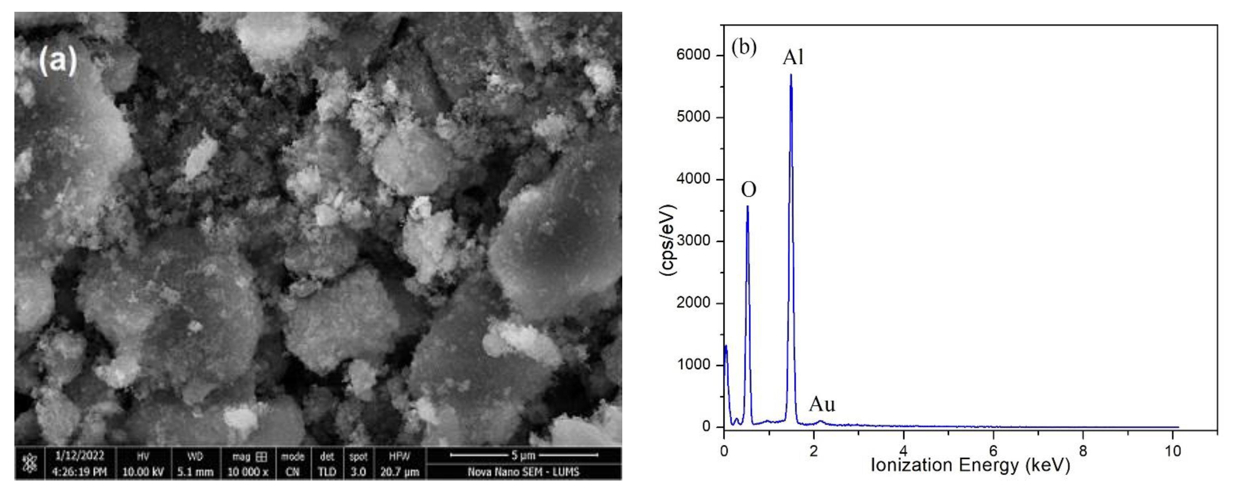
SEM and EDX Analysis of Alumina NPs

SEM and EDX analysis are normally employed to find the morphology and elemental composition of NPs [39]. In this research, alumina NPs were chemically portrayed by means of SEM joined with EDX, as featured in Figure 5a,b. The SEM image exposes aggregation and a slightly larger size of alumina NPs, which may be due to transportation and storage of NPs. The aggregates of NPs were refined during the ultrasonic process of NePCM preparation. The presence of Al and O with the weight percentage of 54.74% and 48.26%, respectively, confirmed the high purity of alumina NPs in EDX analysis as reflected in Figure 5b. NPs were gold coated during EDX analysis to obtain the high quality of peaks.

3. Validation and Uncertainty Estimation of the Test Setup

The heat engendered by the heater was supposed to be hot spell dissipation by the electronic chip, and the HS base was considered the surface of ICs. The base temperature was an essential parameter for the thermal analysis of HS. The low temperature of the HS base is a sign of a vaster hot spell dissipation and a prolonged reliability of the electronic device. Before the start of the analysis of the NePCM based heat sink, the test arrangement was endorsed by assessing the base temperature of the unfilled HS of the current research article with the pre-existing study investigated by Syeda et al. [40], as revealed in Figure 6. The same input parameters were applied for the validation of test setup with the proceeding study.
Kline-McClintock’s method was adopted to estimate possible uncertainties in experimental test setup measurements. Heat flux and temperature are two significant quantities that contribute to quantifying uncertainties in the test setup. Heat flux (q) depends on voltage (V), current (I), and area (A), which can be summed up as
q = f ( V , I ,   A )
where, A r e a = f ( l × w ) .
The temperature, voltage, current, length, and width of contact surface measurement errors were calculated as ±0.2 °C, ±0.1 V, ±0.1 A, ±0.02 mm and ±0.02 mm, respectively.
As a result, heat flux uncertainty will be
q q = [ ( Z v   δ V ) 2 + ( Z I   δ I ) 2 + ( Z l   δ l ) 2 + ( Z w   δ w ) 2 ]
where,
Z v = q V q
Z I = q I q
Z l = q l q
Z W = q w q
So, ∂V, ∂I, ∂l, and ∂w show the voltage, current, length and width uncertainties. Minima and maxima heat flux values revealed after analysis were 2.12% and 3.43%.

4. Results

4.1. Effect of Mass Fractions Alumina NePCM for Various Heat Sink

Figure 7a–c shows the base temperature (Tb) profile variation of alumina NePCM based heat sinks i.e., SHS, SpfHS, and CufmHS, for several mass fractions of alumina NPs (0.15, 0.20, and 0.25) at heat flux of 0.98, 1.96, and 2.94 kW/m2. The temperature profile of the empty SHS base was taken as a reference for thermal analysis of the NePCM filled HS geometries. Figure 7a reflects the thermal behavior of HS models filled with NePCM at a heat load of 10 W (0.98 kW·m−2). The temperature of an empty HS base upsurged rapidly to the maximum value of 76.4 °C in 75 min of charging, which may lead to the failure of electronic gadgets because gadgets are conventionally designed to operate below 70 °C for commercial applications. This problem can be tackled by filling HS with NePCM to trigger down the Tb.
At lower alumina NPs concentrations (0.15 wt%), SHS showed the minimum Tb reduction corresponding to SpfHS and CufmHS. The Tb of SHS, SpfHS, and CufmHS reduced to 20%, 24.2%, and 31.57%, respectively. This fact is due to the absorbance of heat in NePCM, which controls the temperature rise. CufmHS showed better performance than SHS and SpfHS by use of the immense heat conducting zone. The peak Tb of HS configurations are 61.10 °C, 57.89 °C, and 56.16 °C, relatively. The systematic uncertainties in the applied heat flux of the experimental setup were observed from 2.12% to 3.43%. The base temperature reduction at 0.15 wt% of NPs was much higher than the uncertainty values. Therefore, in the results section, the effect of uncertainty on base temperature reduction and other observed parameters were ignored.
The 0.20 wt% of alumina NPs and the Tb of SHS, SpfHS, and CufmHS reduced to 20.61%, 25.10%, and 34.94%, respectively. Due to the 9% volume fraction as TCE, SpfHS showed good results for the reduction of Tb compared to SHS. Once again, CufmHS depicted promising results due to the slightly higher NPs concentration which increases the thermal dynamism. At 0.25 wt% of NPs, the superior results achieved for SHS, SpfHS, and CufmHS resulted in the Tb reduction to 21.32%, 25.74%, and 36.96%, respectively. The CufmHS showed excellent performance due to its wide surface area and higher concentration of NPs responsible for the increasing heat dissipation rate.
Figure 7b shows the thermal behavior of various formations of the heat sink imparted with NePCM (0.15 wt%, 0.20 wt%, and 0.25 wt%) at 20 W (1.96 kW·m−2) heat input. The Tb of the empty HS was recorded 84.303 °C at the tip of the charging mechanism. At 1.96 kW·m−2 input and 0.15 wt% of NPs, the Tb of SHS, SpfHS and CufmHS reduced to 17.49%, 19.73%, and 23.22%, respectively. At this heat input, the percentage of temperature reduction was reduced compared to 0.98 kW/m2. This outcome is due to high heat penetration in NePCM. Correspondingly, at 0.20 wt% of NPs, the Tb of SHS, SpfHS, and CufmHS reduced to 18.21%, 20.59%, and 24.73%. The percentage of the Tb drops was improved at 0.20 wt% as compared with 0.15 wt% of NPs. At the heat input value, the percentage drop in the Tb of various HS configurations decreased compared to previously applied heat input because of the complete melting of NePCM. Hence, sensible heating phenomena start after melting, which is responsible for the temperature rise. The agglomeration of NPs at the complete melting stage of PCM also negatively affects the heat transfer characteristics, leading to lowering Tb. At 0.25 wt% of alumina NPs, the Tb profile of CufmHS presented superior performance, which represents high heat carrying from the heated electronic appliance to the nature.
For input heat of 30 W (2.94 kW/m2), the Tb profile of various HS investigations is shown in Figure 7c. The Tb of an empty HS rises to 102.4 °C in 4500 s of heating, a dangerous region for device safety. At subject heat input and 0.15wt% of NPs, CufmHS performance was better while reducing the Tb to 16.99%, while the other two showed 13.15% and 15.06%. A similar trend with the improved Tb drop was observed for 0.20 wt% NPs. At 0.25 wt% of NPs, the Tb of SHS, SpfHS, and CufmHS declined to 14.83%, 16.16%, and 18.54%, accordingly. Again, NPs accumulate at the base of the HS, which is responsible for reducing the Tb. The use of alumina NPs was useful for heat transfer application in PCM-based HS, but oxidation of copper foam begins at the subject heat flux, limiting alumina NPs direct use with copper foam for cooling electronic gadgets.

4.2. Effect of Various Heat Fluxes

The effect on the variation of the Tb of three different heat sinks at varying heat loads and 0.25 wt% of alumina NPs in RT-54HC during the charging process is illustrated in Figure 8. At 0.98 kW/m2, the Tb of CufmHS was below NePCM melting temperature. Therefore, all heat absorbed by NePCM is sensible heating. At this heat flux value, NePCM in other HSs undergoes the melting process. Heat absorbed after latent heat is called post-heating. At 2.94 kW/m2, an abrupt rise in the Tb of three different HSs happened due to the large input of heat into NePCM. The sensible and latent heating area was lower than post-sensible heating. The temperature rose quickly in post-sensible heating. All HSs performed effectively at 0.98 and 1.96 kW/m2 compared to 2.94 kW/m2 heat flux.

4.3. Setpoint Temperature Analysis in Operating Time of Heat Sink Performances

The utmost working temperature after that the reliability and performance of electronic gadgets drop is called setpoint temperature (SPT). Below critical SPT, electronic devices can withstand without failure, losing efficiency and work reliably. Three SPTs (45, 60, and 40 °C) were chosen to study the working duration enhancement of SHS, SpfHS, and CufmHS during the charging (melting phase of PCM) and discharging (solidification of PCM) cycle in Table 5. All SPTs values were examined at 0.25 wt% of NPs in NePCM mixture and three heat flux input values (0.98, 1.96, and 2.94 kW/m2).

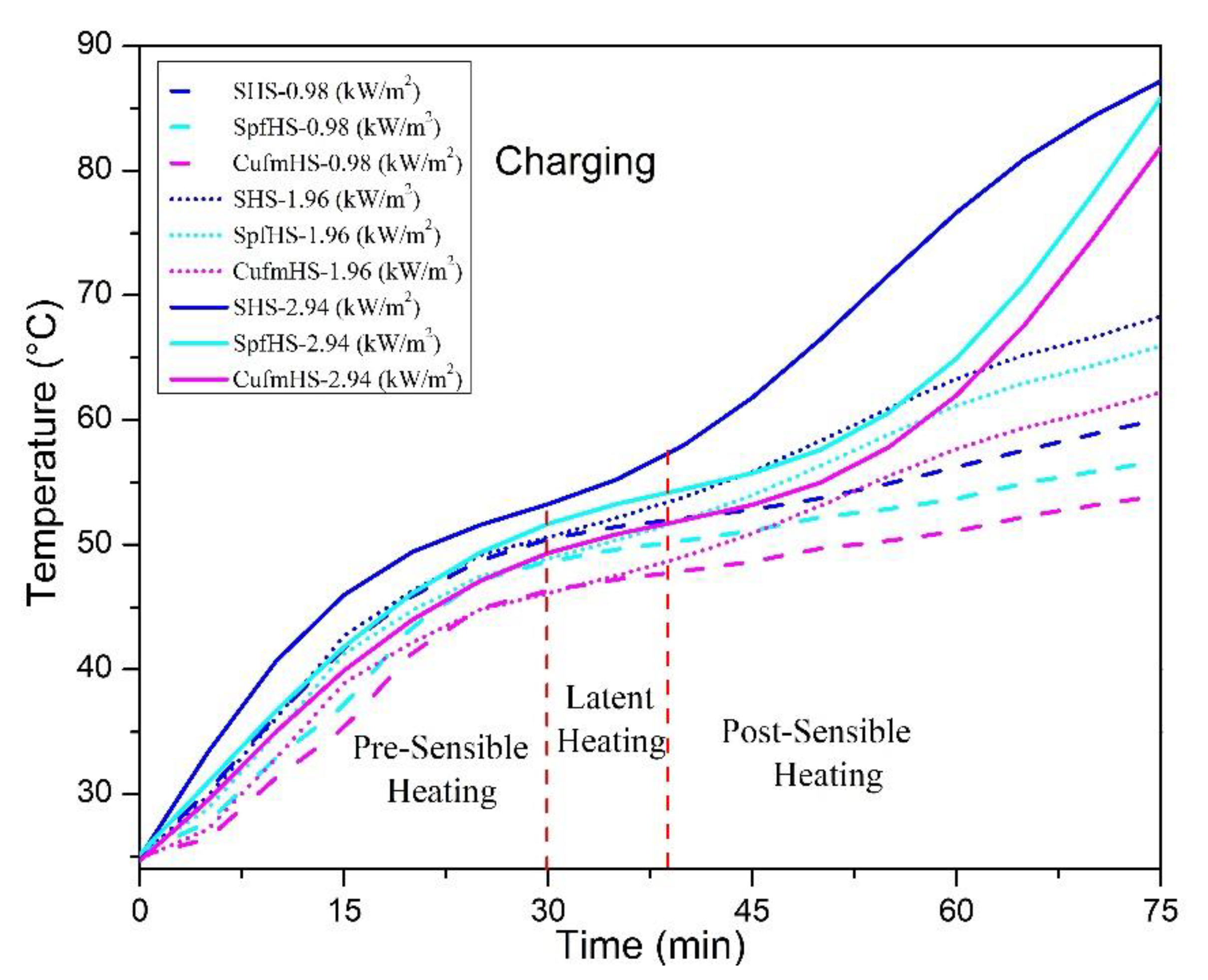
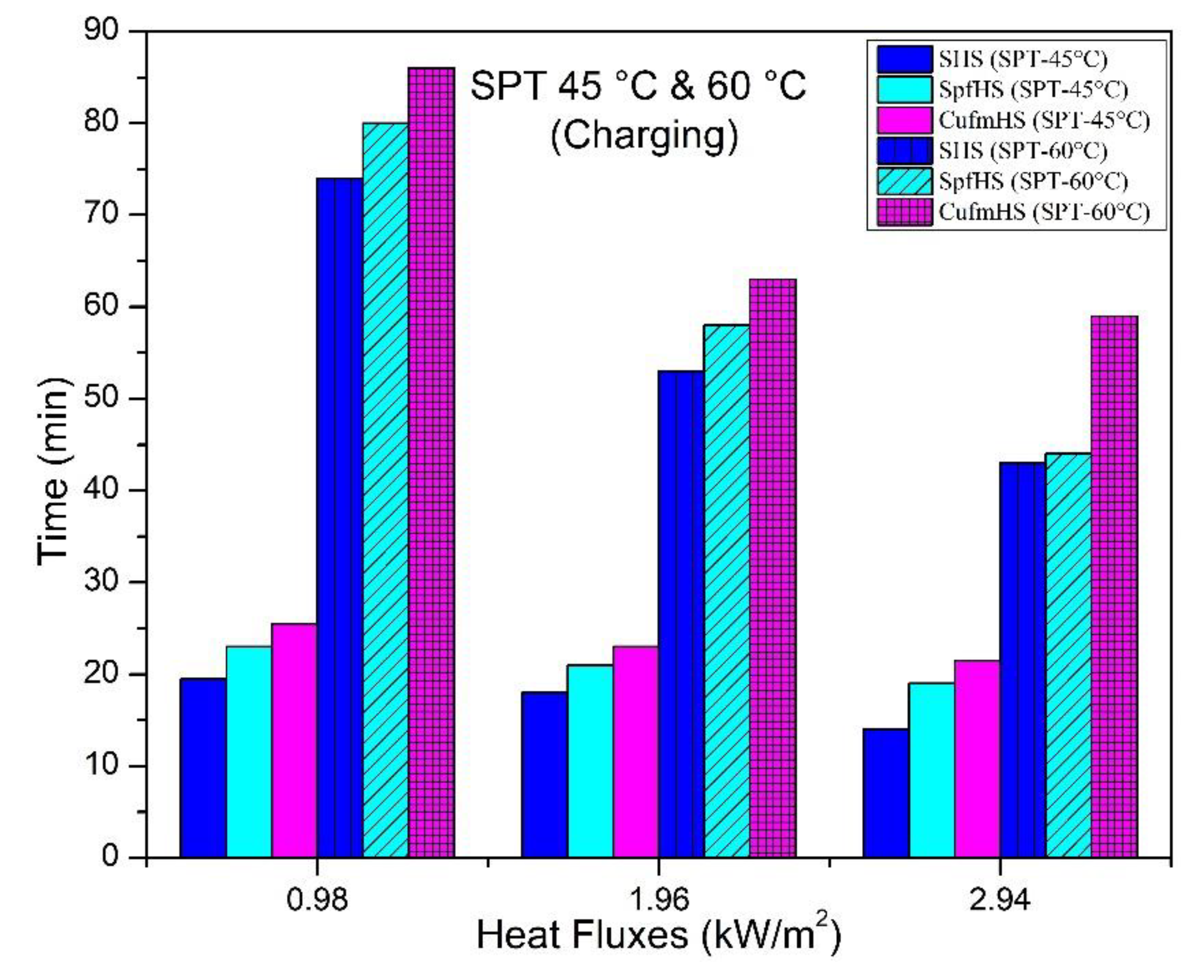
4.3.1. Charging Process

Figure 9 reflects SPT 45 °C and 60 °C during the charging process to evaluate the best performance of HS configurations. The SHS gained minimum time, and CufmHS exhibited maximum time to achieve SPT of 45 °C at 0.98 kW/m2 heat flux. The SHS, SpfHS, and CufmHS took 19.5, 23, and 25.5 min to reach the targeted SPT. This shows that the SpfHS took more time than the SHS but took less time against CufmHS. It is also evidenced that simple HS performance was lower than SpfHS and CufmHS at 1.96 kW·m−2. The duration observed by SHS, SpfHS, and CufmHS is 17, 23, and 25 min, respectively. At heat input of 2.94 kW/m2, it is noted that charging time was reduced through a proceeding larger heat flux ascribed to more heat absorbed by NePCM and the time experienced by three HSs is 14, 19, and 21.5 min, accordingly.
Considering SPT 60 °C, the performance of all three heat sinks was much better while comparing their performance in targeting SPT 45 °C. At 0.98 kW/m2 heat flux, the SHS took 74 min to target SPT 60 °C, while SpfHS and CufmHS did not reach during 75 min of charging, which shows an excellent thermal performance in monitoring subject SPT. The SpfHS and CufmHS took 80 and 86 min longer than the charging cycle minutes revealing the higher operating time of the electronic device. Three heat sinks took 53, 58, and 63 min to achieve SPT at 1.96 kW·m−2. The thermal performance of CufmHS was excellent and took 59 min maximum, while SHS was least performed during the charging cycle at a 2.94 kW·m−2.

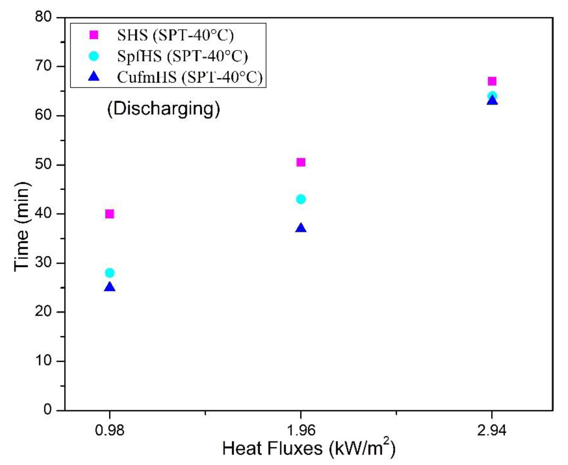
4.3.2. Discharging Process

The cooling performance of HS configurations against SPT 40 °C at different heat flux values was examined during the discharging process, as reflected in Figure 10. The SHS incorporated with NePCM of 0.25 wt% NPs showed the least performance while CufmHS represented better discharging performance The SHS, SpfHS, and CufmHS gained 40, 28, and 25 min, respectively. Less time observed for CufmHS showed more heat transferred towards the environment during the discharging process, reflecting the early cooling of the system. The SpfHS showed the second most efficient HS after CufmHS. At 2.94 kW/m2, the SHS, SpfHS, and CufmHS took 67, 64, and 63 min to achieve SPT of 40 °C. Once again, CufmHS took less time during the discharging process, which shows the most effective heat sink.

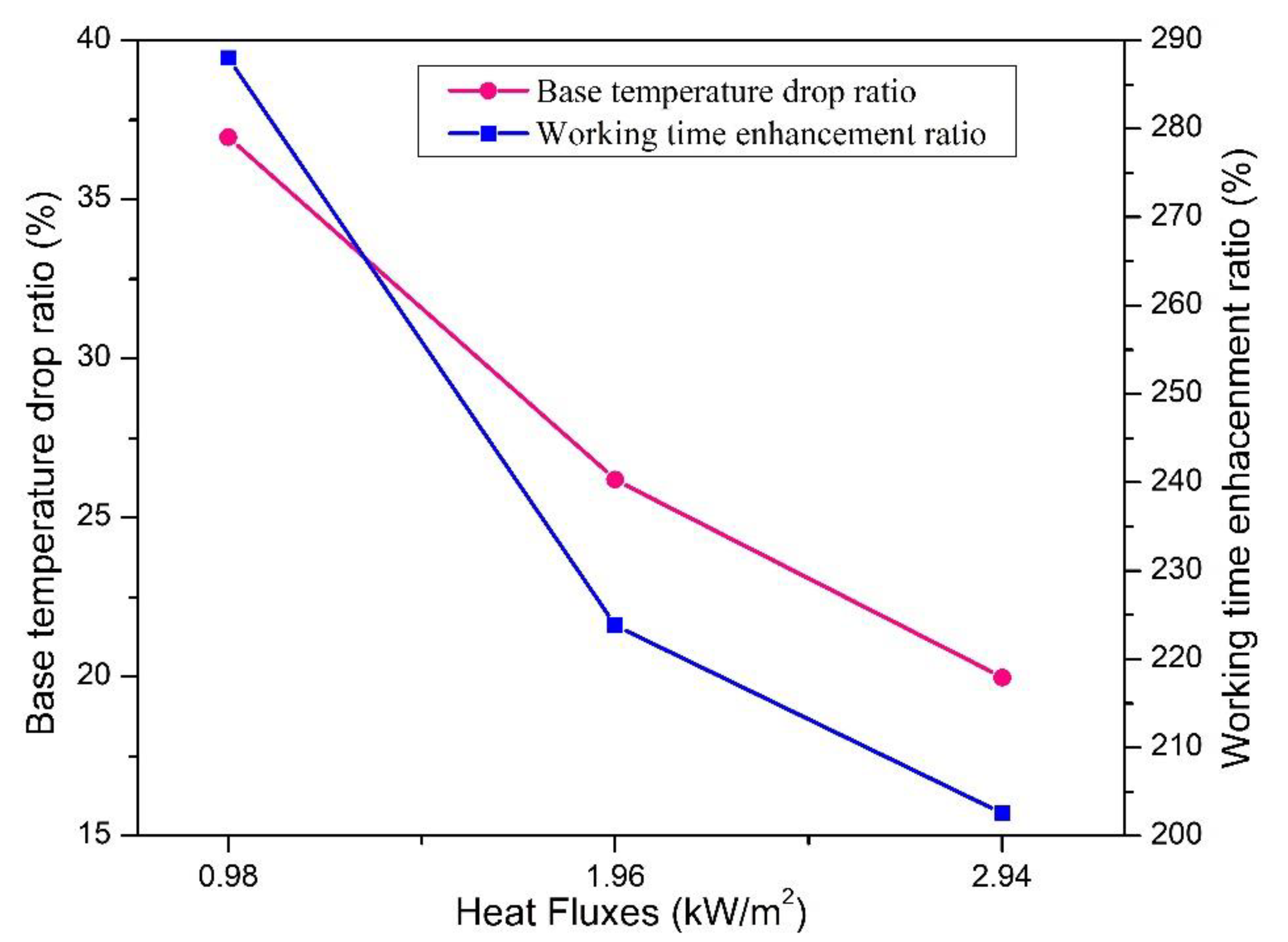
4.4. Effect of the Mass Concentration of Alumina NPs and Heat Flux on Tb Drop and Working Time Improvement

At various mass concentrations of alumina NPs and heat fluxes applied for various heat sinks (SHS, SpfHS, and CufmHS), the percentage drop of Tb and percentage improvement of working time at SPT-60 °C are compared in Table 6. The percentage drop of Tb and percentage improvement of working time can be calculated according to Equations (4) and (5).
%   D r o p   o f   b a s e   t e m p e r a t u r e = [ ( T P e a k e m p t y   H S ) ( T P e a k   H S ) ] 100 T P e a k e m p t y   H S
%   I m p r o v e m e n t   o f   w o r k i n g   t i m e = [ ( T i m e   S P T H S ) ( T i m e   S P T e m p t y   H S ) ] 100 T i m e   S P T e m p t y   H S
Table 6 shows that the base temperature drop ratio and working time enhancement ratio of tested HSs increased with the increasing mass concentration of NPs in PCM (RT_54HC) but decreased at high heat flux values. At 0.98 kW/m2 heat flux, the base temperature drop ratio and working time enhancement ratio increased for all mass concentrations of NPs for all three HS configurations. At subject heat flux, the performance parameters increased for SHS, SpfHS, and CufmHS. The CufmHS performance was better than other HSs by reason of the large covering region, which helped to decrease base temperature and improve working time. At 2.94 kW/m2 heat flux and 0.25 wt% of alumina NPs, the working time of heat sinks enhanced by 128.21%, 175.38%, and 202.56%, but Tb dropped 14.83%, 16.16%, and 19.98%, respectively. The SpfHS and CufmHS thermal performances were better than SHS. At three mass concentrations of NPs and heat fluxes, CufmHS showed excellent performance. At applied heat fluxes, the maximum enhancement in the working time of CufmHS against 0.25 wt% of NPs was 288, 223.81%, and 202.56%, respectively. PPI also plays a promising role in heat transfer enhancement, and it helps achieve SPT slowly, resulting in improved operational time. The SHS showed low thermal performance because it was unfinned. The thermal performance of SpfHS was better than SHS due to fins acting as thermal conductivity enhancers. However, the performance of CufmHS was outstanding regarding heat transfer, reducing base temperature and enhancing the device’s operating time owing to the prominent thermal dynamism of copper foam and surface area. Figure 11 shows the best thermal behavior of CufmHS for the thermal handling of electronic gadgets against applied heat fluxes and 0.25 wt% of alumina NPs. It was shown that the percentage of base temperature drop is enhanced as NPs mass fraction increases for the CufmHS, but the percentage improvement in operating time decreases as heat flux value propagates because more heat penetrates into PCM.

5. Conclusions

In the current experimental study, nanoparticles-based PCM were embedded into various HSs such as SHS, SpfHS, and CufmHS to investigate thermal behavior in reducing the base temperature and stretching the operating time of electronic devices at various heat fluxes. All results of NePCM based HSs were compared with empty SHS. The base temperature profile of empty SHS increased rapidly compared to NePCM filled HSs base temperature results, which may damage the electronic components. At applied three heat flux values, the base temperature of empty SHS was observed to be 76.4 °C, 84.3 °C, and 102.4 °C, respectively, at the tip of the charging operation. The introduction of PCM (RT-54HC) with NPs concentration (0.15, 0.20, and 0.25 wt%) reduced the base temperature and enhanced the working moment of the HSs. The thermal performance of SpfHS was found to be better than SHS, and the inclusion of copper foam further increased the performance due to the provision of a larger surface area. For the higher percentage of NPs, 0.25 wt%, provides the best outcome in CufmHS with temperature reduction of 36.95% and working time enhancement up to 288%. The performance of HSs was also investigated at SPT of 40 °C, and CufmHS showed negligible variation in cooling time as compared to SHS. Other types of metallic foams with highly conductive materials adopting hybrid cooling can also be suggested with direct use of alumina NPs based PCM to avoid oxidation and improve heat transfer for thermal management of electronics. In future studies, heat pipes and other active cooling systems in conjunction with NePCM can be tested for a better thermal performance of heat sinks in electronic devices.

Author Contributions

Conceptualization, I.Z., M.F. (Muhammad Farooq) and M.F. (Muhammad Farhan); methodology, experimentation, I.Z., M.F. (Muhammad Farooq) and A.Q.; data curation, formal analysis, writing—original draft, I.Z.; writing—review, editing and funding acquisition, M.A.A.; writing, review, editing and validation, S.A.; review, editing, and proof reading, M.Y.J., M.S., M.I., A.Q., M.U. and I.Z.; supervision, M.F. (Muhammad Farooq) and M.F. (Muhammad Farhan). All authors have read and agreed to the published version of the manuscript.

Funding

This research received no external funding.

Data Availability Statement

Not applicable.

Acknowledgments

The authors extend their appreciation to King Saud University for funding this work through Researchers Supporting Project number (RSP-2022R426), King Saud University, Riyadh, Saudi Arabia.

Conflicts of Interest

The authors declare no conflict of interest.

References

  1. Siddiqi, H.-R.; Qamar, A.; Shaukat, R.; Anwar, Z.; Amjad, M.; Farooq, M.; Abbas, M.M.; Imran, S.; Ali, H.; Khan, T.Y.; et al. Heat transfer and pressure drop characteristics of ZnO/DIW based nanofluids in small diameter compact channels: An experimental study. Case Stud. Therm. Eng. 2022, 39, 102441. [Google Scholar] [CrossRef]
  2. Qian, X.; Lee, S.W.; Yang, Y. Heat Transfer Coefficient Estimation and Performance Evaluation of Shell and Tube Heat Exchanger Using Flue Gas. Processes 2021, 9, 939. [Google Scholar] [CrossRef]
  3. Sohel Murshed, S.M.; Nieto de Castro, C.A. A critical review of traditional and emerging techniques and fluids for electronics cooling. Renew. Sustain. Energy Rev. 2017, 78, 821–833. [Google Scholar] [CrossRef]
  4. Viswanath, R.; Viswanath, R.; Wakharkar, V.; Watwe, A.; Lebonheur, V.; Group, M.; Corp, I. Thermal Performance Challenges from Silicon to Systems. 2000. Available online: http://citeseerx.ist.psu.edu/viewdoc/summary?doi=10.1.1.14.8322 (accessed on 6 May 2022).
  5. Kumar, A.; Kothari, R.; Sahu, S.K.; Kundalwal, S.I. Thermal performance of heat sink using nano-enhanced phase change material (NePCM) for cooling of electronic components. Microelectron. Reliab. 2021, 121, 114144. [Google Scholar] [CrossRef]
  6. Qian, X.; Lee, S.; Chandrasekaran, R.; Yang, Y.; Caballes, M.; Alamu, O.; Chen, G. Electricity Evaluation and Emission Characteristics of Poultry Litter Co-Combustion Process. Appl. Sci. 2019, 9, 4116. [Google Scholar] [CrossRef] [Green Version]
  7. Bhattacharyya, S.; Vishwakarma, D.K.; Srinivasan, A.; Soni, M.K.; Goel, V.; Sharifpur, M.; Ahmadi, M.H.; Issakhov, A.; Meyer, J. Thermal performance enhancement in heat exchangers using active and passive techniques: A detailed review. J. Therm. Anal. Calorim. 2022, 147, 9229–9281. [Google Scholar] [CrossRef]
  8. Watson, J.; Castro, G. A review of high-temperature electronics technology and applications. J. Mater. Sci. Mater. Electron. 2015, 26, 9226–9235. [Google Scholar] [CrossRef]
  9. Elias, C.N.; Stathopoulos, V.N. A comprehensive review of recent advances in materials aspects of phase change materials in thermal energy storage. Energy Procedia 2019, 161, 385–394. [Google Scholar] [CrossRef]
  10. Tofani, K.; Tiari, S. Nano-Enhanced phase change materials in latent heat thermal energy storage systems: A review. Energies 2021, 14, 3821. [Google Scholar] [CrossRef]
  11. Eanest Jebasingh, B.; Valan Arasu, A. A comprehensive review on latent heat and thermal conductivity of nanoparticle dispersed phase change material for low-temperature applications. Energy Storage Mater. 2020, 24, 52–74. [Google Scholar] [CrossRef]
  12. Leong, K.Y.; Chew, S.P.; Gurunathan, B.A.; Ku Ahmad, K.Z.; Ong, H.C. An experimental approach to investigate thermal performance of paraffin wax and 1-hexadecanol based heat sinks for cooling of electronic system. Int. Commun. Heat Mass Transf. 2019, 109, 104365. [Google Scholar] [CrossRef]
  13. Li, W.Q.; Guo, S.J.; Tan, L.; Liu, L.L.; Ao, W. Heat transfer enhancement of nano-encapsulated phase change material (NEPCM) using metal foam for thermal energy storage. Int. J. Heat Mass Transf. 2021, 166, 120737. [Google Scholar] [CrossRef]
  14. Ijaz, M.; Farhan, M.; Farooq, M.; Moeenuddin, G.; Nawaz, S.; Soudagar, M.E.M.; Saqib, H.M.; Ali, Q. Numerical investigation of particles characteristics on cyclone performance for sustainable environment. Part. Sci. Technol. 2021, 39, 495–503. [Google Scholar] [CrossRef]
  15. Ur Rehman, S.; Farooq, M.; Qamar, A.; Usman, M.; Ahmad, G.; Sultan, M.; Wajid Saleem, M.; Hussain, I.; Imran, M.; Ali, Q.; et al. Experimental investigation to thermal performance of different photo voltaic modules for efficient system design. Alexandria Eng. J. 2022, 61, 12623–12634. [Google Scholar] [CrossRef]
  16. Sattar, A.; Farooq, M.; Amjad, M.; Saeed, M.A.; Nawaz, S.; Mujtaba, M.A.; Anwar, S.; El-Sherbeeny, A.M.; Soudagar, M.E.M.; Bandarra Filho, E.P.; et al. Performance evaluation of a direct absorption collector for solar thermal energy conversion. Energies 2020, 13, 4956. [Google Scholar] [CrossRef]
  17. Alam, M.W.; Bhattacharyya, S.; Souayeh, B.; Dey, K.; Hammami, F.; Rahimi-Gorji, M.; Biswas, R. CPU heat sink cooling by triangular shape micro-pin-fin: Numerical study. Int. Commun. Heat Mass Transf. 2020, 112, 104455. [Google Scholar] [CrossRef]
  18. Kazemi, M.; Hosseini, M.J.; Ranjbar, A.A.; Bahrampoury, R. Improvement of longitudinal fins configuration in latent heat storage systems. Renew. Energy 2018, 116, 447–457. [Google Scholar] [CrossRef]
  19. Zhu, Z.Q.; Huang, Y.K.; Hu, N.; Zeng, Y.; Fan, L.W. Transient performance of a PCM-based heat sink with a partially filled metal foam: Effects of the filling height ratio. Appl. Therm. Eng. 2018, 128, 966–972. [Google Scholar] [CrossRef]
  20. Dammak, K.; El Hami, A. Thermal reliability-based design optimization using Kriging model of PCM based pin fin heat sink. Int. J. Heat Mass Transf. 2021, 166, 120745. [Google Scholar] [CrossRef]
  21. Arshad, A.; Ali, H.M.; Khushnood, S.; Jabbal, M. Experimental investigation of PCM based round pin-fin heat sinks for thermal management of electronics: Effect of pin-fin diameter. Int. J. Heat Mass Transf. 2018, 117, 861–872. [Google Scholar] [CrossRef]
  22. Jilte, R.; Ahmadi, M.H.; Kumar, R.; Kalamkar, V.; Mosavi, A. Cooling Performance of a Novel Circulatory Flow Concentric Multi-Channel Heat Sink with Nanofluids. Nanomaterials 2020, 10, 647. [Google Scholar] [CrossRef] [PubMed] [Green Version]
  23. Manoj Kumar, P.; Saminathan, R.; Sumayli, A.; Mittal, M.; Abishek, A.S.; Atharsh Kumaar, A.S.; Reddy, T.D.K.; Rinawa, M.L. Experimental analysis of a heat sink for electronic chipset cooling using a nano improved PCM (NIPCM). Mater. Today Proc. 2022, 56, 1527–1531. [Google Scholar] [CrossRef]
  24. Arshad, A.; Jabbal, M.; Faraji, H.; Talebizadehsardari, P.; Bashir, M.A.; Yan, Y. Numerical study of nanocomposite phase change material-based heat sink for the passive cooling of electronic components. Heat Mass Transf. Stoffuebertragung 2021, 15, 1–15. [Google Scholar] [CrossRef]
  25. Yang, X.; Yu, J.; Guo, Z.; Jin, L.; He, Y.L. Role of porous metal foam on the heat transfer enhancement for a thermal energy storage tube. Appl. Energy 2019, 239, 142–156. [Google Scholar] [CrossRef]
  26. Wang, S.; Xing, Y.; Hao, Z.; Yin, J.; Hou, X.; Wang, Z. Experimental study on the thermal performance of PCMs based heat sink using higher alcohol/graphite foam. Appl. Therm. Eng. 2021, 198, 117452. [Google Scholar] [CrossRef]
  27. Farzanehnia, A.; Khatibi, M.; Sardarabadi, M.; Passandideh-Fard, M. Experimental investigation of multiwall carbon nanotube/paraffin based heat sink for electronic device thermal management. Energy Convers. Manag. 2019, 179, 314–325. [Google Scholar] [CrossRef]
  28. Fan, L.W.; Zhu, Z.Q.; Zeng, Y.; Xiao, Y.Q.; Liu, X.L.; Wu, Y.Y.; Ding, Q.; Yu, Z.T.; Cen, K.F. Transient performance of a PCM-based heat sink with high aspect-ratio carbon nanofillers. Appl. Therm. Eng. 2015, 75, 532–540. [Google Scholar] [CrossRef]
  29. Alimohammadi, M.; Aghli, Y.; Alavi, E.S.; Sardarabadi, M.; Passandideh-Fard, M. Experimental investigation of the effects of using nano/phase change materials (NPCM) as coolant of electronic chipsets, under free and forced convection. Appl. Therm. Eng. 2017, 111, 271–279. [Google Scholar] [CrossRef]
  30. Bayat, M.; Faridzadeh, M.R.; Toghraie, D. Investigation of finned heat sink performance with nano enhanced phase change material (NePCM). Therm. Sci. Eng. Prog. 2018, 5, 50–59. [Google Scholar] [CrossRef]
  31. Zhang, P.; Meng, Z.N.; Zhu, H.; Wang, Y.L.; Peng, S.P. Melting heat transfer characteristics of a composite phase change material fabricated by paraffin and metal foam. Appl. Energy 2017, 185, 1971–1983. [Google Scholar] [CrossRef]
  32. Zhao, L.; Xing, Y.; Liu, X. Experimental investigation on the thermal management performance of heat sink using low melting point alloy as phase change material. Renew. Energy 2020, 146, 1578–1587. [Google Scholar] [CrossRef]
  33. Joseph, M.; Sajith, V. Graphene enhanced paraffin nanocomposite based hybrid cooling system for thermal management of electronics. Appl. Therm. Eng. 2019, 163, 114342. [Google Scholar] [CrossRef]
  34. Farooq, M.; Farhan, M.; Ahmad, G.; Tahir, Z.U.R.; Usman, M.; Sultan, M.; Saad Hanif, M.; Imran, M.; Anwar, S.; El-Sherbeeny, A.M.; et al. Thermal performance enhancement of nanofluids based parabolic trough solar collector (NPTSC) for sustainable environment. Alex. Eng. J. 2022, 61, 8943–8953. [Google Scholar] [CrossRef]
  35. Jurčević, M.; Nižetić, S.; Arıcı, M.; Ocłoń, P. Comprehensive analysis of preparation strategies for phase change nanocomposites and nanofluids with brief overview of safety equipment. J. Clean. Prod. 2020, 274, 122963. [Google Scholar] [CrossRef]
  36. Ali, H.M.; Babar, H.; Shah, T.R.; Sajid, M.U.; Qasim, M.A.; Javed, S. Preparation Techniques of TiO2 Nanofluids and Challenges: A Review. Appl. Sci. 2018, 8, 587. [Google Scholar] [CrossRef] [Green Version]
  37. Arshad, A.; Jabbal, M.; Yan, Y. Preparation and characteristics evaluation of mono and hybrid nano-enhanced phase change materials (NePCMs) for thermal management of microelectronics. Energy Convers. Manag. 2020, 205, 112444. [Google Scholar] [CrossRef]
  38. Aurangzeb, M.; Noor, F.; Qamar, A.; Shah, A.N.; Kumam, P.; Shah, Z.; Shutaywi, M. Investigation of enhancement in the thermal response of phase change materials through nano powders. Case Stud. Therm. Eng. 2022, 29, 101654. [Google Scholar] [CrossRef]
  39. Qamar, A.; Anwar, Z.; Ali, H.; Imran, S.; Shaukat, R.; Abbas, M.M. Experimental investigation of dispersion stability and thermophysical properties of ZnO/DIW nanofluids for heat transfer applications. Alex. Eng. J. 2022, 61, 4011–4026. [Google Scholar] [CrossRef]
  40. Tariq, S.L.; Ali, H.M.; Akram, M.A.; Janjua, M.M. Experimental investigation on graphene based nanoparticles enhanced phase change materials (GbNePCMs) for thermal management of electronic equipment. J. Energy Storage 2020, 30, 101497. [Google Scholar] [CrossRef]
Figure 1. PCMs thermal conductivity enhancement techniques.
Energies 15 08416 g001
Figure 2. Test setup for thermal performance of NePCM-based heat sinks.
Energies 15 08416 g002
Figure 3. (a) Isometric views of the square pin-fin heat sink (mm). (b) Pictorial views of the SHS, SpfHS, and CufmHS.
Energies 15 08416 g003
Figure 4. Sequence of steps for NePCM preparation.
Energies 15 08416 g004
Figure 5. (a) SEM spectrum of alumina NPs (b) EDX spectrum of alumina NPs.
Energies 15 08416 g005
Figure 6. Test setup validation to investigate HS performance [40].
Energies 15 08416 g006
Figure 7. Various HSs time-temperature behavior at heat fluxes (a) 0.98 kW·m−2 (b) 1.96 kW·m−2 (c) 2.94 kW·m−2.
Energies 15 08416 g007
Figure 8. Base temperature distribution of heat sinks at various heat fluxes.
Energies 15 08416 g008
Figure 9. Operational time comparison at SPTs (45–60 °C) of different HSs for various heat fluxes.
Energies 15 08416 g009
Figure 10. Operational time SPT (40 °C) comparison of various heat sinks against various heat fluxes.
Energies 15 08416 g010
Figure 11. Comparison of baseline temperature reduction ratio and operating time enhancement ratio of Cu foam heat sink.
Energies 15 08416 g011
Table 1. Summary of various heat sinks used for passive cooling of electronic components.
Sr.
No
PCM, NPs/(wt%)Method/Melting
Point (°C)
HS Size
(mm3)
HS
Type
Metallic
Foams
Heat Input
(kW/m2)/W
Sonication Time
(Hr)
Ref.
1Paraffin wax,
MWCNT/
(0.2, 2)
Experimental
(46–48)
73 × 68 × 44.5Plate fins-2–65[27]
2PCM.
CNT, GNP/
(0.3, 1, 3)
Experimental
(50)
80 × 80 × 30Simple-40, 80 and 1200.83[28]
3Mn(NO3)2,
Fe3O4/(1)
Experimental
(37)
75 × 75 × 40Plate fins-5.5–22.54[29]
4RT-44,
CuO, Al2O3/
(2)
Numerical
(41–45)
50 × 50 × 40Plate fins-10, 20 and 30-[30]
5Paraffin wax,Numerical and
Experimental
(52–54)
100 × 100 × 10SimpleCu foam--[31]
6Bi-Pb-Sn-Cd,Experimental
(69.59)
104 × 104 × 25SimpleCu foam2, 3 and 4-[32]
7PCM,
GNP
Experimental
(58–60)
42 × 42 × 32Plate fins-5–2015[33]
Note: PCMs are commercially available according to their melting point. Paraffin wax, Mn(NO3)2, Bi-Pb-Sn-Cd, and RT-44 are distinct categories of PCMs (organic & inorganic) procurable in the trading center synthesized by various companies. PCM (RT-44) is synthesized by Rubitherm Technologies, a German company, whose melting point is 44 °C.
Table 2. Properties of the metallic foam.
MaterialPores per Inch (PPI) Purity
(%)
Porosity
(%)
Specific Heat (kJ/kg·K)Density (kg/m3)Thermal Conductivity (W/m·K)
Cu Foam32>99940.38421387
Table 3. Locations of eleven thermocouples placed on the heat sink.
ThermocouplesB1–B2P1–P2P3–P4P5–P6P7–P8T9
Positions (mm)Heat sink Base08.717.426.1Room
Table 4. Properties of the PCM and alumina NPs.
MaterialMelting Point
(°C)
Latent Heat
(kJ/kg)
Density
(kg/m3)
Specific Heat (kJ/kg·K)Purity
(%)
Thermal
Conductivity (W/m·K)
References
RT-54HC542000.85 (s), 0.8 (l)2-0.2Authors Work
Al2O3 NPs2977--2.4010035Auregzaib et al. [38]
Table 5. Working time enhancement of heat sinks at various SPTs.
Heat Sink TypeChargingChargingDischarging
Time to Access SPT-45 °C
(s)
Time to Access SPT-60 °C
(s)
Time to Access SPT-40 °C
(s)
kW/m20.981.962.940.981.962.940.981.962.94
SHS11701080840444031802580240030304020
SpfHS138012601140480043803240168025803840
CufmHS153013801290518037803540150022203780
Table 6. Comparison of the Tb drop ratio and working time improvement ratio.
0.98 kW/m21.96 kW/m22.94 kW/m2
NPs (wt%)Ratio
(%)
SHSSpfHSCufmHSSHSSpfHSCufmHSSHSSpfHSCufmHS
0.15Tb drop 2024.2231.5717.4919.7723.2213.1515.0616.99
Working time enhancement 180228252142161.90185.71110.26157.95182.05
0.20Tb drop 20.6125.1134.9418.2120.5924.731415.6318.38
Working time enhancement192236276150171.43204.76121.54167.69192.31
0.25Tb drop 21.3225.7536.9518.9621.7626.2014.8316.1619.98
Working time enhancement 198244288158.57180.95223.81128.21175.38202.56
Publisher’s Note: MDPI stays neutral with regard to jurisdictional claims in published maps and institutional affiliations.

