
Thermal Management Technologies Used for High Heat Flux Automobiles and Aircraft: A Review


Abstract
1. Introduction
2. Active Methods
2.1. Forced Air Cooling
2.2. Indirect Contact Cold Plate Cooling
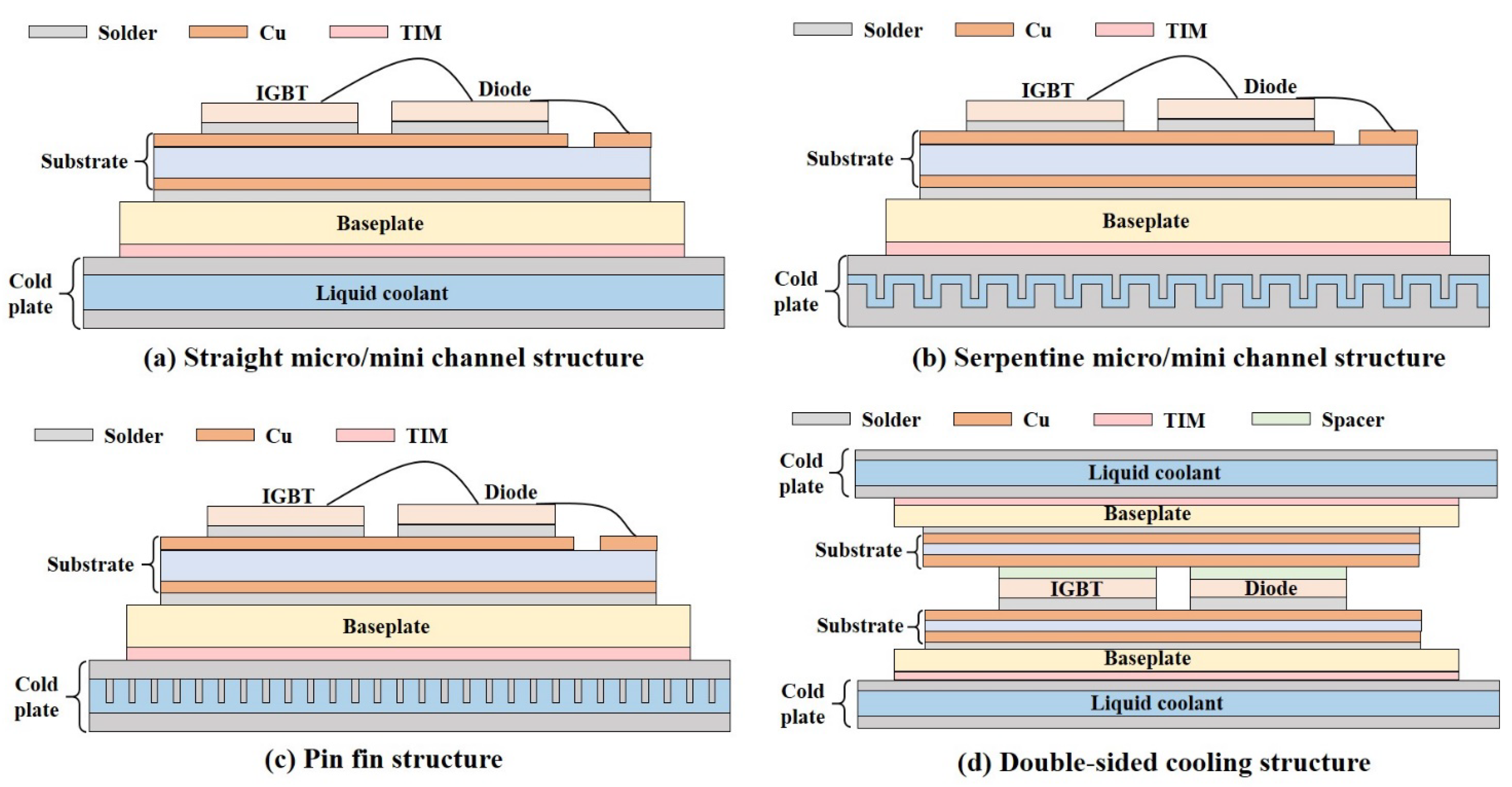
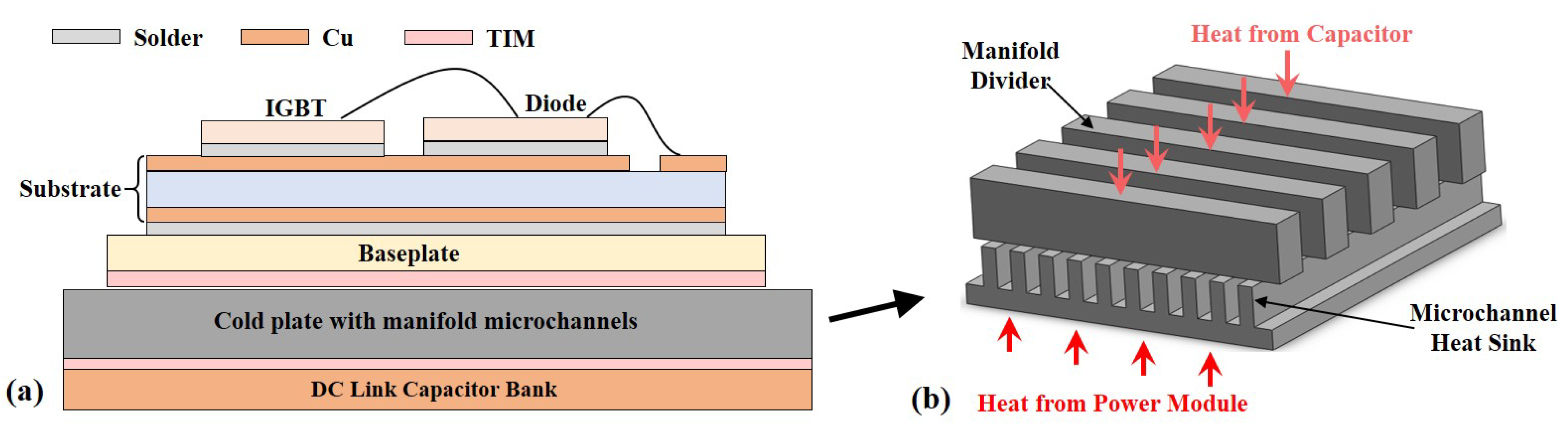
2.2.1. Single-Phase Cold Plate
2.2.2. Two-Phase Cold Plate
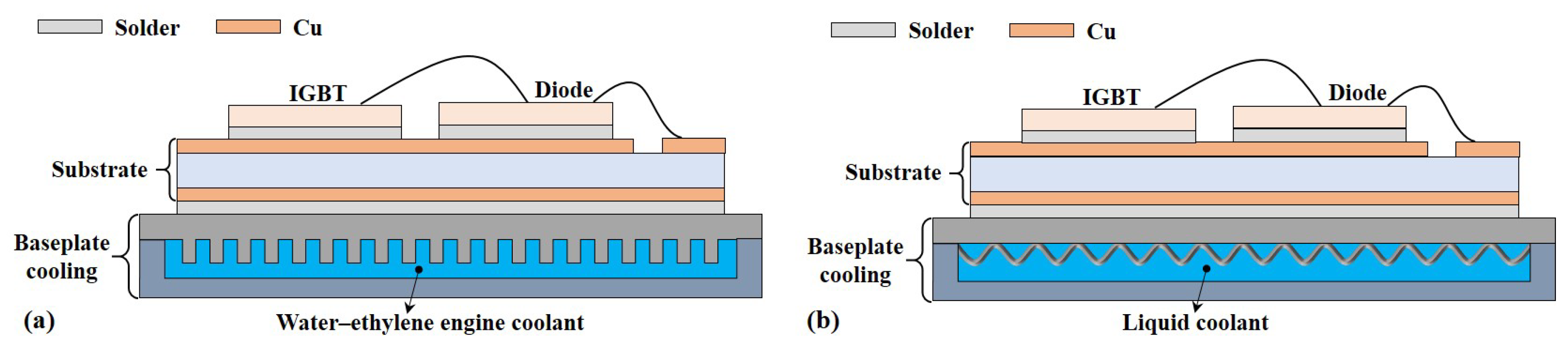
2.3. Direct Contact Baseplate Cooling
2.3.1. Single-Phase Baseplate Cooling
2.3.2. Two-Phase Baseplate Cooling
2.4. Jet Impingement Cooling
2.5. Spray Cooling
3. Passive Methods
3.1. Heat Pipes
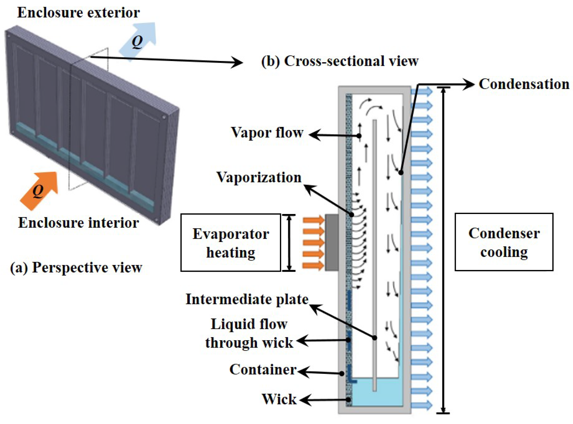
3.1.1. Flat Heat Pipe
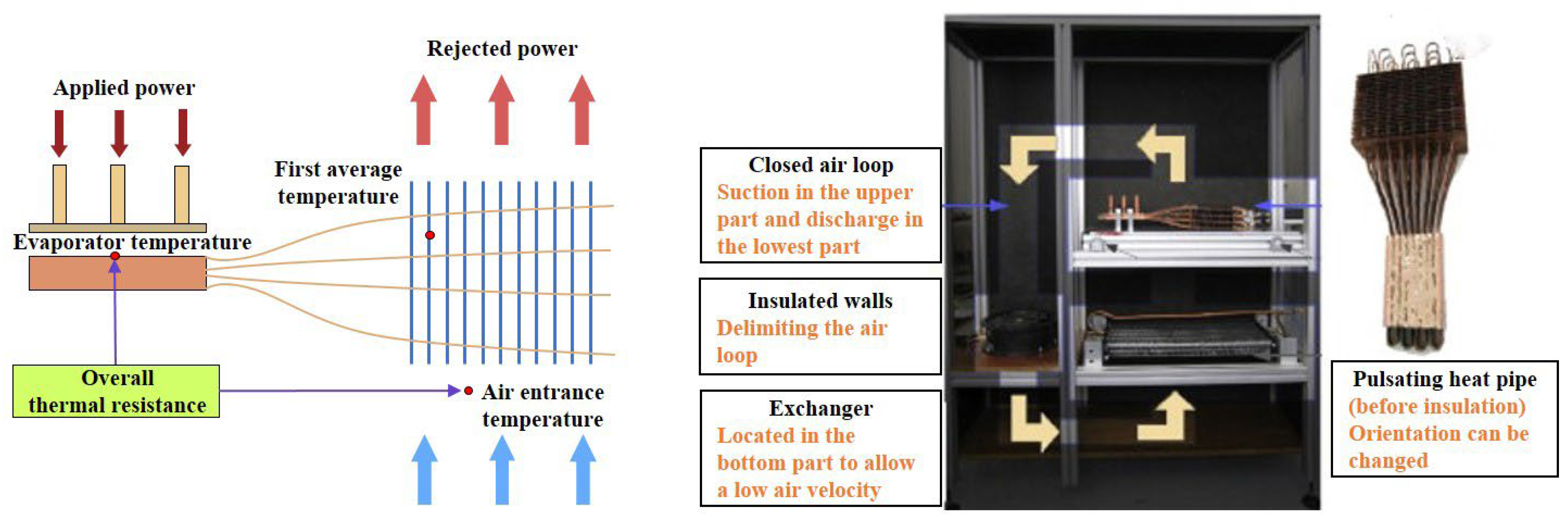
3.1.2. Pulsating Heat Pipe (PHP)
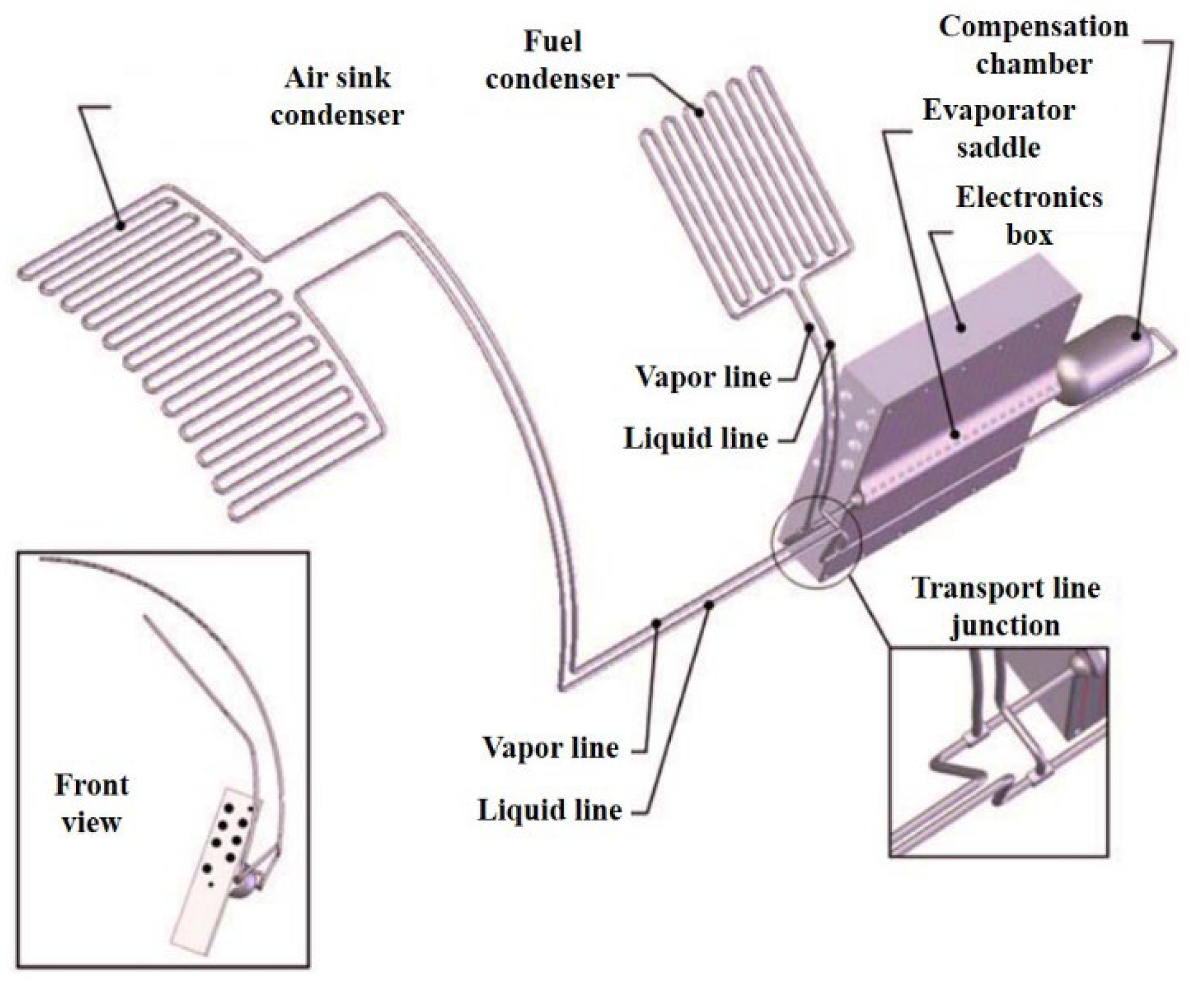
3.1.3. Loop Heat Pipe (LHP)
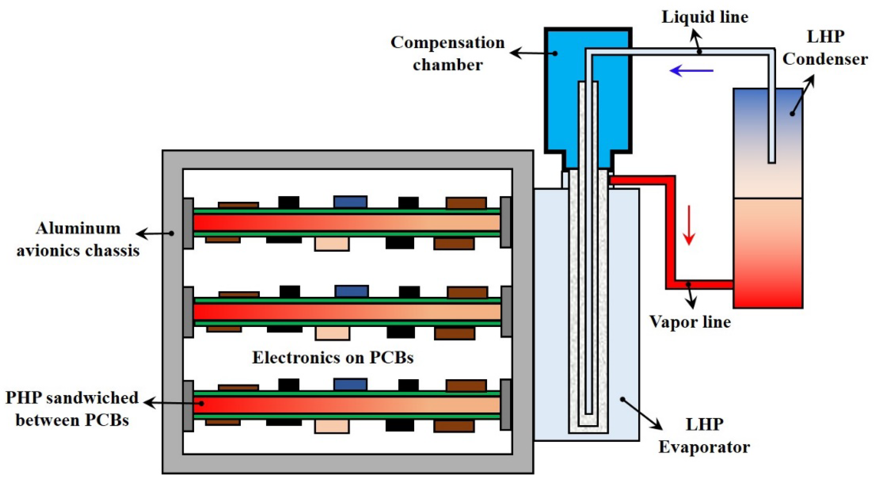
3.1.4. Heat-Pipe-Based Hybrid Cooling Scheme
3.2. Phase Change Materials (PCMs)
4. Environmental Influences on the TMS
4.1. Vibrations and Shock
4.1.1. Effects of Vibrations and Shock on Active TMS
4.1.2. Effects of Vibrations and Shocks on Heat Pipes
4.1.3. Effects of Vibrations on PCMs
4.2. Acceleration and Gravity
4.2.1. Effects of Gravity on Active TMS
4.2.2. Effects of Acceleration on Heat Pipes
4.2.3. Effects of Gravity on Heat Pipes
4.2.4. Effects of Gravity on PCMs
5. Conclusions and Remarks
Author Contributions
Funding
Conflicts of Interest
Nomenclature
| AEV | All-electric vehicle |
| CHF | critical heat flux |
| CTPL | capillary two-phase loop |
| DBC | directed bonding copper |
| ECU | engine control unit |
| EV | electric vehicle |
| HEV | hybrid electric vehicle |
| LHP | loop heat pipe |
| MEA | more electric aircraft |
| MOSFET | metal–oxide–semiconductor field-effect transistor |
| PCM | phase change material |
| PCU | power control unit |
| PHP | pulsating heat pipe |
| TCU | transmission control unit |
| TEC | thermoelectric cooler |
| TIM | thermal interface material |
| TMS | thermal management system |
| ICEV | internal combustion engine vehicle |
| IGBT | insulated gate bipolar translators |
| VOF | volume of fluid |
| WBG | wide bandgap |
References
- Diaz, M.N. Electric Vehicles: A Primer on Technology and Selected Policy Issues; R46231; Congressional Research Service: Washington, DC, USA, 2020.
- Huque, M.A.; Islam, S.K.; Blalock, B.J.; Su, C.; Vijayaraghavan, R.; Tolbert, L.M. Silicon-on-Insulator Based High-Temperature Electronics for Automotive Applications. In Proceedings of the 2008 IEEE International Symposium on Industrial Electronics, Cambridge, UK, 30 June–2 July 2008. [Google Scholar]
- Nakayama, W.; Suzuki, O.; Hara, Y. Thermal Management of Electronic and Electrical Devices in Automobile Environment. In Proceedings of the 2009 IEEE Vehicle Power and Propulsion Conference, Dearborn, MI, USA, 7–10 September 2009. [Google Scholar]
- Johnson, R.W.; Evans, J.L.; Jacobsen, P.; Thompson, J.R.R.; Christopher, M. The Changing Automotive Environment: High-Temperature Electronics. IEEE Trans. Electron. Packag. Manuf. 2004, 27, 164–176. [Google Scholar] [CrossRef]
- Langmaack, N.; Tareilus, G.; Henke, M. Modular Power Electronics for Electric Vehicles and Aviation Applications. In Proceedings of the 2019 IEEE 13th International Conference on Power Electronics and Drive Systems (PEDS), Toulouse, France, 9–12 July 2019. [Google Scholar]
- Liu, X.; Wu, Z.; Yan, Y.; Kang, Y.; Chen, C. A Novel Double-Sided Cooling Inverter Leg for High Power Density EV Based on Customized SiC Power Module. In Proceedings of the 2020 IEEE Energy Conversion Congress and Exposition (ECCE), Detroit, MI, USA, 11–15 October 2020. [Google Scholar]
- Lai, J.-S.; Yu, W.; Qian, H.; Sun, P.; Ralston, P.; Meehan, K. High Temperature Device Characterization for Hybrid Electric Vehicle Traction Inverters. In Proceedings of the 2009 Twenty-Fourth Annual IEEE Applied Power Electronics Conference and Exposition, Washington, DC, USA, 15–19 February 2009. [Google Scholar]
- Passmore, B.S.; Lostetter, A.B. A review of SiC power module packaging technologies Attaches, interconnections, and advanced heat transfer. In Proceedings of the 2017 IEEE International Workshop on Integrated Power Packaging (IWIPP), Delft, The Netherlands, 5–7 April 2017. [Google Scholar]
- Hassan, A.; Savaria, Y.; Sawan, M. Electronics and Packaging Intended for Emerging Harsh Environment Applications: A Review. IEEE Trans. Very Large Scale Integr. VLSI Syst. 2018, 26, 2085–2098. [Google Scholar] [CrossRef]
- Jankowski, N.R.; McCluskey, F.P. A review of phase change materials for vehicle component thermal buffering. Appl. Energy 2014, 113, 1525–1561. [Google Scholar] [CrossRef]
- Robles, J. A system level view of Avionics—Vetronics cooling options for harsh environment two-level maintenance systems. In Proceedings of the Twentieth Annual IEEE Semiconductor Thermal Measurement and Management Symposium, San Jose, CA, USA, 11 March 2004. [Google Scholar]
- Korta, J.; Skruch, P.; Holon, K. Reliability of Automotive Multidomain Controllers: Advancements in electronics cooling technologies. IEEE Veh. Technol. Mag. 2021, 16, 86–94. [Google Scholar] [CrossRef]
- Yang, D.; Liu, D.; Driel, W.D.v.; Scholten, H.; Goumans, L.; Faria, R. Advanced reliability study on high temperature automotive electronics. In Proceedings of the 2010 11th International Conference on Electronic Packaging Technology & High Density Packaging, Xi’an, China, 16–19 August 2010. [Google Scholar]
- Tang, X.; Park, C. Vibration/Shock-Tolerant Capillary Two-Phase Loop Technology for Vehicle Thermal Control. In Proceedings of the 2008 ASME Summer Heat Transfer Conference, Jacksonville, FL, USA, 10–14 August 2008. [Google Scholar]
- Ellis, M.; Montgomery, J. Passive Thermal Management for Avionics in High Temperature Environments. In Proceedings of the SAE 2014 Aerospace Systems and Technology Conference, Cincinnati, OH, USA, 23–25 September 2014. [Google Scholar]
- Brewer, R.A. High temperature electronics for demanding aircraft applications. In Proceedings of the 2018 International Applied Computational Electromagnetics Society Symposium (ACES), Denver, CO, USA, 25–29 March 2018. [Google Scholar]
- Mc Cluskey, P.; Saadon, Y.; Yao, Z.; Shah, J.; Kizito, J. Thermal Management Challenges in Turbo-Electric and Hybrid Electric Propulsion. In Proceedings of the 2018 International Energy Conversion Engineering Conference, Cincinnati, OH, USA, 9–11 July 2018. [Google Scholar]
- Jafari, S.; Nikolaidis, T. Thermal Management Systems for Civil Aircraft Engines: Review, Challenges and Exploring the Future. Appl. Sci. 2018, 8, 2044. [Google Scholar] [CrossRef]
- Wileman, A.J.; Aslam, S.; Perinpanayagam, S. A road map for reliable power electronics for more electric aircraft. Prog. Aerosp. Sci. 2021, 127, 100739. [Google Scholar] [CrossRef]
- Mao, Y.F.; Li, Y.Z.; Wang, J.X.; Xiong, K.; Li, J.X. Cooling Ability/Capacity and Exergy Penalty Analysis of Each Heat Sink of Modern Supersonic Aircraft. Entropy 2019, 21, 223. [Google Scholar] [CrossRef]
- Pal, D.; Severson, M. Liquid Cooled System for Aircraft Power Electronics Cooling. In Proceedings of the 2017 16th IEEE Intersociety Conference on Thermal and Thermomechanical Phenomena in Electronic Systems (ITherm), Orlando, FL, USA, 30 May–2 June 2017. [Google Scholar]
- Ohadi, M.; Qi, J. Thermal Management of Harsh-Environment Electronics. In Proceedings of the Twentieth Annual IEEE Semiconductor Thermal Measurement and Management Symposium (SEMI-THERM), San Jose, CA, USA, 11 March 2004; pp. 231–240. [Google Scholar]
- Garimella, S.V.; Fleischer, A.S.; Murthy, J.Y.; Keshavarzi, A.; Prasher, R.; Patel, C.; Bhavnani, S.H.; Venkatasubramanian, R.; Mahajan, R.; Joshi, Y.; et al. Thermal Challenges in Next-Generation Electronic Systems. IEEE Trans. Compon. Packag. Technol. 2008, 31, 801–815. [Google Scholar] [CrossRef]
- Laloya, E.; Lucia, O.; Sarnago, H.; Burdio, J.M. Heat Management in Power Converters: From State of the Art to Future Ultrahigh Efficiency Systems. IEEE Trans. Power Electron. 2016, 31, 7896–7908. [Google Scholar] [CrossRef]
- Iradukunda, A.-C.; Huitink, D.R.; Luo, F. A Review of Advanced Thermal Management Solutions and the Implications for Integration in High-Voltage Packages. IEEE J. Emerg. Sel. Top. Power Electron. 2020, 8, 256–271. [Google Scholar] [CrossRef]
- Ghaisas, G.; Krishnan, S. A Critical Review and Perspective on Thermal Management of Power Electronics Modules for Inverters and Converters. Trans. Indian Natl. Acad. Eng. 2021, 7, 47–60. [Google Scholar] [CrossRef]
- Mathew, J.; Krishnan, S. A Review on Transient Thermal Management of Electronic Devices. J. Electron. Packag. 2021, 144, 010801. [Google Scholar] [CrossRef]
- Zuo, J.; Anderson, W.; Bonner, R. Advanced Thermal Management Technologies for High Power Automotive Equipment. In Proceedings of the National Defense Industrial Association Ground Vehicle Power and Energy Workshop, Troy, MI, USA, 18–19 November 2008. [Google Scholar]
- Broughton, J.; Smet, V.; Tummala, R.R.; Joshi, Y.K. Review of Thermal Packaging Technologies for Automotive Power Electronics for Traction Purposes. J. Electron. Packag. 2018, 140, 040801. [Google Scholar] [CrossRef]
- Lajunen, A.; Yang, Y.; Emadi, A. Recent Developments in Thermal Management of Electrified Powertrains. IEEE Trans. Veh. Technol. 2018, 67, 11486–11499. [Google Scholar] [CrossRef]
- López, I.; Ibarra, E.; Matallana, A.; Andreu, J.; Kortabarria, I. Next generation electric drives for HEV/EV propulsion systems: Technology, trends and challenges. Renew. Sustain. Energy Rev. 2019, 114, 109336. [Google Scholar] [CrossRef]
- Marshall, G.J.; Mahony, C.P.; Rhodes, M.J.; Daniewicz, S.R.; Tsolas, N.; Thompson, S.M. Thermal Management of Vehicle Cabins, External Surfaces, and Onboard Electronics: An Overview. Engineering 2019, 5, 954–969. [Google Scholar] [CrossRef]
- Oh, S.K.; Lundh, J.S.; Shervin, S.; Chatterjee, B.; Lee, D.K.; Choi, S.; Kwak, J.S.; Ryou, J.-H. Thermal Management and Characterization of High-Power Wide-Bandgap Semiconductor Electronic and Photonic Devices in Automotive Applications. J. Electron. Packag. 2019, 141, 020801. [Google Scholar] [CrossRef]
- Lu, M.-C. Comparative Study on a Power Module Architectures for Modularity and Scalability. J. Electron. Packag. 2020, 142, 040801. [Google Scholar] [CrossRef]
- Yuan, R.; Fletcher, T.; Ahmedov, A.; Kalantzis, N.; Pezouvanis, A.; Dutta, N.; Watson, A.; Ebrahimi, K. Modelling and Co-simulation of hybrid vehicles: A thermal management perspective. Appl. Therm. Eng. 2020, 180, 115883. [Google Scholar] [CrossRef]
- Abramushkina, E.; Zhaksylyk, A.; Geury, T.; El Baghdadi, M.; Hegazy, O. A Thorough Review of Cooling Concepts and Thermal Management Techniques for Automotive WBG Inverters: Topology, Technology and Integration Level. Energies 2021, 14, 4981. [Google Scholar] [CrossRef]
- Jones-Jackson, S.; Rodriguez, R.; Emadi, A. Jet Impingement Cooling in Power Electronics for Electrified Automotive Transportation: Current Status and Future Trends. IEEE Trans. Power Electron. 2021, 36, 10420–10435. [Google Scholar] [CrossRef]
- Previati, G.; Mastinu, G.; Gobbi, M. Thermal Management of Electrified Vehicles—A Review. Energies 2022, 15, 1326. [Google Scholar] [CrossRef]
- Freeman, J.; Singh, R.; Osterkamp, P.; Green, M.; Gibson, A.; Schiltgen, B. Challenges and opportunities for electric aircraft thermal management. Aircr. Eng. Aerosp. Technol. 2014, 86, 519–524. [Google Scholar] [CrossRef]
- Hendricks, T.J.; Tarau, C.; Dyson, R.W. Hybrid Electric Aircraft Thermal Management: Now, New Visions and Future Concepts and Formulation. In Proceedings of the 2021 20th IEEE Intersociety Conference on Thermal and Thermomechanical Phenomena in Electronic Systems (iTherm), San Diego, CA, USA, 1–4 June 2021; pp. 467–476. [Google Scholar]
- Wang, J.; Li, Y.; Liu, X.; Shen, C.; Zhang, H.; Xiong, K. Recent active thermal management technologies for the development of energy-optimized aerospace vehicles in China. Chin. J. Aeronaut. 2021, 34, 1–27. [Google Scholar] [CrossRef]
- Kelly, K.J.; Abraham, T.; Bennion, K.; Bharathan, D.; Narumanchi, S.; O’Keefe, M. Assessment of thermal control technologies for cooling electric vehicle power electronics. In Proceedings of the 23rd International Electric Vehicle Symposium (EVS-23), Anaheim, CA, USA, 2–5 December 2007. [Google Scholar]
- Chinthavali, M.; Tawfik, J.A.; Arimilli, R.V. Design and analysis of a 55-kW air-cooled automotive traction drive inverter. In Proceedings of the 2011 IEEE Energy Conversion Congress and Exposition, Phoenix, AZ, USA, 17–22 September 2011. [Google Scholar]
- Sato, S.; Matsui, K.; Zushi, Y.; Murakami, Y.; Tanimoto, S.; Sato, H.; Yamaguchi, H. Forced-Air-Cooled 10 kW Three-Phase SiC Inverter with Output Power Density of More than 20 kW/L. Mater. Sci. Forum 2011, 679–680, 738–741. [Google Scholar] [CrossRef]
- Wrzecionko, B.; Bortis, D.; Kolar, J.W. A 120 °C Ambient Temperature Forced Air-Cooled Normally-off SiC JFET Automotive Inverter System. IEEE Trans. Power Electron. 2014, 29, 2345–2358. [Google Scholar] [CrossRef]
- Liu, T.; Huang, Z.; Tan, Y.; Chen, C.; Zou, K.; Peng, H.; Kang, Y.; Luo, F. A high power density and high efficiency three phase inverter based on a hybrid 3D SiC packaging power module. In Proceedings of the 2018 IEEE Energy Conversion Congress and Exposition (ECCE), Portland, OR, USA, 23–27 September 2018. [Google Scholar]
- Zeng, Z.; Zhang, X.; Blaabjerg, F.; Chen, H.; Sun, T. Stepwise Design Methodology and Heterogeneous Integration Routine of Air-Cooled SiC Inverter for Electric Vehicle. IEEE Trans. Power Electron. 2020, 35, 3973–3988. [Google Scholar] [CrossRef]
- Li, Y.; Zhang, Y.; Yuan, X.; Zhang, L.; Song, Z.; Wu, M.; Ye, F.; Li, Z.; Li, Y.; Xu, Y.; et al. 500 kW Forced Air-Cooled Silicon Carbide (SiC) Three-Phase DC/AC Converter With a Power Density of 1.246 MW/m3 and Efficiency >98.5%. IEEE Trans. Ind. Appl. 2021, 57, 5013–5027. [Google Scholar] [CrossRef]
- Chinthavali, M.; Christopher, J.F.; Arimilli, R.V. Feasibility study of a 55-kW air-cooled automotive inverter. In Proceedings of the 2012 Twenty-Seventh Annual IEEE Applied Power Electronics Conference and Exposition (APEC), Orlando, FL, USA, 5–9 February 2012. [Google Scholar]
- Icoz, T.; Arik, M. Light Weight High Performance Thermal Management with Advanced Heat Sinks and Extended Surfaces. IEEE Trans. Compon. Packag. Technol. 2010, 33, 161–166. [Google Scholar] [CrossRef]
- Buttay, C.; Rashid, J.; Johnson, C.M.; Ireland, P.; Udrea, F.; Amaratunga, G.; Malhan, R.K. High performance cooling system for automotive inverters. In Proceedings of the 2007 European Conference on Power Electronics and Applications, Aalborg, Denmark, 2–5 September 2007. [Google Scholar]
- Qi, F.; Wang, M.; Xu, L. Investigation and Review of Challenges in a High-Temperature 30-kVA Three-Phase Inverter Using SiC MOSFETs. IEEE Trans. Ind. Appl. 2018, 54, 2483–2491. [Google Scholar] [CrossRef]
- Zhang, C.; Srdic, S.; Lukic, S.; Kang, Y.; Choi, E.; Tafti, E. A SiC-Based 100 kW High-Power-Density (34 kW − L) Electric Vehicle Traction Inverter. In Proceedings of the 2018 IEEE Energy Conversion Congress and Exposition (ECCE), Portland, OR, USA, 23–27 September 2018. [Google Scholar]
- Karimi, D.; Behi, H.; Jaguemont, J.; Baghdadi, M.E.; Mierlo, J.V.; Hegazy, O. Thermal Concept Design of MOSFET Power Modules in Inverter Subsystems for Electric Vehicles. In Proceedings of the 2019 9th International Conference on Power and Energy Systems (ICPES), Perth, WA, Australia, 10–12 December 2019. [Google Scholar]
- Vetrovec, J. High-Performance Heat Sink for Interfacing Hybrid Electric Vehicles Inverters to Engine Coolant Loop. In Proceedings of the SAE 2011 World Congress & Exhibition, Detroit, MI, USA, 12–14 April 2021; SAE International: Warrendale, PA, USA, 2011. [Google Scholar]
- Wang, P.; McCluskey, P. Evaluation of Two-Phase Cold Plate for Cooling Electric Vehicle Power Electronics. In Proceedings of the ASME 2011 International Mechanical Engineering Congress & Exposition, Denver, CO, USA, 11–17 November 2011. [Google Scholar]
- Mancin, S.; Zilio, C.; Righetti, G.; Rossetto, L. Mini Vapor Cycle System for high density electronic cooling applications. Int. J. Refrig. 2013, 36, 1191–1202. [Google Scholar] [CrossRef]
- Wang, P.; McCluskey, P.; Bar-Cohen, A. Hybrid Solid- and Liquid-Cooling Solution for Isothermalization of Insulated Gate Bipolar Transistor Power Electronic Devices. IEEE Trans. Compon. Packag. Manuf. Technol. 2013, 3, 601–611. [Google Scholar] [CrossRef]
- Zhao, W.; France, D.M.; Yu, W.; Singh, D. Subcooled Boiling Heat Transfer for Cooling of Power Electronics in Hybrid Electric Vehicles. J. Electron. Packag. 2015, 137, 031013. [Google Scholar] [CrossRef]
- Sakanova, A.; Tong, C.; Tseng, K.J.; Simanjorang, R.; Gupta, A.K. Weight Consideration of Liquid Metal Cooling Technology for Power Electronics Converter in Future Aircraft. In Proceedings of the 2016 IEEE 2nd Annual Southern Power Electronics Conference (SPEC), Auckland, New Zealand, 5–8 December 2016. [Google Scholar]
- Sakanova, A.; Tong, C.F.; Nawawi, A.; Simanjorang, R.; Tseng, K.J.; Gupta, A.K. Investigation on weight consideration of liquid coolant system for power electronics converter in future aircraft. Appl. Therm. Eng. 2016, 104, 603–615. [Google Scholar] [CrossRef]
- Aranzabal, I.; de Alegria, I.M.; Garate, J.I.; Andreu, J.; Delmonte, N. Two-phase liquid cooling for electric vehicle IGBT power module thermal management. In Proceedings of the 11th IEEE International Conference on Compatibility, Power Electronics and Power Engineering (CPE-POWERENG), Cadiz, Spain, 4–6 April 2017. [Google Scholar]
- Olejniczak, K.; Flint, T.; Simco, D.; Storkov, S.; McGee, B.; Shaw, R.; Passmore, B.; George, K.; Curbow, A.; McNutt, T. A compact 110 kVA, 140°C ambient, 105°C liquid cooled, all-SiC inverter for electric vehicle traction drives. In Proceedings of the 2017 IEEE Applied Power Electronics Conference and Exposition (APEC), Tampa, FL, USA, 26–30 March 2017. [Google Scholar]
- Gurpinar, E.; Wiles, R.; Ozpineci, B.; Raminosoa, T.; Zhou, F.; Liu, Y.; Dede, E.M. SiC MOSFET-Based Power Module Design and Analysis for EV Traction Systems. In Proceedings of the 2018 IEEE Energy Conversion Congress and Exposition (ECCE), Portland, OR, USA, 23–27 September 2018. [Google Scholar]
- Aranzabal, I.; de Alegria, I.M.; Delmonte, N.; Cova, P.; Kortabarria, I. Comparison of the Heat Transfer Capabilities of Conventional Single- and Two-Phase Cooling Systems for an Electric Vehicle IGBT Power Module. IEEE Trans. Power Electron. 2019, 34, 4185–4194. [Google Scholar] [CrossRef]
- Mademlis, G.; Orbay, R.; Liu, Y.; Sharma, N.; Arvidsson, R.; Thiringer, T. Multidisciplinary cooling design tool for electric vehicle SiC inverters utilizing transient 3D-CFD computations. eTransportation 2021, 7, 100092. [Google Scholar] [CrossRef]
- Ladeinde, F.; Muley, A.; Stoia, M.; Ek, G.; Alabi, K.; Li, W. Experimental measurements and mathematical modeling of cold plate for aviation thermal management. Int. J. Heat Mass Transf. 2022, 191, 122810. [Google Scholar] [CrossRef]
- Raske, N.; Gonzalez, O.A.; Furino, S.; Pietropaoli, M.; Shahpar, S.; Montomoli, F. Thermal management for electrification in aircraft engines optimization of coolant system. In Proceedings of the ASME Turbo Expo 2022, Rotterdam, The Netherlands, 13–17 June 2022. [Google Scholar]
- Puqi, N.; Zhenxian, L.; Wang, F. Power Module and Cooling System Thermal Performance Evaluation for HEV Application. IEEE J. Emerg. Sel. Top. Power Electron. 2014, 2, 487–495. [Google Scholar] [CrossRef]
- Gillot, C.; Schaeffer, C.; Massit, C.; Meysenc, L. Double-sided cooling for high power IGBT modules using flip chip technology. IEEE Trans. Compon. Packag. Technol. 2001, 24, 698–704. [Google Scholar] [CrossRef]
- Zhu, S.; Li, Y.; Wang, Y.; Ma, Y.; Wu, C.; Jiao, M.; Zhao, Z.; Yu, J. Advanced double sided cooling IGBT module and power control unit development. In Proceedings of the 2017 IEEE International Workshop on Integrated Power Packaging (IWIPP), Delft, The Netherlands, 5–7 April 2017. [Google Scholar]
- Liu, C.-K.; Wu, S.-T.; Lo, Y.-Y.; Chiu, P.-K.; Lin, H.-H.; Chen, Y.-S.; Tzeng, C.-M. Double-Sided Cooling SiC Power Module Packaging for Industrial Motor Driving System. In Proceedings of the 15th International Microsystems, Packaging, Assembly and Circuits Technology Conference (IMPACT), Taipei, Taiwan, 21–23 October 2020. [Google Scholar]
- Becker, N.; Bulovic, S.; Bittner, R.; Herzer, R. Thermal Simulation for Power Density Optimization of SiC-MOSFET Automotive Inverter. In Proceedings of the 11th International Conference on Integrated Power Electronics Systems, Berlin, Germany, 24–26 March 2020. [Google Scholar]
- Liu, C.-K.; Chiu, P.-K.; Hsu, S.-F.; Wu, H.-L.; Wu, S.-T.; Lai, W.-S.; Liu, H.-H.; Lee, M.-T. Effects of Thermal Characteristics of Power Module on Electric Vehicle Inverter. In Proceedings of the 2021 16th International Microsystems, Packaging, Assembly and Circuits Technology Conference (IMPACT), Taipei, Taiwan, 21–23 December 2021; pp. 143–146. [Google Scholar]
- Fan, X.J.; Zhong, F.Q.; Yu, G.; Li, J.G.; Sung, C.J. Catalytic Cracking and Heat Sink Capacity of Aviation Kerosene Under Supercritical Conditions. J. Propuls. Power 2009, 25, 1226–1232. [Google Scholar] [CrossRef]
- Fan, S.; Duan, F. A review of two-phase submerged boiling in thermal management of electronic cooling. Int. J. Heat Mass Transf. 2020, 150, 119324. [Google Scholar] [CrossRef]
- Jackson, S.D.; Palazotto, A.N.; Pachter, M.; Niedbalski, N. Control of Vapor Compression Cycles under Transient Thermal Loads. In Proceedings of the AIAA Scitech 2019 Forum, San Diego, CA, USA, 7–11 January 2019. [Google Scholar]
- Nonneman, J.; Schlimpert, S.; T’Jollyn, I.; Sergeant, P.; Paepe, M.D. Experimental Investigation of Direct Contact Baseplate Cooling for Electric Vehicle Power Electronics. In Proceedings of the 2019 18th IEEE Intersociety Conference on Thermal and Thermomechanical Phenomena in Electronic Systems (ITherm), Las Vegas, NV, USA, 28–31 May 2019. [Google Scholar]
- Nonneman, J.; T’Jollyn, I.; Clarie, N.; Weckx, S.; Sergeant, P.; Paepe, M.D. Model-Based Comparison of Thermo-Hydraulic Performance of Various Cooling Methods for Power Electronics of Electric Vehicles. In Proceedings of the 17th IEEE Intersociety Conference on Thermal and Thermomechanical Phenomena in Electronic Systems (ITherm), San Diego, CA, USA, 29 May–1 June 2018. [Google Scholar]
- Wang, Y.; Jones, S.; Dai, A.; Liu, G. Reliability enhancement by integrated liquid cooling in power IGBT modules for hybrid and electric vehicles. Microelectron. Reliab. 2014, 54, 1911–1915. [Google Scholar] [CrossRef]
- Xu, Z.; Xu, F.; Jiang, D.; Cao, W.; Wang, F. A high temperature traction inverter with reduced cooling and improved efficiency for HEV applications. In Proceedings of the 2013 IEEE Energy Conversion Congress and Exposition, Denver, CO, USA, 15–19 September 2013. [Google Scholar]
- Jung, K.W.; Kharangate, C.R.; Lee, H.; Palko, J.; Zhou, F.; Asheghi, M.; Dede, E.M.; Goodson, K.E. Microchannel cooling strategies for high heat flux (1 kW cm2) power electronic applications. In Proceedings of the 2017 16th IEEE Intersociety Conference on Thermal and Thermomechanical Phenomena in Electronic Systems (ITherm), Orlando, FL, USA, 30 May–2 June 2017. [Google Scholar]
- Uhleman, A.; Hymon, E. Directly Cooled HybridPACK Power Modules with Ribbon Bonded Cooling Structures. In Proceedings of the PCIM Europe 2018, Nuremberg, Germany, 5–7 June 2018. [Google Scholar]
- Jung, K.W.; Kharangate, C.R.; Lee, H.; Palko, J.; Zhou, F.; Asheghi, M.; Dede, E.M.; Goodson, K.E. Embedded cooling with 3D manifold for vehicle power electronics application: Single-phase thermal-fluid performance. Int. J. Heat Mass Transf. 2019, 130, 1108–1119. [Google Scholar] [CrossRef]
- Hou, F.; Wang, W.; Zhang, H.; Chen, C.; Chen, C.; Lin, T.; Cao, L.; Zhang, G.Q.; Ferreira, J.A. Experimental evaluation of a compact two-phase cooling system for high heat flux electronic packages. Appl. Therm. Eng. 2019, 163, 114338. [Google Scholar] [CrossRef]
- Hou, F.; Zhang, H.; Huang, D.; Fan, J.; Liu, F.; Lin, T.; Cao, L.; Fan, X.; Ferreira, J.A.; Zhang, G. Microchannel Thermal Management System with Two-Phase Flow for Power Electronics over 500 W/cm2 Heat Dissipation. IEEE Trans. Power Electron. 2020, 35, 10592–10600. [Google Scholar] [CrossRef]
- Yuki, K.; Kibushi, R.; Tsuji, R.; Takai, K.; Unno, N.; Ogushi, T.; Murakami, M.; Numata, T.; Nomura, H.; Ide, T. Thermal management of automotive SiC-based on-board inverter with 500 W/cm2 in heat flux, and Two-phase immersion cooling by breathing phenomenon spontaneously induced by lotus porous copper jointed onto a grooved heat transfer surface. J. Therm. Sci. Technol. 2020, 15, 1–11. [Google Scholar] [CrossRef]
- Shi, M.; Yu, X.; Tan, Y.; Wang, X.; Zhang, X.; Li, J. Thermal performance of insulated gate bipolar transistor module using microchannel cooling base plate. Appl. Therm. Eng. 2022, 201, 117718. [Google Scholar] [CrossRef]
- Xu, Z.; Xu, F.; Ning, P.; Wang, F. Development of a 30 kW Si IGBT based three-phase converter for operation at 200 °C with high temperature coolant in hybrid electric vehicle applications. In Proceedings of the 2013 Twenty-Eighth Annual IEEE Applied Power Electronics Conference and Exposition (APEC), Long Beach, CA, USA, 17–21 March 2013. [Google Scholar]
- T’Jollyn, I.; Nonneman, J.; Beyne, W.; De Paepe, M. Nucleate pool boiling heat transfer and critical heat flux of FK-649 on an inverter power module. Heat Mass Transf. 2022, 15, 1–8. [Google Scholar] [CrossRef]
- Nadda, R.; Kumar, A.; Maithani, R. Efficiency improvement of solar photovoltaic/solar air collectors by using impingement jets: A review. Renew. Sustain. Energy Rev. 2018, 93, 331–353. [Google Scholar] [CrossRef]
- Devahdhanush, V.S.; Mudawar, I. Review of Critical Heat Flux (CHF) in Jet Impingement Boiling. Int. J. Heat Mass Transf. 2021, 169, 120893. [Google Scholar] [CrossRef]
- Eng Ewe, W.; Fudholi, A.; Sopian, K.; Solomin, E.; Hossein Yazdi, M.; Asim, N.; Fatima, N.; Pikra, G.; Sudibyo, H.; Fatriasari, W.; et al. Jet impingement cooling applications in solar energy technologies: Systematic literature review. Therm. Sci. Eng. Prog. 2022, 34, 101445. [Google Scholar] [CrossRef]
- Ekkad, S.V.; Parida, P.; Ngo, K. High Efficiency Minichannel and Mini-Impingement Cooling Systems for Hybrid Electric Vehicle Electronics. In Proceedings of the ASME 2012 10th International Conference on Nanochannels, Microchannels, and Minichannels, Rio Grande, Puerto Rico, 8–12 July 2012. [Google Scholar]
- Gould, K.; Cai, Q.S.; Neft, C.; Bhunia, A. Thermal management of silicon carbide power module for military hybrid vehicles. In Proceedings of the 2014 Semiconductor Thermal Measurement and Management Symposium (SEMI-THERM), San Jose, CA, USA, 9–13 March 2014. [Google Scholar]
- Bhunia, A.; Chen, C.-L. Jet impingement cooling of an inverter module in the harsh environment of a hybrid vehicle. In Proceedings of the 2005 ASME Summer Heat Transfer Conference, San Francisco, CA, USA, 17–22 July 2005. [Google Scholar]
- Tang, G.; Wai, L.C.; Boon Lim, S.; Lau, B.L.; Kazunori, Y.; Zhang, X.W. Thermal Analysis, Characterization and and Material Selection for SiC Device Based Intelligent Power Module (IPM). In Proceedings of the 2020 IEEE 70th Electronic Components and Technology Conference (ECTC), Orlando, FL, USA, 3–30 June 2020; pp. 2078–2085. [Google Scholar]
- Moreno, G.; Narumanchi, S.; Tomerlin, J.; Major, J. Single-Phase Dielectric Fluid Thermal Management for Power-Dense Automotive Power Electronics. IEEE Trans. Power Electron. 2022, 37, 12474–12485. [Google Scholar] [CrossRef]
- Pourfattah, F.; Sabzpooshani, M. On the thermal management of a power electronics system: Optimization of the cooling system using genetic algorithm and response surface method. Energy 2021, 232, 120951. [Google Scholar] [CrossRef]
- Zaman, M.S.; Michalak, A.; Nasr, M.; Silva, C.d.; Mills, J.K.; Amon, C.H.; Trescases, O. Multiphysics Optimization of Thermal Management Designs for Power Electronics Employing Impingement Cooling and Stereolithographic Printing. IEEE Trans. Power Electron. 2021, 36, 12769–12780. [Google Scholar] [CrossRef]
- Jones-Jackson, S.; Azer, P.; Emadi, A. Improved Thermal Management of Power Modules at Transient Heat Loading using Jet Impingement. In Proceedings of the 2022 IEEE Transportation Electrification Conference & Expo (ITEC), Anaheim, CA, USA, 15–17 June 2022; pp. 180–184. [Google Scholar]
- Chen, H.; Ruan, X.-H.; Peng, Y.-H.; Wang, Y.-L.; Yu, C.-K. Application status and prospect of spray cooling in electronics and energy conversion industries. Sustain. Energy Technol. Assess. 2022, 52, 102181. [Google Scholar] [CrossRef]
- Liang, G.; Mudawar, I. Review of spray cooling—Part 1: Single-phase and nucleate boiling regimes, and critical heat flux. Int. J. Heat Mass Transf. 2017, 115, 1174–1205. [Google Scholar] [CrossRef]
- Liang, G.; Mudawar, I. Review of spray cooling—Part 2: High temperature boiling regimes and quenching applications. Int. J. Heat Mass Transf. 2017, 115, 1206–1222. [Google Scholar] [CrossRef]
- Bostanci, H.; Ee, D.V.; Saarloos, B.A.; Rini, D.P.; Chow, L.C. Spray cooling of power electronics using high temperature coolant and enhanced surface. In Proceedings of the 2009 IEEE Vehicle Power and Propulsion Conference, Dearborn, MI, USA, 7–10 September 2009. [Google Scholar]
- Mertens, R.G.; Chow, L.; Sundaram, K.B.; Cregger, R.B.; Rini, D.P.; Turek, L.; Saarloos, B.A. Spray Cooling of IGBT Devices. J. Electron. Packag. 2007, 129, 316–323. [Google Scholar] [CrossRef]
- Mudawar, I.; Bharathan, D.; Kelly, K.; Narumanchi, S. Two-Phase Spray Cooling of Hybrid Vehicle Electronics. IEEE Trans. Compon. Packag. Technol. 2009, 32, 501–512. [Google Scholar] [CrossRef]
- Turek, L.J.; Rini, D.P.; Saarloos, B.A.; Chow, L.C. Evaporative spray cooling of power electronics using high temperature coolant. In Proceedings of the 2008 11th Intersociety Conference on Thermal and Thermomechanical Phenomena in Electronic Systems, Orlando, FL, USA, 28–31 May 2008. [Google Scholar]
- Turek, L.J.; Rini, D.P.; Saarloos, B.A.; Chow, L.C. Enabling Much Higher Power Densities in Aerospace Power Electronics with High Temperature Evaporative Spray Cooling. In Proceedings of the Power Systems Conference, Bellevue, WA, USA, 11–13 November 2008. [Google Scholar]
- Riaz Siddiqui, F.; Tso, C.-Y.; Qiu, H.; Chao, C.Y.H.; Chung Fu, S. Hybrid nanofluid spray cooling performance and its residue surface effects: Toward thermal management of high heat flux devices. Appl. Therm. Eng. 2022, 211, 118454. [Google Scholar] [CrossRef]
- Bostanci, H.; Van Ee, D.; Saarloos, B.A.; Rini, D.P.; Chow, L.C. Thermal Management of Power Inverter Modules at High Fluxes via Two-Phase Spray Cooling. IEEE Trans. Compon. Packag. Manuf. Technol. 2012, 2, 1480–1485. [Google Scholar] [CrossRef]
- Bostanci, H.; Altalidi, S.S.; Nasrazadani, S. Two-phase spray cooling with HFC-134a and HFO-1234yf on practical enhanced surfaces. Appl. Therm. Eng. 2018, 131, 150–158. [Google Scholar] [CrossRef]
- Xu, R.; Wang, G.; Jiang, P. Spray Cooling on Enhanced Surfaces: A Review of the Progress and Mechanisms. J. Electron. Packag. 2022, 144, 010802. [Google Scholar] [CrossRef]
- Panão, M.R.O.; Correia, A.M.; Moreira, A.L.N. High-power electronics thermal management with intermittent multijet spray. Appl. Therm. Eng. 2012, 37, 293–301. [Google Scholar] [CrossRef]
- Xu, X.; Wang, Y.; Jiang, Y.; Liu, J.; Yuan, X. Recent Advances in Closed Loop Spray Cooling and its Application in Airborne Systems. J. Therm. Sci. 2020, 30, 32–50. [Google Scholar] [CrossRef]
- Wang, J.-X.; Guo, W.; Xiong, K.; Wang, S.-N. Review of aerospace-oriented spray cooling technology. Prog. Aerosp. Sci. 2020, 116, 100635. [Google Scholar] [CrossRef]
- Venkategowda, Y.T.; Jafari, S.; Nikolaidis, T. Thermal Management System Design for More Electric Aircraft Avionics using Evaporative Spray Cooling. In Proceedings of the Global Power and Propulsion Society, Chania, Greece, 7–9 September 2020. [Google Scholar]
- Van Heerden, A.S.J.; Judt, D.M.; Jafari, S.; Lawson, C.P.; Nikolaidis, T.; Bosak, D. Aircraft thermal management: Practices, technology, system architectures, future challenges, and opportunities. Prog. Aerosp. Sci. 2022, 128, 100767. [Google Scholar] [CrossRef]
- Mochizuki, M. Latest development and application of heat pipes for electronics and automotive. In Proceedings of the 2017 IEEE CPMT Symposium Japan (ICSJ), Kyoto, Japan, 20–22 November 2017. [Google Scholar]
- Chen, X.; Ye, H.; Fan, X.; Ren, T.; Zhang, G. A review of small heat pipes for electronics. Appl. Therm. Eng. 2016, 96, 1–17. [Google Scholar] [CrossRef]
- Singh, R.; Mochizuki, M.; Saito, Y.; Yamada, T.; Nguyen, T.; Nguyen, T. Heat pipe applications in cooling automotive electronics. Heat Pipe Sci. Technol. Int. J. 2016, 7, 57–69. [Google Scholar] [CrossRef]
- Zaghdoudi, M.C.; Teytu, A. Use of heat pipes for avionics cooling. In Proceedings of the 3rd Electronics Packaging Technology Conference (EPTC 2000), Singapore, 7 December 2000. [Google Scholar]
- Cai, Q.; Chen, C.-l.; Asfia, J.F. Experimental Investigations of an Avionics Cooling System for Aerospace Vehicle. J. Spacecr. Rocket. 2007, 44, 439–444. [Google Scholar] [CrossRef]
- Singh, R.; Akbarzadeh, A.; Mochizuki, M. Thermal Performance of a Capillary Pumped Loop for Automotive Cooling. Exp. Heat Transf. 2008, 21, 296–313. [Google Scholar] [CrossRef]
- Anderson, W.G.; Hartenstine, J.; Ellis, M.; Montgomery, J.; Peters, C. Electronics Cooling Using High Temperature Loop Heat Pipes with Multiple Condensers. In Proceedings of the SAE Power Systems Conference, Worth, TX, USA, 2–4 November 2010. [Google Scholar]
- Reyes, M.; Alonso, D.; Arias, J.R.; Velazquez, A. Experimental and theoretical study of a vapour chamber based heat spreader for avionics applications. Appl. Therm. Eng. 2012, 37, 51–59. [Google Scholar] [CrossRef]
- Burban, G.; Ayel, V.; Alexandre, A.; Lagonotte, P.; Bertin, Y.; Romestant, C. Experimental investigation of a pulsating heat pipe for hybrid vehicle applications. Appl. Therm. Eng. 2013, 50, 94–103. [Google Scholar] [CrossRef]
- Jones, A.B.; Chen, R. Experimental Assessment of Vapour Chamber Heater Spreader Implementation in Avionic Cooling. In Proceedings of the 53rd AIAA Aerospace Sciences Meeting, Kissimmee, FL, USA, 5–9 January 2015. [Google Scholar]
- Cai, S.Q.; Bhunia, A.; Asfia, J.F. A Passive and Remote Heat Transfer Solution for Avionics Thermal Management. J. Therm. Sci. Eng. Appl. 2017, 9, 021009. [Google Scholar] [CrossRef]
- Tecchio, C.; Paiva, K.V.; Oliveira, J.L.G.; Mantelli, M.B.H.; Gandolfi, R.; Ribeiro, L.G.S. Passive cooling concept for onboard heat sources in aircrafts. Exp. Therm. Fluid Sci. 2017, 82, 402–413. [Google Scholar] [CrossRef]
- Zilio, C.; Righetti, G.; Mancin, S.; Hodot, R.; Sarno, C.; Pomme, V.; Truffart, B. Active and passive cooling technologies for thermal management of avionics in helicopters: Loop heat pipes and mini-Vapor Cycle System. Therm. Sci. Eng. Prog. 2018, 5, 107–116. [Google Scholar] [CrossRef]
- Accorinti, F.; Erroui, N.; Ayel, V.; Gateau, G.; Bertin, Y.; Roux, N.; Dutour, S.; Miscevic, M. High-efficiency cooling system for highly integrated power electronics for hybrid propulsion aircraft. In Proceedings of the 2019 IEEE 28th International Symposium on Industrial Electronics (ISIE), Vancouver, BC, Canada, 12–14 June 2019; pp. 870–877. [Google Scholar]
- Chen, Y.; Li, B.; Wang, X.; Yan, Y.; Wang, Y.; Qi, F. Investigation of heat transfer and thermal stresses of novel thermal management system integrated with vapour chamber for IGBT power module. Therm. Sci. Eng. Prog. 2019, 10, 73–81. [Google Scholar] [CrossRef]
- Chen, Y.; Yan, Y.; Li, B. Thermal Analyses of Power Electronics Integrated with Vapour Chamber Cooling. Automot. Innov. 2020, 3, 328–335. [Google Scholar] [CrossRef]
- Li, B.; Chen, Y.; Wang, X.; Li, Y.; Yan, Y. Heat spreading performance of SiC-based power module with bonded vapour chamber for electric powertrain integration. Appl. Therm. Eng. 2020, 181, 115896. [Google Scholar] [CrossRef]
- Junior, A.A.M.; Mantelli, M.B.H. Thermal performance of a novel flat thermosyphon for avionics thermal management. Energy Convers. Manag. 2019, 202, 112219. [Google Scholar] [CrossRef]
- Simas, G.V.; Mera, J.P.F.; Mantelli, M.B.H. Study of a Loop Thermosyphon Evaporator for Thermal Control of Aircrafts. J. Heat Transf. 2019, 141, 091812. [Google Scholar] [CrossRef]
- Pagnoni, F.; Ayel, V.; Bertin, Y.; Coulloux, J.; Zebian, M. Loop Heat Pipe for Thermal Management of Aircraft Engine Equipment. J. Thermophys. Heat Transf. 2021, 35, 323–334. [Google Scholar] [CrossRef]
- Dreiling, R.; Zimmermann, S.; Nguyen-Xuan, T.; Schreivogel, P.; di Mare, F. Thermal Management based on Flat-Plate Pulsating Heat Pipes for Power Modules of Electric Powertrains. In Proceedings of the 2022 IEEE Transportation Electrification Conference & Expo (ITEC), Anaheim, CA, USA, 15–17 June 2022; pp. 819–824. [Google Scholar]
- Singh, R.; Nguyen, T. Loop Heat Pipes for Thermal Management of Electric Vehicles. J. Therm. Sci. Eng. Appl. 2022, 14, 061010. [Google Scholar] [CrossRef]
- Maydanik, Y.F. Loop heat pipes. Appl. Therm. Eng. 2005, 25, 635–657. [Google Scholar] [CrossRef]
- Nakamura, K.; Odagiri, K.; Nagano, H. Study on a loop heat pipe for a long-distance heat transport under anti-gravity condition. Appl. Therm. Eng. 2016, 107, 167–174. [Google Scholar] [CrossRef]
- Lian, W.; Niu, W.; Lin, L. A passive cooling design for an aircraft electromechanical actuator by using heat pipes. Appl. Therm. Eng. 2021, 184, 116248. [Google Scholar] [CrossRef]
- Passive Cooling Solution Validation for Aircraft Application. Available online: https://cordis.europa.eu/project/id/323528/reporting (accessed on 1 August 2022).
- Accorinti, F.; Ayel, V.; Bertin, Y. Steady-state analysis of a Capillary Pumped Loop for Terrestrial Application with methanol and ethanol as working fluids. Int. J. Therm. Sci. 2019, 137, 571–583. [Google Scholar] [CrossRef]
- Ayel, V.; Accorinti, F.; Dutour, S.; Bertin, Y. Thermal management & advanced cooling technologies of power electronics converters for hybrid aircraft applications. In Proceedings of the MEA2021—More Electric Aircraft—Towards cleaner Aviation, Bordeaux, France, 24 September 2021. [Google Scholar]
- Su, Q.; Chang, S.; Zhao, Y.; Zheng, H.; Dang, C. A review of loop heat pipes for aircraft anti-icing applications. Appl. Therm. Eng. 2018, 130, 528–540. [Google Scholar] [CrossRef]
- Hua, W.; Zhang, L.; Zhang, X. Research on passive cooling of electronic chips based on PCM: A review. J. Mol. Liq. 2021, 340, 117183. [Google Scholar] [CrossRef]
- Bianco, V.; De Rosa, M.; Vafai, K. Phase-change materials for thermal management of electronic devices. Appl. Therm. Eng. 2022, 214, 118839. [Google Scholar] [CrossRef]
- Tang, X.; Bonner, R.; Desai, T.; Fan, A. A 2-D numerical study of microscale phase change material thermal storage for GaN transistor thermal management. In Proceedings of the 27th Annual IEEE Semiconductor Thermal Measurement and Management Symposium, San Jose, CA, USA, 20–24 March 2011. [Google Scholar]
- Orr, B.G.; Singh, R.; Phan, T.-L.; Mochizuki, M. Transient Modelling of an Ev Inverter Heat Sink with PCM. Front. Heat Mass Transf. 2019, 13, 1–6. [Google Scholar] [CrossRef]
- Boteler, L.; Niedbalski, N.; Choi, S.; Lundh, J.S.; Shamberger, P.; Huitink, D.; de Bock, H.P. A System to Package Perspective on Transient Thermal Management of Electronics. J. Electron. Packag. 2020, 142, 041111. [Google Scholar] [CrossRef]
- Hartsfield, C.R.; Shelton, T.E.; Palmer, B.O.; O’Hara, R. All-Metallic Phase Change Thermal Management Systems for Transient Spacecraft Loads. J. Aerosp. Eng. 2020, 33, 04020039. [Google Scholar] [CrossRef]
- Pal, D.; Joshi, Y.K. Thermal Management of an Avionics Module Using Solid-Liquid Phase-Change Materials. J. Thermophys. Heat Transf. 1998, 12, 256–262. [Google Scholar] [CrossRef]
- Fossett, A.J.; Maguire, M.T.; Kudirka, A.A.; Mills, F.E.; Brown, D.A. Avionics Passive Cooling with Microencapsulated Phase Change Materials. Trans. ASME 1998, 120, 238–242. [Google Scholar] [CrossRef]
- Nafis, B.M.; Iradukunda, A.C.; Huitink, D. System-Level Thermal Management and Reliability of Automotive Electronics: Goals and Opportunities Using Phase-Change Materials. J. Electron. Packag. 2020, 142, 041108. [Google Scholar] [CrossRef]
- Ibrahim, N.I.; Al-Sulaiman, F.A.; Rahman, S.; Yilbas, B.S.; Sahin, A.Z. Heat transfer enhancement of phase change materials for thermal energy storage applications: A critical review. Renew. Sustain. Energy Rev. 2017, 74, 26–50. [Google Scholar] [CrossRef]
- Ghosh, D.; Ghose, J.; Datta, P.; Kumari, P.; Paul, S. Strategies for phase change material application in latent heat thermal energy storage enhancement: Status and prospect. J. Energy Storage 2022, 53, 105179. [Google Scholar] [CrossRef]
- Liu, C.; Rao, Z.; Zhao, J.; Huo, Y.; Li, Y. Review on nanoencapsulated phase change materials: Preparation, characterization and heat transfer enhancement. Nano Energy 2015, 13, 814–826. [Google Scholar] [CrossRef]
- Tariq, S.L.; Ali, H.M.; Akram, M.A.; Janjua, M.M.; Ahmadlouydarab, M. Nanoparticles enhanced phase change materials (NePCMs)—A recent review. Appl. Therm. Eng. 2020, 176, 115305. [Google Scholar] [CrossRef]
- Saha, S.K.; Dutta, P.; Paruya, S.; Kar, S.; Roy, S. Cooling of Electronics with Phase Change Materials. AIP Conf. Proc. 2010, 1298, 31–36. [Google Scholar] [CrossRef]
- Wu, B.; Li, P.; Zhang, F.; Tian, F. A novel phase change material-based heat sink with an orthotropic plate to enhance the temperature field uniformity for avionics. J. Mech. Sci. Technol. 2021, 35, 2237–2246. [Google Scholar] [CrossRef]
- Li, D.; Yang, X.; Wang, S.; Duan, D.; Wan, Z.; Xia, G.; Liu, W. Experimental research on vibration-enhanced heat transfer of fin-tube vehicle radiator. Appl. Therm. Eng. 2020, 180, 115836. [Google Scholar] [CrossRef]
- Fu, J.; Miao, X.; Zuo, Q.; Tang, H.; Li, Y.; Zhang, Y.; Sunden, B. Heat transfer and field synergy characteristics in a rectangular unit channel under mechanical vibration. Int. Commun. Heat Mass Transf. 2022, 136, 106176. [Google Scholar] [CrossRef]
- Haji Hosseinloo, A.; Tan, S.P.; Yap, F.F.; Toh, K.C. Shock and vibration protection of submerged jet impingement cooling systems: Theory and experiment. Appl. Therm. Eng. 2014, 73, 1076–1086. [Google Scholar] [CrossRef]
- Wang, Z.; Xing, Y.; Liu, X.; Zhao, L.; Ji, Y. Computer modeling of droplets impact on heat transfer during spray cooling under vibration environment. Appl. Therm. Eng. 2016, 107, 453–462. [Google Scholar] [CrossRef]
- Hsu, C.-C.; Chen, X.-F.; Yang, J.-M. The Effects of Shock and Vibration on Heat Pipe Performance in Reliability Tests. In Proceedings of the 10th International Heat Pipe Symposium, Taipei, Taiwan, 6–9 November 2011. [Google Scholar]
- Alaei, A.; Kafshgari, M.H.; Rahimi, S.K. A vertical heat pipe: An experimental and statistical study of the thermal performance in the presence of low-frequency vibrations. Heat Mass Transf. 2012, 49, 285–290. [Google Scholar] [CrossRef]
- Kumar, P.; Khandekar, S.; Maydanik, Y.F.; Bhattacharya, B. Effect of Vibrations on Thermal Performance of Miniature Loop Heat Pipe for Avionics Cooling: An Experimental Analysis. J. Heat Transf. 2019, 141, 091814. [Google Scholar] [CrossRef]
- Wu, Y.; Zhang, X.; Xu, X.; Lin, X.; Liu, L. A review on the effect of external fields on solidification, melting and heat transfer enhancement of phase change materials. J. Energy Storage 2020, 31, 101567. [Google Scholar] [CrossRef]
- Joshy, N.; Hajiyan, M.; Siddique, A.R.M.; Tasnim, S.; Simha, H.; Mahmud, S. Experimental investigation of the effect of vibration on phase change material (PCM) based battery thermal management system. J. Power Sources 2020, 450, 227717. [Google Scholar] [CrossRef]
- Wu, G.; Chen, S.; Zeng, S. Effects of mechanical vibration on melting behaviour of phase change material during charging process. Appl. Therm. Eng. 2021, 192, 116914. [Google Scholar] [CrossRef]
- Zhang, W.; Li, X.; Wu, W.; Huang, J. Influence of mechanical vibration on composite phase change material based thermal management system for lithium-ion battery. J. Energy Storage 2022, 54, 105237. [Google Scholar] [CrossRef]
- Zhao, X.; Zhang, B.; Yang, Z.; Zhao, Y. Surface orientation effects on heat transfer performance of spray cooling. Int. J. Heat Mass Transf. 2020, 147, 118960. [Google Scholar] [CrossRef]
- Ku, J.; Ottenstein, L.; Kaya, T.; Rogers, P.; Hoff, C. Testing of A Loop Heat Pipe Subjected to Variable Accelerating Forces, Part 1: Start-up. In Proceedings of the 30th International Conference on Environmental Systems, Toulouse, France, 10–13 July 2000. [Google Scholar]
- Ku, J.; Ottenstein, L.; Kaya, T.; Rogers, P.; Hoff, C. Testing of A Loop Heat Pipe Subjected to Variable Accelerating Forces, Part 2: Temperature Stability. In Proceedings of the 30th International Conference on Environmental Systems, Toulouse, France, 10–13 July 2000. [Google Scholar]
- Fleming, A.J.; Thomas, S.K.; Yerkes, K.L. Titanium-Water Loop Heat Pipe Operating Characteristics Under Standard and Elevated Acceleration Fields. J. Thermophys. Heat Transf. 2010, 24, 184–198. [Google Scholar] [CrossRef]
- Xie, Y.; Zhang, J.; Xie, L.; Yu, Y.; Wu, H.; Zhang, H.; Gao, H. Experimental investigation on the operating characteristics of a dual compensation chamber loop heat pipe subjected to acceleration field. Appl. Therm. Eng. 2015, 81, 297–312. [Google Scholar] [CrossRef]
- Xie, Y.; Zhou, Y.; Wen, D.; Wu, H.; Haritos, G.; Zhang, H. Experimental investigation on transient characteristics of a dual compensation chamber loop heat pipe subjected to acceleration forces. Appl. Therm. Eng. 2018, 130, 169–184. [Google Scholar] [CrossRef]
- Xie, Y.; Li, X.; Dong, S.; Zhang, H.; Wu, H. Experimental investigation on operating behaviors of loop heat pipe with thermoelectric cooler under acceleration conditions. Chin. J. Aeronaut. 2020, 33, 852–860. [Google Scholar] [CrossRef]
- Nagano, H.; Ku, J. Gravity Effect on Capillary Limit in a Miniature Loop Heat Pipe with Multiple Evaporators and Multiple Condensers. AIP Conf. Proc. 2007, 880, 3–10. [Google Scholar]
- Liu, W.; Gou, J.; Luo, Y.; Zhang, M. The experimental investigation of a vapor chamber with compound columns under the influence of gravity. Appl. Therm. Eng. 2018, 140, 131–138. [Google Scholar] [CrossRef]
- Xu, Y.; Wang, J.; Yan, Z. Experimental investigation on melting heat transfer characteristics of a phase change material under hypergravity. Int. J. Heat Mass Transf. 2021, 181, 122004. [Google Scholar] [CrossRef]
- Xu, Y.; Wang, J.; Li, T. Experimental study on the heat transfer performance of a phase change material based pin-fin heat sink for heat dissipation in airborne equipment under hypergravity. J. Energy Storage 2022, 52, 104742. [Google Scholar] [CrossRef]
- Tang, J.; Xie, Y.; Chang, S.; Yan, Z.; Wu, H.; Zhang, H. Performance analysis of acceleration effect on paraffin melting in finned copper foam. Appl. Therm. Eng. 2022, 202, 117826. [Google Scholar] [CrossRef]


| Locations | Temperature Range |
|---|---|
| On engine | 150–200 °C |
| In transmission | 150–200 °C |
| On wheel ABS sensors | 150–250 °C |
| Cylinder pressure | 200–300 °C |
| Exhaust sensing | Up to 850 °C, ambient 300 °C |
| Industrial Field | Development Tendency | Environmental Constraints and Design Considerations |
|---|---|---|
| Automotive | HEV; AEV | High temperature, limited space, limited applicable coolant, vibration, acceleration, shock |
| Aviation | MEA | Limited heat sink, high temperature, vibration, loss/hypergravity, very sensitive to system mass and volume. |
| Reference | Topics | Major Contents |
|---|---|---|
| Zuo et al. in 2008 [28] | HEV/AEV |
|
| Nakayama et al. in 2009 [3] | HEV/AEV |
|
| Jankowski et al. in 2014 [10] | ICEV/HEV/AEV |
|
| Broughton et al. in 2017 [29] | HEV/AEV |
|
| Antti et al. in 2018 [30] | HEV/AEV |
|
| López et al. in 2019 [31] | HEV/AEV |
|
| Marshall et al. in 2019 [32] | ICEV/HEV/AEV |
|
| Oh et al. in 2019 [33] | ICEV/HEV/AEV |
|
| Lu in 2020 [34] | HEV/AEV |
|
| Yuan et al. in 2020 [35] | HEV |
|
| Abramushkina et al. in 2021 [36] | HEV/AEV |
|
| ||
| Jones-Jackson et al. in 2021 [37] | HEV/AEV |
|
| Previati et al. in 2022 [38] | HEV/AEV |
|
| Freeman et al. in 2014 [39] | MEA/HEA/AEA |
|
| Pal et al. in 2017 [21] | MEA |
|
| McCluskey et al. in 2018 [17] | MEA/HEA |
|
| Hendricks et al. in 2021 [40] | HEA |
|
| Wang et al. in 2021 [41] | Aerospace vehicles |
|
| Wileman et al. in 2021 [19] | MEA |
|
| Heerden et al. in 2022 [18] | MEA/HEA/AEA |
|
| Reference | Target Devices | Allowable Junction Temperature | Ambient Temperature | Maximum Device Temperature |
|---|---|---|---|---|
| Chinthavali et al. [43] | SiC-based automotive traction drive inverter | N/A | 120 °C | 164 °C |
| Sato et al. [44] | SiC-based inverter for motor drive applications | 200 °C | 25 °C | N/A |
| Wrzecionko et al. [45] | SiC-based automotive inverter | 175 °C for first prototype (250 °C for design process) | 120 °C | N/A |
| Liu et al. [46] | SiC-based inverter | N/A | 25 °C | 94.4 °C |
| Zeng et al. [47] | SiC-based inverter | >200 °C | 25 °C | Approximately 140 °C |
| Li et al. [48] | SiC-based DC/AC converter | N/A | 40 °C | 150 °C |
| Reference | Target Devices | Single-Phase/Two-Phase | Working Fluid | Cooling Device | Cooling Capability | Temperature Control Performance |
|---|---|---|---|---|---|---|
| Vetrovec [55] | HEV inverter | Single-phase | Liquid metal (Ga68.5In21.5Sn10) | Novel active heat sink | >1200 W/cm2 | Temperature fluctuation: <±1 °C |
| Wang et al. [56] | EV inverter | Two-phase | R134a | Straight microchannel cold plate | Up to 500 W/cm2 | Maximum surface temperature difference: 3.9 °C |
| Mancin et al. [57] | Avionics | Two-phase | R134a | Straight microchannel cold plate | N/A | N/A |
| Wang et al. [58] | HEV inverter | Single-phase | Ethylene glycol/water mixture | Straight microchannel cold plate integrated with TEC | 200 W/cm2 | N/A |
| Zhao et al. [59] | HEV inverter | Two-phase | Ethylene glycol/water mixture | Straight microchannel cold plate | 250 W/cm2 | N/A |
| Sakanova et al. [60,61] | Aircraft converter | Single-phase | Water, aviation turbine fuel, and liquid metal (Ga68In20Sn12) | 6 pass cold plate with serpentine bends | N/A | N/A |
| Aranzabal et al. [62] | EV inverter | Two-phase | R134a | Straight channel cold plate | N/A | N/A |
| Olejniczak et al. [63] | EV inverter | Single-phase | Ethylene glycol/water mixture | Cold plate with pin fin structure | N/A | N/A |
| Gurpinar et al. [64] | EV inverter | Single-phase | Ethylene glycol/water mixture | Manifold microchannel cold plate in a novel double-side configuration | N/A | N/A |
| Aranzabal et al. [65] | EV inverter | Two-phase | R134a | Cold plate with two three-column thermosiphons in series | N/A | Reduce maximum gradient temperature from 16 to 10 °C |
| Mademlis et al. [66] | EV inverter | Single-phase | Ethylene glycol/water mixture | Cold plate with rectangular pin fin structure | N/A | N/A |
| Ladeinde et al. [67] | Avionics | Single-phase | Air | Cold plate with various folded fins | N/A | N/A |
| Raske et al. [68] | Avionics | Single-phase | Ethylene glycol/water mixture | Cold plates with either a serpentine channel or a fluid topology-optimized channel | N/A | N/A |
| Reference | Target Devices | Single-Phase/Two-Phase | Working Fluid | Cooling Device | Cooling Capability | Temperature Control Performance |
|---|---|---|---|---|---|---|
| Xu et al. [81] | HEV inverter | Single-phase | Ethylene glycol/water mixture | Integrated baseplate with pin fin structure | N/A | N/A |
| Wang et al. [80] | EV inverter | Single-phase | Ethylene glycol/water mixture | Integrated baseplate with circular pin fin structure | N/A | N/A |
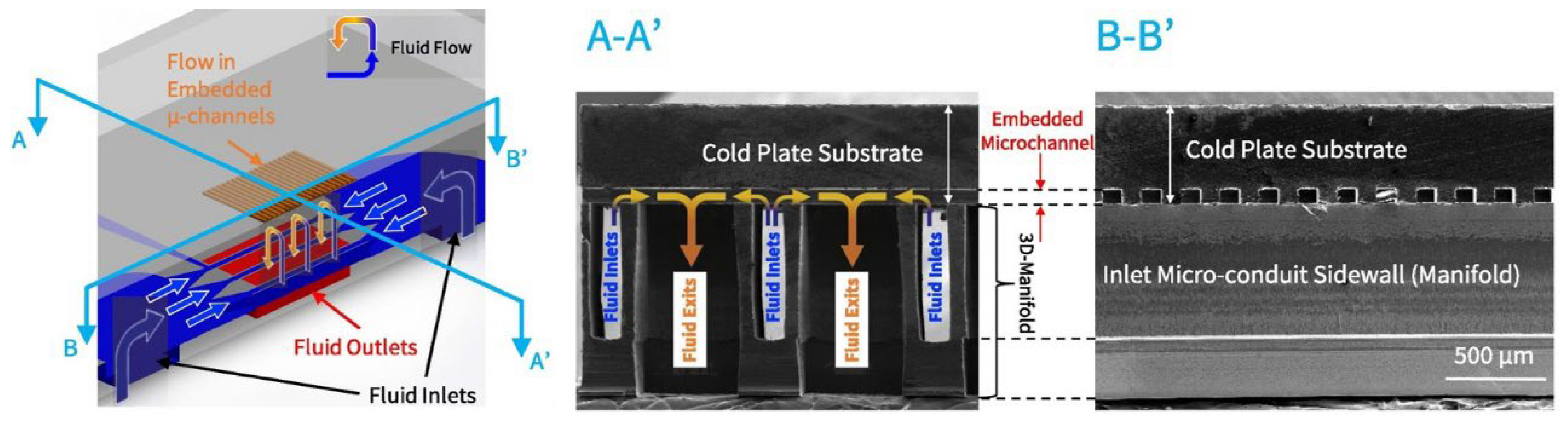
| Jung et al. [82] | EV inverter | Two-phase | R245fa | Embedded microchannels with a 3D manifold | Up to 1000 W/cm2 | N/A |
| Uhlemann et al. [83] | HEV inverter | Single-phase | Ethylene glycol/water mixture | Flat baseplates with ribbon bonded cooling structures | N/A | N/A |
| Jung et al. [84] | HEV inverter | Single-phase | Water | Embedded silicon microchannel baseplate with a 3-D liquid distribution manifold | 250 W/cm2 | Maintain a maximum chip temperature of 90 °C |
| Hou et al. [85] | HEV inverter | Two-phase | R134a | Integrated baseplate with a plate fin structure | 380 W/cm2 | Maintain the chip temperature at about 90 °C |
| Hou et al. [86] | HEV inverter | Two-phase | R1234yf | Integrated baseplate with a plate fin structure | >500 W/cm2 | Maintain the chip temperature below 120 °C |
| Yuki et al. [87] | EV inverter | Two-phase | Distilled water | Baseplate with lotus copper | >500 W/cm2 | N/A |
| Shi et al. [88] | Inverter | Single-phase | Water | Microchannel baseplate with longitudinal vortex generators | N/A | N/A |
| Reference | Target Device | Types of Heat Pipes | Heat Transfer Fluid | Objective |
|---|---|---|---|---|
| Zaghdoudi et al. [122] | Avionics electronic modules | Mini flat heat pipe | Water | Eliminate hot spots and spread the heat dissipated from the components. |
| Cai et al. [123] | High-power electronic devices in avionics systems | PHP | Water | Construct a quick heat transfer path from the electronic devices to the external heat sink. |
| Singh et al. [124] | Automotive dashboard that is heated by radiative heat transfer from the engine | Capillary pumped loop | Acetone | Thermal management of up to 210 W at the source and heat transfer over 1 m. |
| Anderson et al. [125] | Avionics in high-temperature environments | LHP with multiple condenser | N/A | Improve the heat transfer efficiency within electronics enclosure and identify potential sinks to provide continuous heat rejection over the operating envelope of the platform. |
| Reyes et al. [126] | Avionics modules | Vapor chamber | HFE 7100 | Function as a heat spreader. |
| Burban et al. [127] | HEV power electronics | PHP | Acetone, methanol, water, n-pentane | Heat dissipation of the electronics on board vehicle. |
| Ellis et al. [15] | Avionics in high-temperature environments | LHP with two condensers | Methanol | Cool the fuel prior to entering the avionics enclosure, which was determined to be more reliable than cooling the avionics directly. |
| Jones et al. [128] | Avionics modules | Vapor chamber | Water | Reduce the thermal resistance between the avionics component and module heat exchanger. |
| Cai et al. [129] | Avionics modules | LHP combined with PHP | Water | LHP is developed to transport heat from the avionics chassis to the remote heat rejection site. PHP is developed for heat transfer enhancement. |
| Tecchio et al. [130] | Avionics modules | One heat pipe combined with four thermosyphons | Water | Provide passive cooling for electric-powered equipment installed in aircraft. |
| Zilio et al. [131] | Integrated modular avionics in helicopters | LHP | Water | Eliminate hot spots at the blade level. |
| Accorinti et al. [132] | Converter onboard hybrid propulsion aircraft | Capillary pumped loop | Methanol | Ensure a constant operating temperature during the entire mission of the aircraft. |
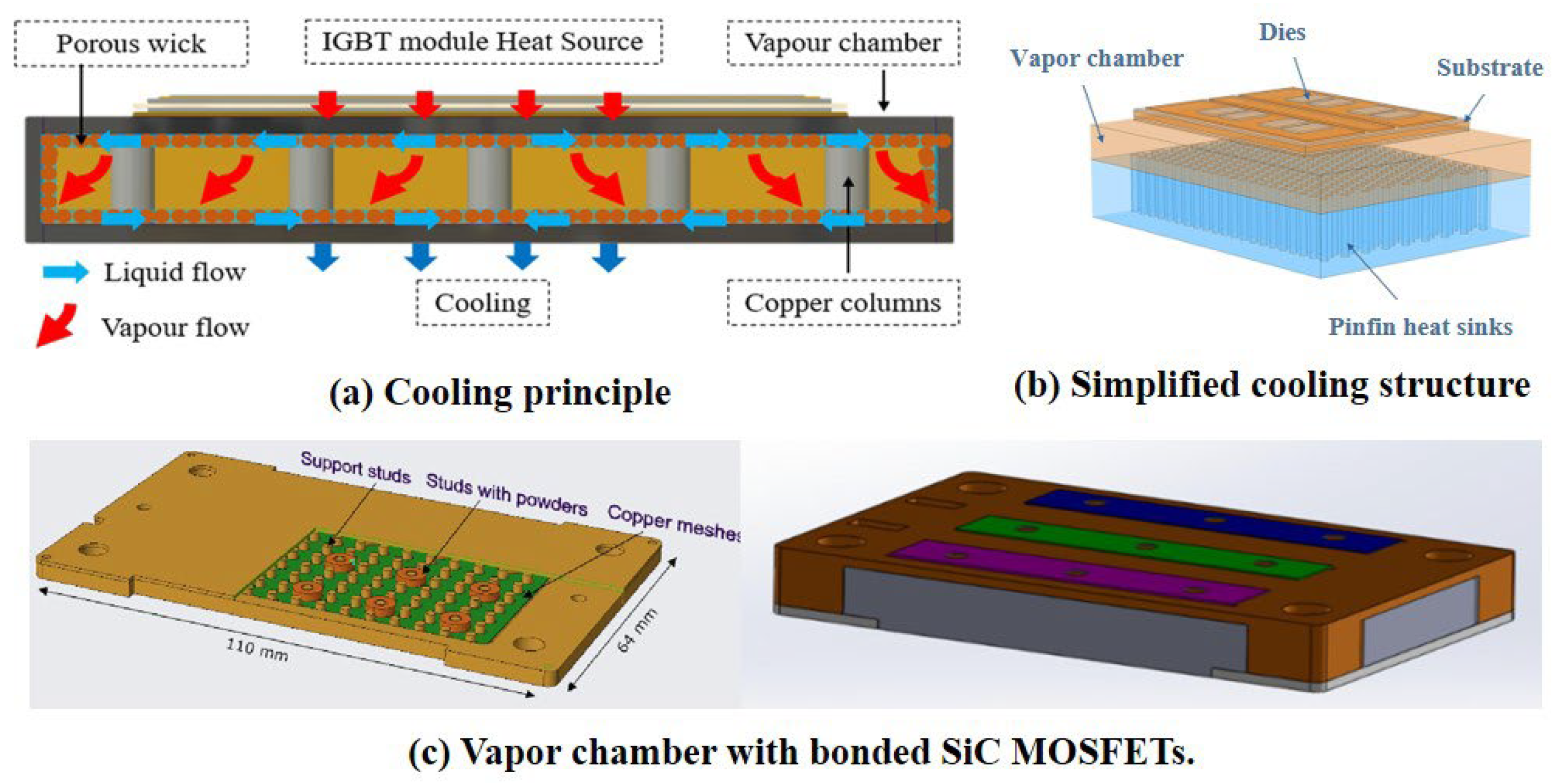
| Chen and Li et al. [133,134,135] | EV inverter | Vapor chamber | Water | Reduce thermal resistance and improve temperature uniformity. |
| Junior et al. [136] | Avionics modules | Flat thermosyphon | Water | Improve the heat removal efficiency from electronic enclosures. |
| Vieira et al. [137] | Avionics modules | Loop thermosyphon | Water | Remove heat from airplane electronic equipment boxes. |
| Pagnoni et al. [138] | Aircraft engine equipment | LHP | Water | Enhance the heat transfer capabilities of currently adopted monophasic solutions. |
| Dreiling et al. [139] | EV inverter | PHP | N/A | Transfer heat to remote heat sinks. |
| Singh et al. [140] | Electronics on board EVs | LHP | Water | Eliminate hot spots and transport heat over longer distances. |
| Thermal Management Technology | Advantages | Disadvantages | |
|---|---|---|---|
| Forced air cooling | Compact, simple layout, and low cost | Low heat transfer efficiency | |
| Indirect contact cold plate cooling | Single-phase | Higher heat transfer efficiency in comparison with forced air cooling, high controllability, and high scalability | Poor temperature uniformity, low stability for temperature control, and the heat dissipation capacity is greatly dependent on the flow rate |
| Two-phase | Much higher heat transfer efficiency, lower flow rates, more uniform surface temperature, and lower pumping power | Complicated loop layout, flow instability, and low technology readiness level | |
| Direct contact baseplate cooling | Higher heat transfer performance, more compact size, and lighter weight (compared with the indirect contact cold plate cooling) | Lower scalability and relatively poorer temperature uniformity (compared with the indirect contact cold plates cooling) | |
| Jet impingement and spray cooling | Much higher heat dissipation capability | Much higher pressure loss and relatively lower controllability | |
| Heat pipes | Excellent heat transfer efficiency and temperature uniformity, no power consumption, longer operational life, high layout flexibility, and low maintenance requirements | Limited heat dissipation capacity | |
| PCMs | High reliability, high scalability, no power consumption, competitive for thermal load with varying magnitudes | Effective operating time is strongly dependent on the mass of PCMs | |
Publisher’s Note: MDPI stays neutral with regard to jurisdictional claims in published maps and institutional affiliations. |
© 2022 by the authors. Licensee MDPI, Basel, Switzerland. This article is an open access article distributed under the terms and conditions of the Creative Commons Attribution (CC BY) license (https://creativecommons.org/licenses/by/4.0/).
Share and Cite
Lv, Y.-G.; Zhang, G.-P.; Wang, Q.-W.; Chu, W.-X. Thermal Management Technologies Used for High Heat Flux Automobiles and Aircraft: A Review. Energies 2022, 15, 8316. https://doi.org/10.3390/en15218316
Lv Y-G, Zhang G-P, Wang Q-W, Chu W-X. Thermal Management Technologies Used for High Heat Flux Automobiles and Aircraft: A Review. Energies. 2022; 15(21):8316. https://doi.org/10.3390/en15218316
Chicago/Turabian StyleLv, Yi-Gao, Gao-Peng Zhang, Qiu-Wang Wang, and Wen-Xiao Chu. 2022. "Thermal Management Technologies Used for High Heat Flux Automobiles and Aircraft: A Review" Energies 15, no. 21: 8316. https://doi.org/10.3390/en15218316
APA StyleLv, Y.-G., Zhang, G.-P., Wang, Q.-W., & Chu, W.-X. (2022). Thermal Management Technologies Used for High Heat Flux Automobiles and Aircraft: A Review. Energies, 15(21), 8316. https://doi.org/10.3390/en15218316