Abstract
In this paper, the impact of an extended surface on the passage of a microchannel using cylindrical ribs with variable sector angles on heat transfer rate is presented using computer simulation. Extended surfaces in the form of cylindrical ribs of varying sector angles in the passage of microchannel in a staggered manner have been designed. The sidewalls of a new kind of microchannel incorporating five distinct ribs with sector angles ranging from 45° to 80° have been analyzed. Ansys Fluent workbench software has been exploited to simulate this novel design of a microchannel heat sink. A three-dimensional heat transfer and fluid flow model of the microchannel heat sink (MCHS) was developed, and the fluid and solid regions were discretized in very fine meshes. All CFD simulations were performed for Reynolds numbers between 100 and 900. Nusselt numbers are varied in the following ranges: 6.93 to 13.87, 6.93 to 14.38, 6.93 to 17.80, 7.15 to 27.86, and 7.20 to 37.38 at sector angles of 45°, 50°, 60°, 70°, and 80°, respectively. It is concluded that the Nusselt number is strongly influenced by the Reynolds number. At an angle of 80°, the maximum friction factor and pumping power requirements were observed. Additionally, a 45° angle has been proven to be the minimal friction factor and pumping power requirement. It is revealed that the THPP has all values larger higher than 1. At angles of 80° and 45°, the maximum and minimum values of THPP have been discovered, respectively. In addition, thermo-hydraulic performance parameters have been evaluated, which are greater than one for all sector angles.
1. Introduction
Electronic gadgets such as, mobile phone, projector, light emitting diode, microprocessor, integrated circuit, etc., generate a large amount of heat when they run continuously for a long time, and they can be damaged if excessive heat is not removed. In order to avoid this damage to these devices, it is necessary to add or remove a fan or a cooling system that will help in removing the excessive heat from these devices. This can be done using different methods such as using fans and cooling systems. Therefore, thermal management of these components/gadgets is a very crucial task in order to increase their life. Micro-channels are one of the key components of electronics and play a significant role in heat removal from these devices. Thermal management is a significant challenge for electronic components because they are often made of materials that conduct heat differently than air, and have very high surface-to-volume ratios. Additionally, micro-channels helps in reduction in the size of electronic equipment because of technological innovation is crucial, as countless transistors are now mounted on a device [1,2,3,4,5]. Congestion at high temperatures and a lack of available space poses serious problems with heat removal. Microchannel heat sink (MCHS) are one of the options offered to solve this problem. MCHSs are employed to remove the intensive heat from electronic components. Heat transfer enhancement using the artificial roughness is very popular in some thermal systems [6,7,8]. The heat dissipation rate from microchannels is accelerated using passive techniques, which include alteration of microchannel passage geometry and increasing the convective heat transfer. The other technique is to use the appropriate heat transfer fluid, which flows inside the microchannel with Reynolds numbers between 100–900 [9].
Since the ground-breaking work of Tuckerman and Pease in 1981 [10], there has been a lot of interest by researchers in the study of microchannel cooling systems. They addressed how the heat transfer coefficient for laminar flow in narrow channels is inversely proportional to the channel width, which makes microscopic channels advantageous [10]. Predictions of heat transmission and entropy had been produced as a result of extensive research into and optimization of heat sink size [11,12]. Microchannels with pins were also perceived in both parallel and staggered forms to study the enhancement in the rate of heat transfer [13]. Geometry modification influences the heat transfer enhancement, which is known as the passive technique. Therefore, heat dissipation characteristics of different shapes such as square, elliptical, round, rectangular, and other shapes were also studied [13,14,15,16]. Meher et al. [17] presented a study on heat transfer and fluid flow characteristics in MCHSs. The results show that it is incorrect to study performance metrics using a Reynolds number, since each coolant has different thermophysical properties, and that the use of nanofluids in MCHS is not feasible because water is more practical and less hazardous. In another study, Vatsa et al. [18] investigated the results of silicon MCHS using a two-sided wedge. According to their findings, a microchannel with a wedge angle of 15° can increase both the Nusselt number and the thermohydraulic efficiency. Chen et al. [19] presented a study on a cross-fin MCHS in which the fluid can rotate to make the fluid itself rotate. It was demonstrated that a cross-ribbed microchannel improved the cooling capacities by 28.6% and 14.3% when compared to rectangle-shaped (MC-R) and horizontal-ribbed microchannels, respectively, although the pressure drop rose to 10.7 and 5.5 times, respectively. Ali et al. [20] analyzed the performance of a MCHS with innovative fins in the shape of trefoil. Numerical analysis was performed comparing three different configurations of trefoil ribs with smooth channels with no fins on the walls. The three trefoil shape configurations consisted of: (1) trefoil fins on the side wall, (2) trefoil fins on the base wall and (3) trefoil fins on the entire wall. It was found that all the configurations with trefoil ribs had higher Nusselt numbers, but at a penalty of higher fluid friction factors. The configuration with trefoil fins on side walls showed the highest thermal improvement factor of 1.6. Yadav et al. [21] employed a rectangular microchannel with cylinder-shaped micro fins in the passage of the microchannel. Three distinct configurations, including upstream, downstream, and fully finned, have been simulated numerically. As a result, the microchannel structure with upstream fins turned out to have a higher heat transfer efficiency than the one with downstream fins.
Apart from the numerical work, researchers have also demonstrated the experiments in order to validate the theoretical models. Therefore, Jia et al. [22] conducted experiments in an oval-shaped microchannel to study different heat transfer and fluid flow characteristics in a laminar flow with a Reynolds numbers between 157 and 668. It was reported that the microchannel with oval-shaped pin fins was more effective than conventional simple microchannels. Isaev et al. [23,24] experimentally evaluated the anomalous enhancement of the separated flow and heat transfer phenomenon in slanted oval dimples. In addition, Isaev et al. [25] studied turbulent flow around longitudinal plate fragments in terms of convective heat transfer enhancement. Eneren et al. [26] presented a comprehensive review of various experimental studies and addressed different nanofluid parameters such as thermal conductivity, stability, and particle–surface interactions such as erosion, abrasion, corrosion, and particle clumping that could hinder the heat transfer rate in microchannels. Huang et al. [27] carried out an experimental analysis of heat transfer and fluid flow properties in microchannel heat exchangers with fan-shaped cavities. To compare the advantages of fan-shaped cavities, conventional microchannel heat exchangers were also tested in similar conditions. The results show that fan-shaped microchannel heat exchangers can perform better than straight microchannel heat exchangers in terms of heat transfer and pressure drop. Chai et al. [28] carried out an experimental study on MCHS with an alternate expansion–constriction cross-section. Heat transfer and fluid friction properties were assessed relatively to the effects of the alternate expansion–constriction cross section.
Passive techniques for performance improvement of MCHS are becoming increasingly important due to their ease of use. These techniques include the geometry modification in passages such as trapezoidal grooves [29], V ribs [2], hemisphere cavities [30], dimple ribs [31,32], tree-like branching with dimples [33] and cavities on side walls [34]. These designs achieve larger Nusselt numbers and substantially smaller pressure drops. In addition, the combination of more than one geometry modification is also explored as a possibility to enhance the heat transfer rate. Interlinked double-layer matrix structures and complex double-layer structures for microchannels were studied further. The numerical findings demonstrate that the matrix’s periodic slot sub-channel had a sizable impact on heat transfer and fluid flow properties [35]. In another study, grooves for wavy microchannel heat exchangers were investigated. The optimal design improved the heat transfer and friction factor by 1.55% and 3.00% when compared to the referent design [36]. Thermal performance in MCHSs of various sizes of micro-inserts were studied. Micro-inserts had the best heat transfer performance, with an improvement of 1–9% and 14.5% increase in pressure drop in the range of Reynolds numbers between 56 and 2242 [37]. In the literature, there is a lack of parametric studies on the micro-channel geometric design, especially extended surfaces having circular ribs. Various modifications are widely investigated, but parametric studies on that geometry are not available. This paper seeks to bring to light the fact that microchannel and cylindrical ribs are not as well-known within the field of engineering as they should be. Specifically, it is intended to provide information on how these two types of structures can be used together to provide an improved design for a certain application. Cylindrical ribs are commonly used to increase the strength of a material, as well as to provide added rigidity to a structure. However, there is a lack of research on how these ribs can be used in microchannel applications to enhance heat transfer. In this work, we will describe how cylindrical ribs can be applied to enhance the heat transfer of microchannels. From the previous literature review, it can be concluded that different geometrical modifications have already been investigated; however, parametric studies on a given geometry are not yet widely available.
This work presents the effect of circular ribs of same diameter and pitch at the side walls of microchannel passage in staggered manner on the performance of microchannel using computer simulation. The geometry of the ribs has been governed by varying sector angles from 45° to 80°. The goal of the work is to analyze the performance parameters due to these sidewall modification with a Reynolds number varying from 100 to 900. The outcomes have then been compared with those of a simple microchannel to offer theoretical benchmarks for a wide range of heat sink applications.
2. Computational Model of MCHS
2.1. Design and Computational Model
The computation domain of the MCHS has been the computational MCHS, along with domain of water, was created in the design modular of Ansys Fluent. The domain is three-dimensional considering the following assumptions, i.e., non-isothermal at steady state, and uses a single-phase fluid (water). The microchannel consists of 50 channels with rectangular cross-section, which require substantial computing resources and a prohibitively long time to complete. Therefore, a single channel of the MCHS represents the computational domain that has been considered for simulation in all cases. The single channel has been shown in Figure 1 with the following dimensions, i.e., a length of 10 mm, a height of 0.35 mm and a width 0.2 mm. The ribs on the passage wall are designed with sector angles varying from 45° to 80°, while rib pitch is set fixed at 0.4 mm and rib radius is set fixed as 0.025 mm. The top view of the cylindrical ribs on the passage wall are shown in Figure 2.
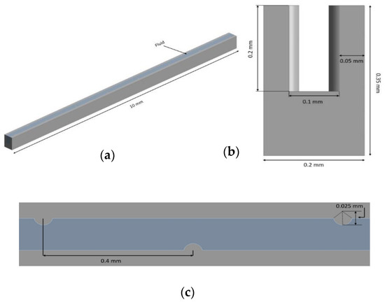
Figure 1.
Single microchannel’s 3D computational domain having cylindrical protrusion ribs in a staggered manner (a) isometric view, (b) front view, and (c) top view.
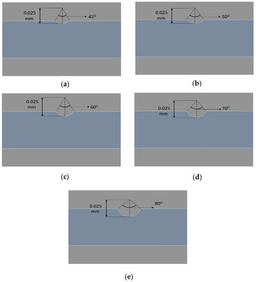
Figure 2.
Cylindrical rib on the passage wall of the microchannel (top view) of angle (a) 45°, (b) 50°, (c) 60°, (d) 70°, and (e) 80°.
2.2. Numerical Models
In this subsection, numerical models have been presented and discussed. Governing equations of conservation of mass, conservation of momentum and energy equations of heat transfer fluid and MCHS have been exploited and presented below. The following assumptions have been made in order to solve these equations. The flow is considered as laminar in steady state conditions. Since water is employed as a heat transfer fluid, therefore, it is considered as incompressible fluid.
The conservation of mass or equation of continuity:
The conservation of momentum in x, y and z directions are given below as Equations (2)–(4), respectively.
The energy equation for heat transfer fluid:
The energy equation for MCHS (silicon):
2.3. Properties of MCHS and Heat Transfer Fluid
In the present study, two computational domains, namely; the domains of MCHS and fluid have been employed. The thermophysical properties of MCHS (silicon material) and fluid (water) have been presented in Table 1 and Table 2, respectively.

Table 1.
The thermophysical properties of water (T = 300 K).
Table 2.
The thermophysical properties of silicon.
2.4. Boundary Conditions and the Computational Process
For all simulations, the design module of Ansys Workbench is used to build a computation domain for a single microchannel and fluid domain. As seen in Figure 3, a multizone-structured fine mesh has been created. To demonstrate mesh independence, several simulations have been run for grid sensitivity by changing the numbers of elements and nodes in the ranges of 115,725 to 1,376,206 and 154,541 to 154,854, respectively. The values of the friction factor and the corresponding error for two consecutive friction factor numbers are shown in Table 3 along with the number of nodes and elements. It is evident that when the number of nodes increases from 154,541 to 1,208,153, the error decreases from 6.15 to 0.64 percent. As a result of the fact that a further increase in node count does not significantly alter the friction factor, therefore, 1,208,153 nodes are taken into account for the remainder of the simulation. An iterative technique of the solution process used the SIMPLE method to account for velocity–pressure coupling. To obtain solution convergence, an iterative solution is employed with a convergence criterion of 1 × 10⁻⁹ for energy and 1 × 10⁻⁶ for the momentum and velocity component. According to the chosen Reynolds number, which can be between 100 and 900, the fluid’s inlet velocity is provided. The outlet of the flow was considered as out flow in the atmospheric; therefore, zero gauge pressure is provided at the outlet. Symmetric boundary conditions are provided to sidewalls, whereas a constant heat flux of 1.0 106 W/m2 is introduced to the bottom of MCHS.
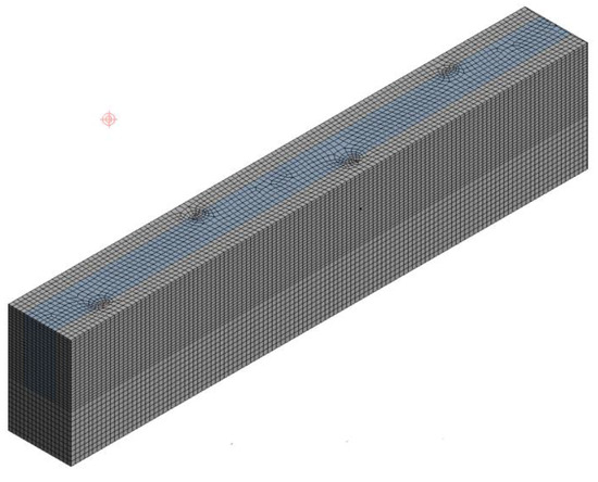
Figure 3.
The mesh for the microchannel and fluid zone.
Table 3.
Mesh independence test.
2.5. Data Reduction
Numerical solutions in the flow domain and microchannel domain are used to obtain copious amounts of data. To display the results in terms of analytical parameters and performance parameters, data reduction was done. These parameters are given below:
Reynolds number:
Dh is hydraulic diameter is calculated as given below:
The conjugated area average temperature is:
The mass-weighted average temperature of heat transfer fluid:
The average Nusselt number (:
where, average convective heat transfer coefficient is:
The Average friction factor is:
2.6. Model Validation
Well-known experimental results acquired by Chai et al. [28] were used to verify the results by using a numerical model. Numerical results of smooth MCHS (without geometrical modifications) have been compared with the experimental results. Figure 4 depicts the comparison of the numerically acquired Nusselt numbers and friction factors of the MCHS with experimental values of friction factors and Nusselt number operating under similar conditions. The numerical findings are in line with the experimental findings, proving the validity of the mathematical model employed in this study. This suggests that the present numerical results are trustworthy and that the subsequent simulations can be carried out using this numerical approach.
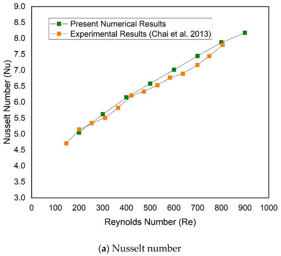
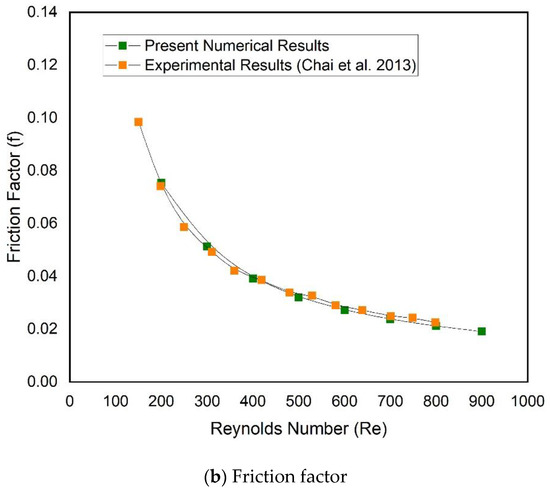
Figure 4.
Comparison between numerical experimental results data for (a) Nusselt numbers and (b) friction factors [28].
3. Results and Discussion
Numerical simulations of the MCHS with cylindrical protrusions in a staggered manner on passage of the microchannel are performed for Re = 100–900. A heat flux of 1.0 × 10⁶ W/m2 is uniformly applied to the microchannel’s base. The distribution of pressure drops and velocity within the sphere of flow has been shown and explained to understand the fluid flow characteristics. Additionally, the distribution of temperature in the microchannel and fluid domain has been discussed to analyze the heat dissipation rate.
3.1. Velocity Contour
The velocity contour of flow due to different angles has been presented and compared at two values of Reynolds numbers (100 and 900) as shown in Figure 5. It is evident that for a Reynolds number of 100, the velocity increases steadily with an increasing angle from 45° to 80°. However, for a Reynolds number of 900, the velocity reduces somewhat with an increasing angle from 45° to 70° before rising dramatically at 80°. In addition, a significant reduction in velocities is observed when Reynolds changes from 100 to 900. This occurs as a result of the creation of turbulence and formation of eddies around the ribs and an increase in the total convective surface area of MCHS with an increasing angle. Greater heat dissipation to the water is provided due to greater convective surface areas.
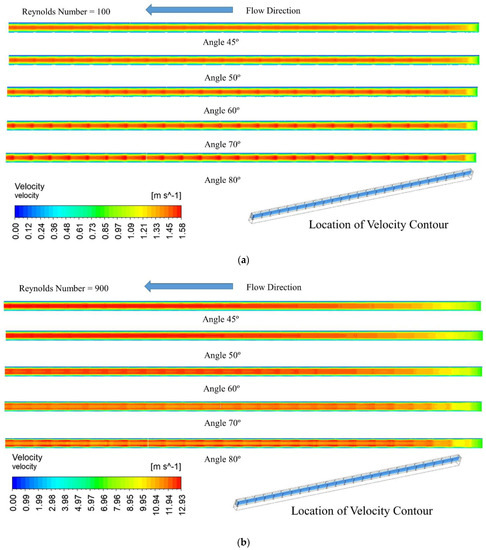
Figure 5.
Distribution of velocity in microchannel’s fluid domain at (a) Re = 100 and (b) Re = 900 at various angles.
3.2. Pressure Drop Contour
Figure 6 shows the pressure distribution in the fluid domain of the MCHS for Reynolds numbers between 100 and 900. The pressure decrease in the flow field along the length of MCHS as shown in the Figure. The case of angle 80° results in the most pressure drop, whereas angle 45° results in the lowest pressure drop at Reynolds number of 100. Similar trends in pressure loss caused by different angles can be seen for Reynolds number of 900. Additionally, there is a significant change in pressure drop are observed as a result of altering the angle of protrusion ribs. The pressure drop at a particular angle and the Reynolds number of 900 is significantly greater than the pressure loss at a similar angle for the Reynolds number of 100, as seen by these contours. At increasing Reynolds numbers, the flow is found to be constrained by the water’s viscosity.
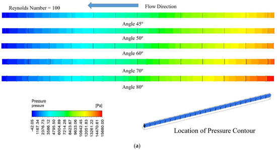
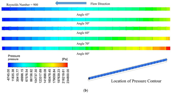
Figure 6.
Pressure distribution in the fluid domain at (a) Re = 100 and (b) Re = 900.
3.3. Temperature Contour
The temperature contour of the fluid and MCHS has been shown at the mid-plane of fluid and MCHS domain as shown in Figure 7 for various angles and two distinct Reynolds numbers (100 and 900). The highest temperature is displayed at the base of the microchannel wall where electronic chips are mounted. Fluid temperature increases gradually along the flow in the MCHS and attend maximum at the exit of MCHS. Similar observations have been found for all angles at both Reynolds numbers. However, the increase rate of the temperature decreased slightly when the angle increased from 45° to 80°. This is happened at both Reynolds numbers. The higher rate of heat dissipation is indicated as a result of relatively lower temperatures. The maximum temperature also drops precipitously once the Re varied from 100 to 900. The viscous laminar layer deteriorated at higher Reynolds numbers, which draws out more heat in more efficient ways.
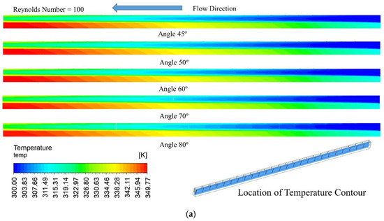
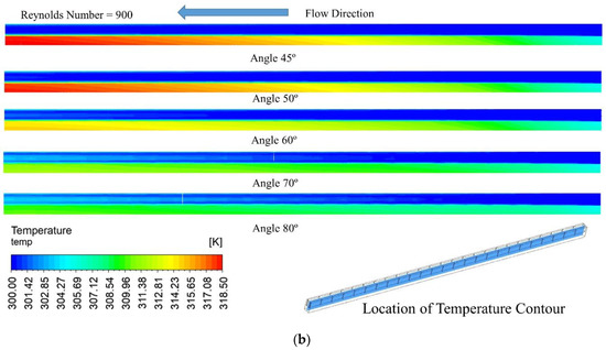
Figure 7.
Temperature profile at the mid plane of the microchannel and fluid domain at (a) Re = 100 and (b) Re = 900.
Figure 8 depicts the temperature distribution at the microchannel base for different angles and two extreme Reynolds numbers, that is 100 and 900. The temperature variation throughout the microchannel’s base is roughly equivalent; however, the maximum temperature slightly drops as the angle increases from 45° to 80°, when the Reynolds numbers are 100 and 900, respectively. This hardly noticeable shift in maximum temperature suggests that the significant heat loss should be seen at a somewhat higher angle. However, when the Re varied from 100 to 900, the maximum temperature at the microchannel base decreases dramatically from 349.8 K to 318.5 K and from 348.4 K to 310.2 K, respectively, for angles of 45° and 80°. This appreciable drop in maximum temperature suggests that altering the Reynolds number has a major impact on how heat is exchanged between the microchannel and fluid.
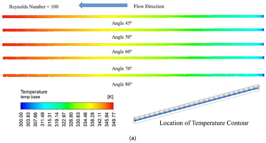
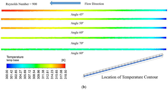
Figure 8.
Variation of temperature at the base of the interface between fluid and MCHS at (a) Re = 100 and (b) Re = 900.
3.4. Performance of the MCHS
As previously stated, a thorough analysis of the MCHS is required. It has been demonstrated and investigated how different MCHS properties affect heat transmission and fluid flow. The responses of Nusselt number, the temperature of the base wall, friction factor, and pumping power are plotted for different Reynolds numbers to numerically assess the functionality of the MCHS with various angles of circular protrusions ribs on the passage walls of the microchannel in a staggered manner.
The Nusselt number of an MCHS varies with Reynolds numbers for various angles, as seen in Figure 9. The trend of Nusselt numbers is shown to be gradually growing when compared to them for various angles. However, the maximum Nusselt number values are discovered for an angle of 80° for all Reynolds number values, while the lowest values are found for an angle of 45°. The following ranges of Nusselt numbers from 6.93 to 13.87, 6.93 to 14.38, 6.93 to 17.80, 7.15 to 27.86, and 7.20 to 37.38 have been found at an angle of 45°, 50°,60°, 70°, and 80°, respectively. The highest Nusselt number in the case of angle 80° is found because the heat transfer area is increased and ribs contribute to higher turbulence, which helps to suppress the sublaminar layer. The temperature contour outlined in the preceding subsection can be used to explain this.
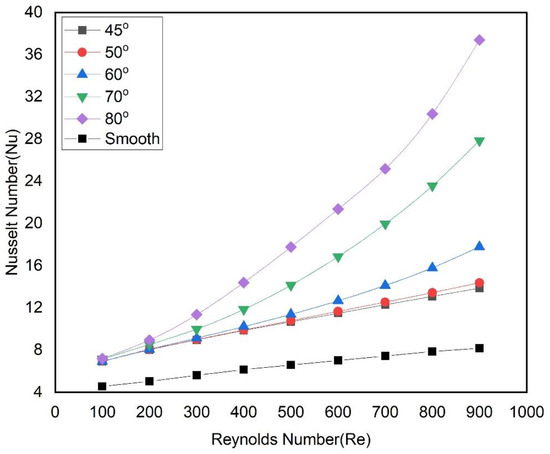
Figure 9.
Nusselt numbers and Reynolds numbers in relation to various angles.
The base temperature of the passage is depicted in Figure 10 at various angles as a function of the Reynolds number to explain the behavior of the heat dissipation rate. It has been shown that at all angles, the base temperature falls as the Reynolds number rises. At low Reynolds numbers, there is a quick drop in temperature, while higher Reynolds numbers result as somewhat asymptotic for all angles. In the case of an 80° angle, the lowest value of temperature is found, while in the case of 45°, the highest value of the base temperatures is found for all Reynolds numbers. The low temperature at the base of the passage indicates that the MCHS dissipates heat at the fastest possible rate for passages with an angle of 80°.
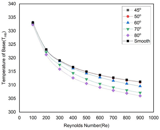
Figure 10.
Variation of temperature at the fluid and MCHS interface base wall with Reynolds numbers for different angles.
Figure 11 shows the variation of the Nusselt number with the convective heat transfer area of the passage at various Reynolds number areas. It is seen that the Nusselt number increases with the increase of heat transfer areas at all Reynolds number. However, the most important observations are the rate of increment of Nusselt number with convective heat transfer areas. When the area increased corresponding to ribs sector angles from 45° to 60°, the Nusselt number does not increase significantly. Thereafter, there is a significant increase in Nusselt number when area correspond to ribs sector angles increase from 60° to 80°. This shows that at higher rib sector angles, turbulence as well as the convective heat transfer area have a significant impact on the Nusselt number.
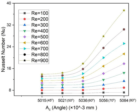
Figure 11.
Dependence between Nusselt number and heat transfer area for different Reynolds numbers.
Figure 12 illustrates the variation of the friction factor of a heat transfer fluid in an MCHS as a function of the Reynolds number at various angles. For all angles, the friction factor reduces as the Reynolds increases. It has been found that the declination rate in the friction factor is faster at low Reynolds. For all Reynolds numbers, the maximum friction factor is observed at an 80° angle and the lowest at a 45° angle. It is because the MCHS passage with an 80° angle restricts and disturbs the flow significantly in comparison to other angles, thereby leading to a higher heat dissipation rate. Although, a higher friction factor is undesirable in the context of high pumping power requirements. In this regard, fluid pumping power requirements have been evaluated in MCHS passage with various protrusion rib angles concerning Reynolds numbers (Figure 13). It can be seen that pumping power increases with an increase in the Reynolds for all angles. The rate of increment of pumping power is highest in the case of an 80° angle, while the angle 45° has the lowest rate of increment. This trend confirms the behavior of the friction factor due to various angles of ribs in the passage of MCHS.
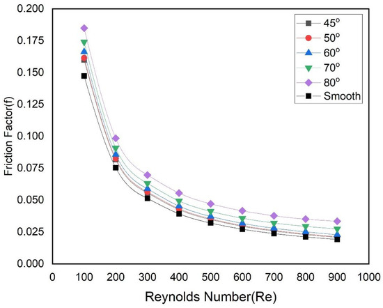
Figure 12.
Friction factor varies with Reynolds number at various angles.
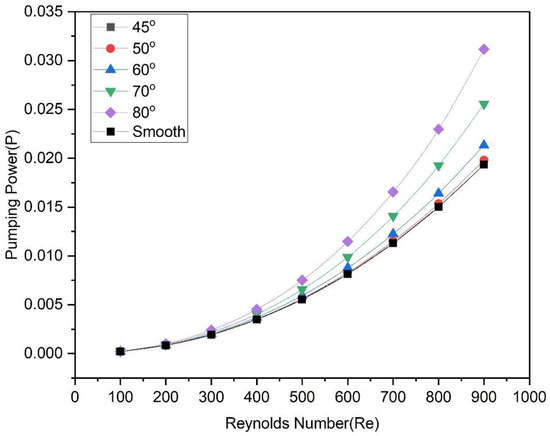
Figure 13.
Pumping power varies with Reynolds number for various angles.
Figure 14 shows the dependence between friction factor and heat transfer area for different rib sector angles in the passage and for different Reynolds numbers. It is seen that the friction factor increases with an increase in heat transfer area at all Reynolds numbers. Similar observations have been found in the case of the Nusselt number. The heat transfer area causes a slight increase in the Nusselt number, when the rib sector angle varies from 45° to 60°. Considerable increase is observed in the friction factor with the heat transfer area when the rib sector angles increase from 60° to 80°.
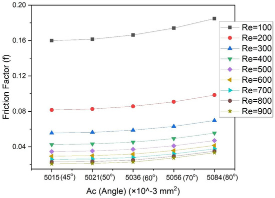
Figure 14.
Friction factor variation with heat transfer area at various Reynolds numbers.
In the previous discussion, it is seen that the passage with rib sector angle of 80° exhibits maximum friction factors and Nusselt numbers. In this regard, the dependance between Nusselt numbers and pumping power is plotted in Figure 15. For various ribs sector angles, it is seen that the Nusselt number increases with the pumping power regardless of the sector angle. However, the rate of increment in the Nusselt number with pumping power is highest at the angle of 80°. Conversely, the rate of increment of the Nusselt numbers with the pumping power is lowest when the angle is 45°. Additionally, for a given pumping power requirement, the highest Nusselt number is observed at the angle of 80°.
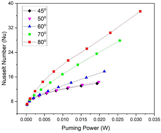
Figure 15.
Dependence between Nusselt number and pumping power for different angles.
The heat transfer and fluid friction properties due to cylindrical protrusions in a staggered manner on the passage of the microchannel have been analyzed. Both the Nusselt and the friction are found to be superior at an angle of 80°. However, these values do not decide the best configuration because superior values of Nusselt numbers are preferred, whereas the highest value of friction values are undesirable. The best configuration yields higher values of Nusselt number, which leads to higher thermal performance, and lower values of friction factor, which lead to lower pumping power (i.e., hydraulic performance). It is important to evaluate both the thermal and hydraulic performance at the same time, which affects the overall performance, and to separate the impact of the angle on the friction factor and the heat transfer. As a result, the influence of angle on the overall performance of the MCHS has been demonstrated using the thermal-hydraulic performance parameter (THPP). THPP is more crucial than all other individual performance parameters for effective design. Additionally, values of THPP more than unity shows the effective configuration. THHP is calculated as given below.
The values of THPP have been evaluated for different angles as an attribute of the Reynolds number, as shown in Figure 16. The values of THPP rise for all angles as the Reynolds number rises. For angles 45° to 60°, the plots rise steadily, while for angles 45° to 60°, it rises significantly. The ranges of THPP correspond to angles of 45°, 50°, 60°, 70°, and 80° are found as 1.47 to 1.65, 1.47 to 1.70, 1.45 to 2.05, 1.48 to 3.02, and 1.46 to 3.79, respectively. It has been noticed that values of THPP are higher than 1, and maximum values have been found at an angle of 80°. Therefore, cylindrical protrusions in a staggered manner on passage of microchannel have an advantage over a smooth passage.
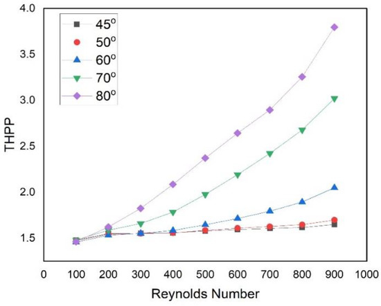
Figure 16.
Dependence between THPP and the Reynolds number.
4. Conclusions
Cylindrical protrusions in a staggered manner on the passage of the microchannel having angles 45° and 80° have been taken into account in this new design of the microchannel. The heat transfer and fluid movement in the microchannel are modeled using computational fluid dynamics in Ansys Fluent, with water serving as the heat transfer fluid. The numerical results that were obtained led to the following conclusions.
- There is an increase in heat transfer and fluid friction when the rib sector angles change from 45° to 80°. However, it is evident that the convective heat transfer area plays an important role in the Nusselt number enhancement when the angle changes from 45° to 60°. However, significant enhancement in Nusselt number is observed due to flow turbulence when angle changes from 60° to 80°.
- The Nusselt number is greatly influenced by the Reynolds number. Nusselt numbers are varied in the following ranges 6.93 to 13.87, 6.93 to 14.38, 6.93 to 17.80, 7.15 to 27.86, and 7.20 to 37.38 at an angle of 45°, 50°, 60°, 70°, and 80°, respectively.
- The maximum friction factor and pumping power requirement have been found at an angle of 80° while the lowest friction factor and pumping power are found at an angle of 45°.
- The maximum heat transfer enhancement is 4.57 in the case of rib sector angle of 80°. Similarly, the maximum increase of friction factor is 1.52 when the rib sector angle is 80°.
- The maximum and minimum values of THPP are found at rib sector angles of 80° and 45°, respectively. In addition to this, all values of THPP are found to be more than unity.
- Following ranges of THPP values are found as 1.47 to 1.65, 1.47 to 1.70, 1.45 to 2.05, 1.48 to 3.02, and 1.46 to 3.79 for corresponding angles of 45°, 50°, 60°, 70°, and 80°, respectively.
Author Contributions
Conceptualization, A.P.D., T.A. and M.I.H.S.; methodology, T.A. and P.B.; software, A.P.D., T.A. and M.K.; validation, T.A., N.K.G., P.B. and A.S.Y.; formal analysis, T.A. and N.K.G.; investigation, A.P.D., T.A. and M.A.A.; resources, T.A. and P.B.; data curation, A.P.D., T.A. and M.I.H.S. and M.K.; writing—original draft preparation, A.P.D., T.A.; writing—review and editing, A.P.D., T.A., M.I.H.S. and A.S.Y.; visualization, T.A., N.K.G. and P.B.; supervision, T.A. and N.K.G.; project administration, T.A. and A.S.Y.; funding acquisition, P.B. All authors have read and agreed to the published version of the manuscript.
Funding
This research received no external funding.
Data Availability Statement
Data available on request.
Conflicts of Interest
The authors declare no conflict of interest.
Nomenclature
| Convective heat transfer area (m2) | Ac |
| Base area of channel (m2) | Aq |
| Specific heat (J/kg·K) | Cp |
| Hydraulic diameter (mm) | Dh |
| Young module (GPa) | E |
| Friction factor | f |
| Length (mm) | L |
| Convective eat transfer coefficient (W/m2∙K) | h |
| Height of passage (mm) | H |
| Thermal conductivity (W/m∙K) | K |
| Nusselt number | Nu |
| Pressure (Pa) | P |
| Pressure drop (Pa) | ∆p |
| Pumping power (W) | P |
| Heat flux (W/m2) | Q |
| Reynolds Number | Re |
| Temperature (K) | T |
| Velocity (m/s) | U |
| Width of microchannel (m) | W |
| Greek letters | |
| Poisson’s ratio | α |
| Thermal expansion [1/K] | ℘ |
| Dynamic Viscosity (Pa∙s) | μ |
| THPP | η |
| Density (kg/m3) | ρ |
| Subscripts | |
| Microchannel base | mc |
| Fluid (coolant) | f |
| Conventional | s |
References
- Liu, Z.; Qin, S.; Chen, X.; Chen, D.; Wang, F. PDMS-PDMS micro channels filled with phase-change material for chip cooling. Micromachines 2018, 9, 165. [Google Scholar] [CrossRef]
- Wang, R.; Wang, J.; Yuan, W. Analysis and optimization of a MCHS with V-ribs using nanofluids for micro solar cells. Micromachines 2019, 10, 620. [Google Scholar] [CrossRef] [PubMed]
- Duan, Z.; Ma, H.; He, B.; Su, L.; Zhang, X. Pressure drop of microchannel plate fin heat sinks. Micromachines 2019, 10, 80. [Google Scholar] [CrossRef]
- Memon, S.A.; Cheema, T.A.; Kim, G.M.; Park, C.W. Hydrothermal investigation of a MCHS using secondary flows in trapezoidal and parallel orientations. Energies 2020, 13, 5616. [Google Scholar] [CrossRef]
- Kumar, A.; Verma, S.K. Design and development of e-smart robotics-based underground solid waste storage and transportation system. J. Clean. Prod. 2022, 343, 130987. [Google Scholar] [CrossRef]
- Kumar, R.; Kumar Verma, S. Performance estimation of Triangular Solar air heater roughened absorber surface: An experimental and simulation modeling. Sustain. Energy Technol. Assess. 2022, 52, 13–15. [Google Scholar] [CrossRef]
- Kumar, R.; Kumar Verma, S. Review based on the absorber plate coating for solar air heater applications. IOP Conf. Ser. Mater. Sci. Eng. 2021, 1116, 012053. [Google Scholar] [CrossRef]
- Kumar, R.; Kumar Verma, S. Numerical investigation of performance analysis of Triangular Solar air heater using Computational Fluid Dynamics (CFD). IOP Conf. Ser. Mater. Sci. Eng. 2021, 1116, 012047. [Google Scholar] [CrossRef]
- Derakhshanpour, K.; Kamali, R.; Eslami, M. Effect of rib shape and fillet radius on thermal-hydrodynamic performance of MCHSs: A CFD study. Int. Commun. Heat Mass Transf. 2020, 119, 104928. [Google Scholar] [CrossRef]
- Tuckerman, D.B.; Pease, R.F.W. High-Performance Heat Sinking for VLSI. IEEE Electron Device Lett. 1981, 2, 126–129. [Google Scholar]
- Teertstra, P.; Yovanovich, M.M.; Culham, J.R. Analytical Forced Convection Modeling of Plate Fin Heat Sinks. J. Electron. Manuf. 2000, 10, 253–261. [Google Scholar] [CrossRef]
- Copeland, D. Optimization of parallel plate heatsinks for forced convection. In Proceedings of the Sixteenth Annual IEEE Semiconductor Thermal Measurement and Management Symposium, San Jose, CA, USA, 23 March 2000. [Google Scholar]
- Pandey, A.K.; Reji Kumar, R.; Kalidasan, B.; Laghari, I.A.; Samykano, M.; Kothari, R.; Abusorrah, A.M.; Sharma, K.; Tyagi, V.V. Utilization of solar energy for wastewater treatment: Challenges and progressive research trends. J. Environ. Manag. 2021, 297, 113300. [Google Scholar] [CrossRef] [PubMed]
- Al-Asadi, M.T.; Alkasmoul, F.S.; Wilson, M.C.T. Benefits of spanwise gaps in cylindrical vortex generators for conjugate heat transfer enhancement in micro-channels. Appl. Therm. Eng. 2018, 130, 571–586. [Google Scholar] [CrossRef]
- Kumar, N.; Gupta, S.K.; Sharma, V.K. Application of phase change material for thermal energy storage: An overview of recent advances. Mater. Today Proc. 2021, 44, 368–375. [Google Scholar] [CrossRef]
- Jacobs, E.N.; Ward, K.E.; Pinkerton, R.M. The Characteristics of 78 Related Airfoil Sections From Tests in the Variable-Density Wind Tunnel; US Government Printing Office: Washington, DC, USA, 1933.
- Sadiq Al-Baghdadi, M.A.R.; Noor, Z.M.H.; Zeiny, A.; Burns, A.; Wen, D. CFD analysis of a nanofluid-based MCHS. Therm. Sci. Eng. Prog. 2020, 20, 100685. [Google Scholar] [CrossRef]
- Vatsa, A.; Alam, T.; Siddiqui, M.I.H.; Ali, M.A.; Dobrotă, D. Performance of MCHS Made of Silicon Material with the Two-Sided Wedge. Materials 2022, 15, 4740. [Google Scholar] [CrossRef]
- Chen, H.; Chen, C.; Zhou, Y.; Yang, C.; Song, G.; Hou, F.; Jiao, B.; Liu, R. Evaluation and Optimization of a Cross-Rib Micro-Channel Heat Sink. Micromachines 2022, 13, 132. [Google Scholar] [CrossRef]
- Ali, S.; Ahmad, F.; Akhtar, K.; Habib, N.; Aamir, M.; Giasin, K.; Vafadar, A.; Pimenov, D.Y. Numerical investigation of MCHS with trefoil shape ribs. Energies 2021, 14, 6764. [Google Scholar] [CrossRef]
- Wang, G.; Feng, L.; Altanji, M.; Sharma, K.; Nisar, K.S.; Khorasani, S. Proposing novel “L” shaped fin to boost the melting performance of a vertical PCM enclosure. Case Stud. Therm. Eng. 2021, 28, 101465. [Google Scholar] [CrossRef]
- Jia, Y.; Huang, J.; Wang, J.; Li, H. Heat transfer and fluid flow characteristics of microchannel with oval-shaped micro pin fins. Entropy 2021, 23, 1482. [Google Scholar] [CrossRef]
- Isaev, S.A.; Baranov, P.A.; Leontiev, A.I.; Popov, I.A. Intensification of a Laminar Flow in a Narrow Microchannel with Single-Row Inclined Oval-Trench Dimples. Tech. Phys. Lett. 2018, 44, 398–400. [Google Scholar] [CrossRef]
- Isaev, S.A.; Guvernyuk, S.V.; Mikheev, N.I.; Popov, I.A.; Nikushchenko, D.V. Numerical and experimental study of abnormal enhancement of separated turbulent flow and heat transfer in inclined oval-trench dimples on the plate and on the narrow channel wall. J. Phys. Conf. Ser. 2021, 2039, 012009. [Google Scholar] [CrossRef]
- Isaev, S.A.; Leontiev, A.I.; Nikushchenko, D.V.; Kong, D.; Chung, K.M.; Sudakov, A.G. Vortex heat transfer enhancement by energy-efficient structured plates with zigzag grooves for micro- and macro-scale energy and electronic devices. J. Phys. Conf. Ser. 2022, 2150, 012004. [Google Scholar] [CrossRef]
- Eneren, P.; Aksoy, Y.T.; Vetrano, M.R. Experiments on Single-Phase Nanofluid Heat Transfer Mechanisms in MCHSs: A Review. Energies 2022, 15, 2525. [Google Scholar] [CrossRef]
- Huang, B.; Li, H.; Xu, T. Experimental investigation of the flow and heat transfer characteristics in microchannel heat exchangers with reentrant cavities. Micromachines 2020, 11, 403. [Google Scholar] [CrossRef]
- Chai, L.; Xia, G.; Wang, L.; Zhou, M.; Cui, Z. Heat transfer enhancement in MCHSs with periodic expansion-constriction cross-sections. Int. J. Heat Mass Transf. 2013, 62, 741–751. [Google Scholar] [CrossRef]
- Wang, R.; Wang, W.; Wang, J.; Zhu, Z. Analysis and optimization of trapezoidal grooved MCHS using nanofluids in a micro solar cell. Entropy 2018, 20, 9. [Google Scholar] [CrossRef]
- Schukin, A.V.; Kozlov, A.P.; Agachev, R.S. The American society of mechanical engineers study and application of hemispheric cavities for surface heat transfer augmentation. In Proceedings of the ASME 1995 International Gas Turbine and Aeroengine Congress and Exposition, Houston, TX, USA, 5–8 June 1995. [Google Scholar]
- Mahmood, G.I.; Sabbagh, M.Z.; Ligrani, P.M. Heat Transfer in a Channel with Dimples and Protrusions on Opposite Walls. J. Thermophys. Heat Transf. 2001, 15, 275–283. [Google Scholar] [CrossRef]
- Parashar, A.K.; Gupta, A. Investigation of the effect of bagasse ash, hooked steel fibers and glass fibers on the mechanical properties of concrete. Mater. Today Proc. 2001, 44, 801–807. [Google Scholar] [CrossRef]
- Shui, L.; Sun, J.; Gao, F.; Zhang, C. Flow and heat transfer in the tree-like branching microchannel with/without dimples. Entropy 2018, 20, 379. [Google Scholar] [CrossRef]
- Li, H.; Li, Y.; Huang, B.; Xu, T. Numerical investigation on the optimum thermal design of the shape and geometric parameters of microchannel heat exchangers with cavities. Micromachines 2020, 11, 721. [Google Scholar] [CrossRef]
- Liu, X.; Zhang, M.; Wang, Z.; Chen, J.; Sun, H.; Sun, H. Numerical analysis of fluid flow and heat transfer in micro-channel heat sinks with double-layered complex structure. Micromachines 2020, 11, 146. [Google Scholar] [CrossRef] [PubMed]
- Park, M.C.; Ma, S.B.; Kim, K.Y. Optimization of a wavy MCHS with grooves. Processes 2021, 9, 373. [Google Scholar] [CrossRef]
- Kumar, S.R.; Singh, S. Numerical Analysis for Augmentation of Thermal Performance of Single-Phase Flow in MCHS of Different Sizes with or without Micro-Inserts. Fluids 2022, 7, 149. [Google Scholar] [CrossRef]


Publisher’s Note: MDPI stays neutral with regard to jurisdictional claims in published maps and institutional affiliations. |
© 2022 by the authors. Licensee MDPI, Basel, Switzerland. This article is an open access article distributed under the terms and conditions of the Creative Commons Attribution (CC BY) license (https://creativecommons.org/licenses/by/4.0/).