Abstract
The paper introduces new techniques to reduce the potential for pole-slipping induced by control systems and presents a low-cost pole-slipping detection and recovery scheme for magnetic drive-trains (MDTs). For the first time, the paper shows that a combination of electromagnetic and load-torque excitations which individually are not greater than the maximum coupling torque can initiate pole-slipping. For applications where acceleration feedback is unavailable, the motor-side inertia is virtually increased with a tracking differentiator to provide feedback of acceleration. Subsequently, controller design and parameter optimization are discussed. Experimental measurements on a custom test facility verify the presented principles that low-bandwidth controller designs with low inertia ratios can accommodate a wider range of on-load startup torque and load-torque disturbances without pole-slipping. To address overload issues, a pole-slipping detection method based on the kurtosis of electromagnetic torque and a recovery strategy based on converting the state of pole-slipping into that of on-load startup are presented. Experimental results demonstrate that detecting slip anomalies without load-side information, and recovery from pole-slipping without auxiliary mechanical devices are both feasible.
1. Introduction
Due to the physical isolation of motor- and load-side shafts when employing magnetic couplings or magnetic gears, magnetic drive-trains (MDTs) can overcome the inherent problems of traditional couplings/gearboxes, such as overload failures, jamming, mechanic fatigue, and regular maintenance requirements [1]. Since the first modern magnetic gear solution was presented in 2001 [2], much published work has discussed various topologies, computational models, and design aspects to improve torque densities and gearing ratios for magnetic-torque transmission devices [3,4,5]. However, studies around the high-performance control of MDTs, with pole-slipping amelioration, remain limited.
MDTs, which present with variable nonlinear stiffness, can be regarded as a variant of two-mass systems. Montague [1] linearized the model of MDTs at the no-load condition to derive a constant torsional stiffness; MDTs are then modelled as classic two-mass systems. Recently reported work [6] shows that linearsing the MDT model at 75% of the maximum coupling torque is more appropriate. Using the linearized model, Refs. [1,6] adopt basic pseudo derivative feedback (PDF) and 2-degree-of-freedom PI as the control strategy, respectively. By contrast, Refs. [7,8,9] employ observers to achieve a full-state feedback control of MDTs. Among these studies, only [8] introduces a proportional gain to reduce the probability of controller-induced slip; however, as in [1,7,9], specifications such as the maximum starting load-torque or load-torque disturbance that designed controllers can accommodate, have not been specified in [8].
Pole-slipping detection and recovery are crucial for the control design of MDTs. Montague [1,10] observed that pole-slipping imposes a modulation onto motor-side speed and that pole-slipping can then be observed through the speed oscillations of motor-side components. However, [1,10] do not give a detection criterion due to the amplitude of oscillations being affected by inertia ratios and design coupling torque. Ref. [11] calculates the relative mechanical displacement angle to identify pole-slipping, but it requires sensors to be installed on both motor- and load-side shafts. If load-side information is obtained through estimations, high-resolution sensors (to obtain motor-side information) and high-performance computational units are required to be used.
Ref. [1] proposes a slip recovery strategy based on reconfiguring PDF controllers. The pole-slipping recovery approach presented in [11] requires measuring or observing the load-side position of MDTs. The pole-slipping recovery experimental results given by [1,11] show that the speed of the load-side is almost zero during the overload pole-slipping. This means the MDTs often require extra mechanic devices to isolate the shafts during overload conditions and then re-couple them when recovery begins.
If speed oscillations can be suppressed, the possibility for pole-slipping can be reduced. Methodologies [12,13,14] adopted to inherently reduce speed oscillations of two-inertia systems indicate that effective oscillation suppression can be achieved by adjusting the inertia ratio with additional acceleration or torsional torque feedback loops. In contrast, speed oscillation attenuation with inertia ratio regulation has yet to be studied in the control methods proposed for MDTs.
Moreover, previously reported work [1,6,11,15] has only considered pole-slipping in response to overload or aggressive control effort induced by references or load-torque disturbances. However, load-startup failures caused by the mismatch of load- and motor-side inertias have yet to be discussed. The primary aim of this paper is therefore to provide a mathematical analysis for pole-slipping and then use the developed principles to improve the operational robustness of MDTs. The benefits presented in this paper include.
- (1)
- Through a formal mathematical derivation, the paper firstly highlights that a MDT can be led into a pole-slipping regime with electromagnetic and load-torque excitations that are not individually greater than the maximum coupling torque. Moreover, the analysis also shows that the robustness of MDTs to actuation induced pole-slipping can be improved by decreasing the inertia ratio and reducing the bandwidth of designed controllers.
- (2)
- The kurtosis of electromagnetic torque is introduced to provide a pole-slipping detection criterion that doesn’t rely on the information of load-side position/speed. Moreover, a novel pole-slipping recovery is presented by transforming the pole-slipping regime into that of an on-load startup problem. The pole-slipping remedial strategy ensures MDTs recover from failures without the need for additional mechanical intervention/devices, as have been required in previous studies, to facilitate recovery.
2. Dynamics of MDTs
2.1. Experimental Rig
A magnetically-coupled drive-train test facility has been setup as shown in Figure 1 to provide a practical focus to the investigation. The motor-side position sensor is a 12 bit incremental encoder. The magnetic coupling has 5 pole pairs (p), and the maximum (pull-out) coupling torque () is 1.6 N·m. The test rig has the load- and motor-side friction coefficients ( and ) of 0.003 N·m/(rad/s) and the load- and motor-side inertias ( and ) are 0.001 ·.
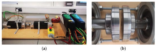
Figure 1.
Experimental test rig (a) motor- and load-side actuation (b) magnetic coupling.
For the driving unit, the motor-side speed and position can be measured, but the load-side speed and position are assumed unavailable for control purposes. This test facility emulates the most common application scenarios for MDTs, where and are ideally not measured. Control effort is electromagnetic torque (), and hence the prime mover is operating in a torque control mode. The driven unit is used to emulate load () variations.
2.2. Dynamic Model
Defining as the torsional torque developed between the two magnetically-coupled shafts, is then given by
where is the relative mechanical displacement angle.
If damping torque is not taken into consideration, MDTs are described by the following set of equations [1].
are considered as state variables, and as inputs, and as the output. Linearizing (2) at an operating point, and letting represent the resulting torsional stiffness , the transfer functions from and to are then, respectively, given by
where .
The anti-resonance frequency () and natural resonance frequency () are then given by
where . Table 1 enumerates and , which ranges from no-load to the 99% of the pull-out torque.

Table 1.
and of the MDT rig subject to various percentages of pull-out torque conditions.
2.3. On-Load Startup and Criteria for MDTs to Maintain Normal Running
On-load startup is the most demanding operating condition that can result in actuation induced pole-slipping, where the relative angle of both shafts is simultaneously developed by the transients of electromagnetic torque demands and load-torque.
If and are considered as step inputs (, and ), then resulting from and can be, respectively, rewritten based on (6) and (7), and are given by
Inverse Laplace transforming of (8) and (9) yields
where . Since is small, . Referring to (10) and (11), the maximum increment of results from when and occur simultaneously and approximates to
It can be seen from (12) that increasing improves the on-load startup capability provided that is fixed (). Moreover, if output exhibits first-order dynamics compared to which is usually assumed to be a step input, would take a much lower value. This also means that low-bandwidth controllers can potentially accommodate a higher on-load startup torque and load-torque disturbances than high-bandwidth designs.
A MDT will enter a pole-slip operating regime if (13) or (14) holds.
where and represent motor- and load-side friction torque. Now, assuming is the relative angle of both shafts while MDTs are running under normal conditions, then a criterion for a MDT to avoid pole-slipping is given by
The experimental study of [6] shows that selecting 75% of the pull-out torque as the operating point can accommodate a wider range of load-torque disturbance. Here, we will show how to use Equations (12), (13), and (15) to estimate the maximum on-load startup torque and the permitted load-torque disturbance that a MDT can accommodate through two example scenarios.
Example 1: supposing the MDT rig is operating at 800 r/min under no-load conditions (), 75% of the pull-out torque is selected as the operating point ( rad/s), and the increment of can immediately follows to find the maximum load-torque disturbance that the MTD rig accommodate without pole-slipping.
Substituting the values of , and into (16) yields . However, due to the delay induced by current/speed control loops, the permitted load-torque disturbance can conceivably be greater than .
Example 2: Assuming 75% of the pull-out torque is selected as the operating point, and is equal to , find the maximum on-load starting torque () that the facility can accommodate without pole-slipping.
3. Controller Design and Pole-Slipping Amelioration
3.1. Virtually Increasing Using Acceleration Feedback
From the analysis above, we know that increasing (effectively decreasing R, see (12)) decreases the possibility of pole-slipping related to on-load startup. Figure 2 shows a model of the MDT with motor-side acceleration feedback ( is the feedback coefficient). Clearly, with acceleration feedback, the equivalent motor-side inertia is given by
Accordingly, the inertia ratio is adjusted to
Letting represent the actual torque developed by the drive, then
Equation (19) indicates the aggressive control effort can be modified by , and this mechanism can be used to prevent exceeding its constraint under on-load startup and inertia mismatch.
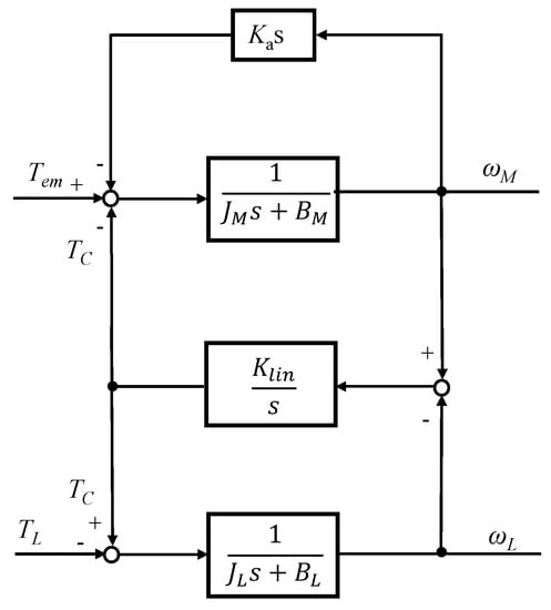
Figure 2.
Block diagram of MDTs with acceleration feedback.
The drive for a practical facility usually integrates period or frequency measurement methods to calculate speed signals with feedback from encoders. However, most drives do not provide acceleration information. Calculating acceleration from speed measurements at a particular sampling frequency will inevitably amplify noise components.
A tracking differentiator (TD) [16] can effectively suppress the amplification of derivative noise while quickly tracking the derivative of input signals without relying on model information. Here, the TD is adopted to obtain an estimation of acceleration.
Supposing tracks the motor-side speed , is the derivative of , then the TD is described by
where r dictates tracking speed, and h is a parameter that determines the filtering effect (, is the sampling period), and is given by
where , and a is given by
with , , .
3.2. Controller Design and Parameter Optimization
The paper now describes the design of a generalized controller (fractional-order controller) represented by
where represent the proportional, integral, and derivative gains and are the order of integrals and derivative items. Of note is that traditional integer PID controllers can be regarded as fractional-order PID controllers (FOPID) with . Hence, the following design process is also applicable for the design of integer-order controllers. Figure 3 shows the principle of optimizing parameters for speed controller using integral of time and absolute error as a performance metric. Specifically, the objective function is considered:
where and is the error of the control loop at time t.
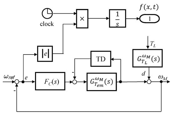
Figure 3.
Block diagram to optimize controller parameters.
The purpose of parameter optimization is to find an x subject to constraints to ensure has a minimum value, described by
where represents general nonlinear inequality constraints; and and are the lower- and upper-boundaries for x, respectively. Normally, can be constructed with a combined specifications of gain crossover frequency, phase margin, gain margin, sensitivity function, and complementary sensitivity function.
From the design perspective of two-mass systems, the gain cross-over frequency () should be set much smaller than to obtain responses similar to that of a low-pass filter, i.e. ideally with no overshoot. It can be seen from Table 1 that rad/s while the MDT rig is running at 90% of the pull-out load-torque. Moreover, the analysis of Section 2.3 shows that a low-bandwidth design can accommodate a wider range of load-torque disturbances. Here, is set to 5 rad/s.
The sensitivity function represents the transfer function from the disturbance (d) to and the speed reference (r) to e, see Figure 3. Equations (10) and (11) show that under excitations takes the form of a step plus a damped oscillation which is regarded as disturbances in this design. To obtain a small control error, is also required to be set small at low frequencies since references usually take the form of relatively low-frequency inputs. Hence, the sensitivity specification for controller design can therefore be given by
Note: here, is assumed to be a value approximately equal to .
The complementary sensitivity function relates speed measurement noise to motor-side speed . Typically, the cut-off frequency of shaft speed filters is usually designed to be 3∼5 ( rad/s while the MDT rig is running at no-load conditions, see Table 1) to meet dynamic processing requirements.The specifications for the complementary sensitivity function are then given by
Previously reported work [17] shows that satisfactory performance can be obtained by setting the gain margin dB and the phase margin . Here, and are chosen to be
The parameters for the TD are and (the sampling frequency for running speed signals is set to 250 Hz). In this case, is set to be (see Figure 2). The optimization is carried out using the open-source software FOMCON [18], and the optimized parameters for the design controller are and . The optimized controller can be further approximated to a classical PI structure as .
3.3. A Criterion for Pole-Slipping Detection
Here, an overload pole-slipping detection methodology is considered. MDTs will enter a pole-slipping regime when the relative mechanical displacement angle between the magnetically-coupled shafts exceeds the designed range. During pole-slipping, will rise for a short period and then return to the reference speed since the speed controller remains in operation. The control effort will therefore converge to be roughly equal to the friction torque in steady state ().
The abrupt change of can be measured by kurtosis, which is a dimensionless indicator widely used for evaluating the characteristics of vibrations. The kurtosis of is derived from [19]
where represents the control effort at time i, and is the mean value of .
A pole-slipping detection criteria can then be described as when
3.4. A Strategy for Pole-Slipping Recovery
It can be seen from the paragraph below Equation (2) that the equivalent torsional stiffness () varies with the displacement angle () between the magnetically-coupled shafts. Once the load-side shaft synchronizes with the motor-side, the displacement angle is constant, resulting in a stable coupling torque (). Hence, the variance of during synchronization is much smaller than the commensurate value when the motor- and load-side speeds are different. The proposed pole-slipping recovery strategy considered here is based on the assumption that can be greater than , and can restore from the state to . The proposed recovery strategy is summarised as follows:
- At the onset of pole-slipping, reverse the running direction of the motor-side shaft and control the speed of it up to the maximum specification speed, then;
- Control the electromagnetic torque to be zero (); will consequently then decrease;
- As decreases, the motor-side shaft will re-synchronize with the load-side shaft (the variance of is now used as a synchronization detection indicator). The PI plus TD configuration can then be reconfigured to control the MDT to the reference speed.
4. Simulation and Experimental Results
To verify the theoretical analysis in Section 2.3, this Section will initially consider three cases of on-load startup (first case: , second case: , third case: ) through simulation. For the discussed cases, the electromagnetic torque is assumed to be saturated immediately (). Note that in this paper, and are normalized at for both simulation and experimental trials.
Figure 4a shows the simulation results for . It can be seen that slip between two shafts of the MDT occurs while is or above. Although increasing results in a slower transient response, Figure 4b shows that the on-load starting torque can be up to by modifying to 2. However, as shown in Figure 4c, by setting to 0.5, the two sides of the MDT are out of synchronization in all studied cases. It is clear that decreasing the inertia ratio through increasing improves on-load startup capability. In practice, low-cost drives often cannot provide sufficient bandwidth for their current control loops. Hence, the output electromagnetic torque and load-toque are assumed to exhibit first-order dynamics. Under these circumstances, from Equation (12) and subsequent discussion, the permitted on-load startup torque can be a higher value compared with the simulation studies.
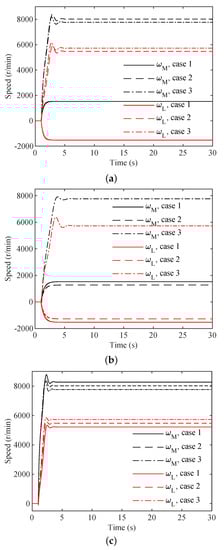
Figure 4.
Simulation results of on-load startup: (a) R = 1 ( = 0.001 kg·m); (b) R = 0.5 ( = 0.002 kg·m); (c) R = 2 ( = 0.0005 kg·m).
Figure 5 shows tshows the measured load rejection dynamics for the optimized controller. As shown in Figure 5a, the speed of load-side coupling follows the motor-side without speed oscillations even when the MDT rig is subject to 2 significant load disturbances. Figure 5b shows that by adjusting the inertia ratio with offers first-order filter dynamics for the reactive control effort compared to the step load-torque disturbance occurring at 13 s. This characteristic greatly improves the range of load-torque disturbance and on-load startup torque that the MDT rig can accommodate while referring to (10), (11), and (12). It can also be seen from Figure 5b that the peak control effort resulting from the speed reference is about 0.7. Assuming (remove the acceleration feedback) and can immediately follow without overshoot, the maximum on-load startup torque would be around 0.48 if friction torque is included (as shown in Figure 5b, at around 800 r/min).
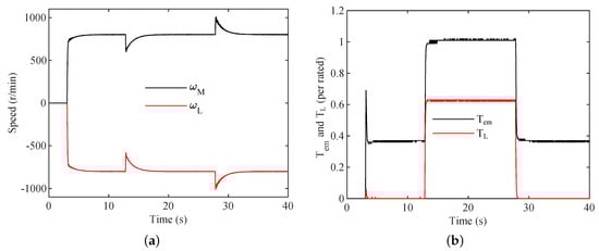
Figure 5.
Experimental responses using the optimized controller with (speed reference is imposed at 1 s; is set to 0%, 63%, and 0% of the pull-out torque at 1–13 s, 13–28 s, and 28–40 s, respectively): (a) shaft speed of on both sides of the magnetic coupling; (b) and .
The on-load startup torque is now set to 0.63. Figure 6 shows that virtually increasing through acceleration feedback overcomes the pole-slipping problem associated with on-load startup and that a starting load-torque that is greater than 0.63 can lead the MDT to pole-slipping ( slightly exceeds at around 1.8 s; however, the effective coupling torque is still a slightly lower than due to the existence of motor-side friction). Of note is that if load-side friction torque () is considered, the maximum on-load starting torque is 0.81 in this case.
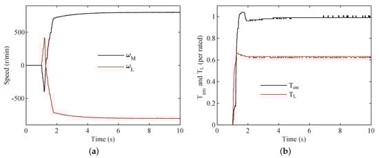
Figure 6.
Experimental measurement while starting with 63% of the pull-out torque ( and are imposed at 1 s, simultaneously): (a) speed of both side shafts; (b) and .
It can also be seen from the experimental trials that the inertia ratio is set to 0.09 () to prevent pole-slipping resulting from on-load startup and inertia mismatch. By contrast, previously reported work [12,13,20] shows that effective oscillation suppression is achieved by setting the resonance ratio () of two-mass systems to be ; thus, R ranges between 1 and 4 (see (5)). Although MDTsare traditionally regarded as two-mass systems, it can be seen from the simulations and experimental trials that the recommended inertia ratio for MDTs should generally be set much lower than that of classical two-inertia systems to prevent MDTs from entering pole-slipping initiated by the combined effects of and .
The efficacy of pole-slipping detection and recovery strategies are now investigated. Figure 7b shows that the kurtosis of is lower than three, when the MDT is operating in normal conditions. However, the kurtosis rises dramatically to 8.71 during the period of 10.42 s to 12.64 s (pole-slipping occurs at 12.1 s). It can also be seen from Figure 7a that at around 12.5 s. Hence, the proposed method can effectively detect the transition to pole-slipping.
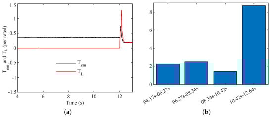
Figure 7.
Pole-slipping detection using kurtosis: (a) the output of with respect to ; (b) kurtosis of (pole-slipping occurs at 12.1 s, and kurtosis is calculated individually with 200 samples of output).
The experimental results shown in Figure 8 provide an example of the recovery strategy. As shown in the figure, pole-slipping is induced at 12 s. At the beginning of pole-slipping, the load-side shaft reverses its direction due to being temporarily higher than the maximum coupling torque and . Following that, the load-side shaft loses synchronization with the primary-side, running at around 1600 r/min during pole-slipping. After detecting pole-slipping with the kurtosis methodology discussed above, the motor-side drive reverses its running direction from 14 s and controls to 2000 r/min, a setting higher than . It can be seen from Figure 8 that the motor-side speed varies around 2000 r/min from at 16 s and that the variance of increases considerably when both side speeds are different. From 25 s to 30 s, is set to 0, then decreases. Following that, the motor-side shaft synchronizes with the load-side shaft from roughly 27 s. Now, the coupling torque is relative constant; therefore, speed oscillations are reduced. This is a situation that can be regarded as on-load startup. The reconfigured scheme can then be used to recover the MDT rig from pole-slipping. It can be seen from the figure that the MDT recovers after 30 s. According to Table 2, the variance of during the period of 19–21 s ( r/min, r/min) is far higher than the variance calculated from 9 s–11 s or 27 s–29 s (). Hence, the variance of is a suitable indicator for synchronisation.
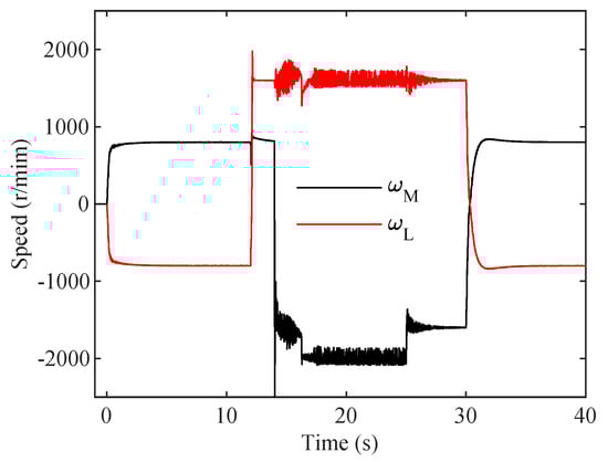
Figure 8.
Experimentally measured speed of both coupled shafts components before, during, and after the overload condition.
Table 2.
Variance of .
5. Conclusions
In this paper, pole-slipping anomalies induced by electromagnetic inputs and load-torque disturbances are investigated. Experimental trials have been used to verify that a low-bandwidth controller design incorporating a tracking differentiator to virtually increase motor-side inertia significantly improves the on-load startup performance and load-torque disturbance handling range for the MDT where acceleration feedback is unavailable. MDTs are traditionally classified as two-inertia systems; however, the experimental trials show that an appropriate inertia ratio for MDTs to maintain normal operation is much lower than that of traditional dual-inertia control systems. Experimental measurements have confirmed that the proposed amelioration methods can effectively detect pole-slipping without using load-side position/speed measurements and can overcome the requirement for including additional mechanic devices to facilitate recovery.
Author Contributions
Conceptualization, X.L., C.B. and T.S.; formal analysis, X.L.; project administration, C.B.; software, X.L.; supervision, C.B.; experiment investigation, X.L., C.B. and T.S.; writing—original draft, X.L.; writing—review and editing, C.B.. All authors have read and agreed to the published version of the manuscript.
Funding
This research received no external funding.
Institutional Review Board Statement
Not applicable.
Data Availability Statement
Not applicable.
Acknowledgments
The authors would like to thank Argyrios Zolotas for inspiring to employ fractional-order control as the control scheme.
Conflicts of Interest
The authors declare no conflict of interest.
Abbreviations
| Anti-resonance frequency (rad/s) | |
| The frequency of damped sine signal (rad/s) | |
| Load-side angular velocity (rad/s) | |
| Motor-side angular velocity (rad/s) | |
| Natural resonance frequency (rad/s) | |
| Load-side angle (rad) | |
| Motor-side angle (rad) | |
| (rad) | |
| Damping coefficient (kg/s), and | |
| Integer order | |
| Derivative order | |
| Load-side friction coefficient N·m/(rad/s) | |
| Motor-side friction coefficient N·m/(rad/s) | |
| Load-side inertia (·) | |
| Motor-side inertia (·) | |
| The equivalent value of motor-side inertia (·) | |
| Feedback coefficient | |
| Derivative gain | |
| Integral gain | |
| Proportional gain | |
| Linearized torsional stiffness (m/rad) | |
| p | Pole-pairs |
| R | Inertia ratio () |
| Coupling torque (m) | |
| Electromagnetic torque (m) | |
| Load-side friction torque (m) | |
| Motor-side friction torque (m) | |
| Load torque (m) | |
| The maximum coupling torque (m) |
References
- Montague, R.; Bingham, C.; Atallah, K. Servo control of magnetic gears. IEEE/Asme Trans. Mechatron. 2011, 17, 269–278. [Google Scholar] [CrossRef]
- Atallah, K.; Howe, D. A novel high-performance magnetic gear. IEEE Trans. Magn. 2001, 37, 2844–2846. [Google Scholar] [CrossRef]
- Wang, Y.; Filippini, M.; Bianchi, N.; Alotto, P. A Review on Magnetic Gears: Topologies, Computational Models and Design Aspects. IEEE Trans. Ind. Appl. 2019, 55, 4557–4566. [Google Scholar] [CrossRef]
- Rasmussen, P.O.; Andersen, T.O.; Jorgensen, F.T.; Nielsen, O. Development of a high-performance magnetic gear. IEEE Trans. Ind. Appl. 2005, 41, 764–770. [Google Scholar] [CrossRef]
- Jorgensen, F.T.; Andersen, T.O.; Rasmussen, P.O. The Cycloid Permanent Magnetic Gear. IEEE Trans. Ind. Appl. 2008, 44, 1659–1665. [Google Scholar] [CrossRef]
- Liao, X.; Bingham, C.; Zolotas, A.; Zhang, Q.; Smith, T. Servo Control of Drive-Trains Incorporating Magnetic Couplings. IEEE Trans. Ind. Appl. 2022, 58, 3674–3684. [Google Scholar] [CrossRef]
- Montague, R.; Bingham, C.; Atallah, K. Dual-observer-based position-servo control of a magnetic gear. IET Electr. Power Appl. 2011, 5, 708–714. [Google Scholar] [CrossRef]
- Bouheraoua, M.; Wang, J.; Atallah, K. Rotor position estimation of a pseudo direct-drive pm machine using extended kalman filter. IEEE Trans. Ind. Appl. 2016, 53, 1088–1095. [Google Scholar] [CrossRef]
- Bouheraoua, M.; Wang, J.; Atallah, K. Design and implementation of an observer-based state feedback controller for a pseudo direct drive. IET Electr. Power Appl. 2013, 7, 643–653. [Google Scholar] [CrossRef]
- Montague, R.; Bingham, C.; Atallah, K. Magnetic gear dynamics for servo control. In Proceedings of the MELECON 2010–2010 15th IEEE Mediterranean Electrotechnical Conference, Valletta, Malta, 26–28 April 2010; pp. 1192–1197. [Google Scholar]
- Bouheraoua, M.; Wang, J.; Atallah, K. Slip recovery and prevention in pseudo direct drive permanent-magnet machines. IEEE Trans. Ind. Appl. 2014, 51, 2291–2299. [Google Scholar] [CrossRef]
- O’Sullivan, T.M.; Bingham, C.M.; Schofield, N. High-performance control of dual-inertia servo-drive systems using low-cost integrated SAW torque transducers. IEEE Trans. Ind. Electron. 2006, 53, 1226–1237. [Google Scholar] [CrossRef]
- Saarakkala, S.E.; Hinkkanen, M. State-space speed control of two-mass mechanical systems: Analytical tuning and experimental evaluation. IEEE Trans. Ind. Appl. 2014, 50, 3428–3437. [Google Scholar] [CrossRef]
- Szabat, K.; Orlowska-Kowalska, T. Vibration Suppression in a Two-Mass Drive System Using PI Speed Controller and Additional Feedbacks—Comparative Study. IEEE Trans. Ind. Electron. 2007, 54, 1193–1206. [Google Scholar] [CrossRef]
- Montague, R.G.; Bingham, C.; Atallah, K. Magnetic gear pole-slip prevention using explicit model predictive control. IEEE/ASME Trans. Mechatronics 2012, 18, 1535–1543. [Google Scholar] [CrossRef]
- Han, J. From PID to active disturbance rejection control. IEEE Trans. Ind. Electron. 2009, 56, 900–906. [Google Scholar] [CrossRef]
- Ogata, K. Modern Control Engineering; Prentice Hall: Upper Saddle River, NJ, USA, 2010; Volume 5. [Google Scholar]
- Tepljakov, A. FOMCON: Fractional-order modeling and control toolbox. In Fractional-Order Modeling and Control of Dynamic Systems; Springer: Berlin/Heidelberg, Germany, 2017; pp. 107–129. [Google Scholar]
- Immovilli, F.; Cocconcelli, M.; Bellini, A.; Rubini, R. Detection of generalized-roughness bearing fault by spectral-kurtosis energy of vibration or current signals. IEEE Trans. Ind. Electron. 2009, 56, 4710–4717. [Google Scholar] [CrossRef]
- Hori, Y.; Sawada, H.; Chun, Y. Slow resonance ratio control for vibration suppression and disturbance rejection in torsional system. IEEE Trans. Ind. Electron. 1999, 46, 162–168. [Google Scholar] [CrossRef]


Publisher’s Note: MDPI stays neutral with regard to jurisdictional claims in published maps and institutional affiliations. |
© 2022 by the authors. Licensee MDPI, Basel, Switzerland. This article is an open access article distributed under the terms and conditions of the Creative Commons Attribution (CC BY) license (https://creativecommons.org/licenses/by/4.0/).