Abstract
The large-scale numerical simulation of complex flows has been an important research area in scientific and engineering computing. The lattice Boltzmann method (LBM) as a mesoscopic method for solving flow field problems has become a relatively new research direction in computational fluid dynamics. The multi-layer grid-refinement strategy deals with different-level of computing complexity through multi-scale grids, which can be used to solve the complex flow field of the non-uniform grid LBM without destroying the parallelism of the standard LBM. It also avoids the inefficiencies and waste of computational resources associated with standard LBMs using uniform and homogeneous Cartesian grids. This paper proposed a multi-layer grid-refinement strategy for LBM and implemented the corresponding parallel algorithm with load balancing. Taking a parallel scheme for two-dimensional non-uniform meshes as an example, this method presented the implementation details of the proposed parallel algorithm, including a partitioning scheme for evaluating the load in a one-dimensional direction and an interpolation scheme based on buffer optimization. Simply by expanding the necessary data transfer of distribution functions and macroscopic quantities for non-uniform grids in different parallel domains, our method could be used to conduct numerical simulations of the flow field problems with complex geometry and achieved good load-balancing results. Among them, the weak scalability performance could be as high as 88.90% in a 16-threaded environment, while the numerical simulation with a specific grid structure still had a parallel efficiency of 77.4% when the parallel domain was expanded to 16 threads.
1. Introduction
The numerical simulation of complex flow field problems has been one of the most significant and challenging research areas in large-scale scientific and engineering computation. The lattice Boltzmann method (LBM), which starts from the Boltzmann equation, describes fluid systems and thermodynamic phenomena in physical scenarios from the mesoscopic scale. The use of simple microscopic models to simulate the macroscopic behavior of transport phenomena is also a well-established solution in computational fluid dynamics (CFD) [1,2]. With the mesoscopic description of thermal effects being added under the LBM model, LBM has gradually become an important and successful numerical tool for solving various fluid flow and heat transfer systems in recent decades. Related research is of great importance in the fields of energy engineering and chemical engineering. Chen and Qian et al. independently proposed the Single Relaxation Time (SRT) or BGK (Bhatnagar–Gross–Krook) model, respectively [3,4]. This model uses a single relaxation coefficient instead of a matrix pattern of collision terms. It is used to control the velocity of particles in different directions approaching their respective equilibrium states. Because of its simplicity and validity, the single relaxation lattice Boltzmann model is one of the most widely accepted lattice Boltzmann models. The French scholar d’Humières presented the generalized lattice Boltzmann model (GLBM) at a conference in 1992 [5] after the SRT model was proposed. A careful theoretical analysis of the model was conducted by Lallemand and Luo in 2000. The results showed that the GLBM has great advantages in terms of physical principles and numerical stability [6]. The main difference between the GLBM and the SRT model is the multiple relaxation time for the collision process. Therefore, it is also called the Multiple Relaxation Time (MRT) model. The LBM has several unique advantages. The first is the simplicity of the Cartesian grid structure and the simplicity of performing operations such as collision, streaming and boundary updating. Secondly, it can be scaled in ease to simulate a large variety of flow scenarios. Finally, it allows the flexible manipulation of complex boundary conditions [7,8,9]. These properties allow the LBM to be considered as an effective method for simulating complex fluid systems.
For the standard LBM, the numerical simulation is usually adopted with a uniform and homogeneous Cartesian grid. For numerical simulations of complex flows, especially in three dimensions, the uniform Cartesian mesh used for the simulation needs to be as refined as possible in order to achieve better accuracy, and the mesh volume will increase exponentially. This will lead to a rapid increase in computational cost. High-performance computing technology and parallel environments provide efficient, promising and reliable solvers to handle the large-scale computational problems of the LBM. Therefore, it is evident that high-performance computing is the best option for fulfilling the numerous computational demands for the simulation of complex flows [10,11]. Williams et al. investigated how to achieve better performance from the LBM on a multicore platform [12]. Lacoursière et al. presented a hybrid block-parallel method for solving complementary problems in approximate real-time on multi-core CPUs [13]. Donath et al. analyzed varying lattice Boltzmann parallel computational implementations on a multi-core, multi-socket system [14]. In addition, many of the existing frameworks for the LBM [15,16,17] are designed for parallel computing, and many of them exhibit excellent scalability, i.e., their performance grows linearly with the number of processors employed.
The inherent advantage of the LBM is related to the use of regular meshes with uniform grid spacing. Obviously, this regularity limits the application domain of the LBM from an efficiency aspect, since uniform meshes are less suitable for simulating flows with strong local gradients. From the point of view of physical phenomena and simulation scenarios, only a small part of the entire flow field area must be high-resolution in a complex flow simulation. It is not necessary to refine all flow field areas. In order to focus computational resources on the regions where high accuracy is required, many advanced methods in computational fluid dynamics rely on grid refinement. Initially, the LBM is a finite difference scheme. This means that interpolation of the particle distribution is necessary for cases where exact boundary conditions or local mesh refinement techniques are applied and mass conservation conditions cannot be easily imposed. When considering locally embedded meshes, the LBM uses the same treatment scheme. Filippova and Hänel firstly introduced the local grid-refinement treatment to the LBM [18]. The main advantages of the local grid-refinement processing method are as follows. On the one hand, the evolution time step on the coarse grid is larger and less computationally demanding, so that the boundary information can be propagated faster over the entire flow field region to obtain the general structure of the flow. On the other hand, a fine grid can capture the flow information in the region of drastic changes [19]. It can balance computational efficiency and accuracy because the evolution of this method on coarse and fine grids is coupled in both directions. Lin and Lai developed a unidirectional coupling method based on the exchangeability of distribution functions on different grids based on this method [20]. The method from Filippova and Hänel is unstable in some cases. In addition, the distribution functions can be exchanged on different resolution grids in the method from Lin and Lai, which can lead to certain errors. To solve the problem, Dupuis and Chopard constructed a local grid-refinement method that considers the distribution function and bidirectional coupling. An acceleration method was proposed that can significantly improve the computational efficiency [21]. Node-based [22,23,24] and volume-based [25,26,27] approaches have been proposed to incorporate grid refinement into the LBM [28].
The distribution functions of the LBM are located at the centers of the lattice cells in the volume-based methods. During the refinement process, the coarse grid cells are uniformly subdivided into numerous finer grid cells. The volume-based methods prevent the centers of coarse and fine grid cells from overlapping. The volume-based mesh refinement method of the LBM already guarantees mass and momentum conservation, so rescaling the nonequilibrium part of the distribution function is not necessary. For volume-based grid refinement, P. Neumann et al. [27] and M. Hasert et al. [26] proposed parallelization methods suitable for large-scale cluster systems. Both grid-refinement schemes require a tree partition based on the simulation area, such that the grid structure is tightly linked to the communication between partitions. So, both authors used a partitioning scheme of space-filling curves applied to a parallel framework, which allows good scalability and limited high performance of these parallel systems. In contrast, Schornbaum et al. in their research work required that the grid cells at all levels be distributed to all provided parallel domains to achieve task load balancing [28]. The grid domains with different resolutions are partitioned into parallel tasks using the graph partitioning library Metis METIS, thus significantly reducing the communication consumption. The approach of this paper retained Schornbaum’s idea of separate grid partitioning for different levels and designed a new partitioning strategy instead of the graph partitioning library Metis METIS in order to further achieve load balancing. Other well-known LBM-based simulation codes, such as Palabos [29], OpenLB [30], LB3D [31], HemeLB [32], HARVEY [33] and LUDWIG [34], either do not enable mesh refinement or only do so for 2D issues or have not yet demonstrated large-scale numerical simulations on non-uniform meshes.
The paper explored a parallel algorithm for the LBM with hierarchically refined meshes. In the latter part of this article, the LBM with hierarchically refined meshes are referred to as a multi-layer grid LBM. On such a grid structure, this paper explored a load-balancing-based parallel algorithm to solve the computational efficiency problem of the multi-layer grid LBM. The mentioned load in this paper mainly considered the computational load and memory consumption. A series of numerical simulation experiments were conducted. The accuracy and stability of the multilayer mesh LBM and its parallel scheme in this paper were finally verified. The parallel effect of the parallel algorithm based on the load-balanced mesh partitioning strategy proposed in this paper was also analyzed. In addition, the results affirmed the feasibility of the method in this paper. This involved further exploration of the complex multi-layer grid-refinement strategy and the load-balancing techniques associated with it. In addition, new forms of the LBM such as the Multi-speed (M-S) model and Multi-Distribution Function (MDF) model were mostly used to analyze fluid flow and heat transfer, which led to more significant developments in the numerical simulation of the LBM in the energy field dealing with systems with heat transfer [35]. With a diverse range of solutions and a proven code framework, the high-performance LBM can provide efficient solutions to the latest application simulation scenarios for energy problems, including nanofluids, energy storage devices, as well as systems with electro-thermo convection [36,37,38].
2. Multilayer Grid Lattice Boltzmann Method
2.1. LBM
2.1.1. Governing Equation
The microscopic motions of molecules in any macroscopic system obey the laws of mechanics. By calculating the individual motions of a large number of particles in a simulated space, most macroscopic parameters of a physical system can be determined. Based on this starting point, molecular dynamics simulations were developed. Understood differently, the basic idea of Boltzmann’s equation is not to determine the motion state of an individual molecule, but to find the probability that each molecule is in a certain status and to derive the macroscopic parameters of the system by statistical methods [39].
An explicit finite difference method is used in the LBM. In each time step, information is only exchanged between adjacent grid cells. Due to its data locality, it is very suitable for parallelization. The corresponding particle distribution function is stored in each grid cell. In order to numerically solve the particle distribution function under conservation law conditions, the method must first use a finite set of velocities in velocity space. From it, the velocity discretization of the lattice Boltzmann equation (LBE) is implemented. The following equation gives the LBM for a single relaxation time (SRT) model with a finite set of velocity vectors [40].
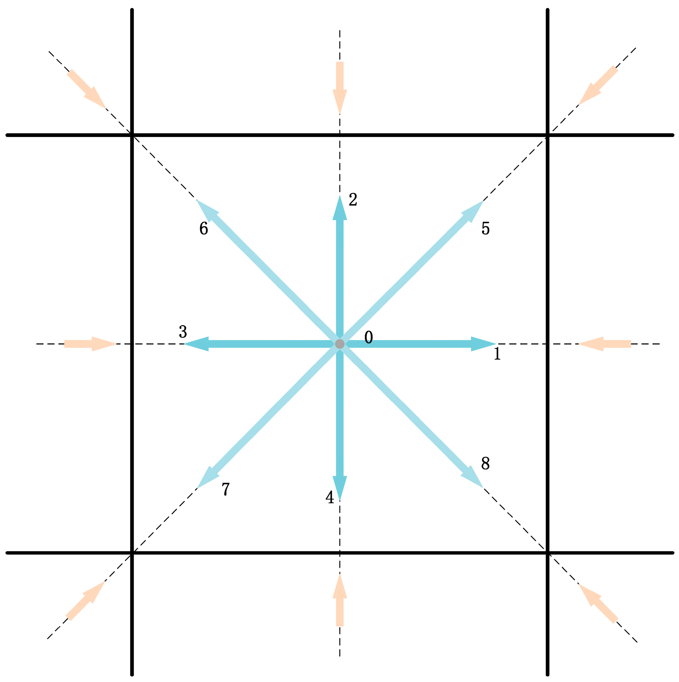
where and are the particle distribution function and equilibrium distribution function related to the discrete velocity at respectively. is the relaxation time. is the viscosity. It is derived from the equation , where is the gas constant and is the gas temperature. In the development of LBM, the two-dimensional nine-velocity (D2Q9) lattice model has been widely and effectively applied in simulation experiments of two-dimensional flow. The velocity discretization of the D2Q9 lattice model at one lattice center is shown in Figure 1. For the D2Q9 model [41], the discrete velocity set is written as [42]:
where , and are the lattice constant and time step size, respectively, and the equilibrium distribution of the D2Q9 lattice model is [43]
where is the weighting factor given by the following formula [40]:
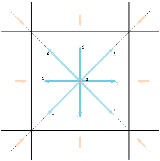
Figure 1.
D2Q9 lattice model.
Equation (1) is called the Discrete Velocity Model (DVM). It can be solved numerically by any standard and practical method. In the LBE method, Equation (1) can be completely discretized in space and time with time step and space step . The further discrete form of the governing equation can be written as:
where is the discrete velocity set and the relaxation time is . Equation (3) is called the LBE with BGK approximation or the LBGK model [44]. It is usually solved in the following two steps:
From the above collision and streaming steps, it can be seen that the collision step is only carried out on its own grid cell and does not involve information from other grid cells. The streaming step involves changes in time and space positions. When calculating the streaming step, the grid calculation requires the use of information from neighboring grid cells along the velocity direction on the grid cell. Whether the model is a complex discrete velocity model or has a large number of discrete velocity directions, the information exchange during migration is only local and does not involve global information. In the discretized velocity space, the density and momentum fluxes can be calculated using the following formulas:
It can be seen from the above formula that the update calculation of the macroscopic quantity can only be performed on its own grid cells, so the LBM has great parallelism.
2.1.2. Boundary Conditions
The dynamic characteristics of fluid flow have a great relationship with its surrounding environment. Mathematically, the effect of the surrounding environment on the fluid is expressed by boundary conditions. After each time step, the distribution functions on the flow field grid cells are obtained for the computational domain. However, some of the distribution functions on the boundary grid cells are unknown. The corresponding distribution function values on the boundary nodes need to be determined based on the known macroscopic boundary conditions. This requires a different boundary treatment in the post-collision/pre-flow step. Parallel boundary processing will have a great impact on the accuracy, stability and efficiency of numerical calculations. According to the type of boundary conditions to deal with the practical problem, the boundary-processing method can be divided into two cases: the straight boundary and the curved boundary. The following describes the LBM boundary-treatment method based on the D2Q9 model to simulate free flow on solids.
- (a)
- Straight boundary.
Generally speaking, the boundary conditions of the solid wall velocity can only be approximately satisfied by solving . The rebound format is a commonly used boundary processing format for dealing with non-slip walls. In this solution, the particles are assumed to collide with the wall. Then, the particles on the boundary are bounced and reversed in the direction opposite to the original direction of the particles. It is equivalent to setting . This scheme is suitable for the horizontal wall used in the simulation experiment.
When the inlet velocity is given, the rebound scheme of the solid wall is directly extended to deal with the inlet boundary. The bounce-back boundary condition requires a certain amount of momentum to be applied to the particles being rebounded, and the distribution function change is of the following form:
where , is the grid cell position on a particular wall, is the weight, and is the given velocity on the wall. The boundary condition uses the second-order exact extrapolation boundary condition at the outlet boundary with the following equation [45]:
- (b)
- Curved boundary.
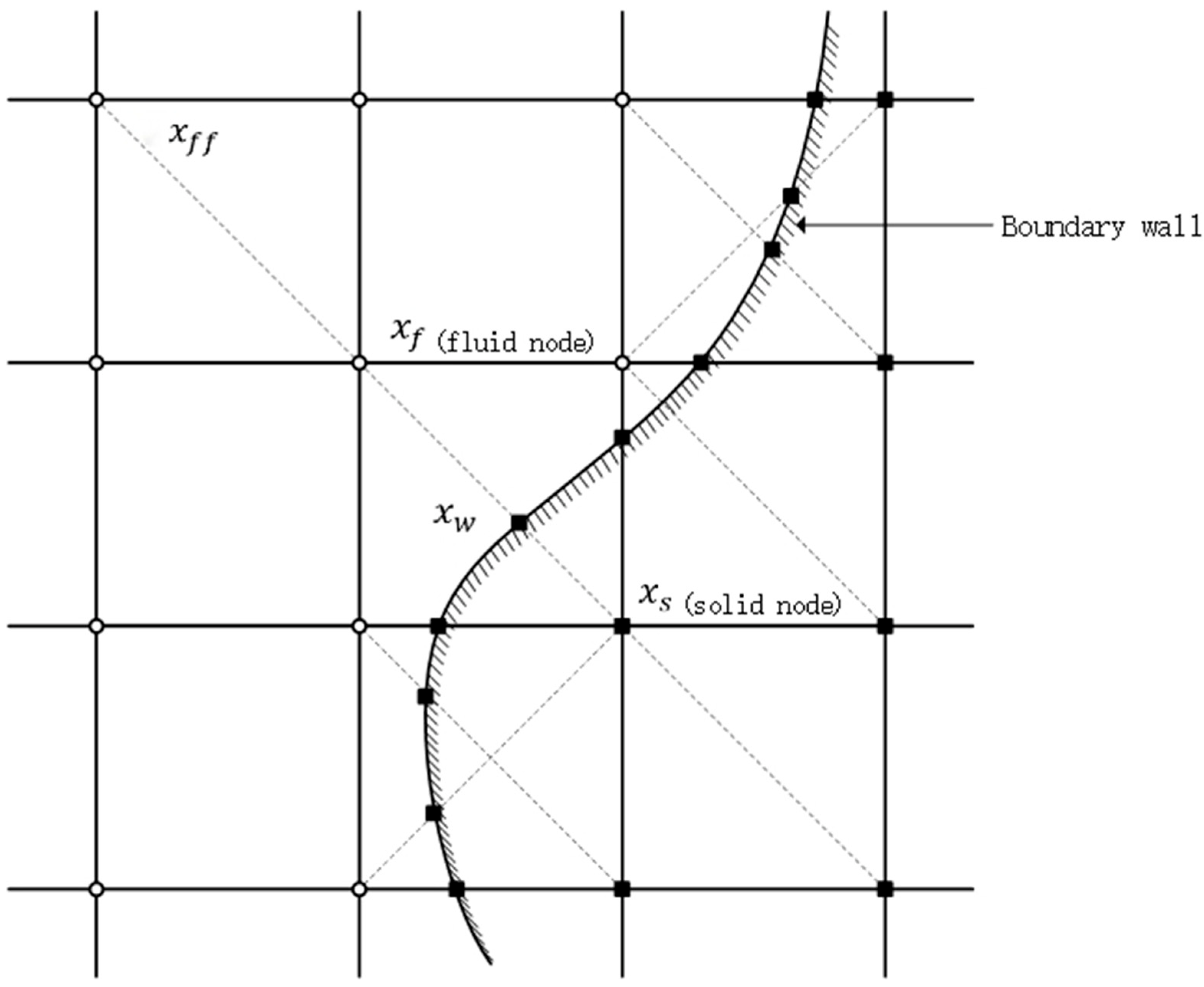
The physical region that needs to be handled frequently has complex geometric shapes in the numerical simulation of genuine problems (see Figure 2). If the bounce-back boundary condition in the straight boundary is directly used to calculate this kind of flow field with complex boundaries, the accuracy of the numerical calculation results will be lower. Therefore, many scholars have studied the complex boundary-processing format of LBM. Gradient approximation or interpolation processing is used at appropriate locations to ensure that the conditions on the physical boundary are satisfied.
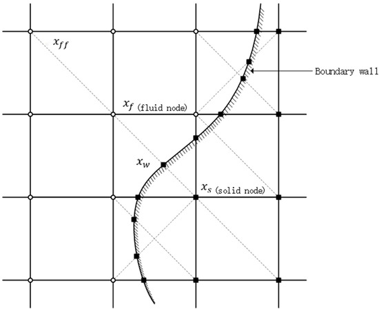
Figure 2.
Schematic diagram of node types on complex boundaries. There is a migration process between and point in the figure. The calculation requires knowing the location distribution function from the boundary point into the fluid node .
In the collision process, fluid particles located on the same grid point collide with each other to determine the distribution function after the collision. In the streaming process, fluid particles in different directions move along the grid lines and migrate to adjacent grid points. It can be seen that the collision process only occurs at the location of the node itself. The streaming process needs to transfer the corresponding distribution function to the adjacent grid node along the grid velocity direction. In order to facilitate the description, it is necessary to distinguish the types of grid points. Assume that is the grid velocity of the fluid to the boundary grid cell. is the grid velocity in the opposite direction. Then, the expression of the unknown distribution function on the boundary grid point during migration moving into the fluid node along the direction is:
is not determined during the collision process, so it must be calculated after the collision process and before the migration process. The difference between various complex boundary processing formats is how to calculate or .
At present, there are many curved boundary conditions in the literature, including the Filippova and Hänel formats [18] and their improved forms, the Bouzidi format [46], the Lallemand and Luo format [47], etc. Here, we give the YMS format proposed by Yu based on linear interpolation and rebound treatment (YMS is the initials of Yu, Mei and Shyy, respectively) [48]. This format is suitable for straight-line fixed walls and curved fixed-wall boundaries at any position, and it can also guarantee second-order accuracy.
Suppose the direction from the grid point to the boundary grid point in the basin is , and the reverse is . The processing of the YMS curve boundary format is to determine the distribution function that streams from the solid grid point to the fluid grid point, and let us introduce a reference quantity that describes the specific position of the actual physical boundary between the grids.
Obtained by linear interpolation:
where represents the distribution function after the collision, and the last term in the formula represents the motion speed of the curve boundary.
2.2. Local Grid-Refinement Method
The most appropriate computation grid for the lattice Boltzmann technique is a Cartesian grid since the LBM is based on a symmetrical discrete velocity model. The calculation process of this method includes collision and streaming. Streaming steps occur only in the direction of the discrete velocity. There are frequently regions in the flow field where the physical quantity drastically changes, with significant spatial and temporal gradients. To resolve this concern, local fine grids are frequently utilized in computational fluid dynamics. The advantage of the local grid-refinement method is that the evolution time step on the coarse grid is relatively large. The computational effort is also smaller. So, the boundary information can be quickly propagated to the whole flow field to achieve the general flow structure. The finer grid can capture the flow information in the drastically changing area. As a result, it can take into account the calculation efficiency and accuracy.
In the locally refined grid used in this work, the size of the grid cell, i.e., its width, is derived from its refinement level . The deduced formula is , where is the computational domain length of the outermost coarse grid cells. On a non-uniform grid with multi-layer refinement, the refinement ratio of adjacent grid cells is traditionally set to , where refers to the coarse grid, and refers to the fine grid. Therefore, grid cells at the refinement level can be subdivided isotropically into 4 sub-grid units to become the refinement level . Since the evolution equation of a multilayer Cartesian grid is essentially a superposition of multiple two-layer grid evolution methods, this section uses a two-layer grid to describe it. Further, assume that the coarse grid step size is times the fine grid step size . In order to ensure the consistency of fluid viscosity and the Reynolds number in the entire flow field, the relaxation time in the coarse grid and the relaxation time in the fine grid need to satisfy the following relationship:
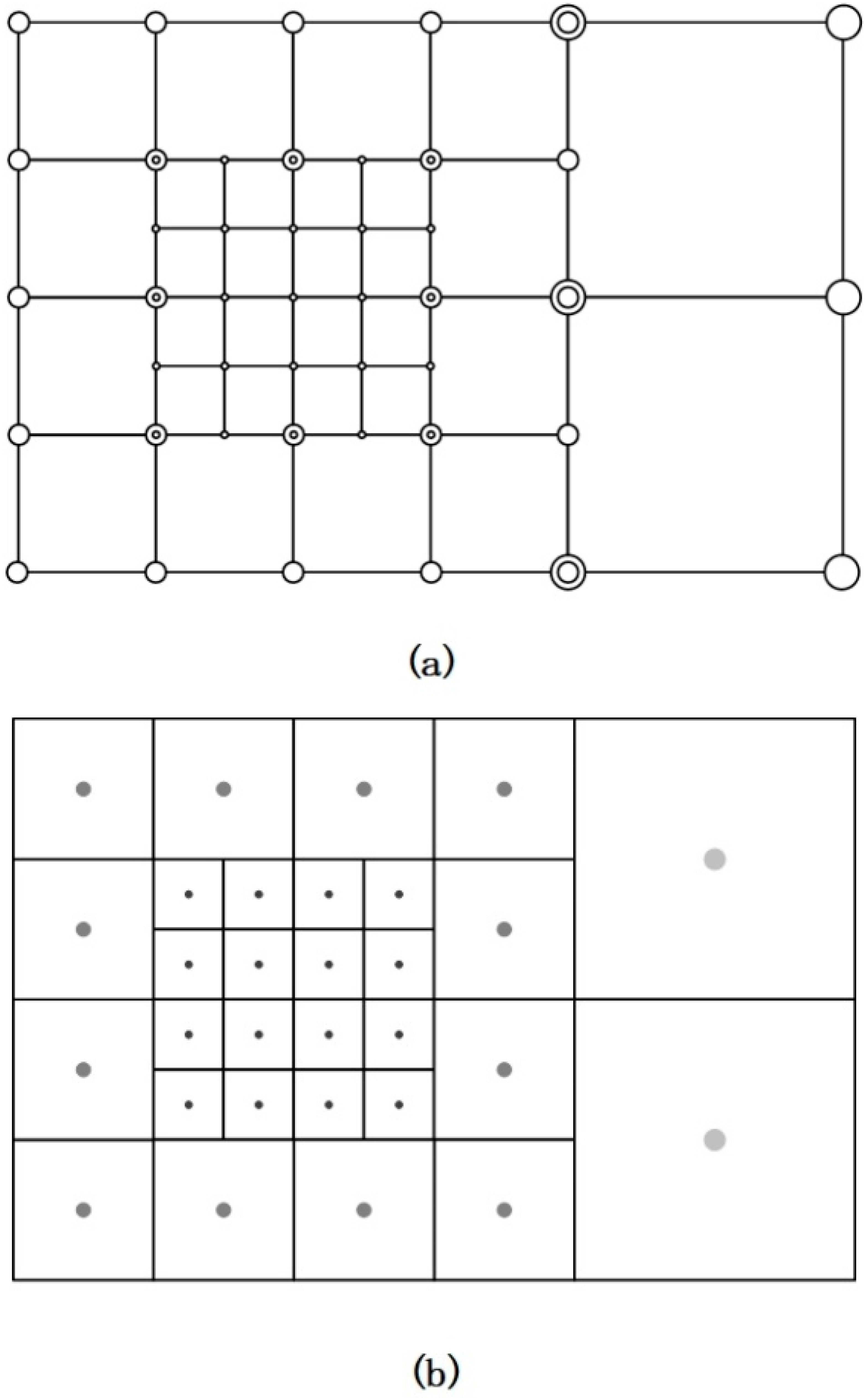
The storage structure of multi-layer grid usually has two structures: node-based approaches (see Figure 3a) and volume-based approaches (see Figure 3b).
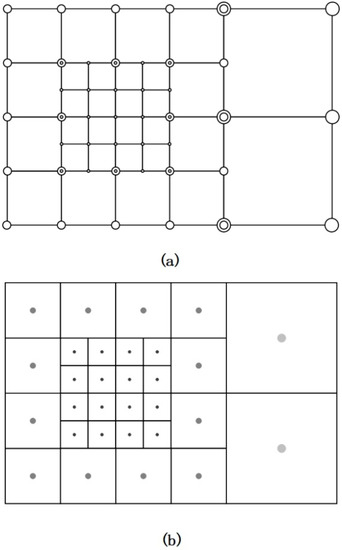
Figure 3.
Two grid arrangements at the refinement interface. The circles indicate the grid points where the grid information is recorded, where large circles indicate coarse grid cells and small circles indicate fine grid cells. In the node-based approaches (a), the coarse and fine grid cells are overlapped in the intersection part of the grid with different layers. In the volume-based approaches (b), all the grid information is recorded by the grid center point.
In this study, the pre-collision distribution function was reconstructed, and the cell-centered lattice structure shown in Figure 3b was selected. Since the center points of the grid are recorded, the positions of these center points will not be repeated. When the grid computing domain is divided into multiple parts for parallel computing, evaluating the distribution function at the center of the grid cell is a reliable solution because the control volume of the grid cell can be allocated to a single parallel computing domain. At the same time, the process of grid point refinement is actually to divide a grid into multiple grids. If the center point of the grid is used to represent a grid, the result of this kind of storage is similar to the fork-tree structure. The increase in the number of grid levels only needs to increase the depth of the fork tree, which is convenient for programming operations. Based on the above analysis, here the paper uses the volume-based approaches to store the multi-layer grid.
On the interface between the computational domains of different resolutions, there are adjacent grid cells with different refinement levels, because the direct propagation of the distribution function is not desirable. Communication between adjacent blocks must be achieved by a specific refinement scheme that maintains the conservation of mass and momentum. Dupuis and Chopard developed a local mesh-refinement method (DC method) based on the distribution function and bidirectional coupling. According to the fact that density and velocity are independent of the mesh, the relationship between the coarse and fine mesh distribution functions is established:
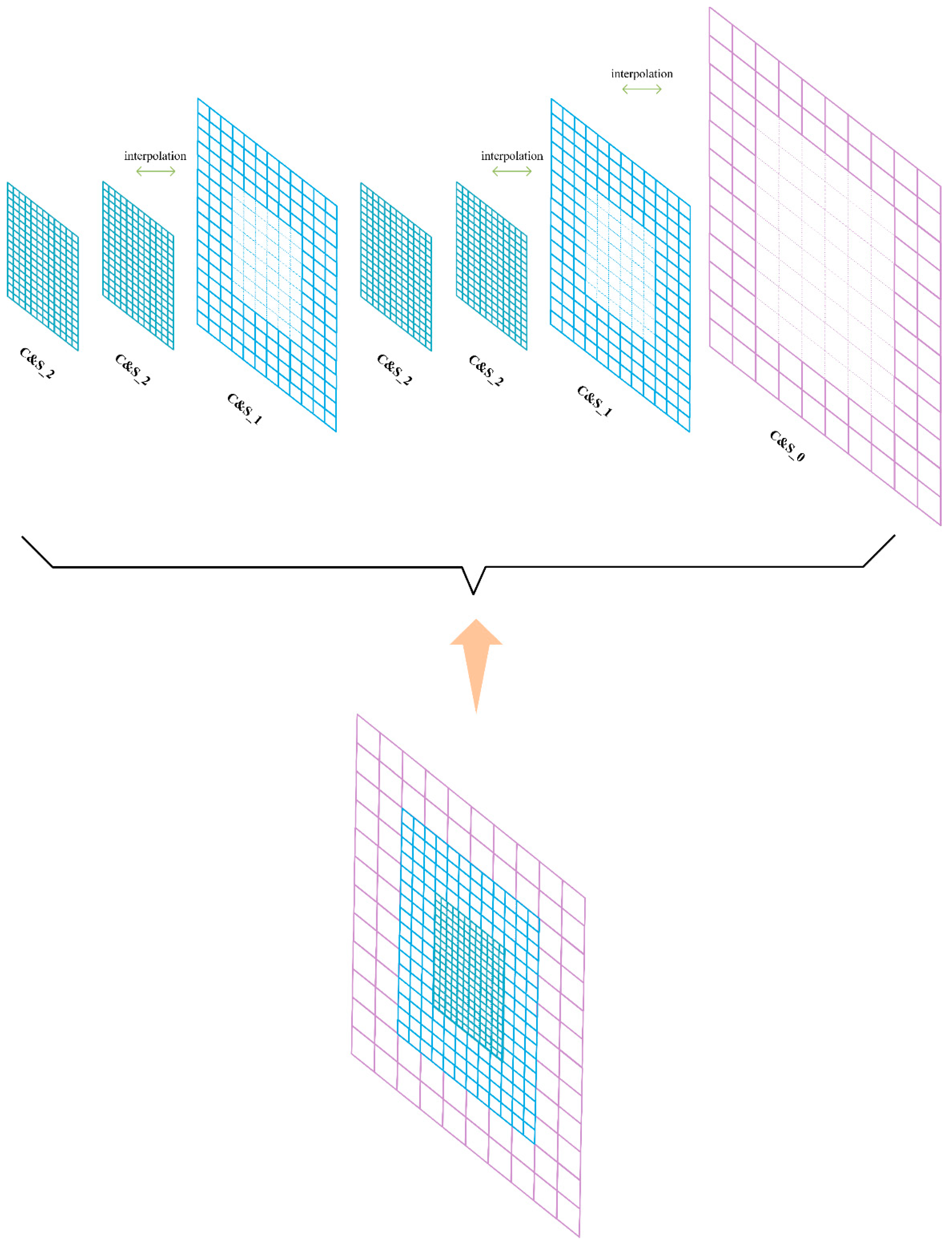
where represents the distribution function from the coarse grid to the fine grid through time and space interpolation. is the time increment ratio between adjacent coarse grids and fine grids. The bar symbol indicates the need for spatial interpolation [49]. The design of the LBM process designed in this paper applying the grid-refinement method is shown in the Figure 4. Its evolution process within one time iteration step uses a loop structure instead of a recursive structure for the programming scheme. Figure 5 shows the evolution of the DC method for the three-layer grid LBM. The code implementation of a multi-layer grid LBM can be based on a geometric subdivision hierarchy of computational domains [41,50]. This structure facilitates the implementation of parallel computing. Based on the experimental content of this study, the hierarchy can be divided from bottom up into the following elements [51]:
Lattice: A geometric point containing distribution function information.
Patch: A set of lattices with the same grid resolution. It constitutes a hierarchy of multi-layer lattices for global tasks or parallel partitioning tasks.
Domain: A set of patches that constitute the global geometric model of the physical simulation.
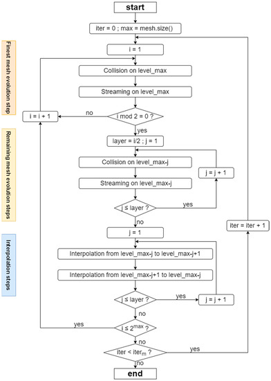
Figure 4.
Flowchart of the DC method. Outside the loop body, the code initializes the variable iteration round to 0 and max is set to the highest grid-refinement level. Within the loop body, the full evolution of one time iteration step is divided into three modules, which are the finest mesh evolution step, remaining mesh evolution steps and interpolation steps. The ordinal number after level_variable represents the refinement level of the current uniform grid. A set of operations on the current grid completes the tasks of a module. Each module schedules the execution of tasks based on the loop control variables and conditional control variables in the flowchart. represents the maximum number of iterations.
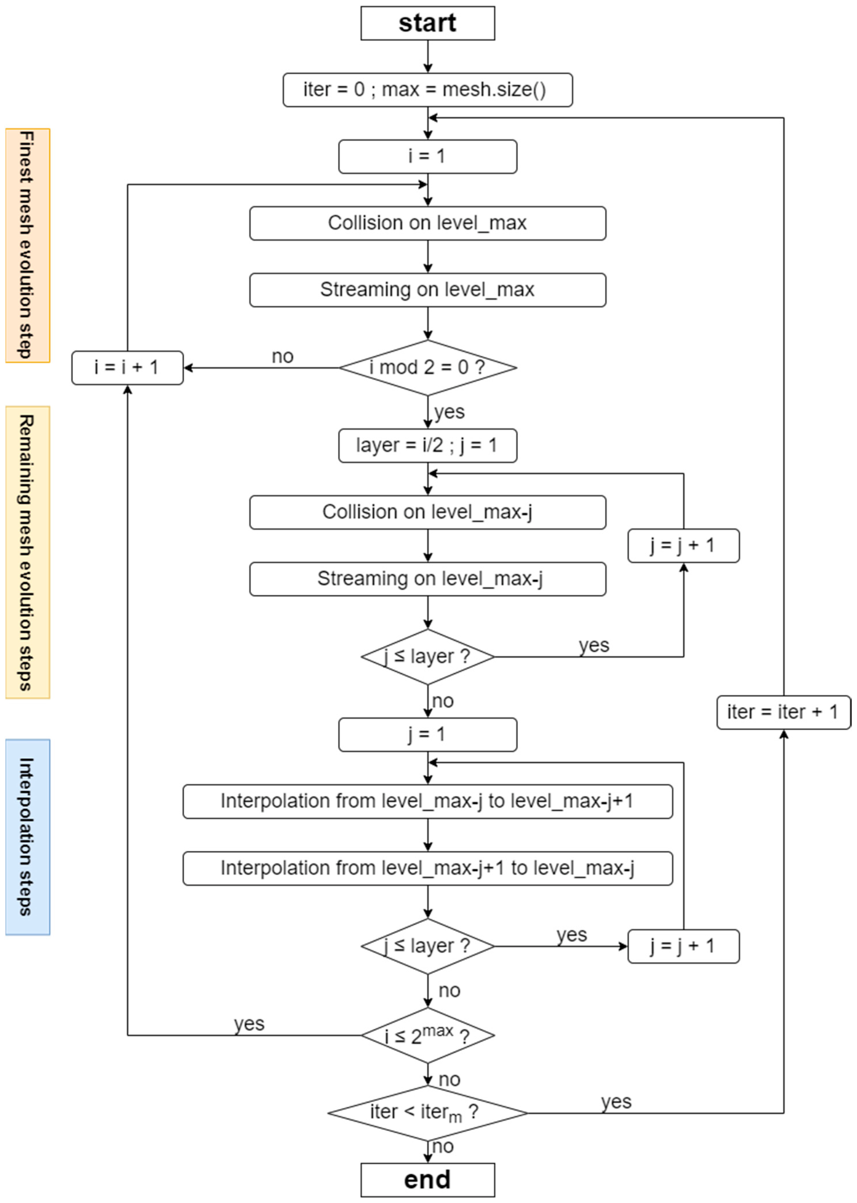
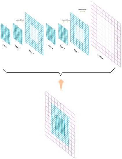
Figure 5.
Schematic diagram of the DC method. “C” is for collision computation, “S” is for streaming computation and “C&S” is for collision and streaming computation. The number after the underscore indicates the grid level. The evolutionary calculation of the domain in one iteration step consists of the collision streaming calculation of different patches. The whole procedure is executed in the regular order shown in the figure.
3. Parallel Strategy and Algorithm
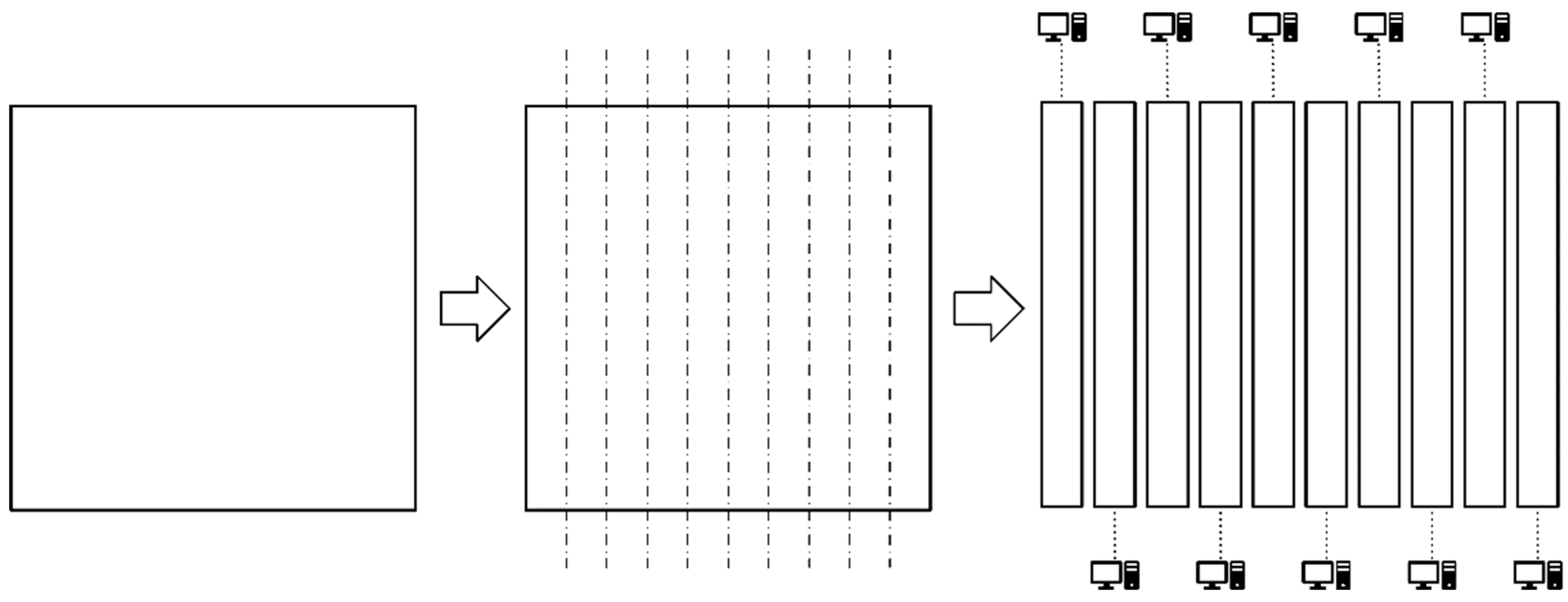
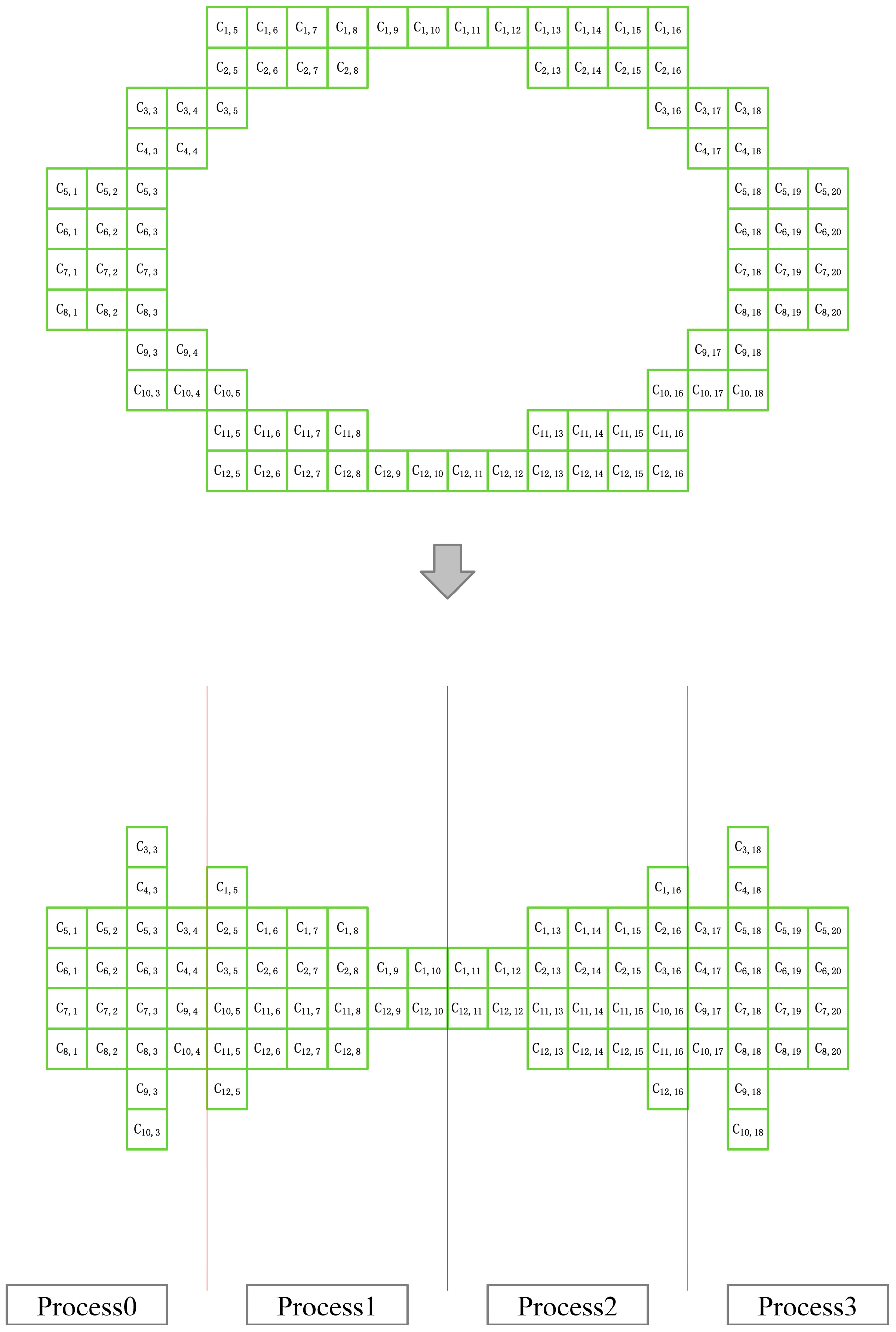
Although the standard LBM has good scalability, the discrete velocity of its particles determines the type of computational grid, i.e., the “lattice” type. In general, this grid has a regular geometry. However, in the calculation, the grid, although simple, lacks flexibility and is difficult to apply to irregular flow fields. The physical quantity of the area changes drastically, and the spatial and temporal gradients are large. Therefore, in this case, it is often necessary to use a local grid-refinement method. The mesh refinement affects the parallelism of the original method. It is necessary to conduct an analysis and design a highly scalable parallel algorithm with load balancing. Load balancing is of great importance in high-performance parallel programming. Load-balanced task allocation is the basis for achieving the highest operational efficiency. In this paper, a static load-balancing scheme is used to construct a parallel algorithm for the multilayer grid LBM. The scheme relies on the grid partitioning scheme shown in Figure 6 to allocate as much load balance as possible for the cluster system in terms of grid computation and memory occupation to achieve shorter running time.
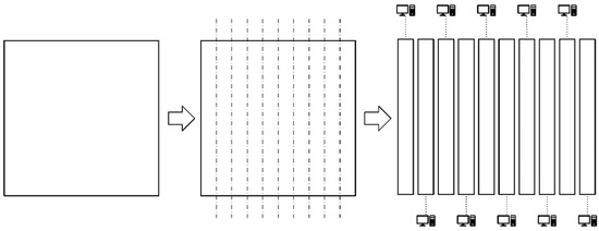
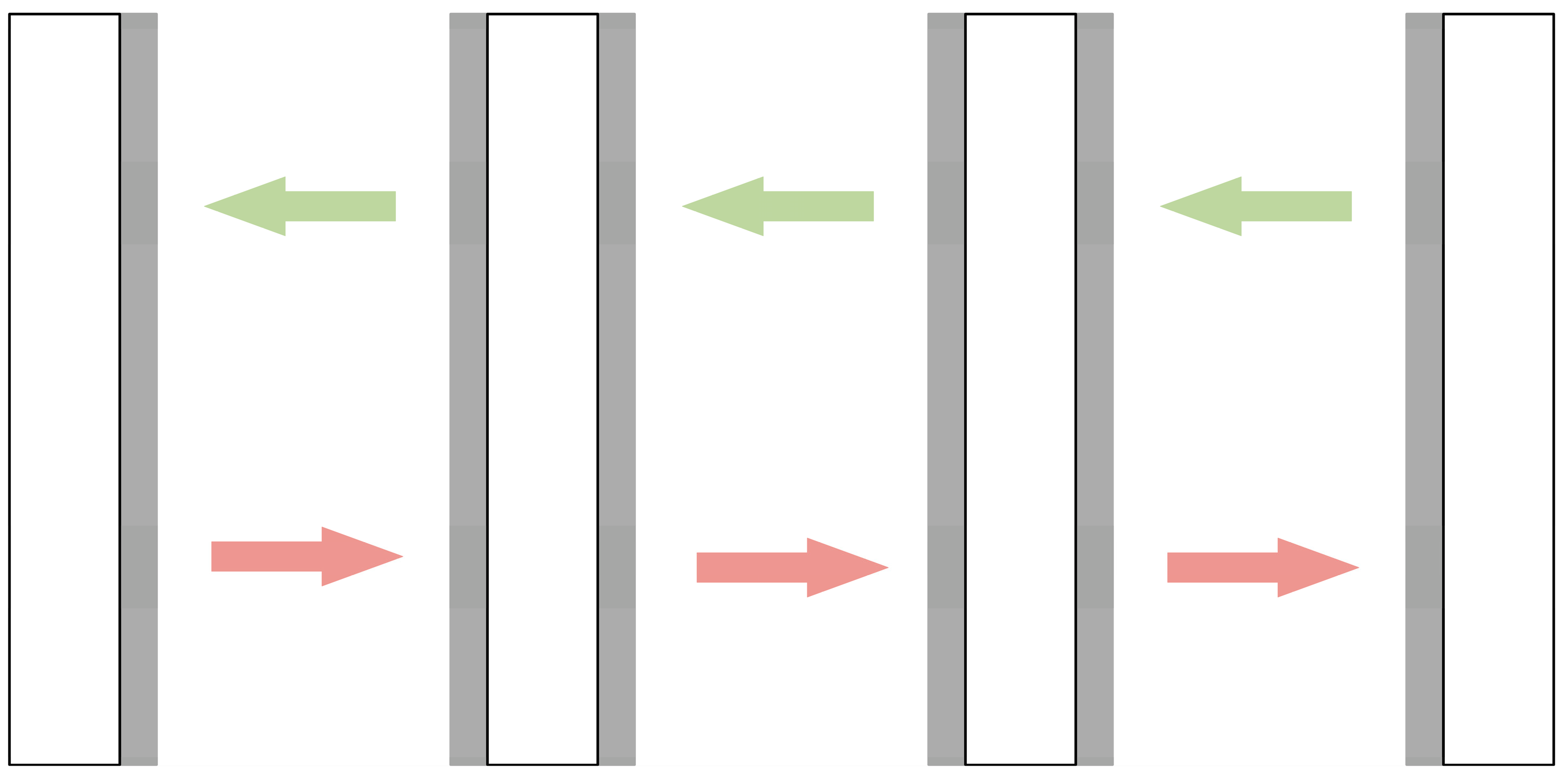
Figure 6.
Parallel division strategy for two-dimensional grids (one-dimensional parallel meshing strategy).
Generally speaking, high-performance computers (or supercomputers) do not necessarily share storage between processors. When developing parallel programs for non-shared storage systems, the various parts of the program communicate by passing messages back and forth. To make the message-transfer method portable, developers need to use a standard message-transfer library. This has led to the emergence of a message-passing interface. This section will start from the perspective of load balancing and combine the characteristics of the multi-layer grid itself to construct a multi-layer grid LBM parallel algorithm based on MPI and test its parallel efficiency to verify the scalability of the parallel algorithm.
3.1. Meshing Strategy Based on Load Balancing
Before giving a specific MPI parallel strategy, it is necessary to understand the MPI parallel algorithm of the standard LBM, especially the data transfer between nodes. Here this paper first introduces the MPI meshing in a two-dimensional case. Distributing the workload evenly to all available processes is essential for good scalability and high performance. The goal is to prevent processes from being idle while waiting for data from other processes. All grid cells in the simulation space are allocated to all available processes so that there are no idle processes during execution. This is the central task of the load-balancing algorithm [28]. In this paper, a similar one-dimensional meshing strategy is used for the meshing phase of the numerical simulation parallel test, which is shown in Figure 6.
In the absence of grid refinement, assigning all grid cells based on weights is a very suitable load-balancing strategy for LBM-based simulations. However, for the parallel LBM on a non-uniform grid, it is not feasible to divide the parallel computing domain perfectly according to the weight of the grid unit. Here, patches at different levels cannot be processed completely independently. Patches of various levels must communicate with one another through communication from fine grids to coarse grids and from coarse grids to fine grids during the algorithm’s fixed stage. A suitable load-balancing strategy must consider the algorithm structure, including all communication points, in order to achieve the greatest performance.
The simulation space of various grid cell refinement levels is taken into consideration as the load-balancing strategy that works well for the multi-layer grid LBM algorithm. For each level of grid space, all grid cells on that level are allocated to processes available in the computer system. Previous works have discovered during the experiment that the finest grid level has the largest workload. Therefore, efficiently distributing the work generated by the finest grid level is essential to maximize performance. Different load-balancing algorithms can be applied to the grid space at each level. However, the meshing algorithms designed above are all used in the actual experiments. In a two-dimensional simulation case, the grid space at each level is mapped to a one-dimensional array storing the number of grids involved in the evolutionary steps for each column of the stripe-shaped 2D grid region. In the case of a 3D simulation, each level of the grid space is mapped to a one-dimensional array storing the number of grids involved in the evolution steps for each column of the face-shaped 3D grid region. This one-dimensional array is sequentially divided into parts that are roughly equally divided ( is the number of available processes) and reflected in the grid space, which is the composition of np grid spaces divided by columns. Finally, the grid parts at all levels allocated to each process are combined to form the final parallel LBM computing domains. As a result, this division method can effectively compress the idle time of the process. It is clearly concluded that this load-balancing scheme is completely suitable for the LBM parallel algorithm on a non-uniform grid. For simulation problems on arbitrary uniform Cartesian grid regions, the meshing scheme shown in Figure 6 is worth trying. This article cleverly separates the grid in one dimension at each resolution level when applied to the computing problems of multi-layer grid LBM. The process numbers are sequentially assigned to the sub-domains of the divided regions in one direction on the multilayer grid structure. On the multilayer grid structure, the process numbers are sequentially assigned to the sub-domains of the separated areas in one direction. The sub-domains with the same process number at different levels are finally assembled into independent computational regions under one process space. In this model, MPI communication between different process spaces is simple and straightforward. Most of the data exchange between boundary grids occurs only between adjacent process spaces in the horizontal direction, avoiding possible performance loss and communication blockage due to complex communication, and overall maintaining the performance advantage brought by parallel algorithms designed for one-dimensional partitioning on uniform grids, which was be verified in subsequent performance evaluation experiments.
For the multi-layer grid LBM program, the meshing algorithm this paper designed is as follows (see Algorithm 1):
| Algorithm 1 Multi-layer grid-meshing algorithm based on load balancing |
| Input: computational grid (number of grid layers: N, each layer of grid is denoted as k); number of processes set in parallel environment np; |
| Output: result of computational domain’s meshing; |
|
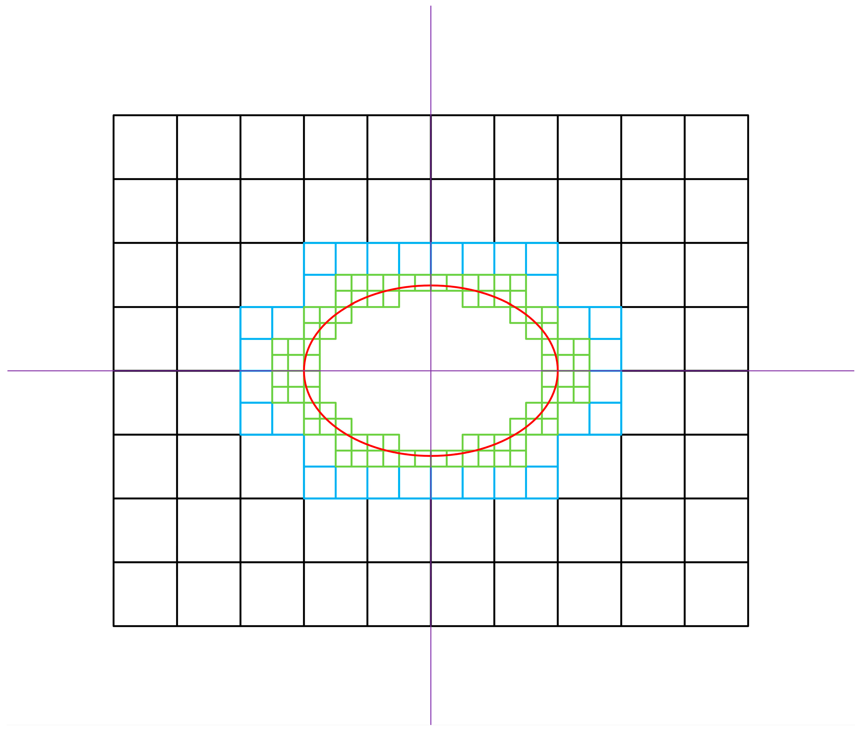
In this paper, the MPI data-transfer method based on the load-balanced grid parallel-meshing strategy for the case of partitioning a two-dimensional grid is shown in Figure 7. It can be seen from Figure 7 that the one-dimensional MPI data-transmission method is relatively simple, where mainly the interface data needs to be transmitted, and the corresponding data is transmitted to the corresponding sub-domain. Since it is a one-dimensional division, the transfer direction is only in the left and right directions. After understanding the traditional LBM meshing scheme and data-transfer method, this paper studies the complete parallel scheme for the multi-layer grid LBM. For the convenience of drawing and text description, this paper uses a two-dimensional elliptical cylinder as a calculation example, and uses three layers of fine meshes for discussion, as shown in Figure 8. According to the content of the second section, the calculation amount of each grid point on the same layer of the multi-layer grid LBM method is basically the same. The interpolation calculation at the boundary of the coarse and fine grids is not considered. For example, the calculation amount of the grid points in the first layer of the grid is 1/2 times the calculation amount of the grid points in the second layer of the grid. The grid points in the second level grid are 1/2 times the calculation amount of the grid points in the third level grid.
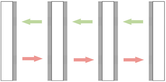
Figure 7.
MPI data-transfer method in the case of two-dimensional grids. The shaded part represents the data to be transmitted and received and represents the spatial position of the sub-domain in the two-dimensional space.
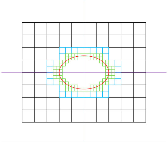
Figure 8.
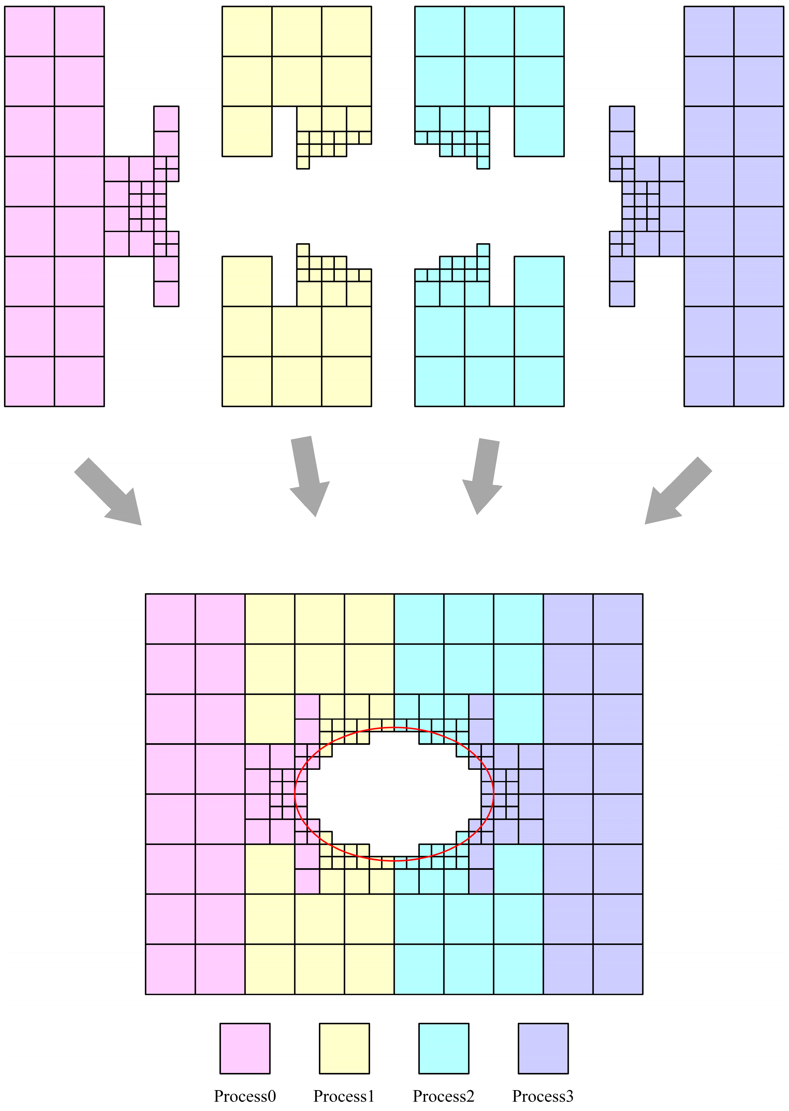
Example of a three-layer grid: the grid with a black frame is the first grid, the grid with a blue frame is the second grid and the grid with a green frame is the third grid. The red ellipse circle indicates the solid boundary in the flow field.
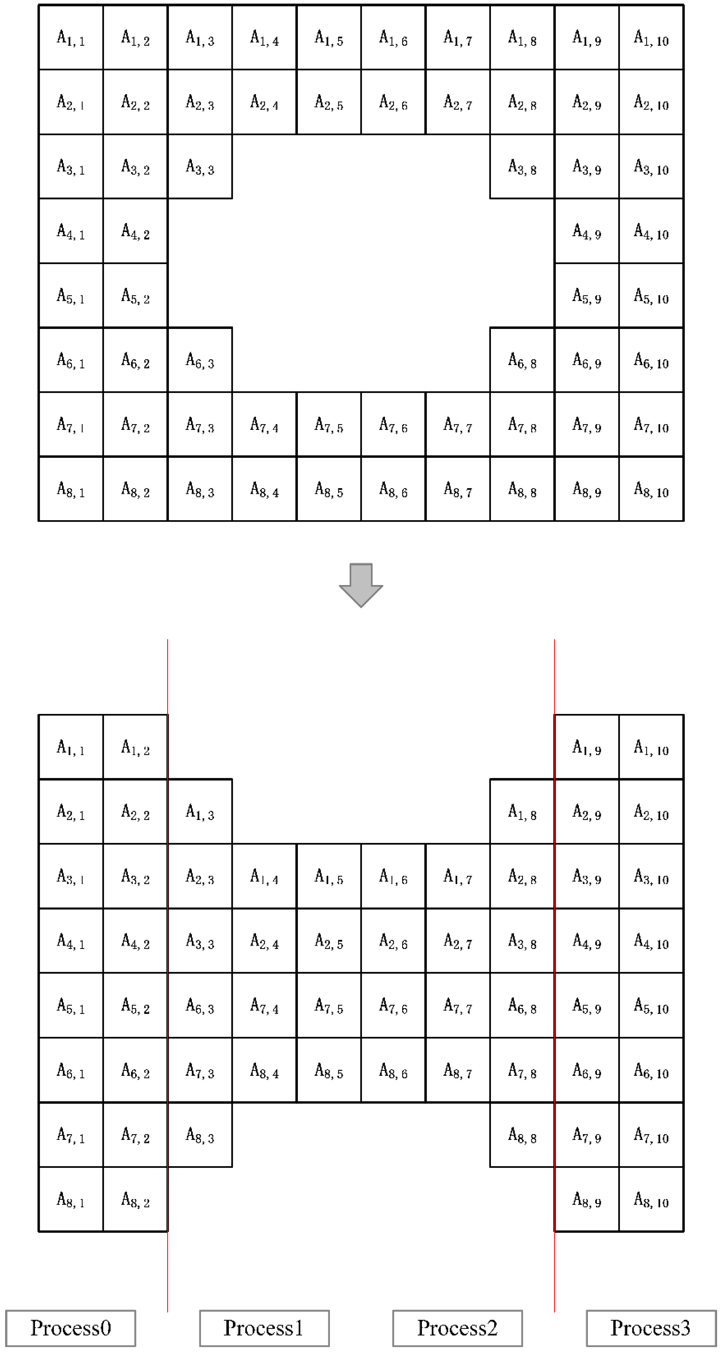
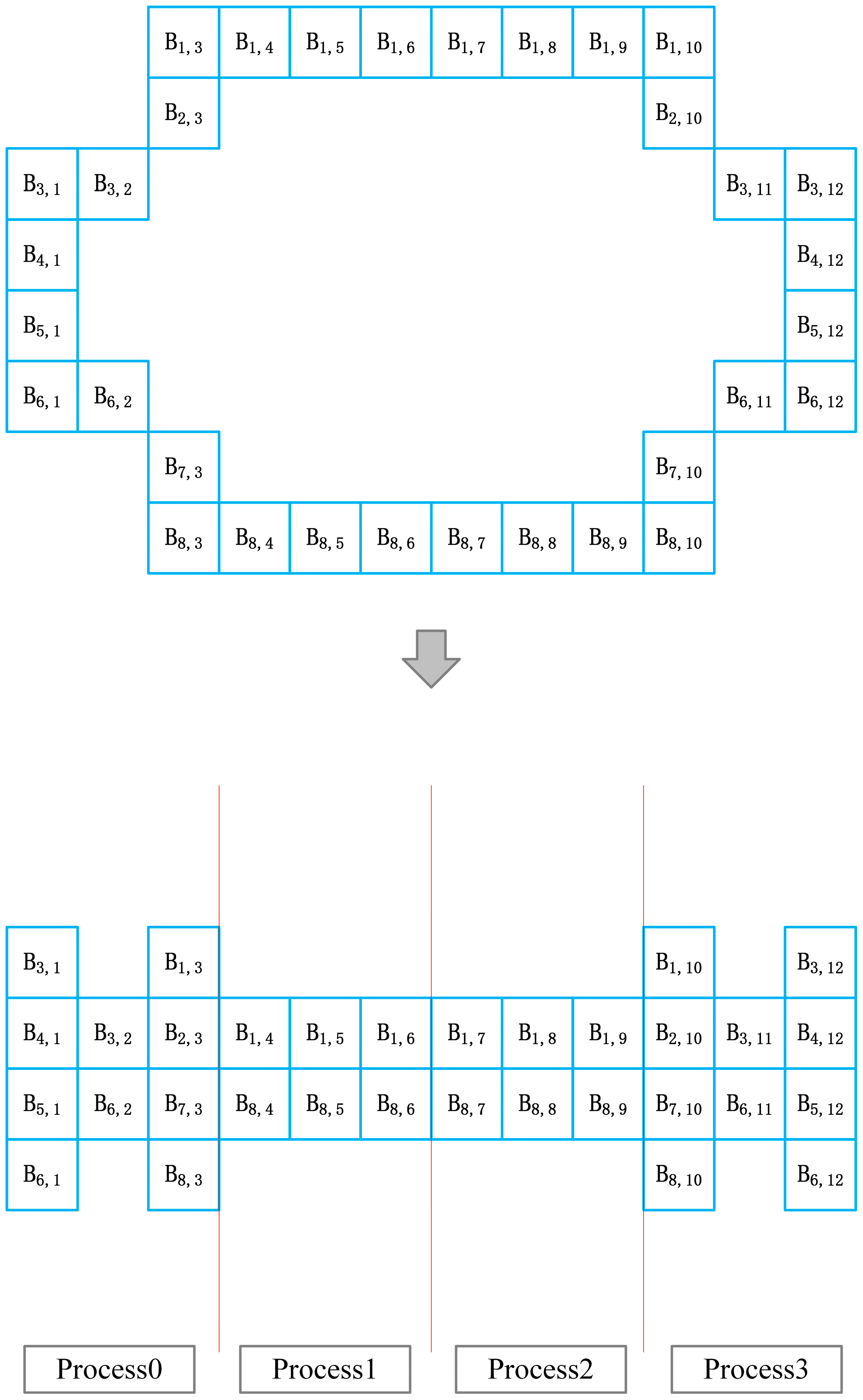
Based on the idea that each grid point on the same layer of the grid has essentially the same amount of computation, the scheme performs parallel meshing. The whole grid in Figure 8 will be divided into three meshes with different resolutions. The first layer of the grid in Figure 8 is analyzed and labeled on the grid points, as shown in Figure 9. The same partitioning idea is used for the second and third layers of the grid of the parallel algorithm. The detailed partitioning is shown in Figure 10 and Figure 11.
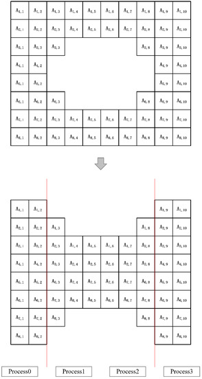
Figure 9.
There is a total of 60 grid points in the first layer of grid, so assuming that the number of processes of MPI is 4, each process should normally be divided into 15 grid points. However, for the convenience of description, a one-dimensional division method is used on the single-layer grid here. According to the first-layer grid structure in Figure 8, it can be divided into 4 patches, and the left and right patches are 16 grids. The two patches are 14 grids, so the number of grid points processed by each process can be basically kept the same.
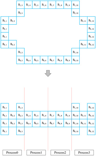
Figure 10.
The 32 grid points in the second layer grid are divided into one dimension, and the number of grid points allocated to the 4 MPI processes are 10, 6, 6 and 10, respectively.
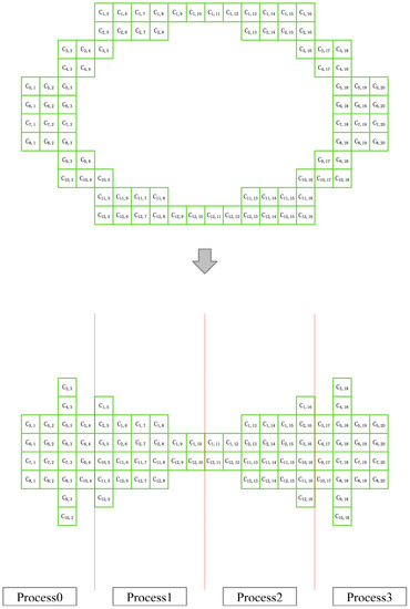
Figure 11.
The 84 grid points in the third layer of the grid are divided into one dimension, and the number of grid points allocated to the 4 MPI processes are 20, 22, 22, and 20.
According to the grid-division method described above, the grid from the first layer to the third layer is basically evenly divided into 4 equal parts. Each MPI process can be responsible for a part of each layer of the grid. The algorithm defines the process numbers of the four MPI processes as 0, 1, 2 and 3. Then, the computational grid responsible for a single process of these four MPI processes is shown in Figure 12.
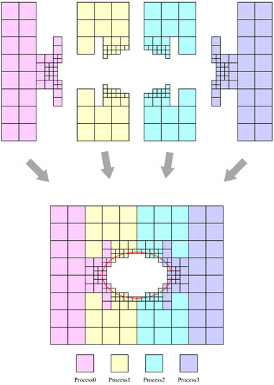
Figure 12.
MPI parallel strategy: red represents process 0, yellow represents process 1, blue represents process 2 and purple represents process 3. The red ellipse circle indicates the solid boundary in the flow field.
3.2. Multi-Layer Grid LBM Parallel Algorithm
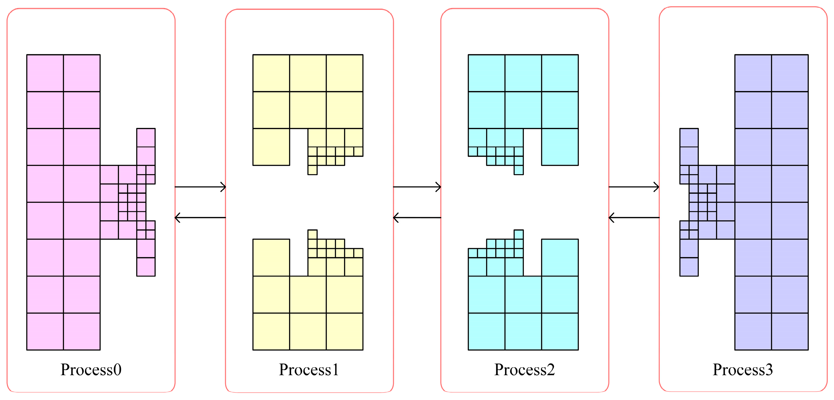
The multi-layer grid LBM parallel strategy and data-transmission method based on this parallel division is shown in Figure 13. In this MPI parallel strategy, each computational node only needs to transmit data with two adjacent nodes. Therefore, the parallel strategy is theoretically scalable.
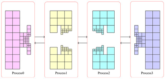
Figure 13.
Multi-layer grid LBM parallel strategy and data-transfer method.
It should be noted here that MPI data transmission needs to be carried out in each layer of grid computing in order to reduce the number of communications of MPI in the case that grid size is small enough. It is possible to initialize only the data at the intersection of the mesh in the first layer of the grid. For the data in the second- and third-layer grids, it needs to be obtained by interpolation in time and space, which will lead to the accumulation of numerical errors. Therefore, the specific MPI parallel strategy and the details of the strategy should be discussed according to the specific situation of the problem. The parallel algorithm designed in this paper is built on the computational domain space handled by the one-dimensional meshing algorithm. Evolutionary data and interpolation data are divided from the data in the junction portion of the grid division. Evolutionary data is used to complete the evolutionary step by passing data from the junction part of the computational domain of the same grid level in different process spaces, expressed as all or part of the lattice on the outermost vertical column of the grid at each level. The interpolation data is used to complete the interpolation step between the coarse and fine grids. It does not have to be the entire data of the junction part of the coarse and fine grids, but the junction part of the computational domains at adjacent grid levels in different process spaces. The interpolation data is specifically represented as a collection of lattice segments in the buffer section for interpolation processing between two levels of grids. The coarse mesh on this buffer is not in the same computational resource as several of the fine meshes in the coarse mesh. The junction part of the multi-layer grid is complex in appearance but only needs to complete the data transfer between these two parts to be processed in parallel. Both the evolutionary and interpolation data contain the necessary distribution function information as well as the neighboring grid information. Evolutionary data accounts for most of the communication traffic and affects the MPI parallel performance, sending and receiving only in the adjacent process space. The amount of interpolated data traffic is determined by the grid structure. Under reasonable circumstances it is a very small amount of communication, but it is a necessary part of the interpolation calculation. It affects the experimental accuracy and can be communicated in different process spaces. Peer-to-peer MPI communication uses the aforementioned data. The MPI blocking function interface, which is used for parallel processing, necessitates caution to prevent deadlocks.
This section gives the corresponding multi-layer grid LBM parallel algorithm based on the MPI grid-division parallel strategy in Section 3.1, see Algorithm 2. The main steps of the message-passing LBM implementation need to pay attention to the following points:
- Data partitioning: Try to consider the load-balancing grid partitioning methods to achieve the goal of the balanced use of storage space and fewer communications between processors. Decompose the entire computational domain into several computational sub-domains with as regular shapes as possible and map the boundary conditions and initial conditions of each sub-domain to each computing node in the parallel environment.
- Separate calculation: For the node to which each computing area belongs, calculate the flow and collision substeps of fluid particles on the grids inside the region, and calculate the macroscopic physical quantity.
- Optimize communication: Each computing node conducts data exchange and information transfer on the intersection boundary with its neighboring nodes through certain coupling rules to organize parallel computing and maximize the computing communication ratio.
- Global operation: Combine the local results of each processor to achieve the final solution of the entire original problem.
| Algorithm 2 Multi-layer grid LBM parallel algorithm based on MPI |
| Input: computational grid (number of grid layers: N, Each layer of grid is denoted as k); Initial information of the flow field (density, speed, pressure, Reynolds number, etc.); Output: flow field calculation results;
|
4. Numerical Simulations
In this section, the experiments provided two numerical validation scenarios, namely elliptical cylindrical bypass and spherical bypass simulations, respectively. They were used to confirm the accuracy and stability of the multi-layer grid LBM designed in this thesis and also its parallel numerical method for 2D and 3D unstructured grid computational problems.
4.1. Flow Past an Elliptical Cylinder in Two-Dimensional
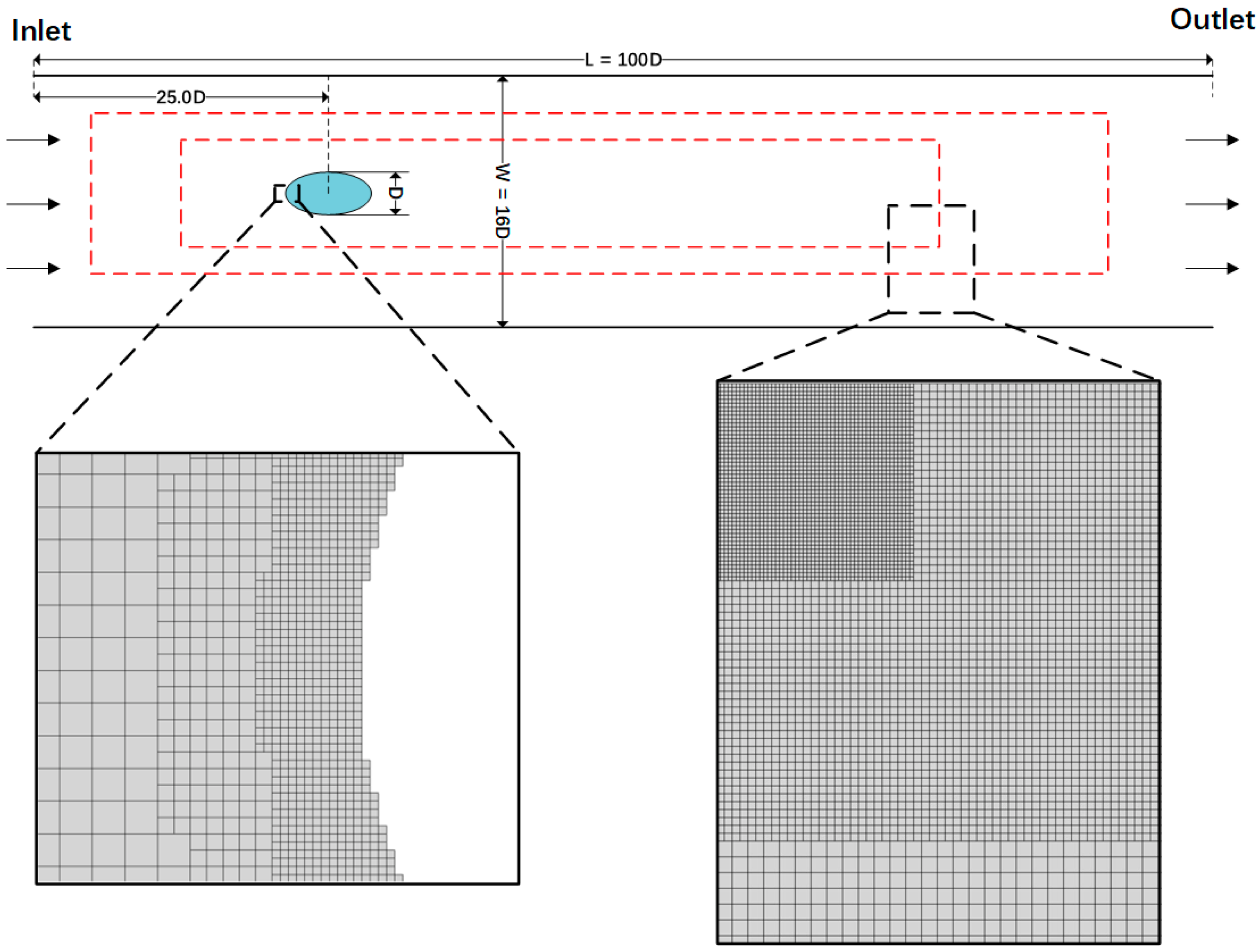
Cylindrical flow is a classical benchmark problem. In order to study more complex geometries, the validation experiments investigated the flow field properties and vortex structure in incompressible flows with two-dimensional elliptical cylinders at zero angle of attack using the LBM. There is a column with an elliptical cross section (long axis was set to , short axis set to and the long axis was parallel to the channel and the water flow) in the simulation scenario. The column was mounted in a vertical position, centered on a flat channel with a width of . The length of the planar channel was fixed at and the upstream length was chosen as . The Reynolds number was defined as , where is the inlet velocity of the channel, and the geometric structure and coordinate system of the flow field region are shown in Figure 14. The experimental work on the multi-layered grid structure used the following settings: two layers of local grid refinement of the enclosing box were added to capture the detailed wake structure, and a multi-layer of cell grids with local grid refinement was extrapolated to the boundary grid near the elliptical cylindrical structure to capture the flow field characteristics of the solid surface. The outermost lattice size was set to .
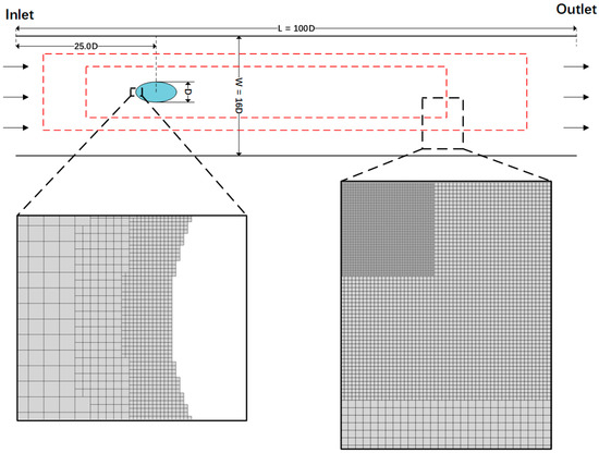
Figure 14.
Diagram of the flow through the elliptical cylinder restrained in the channel. The red dashed lines indicate two regions of local mesh thinning within the enclosing box. The enlarged view on the right shows the localized detail at different resolutions in the three enclosing boxes. The enlarged view on the left shows the details of the local mesh refinement of the fitting mesh at the boundary of the elliptical cross section.
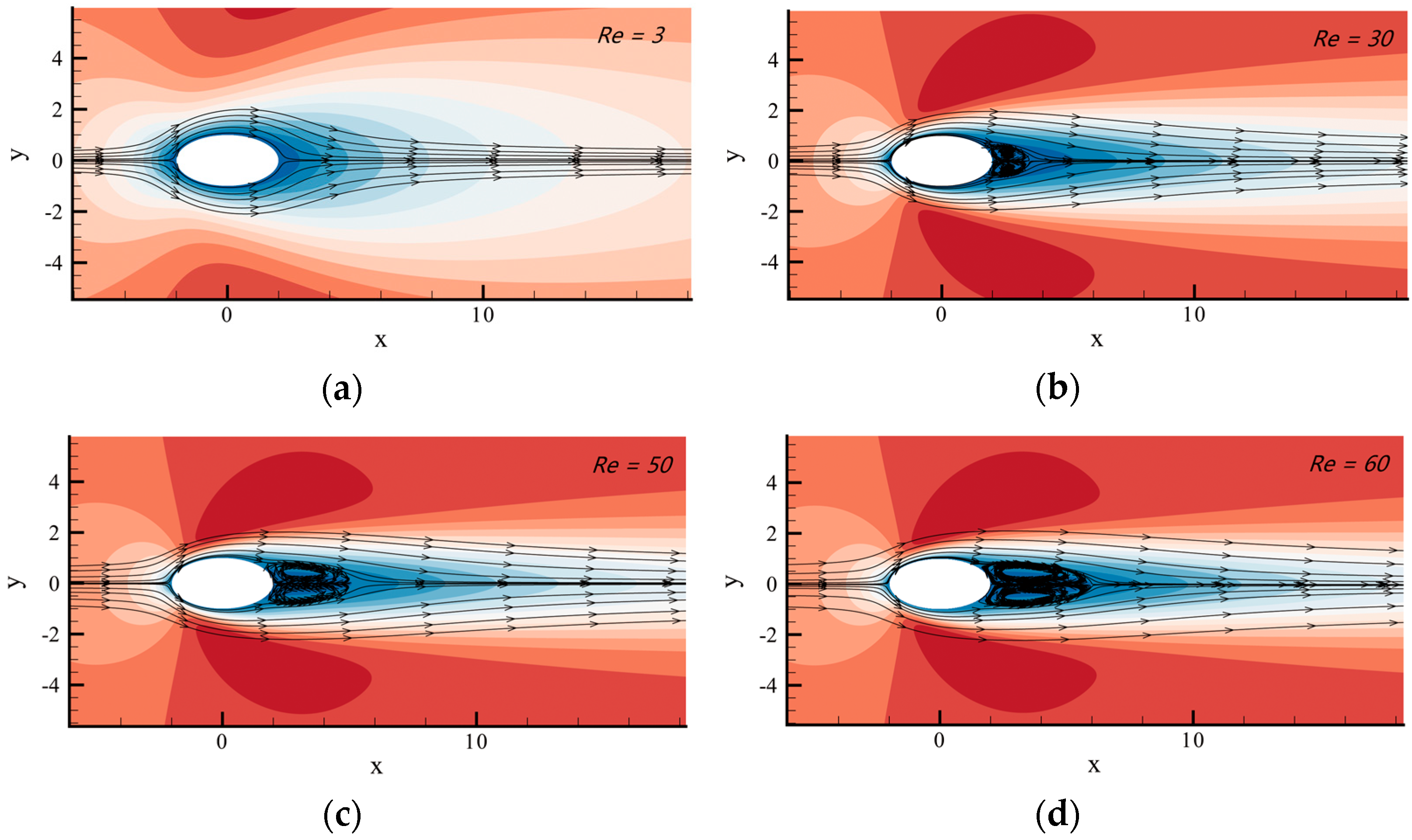
The experimental work investigated the experimental phenomena of elliptical cylinders at different Reynolds numbers for a fixed blockage ratio. Firstly, the steady flow state of elliptical cylindrical bypass flow at low Reynolds numbers (see Figure 15) was experimentally investigated.
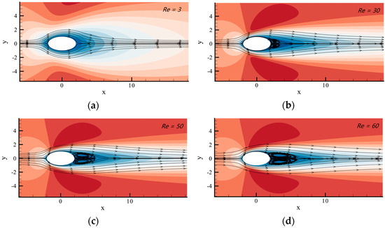
Figure 15.
Steady flow line diagrams through elliptical cylinders at different Reynolds numbers. (a–d) correspond to the Reynolds number 3, 30, 50 and 60, respectively.
The continuous flow through the rigid body continued in the case of without separating. When the Reynolds number was between 30 and 60, the steady flow laminar flow appeared to be separated, while the two vortices downstream of the column continued to be symmetrically spaced and attached to the column. In addition, as the Reynolds number rose, the vortex size also kept growing. In this work, the length of the recirculation layer along the horizontal centerline of the steady flow was experimentally determined at various low Reynolds numbers, and the results were found to be in agreement with D. Arumuga Perumal’s previous research [52], as shown in Table 1.

Table 1.
For four Reynolds values, the length of the recirculation area was measured. The measured length of the recirculation layer divided by D is used to express the length data here.
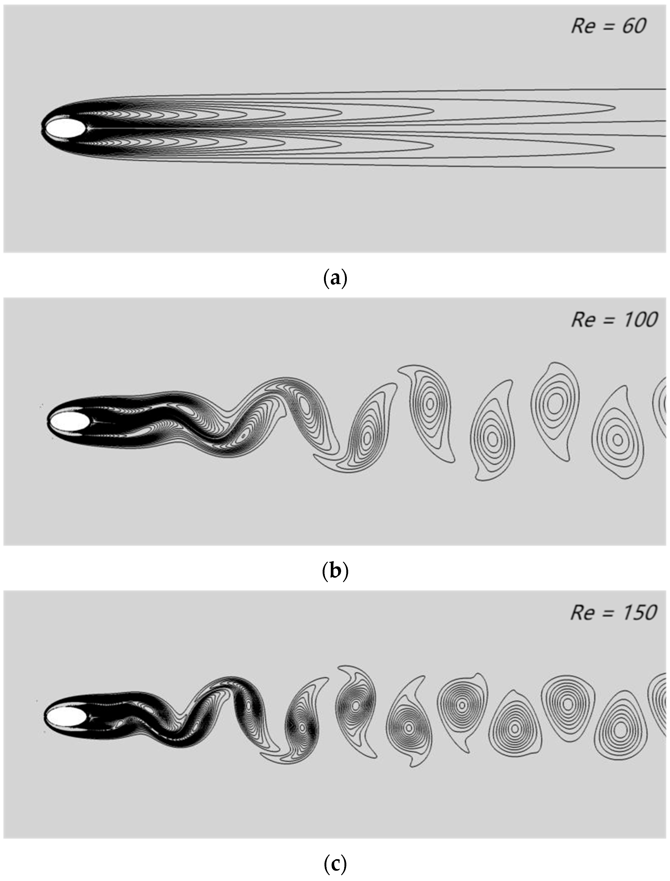
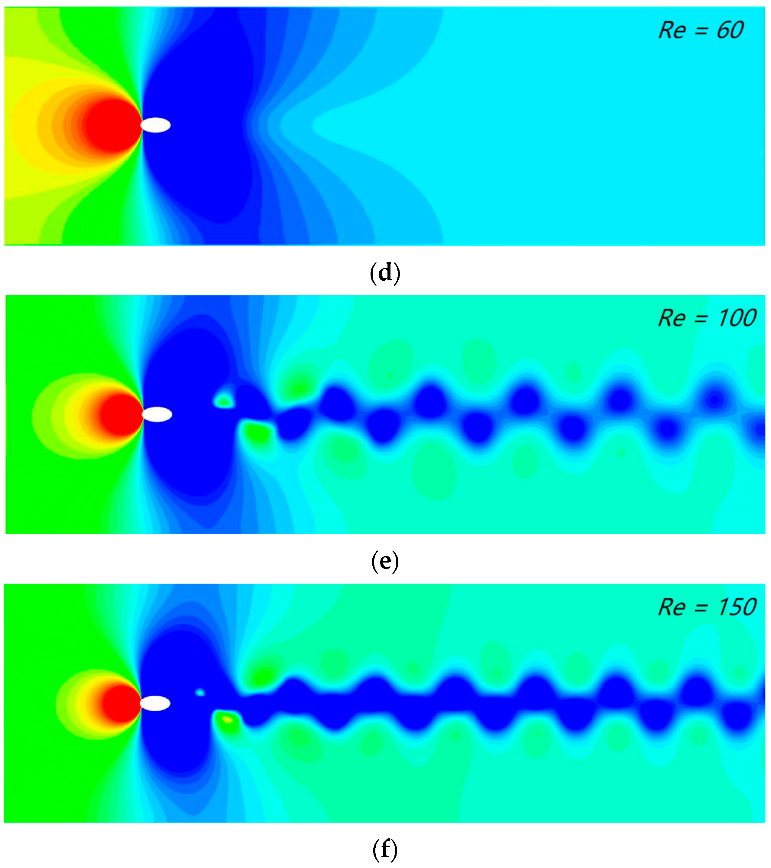
Figure 16 depicts the vorticity contours and pressure contours of incompressible flow through an elliptical cylinder at different Reynolds numbers (Re = 60, 100 and 150). The alternate shedding of vortices in the wake region could be clearly found, and periodic vortex shedding grew with increasing Reynolds number. These experimental phenomena were in agreement with the experimental results of D. Arumuga Perumal.
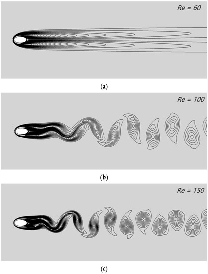
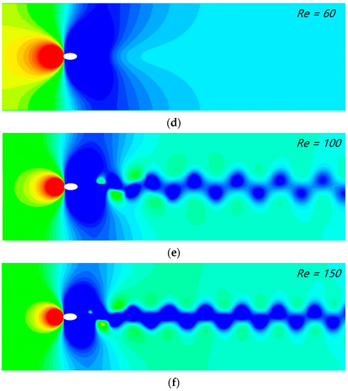
Figure 16.
Instantaneous vorticity contours surrounding the elliptical cylinder at various Reynolds numbers: (a) Re = 60, (b) Re = 100 and (c) Re = 150; instantaneous pressure contours surrounding the elliptical cylinder at various Reynolds numbers: (d) Re = 60, (e) Re = 100 and (f) Re = 150.
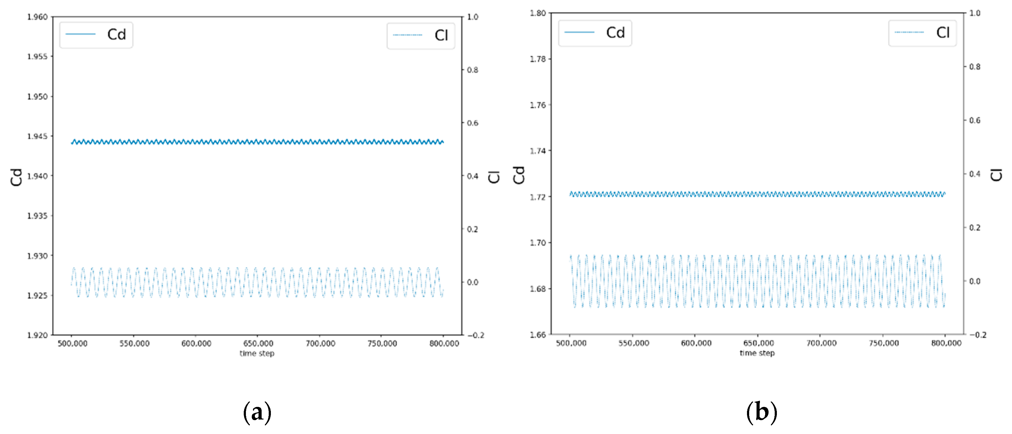
Figure 17 illustrates the cyclical variation in the lift coefficient and drag coefficient with time iteration steps for the fluid flowing through the elliptical cylinder at Re = 100 and 150. The average drag coefficient for the two Reynolds number cases was obtained from the experimental records and compared with previous experimental studies. Table 2 shows the results of the comparison, and it can be concluded that the drag coefficient decreased with increasing the Reynolds number. In addition, our multi-layer grid numerical method was accurate and stable.
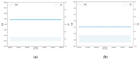
Figure 17.
Elliptical cylindrical bypass: lift and drag coefficients (Cl and Cd) when (a) Re = 100 and (b) Re = 150.

Table 2.
Average drag coefficients for elliptical cylindrical bypass flow at different Reynolds numbers, and comparison with previous studies.
4.2. Flow Past a Sphere in Three-Dimensional
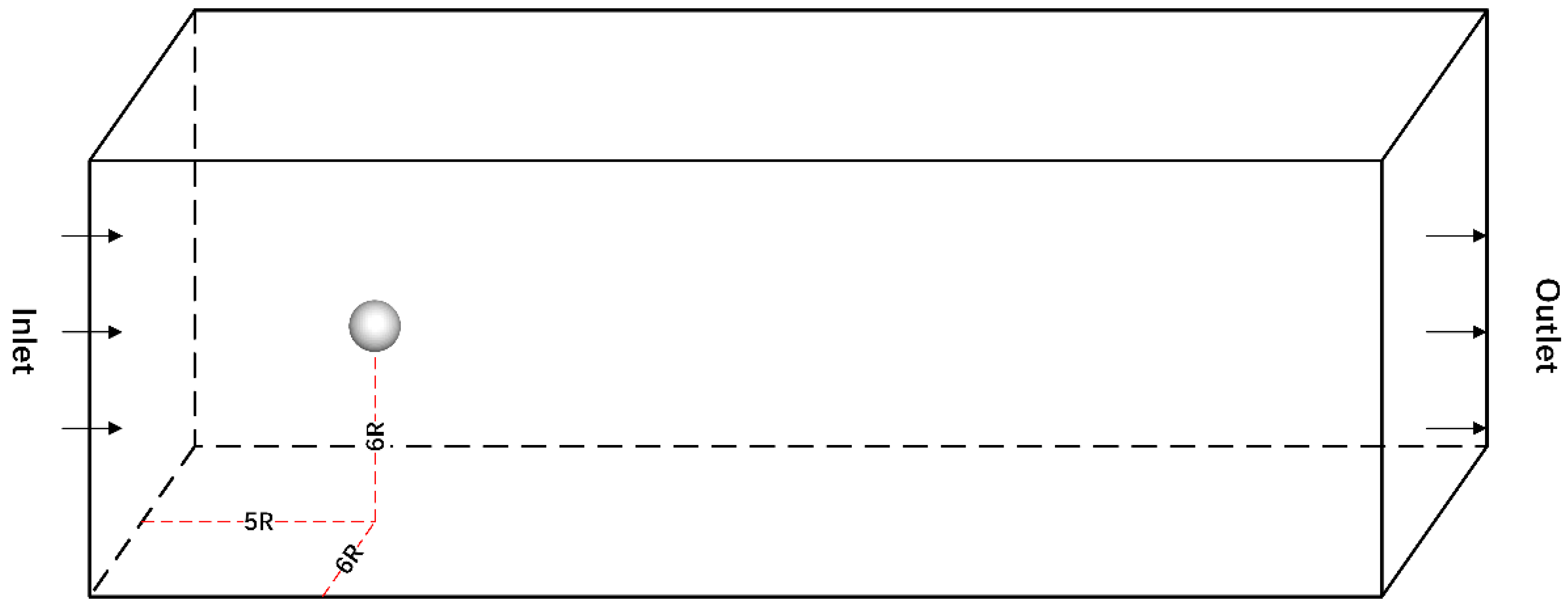
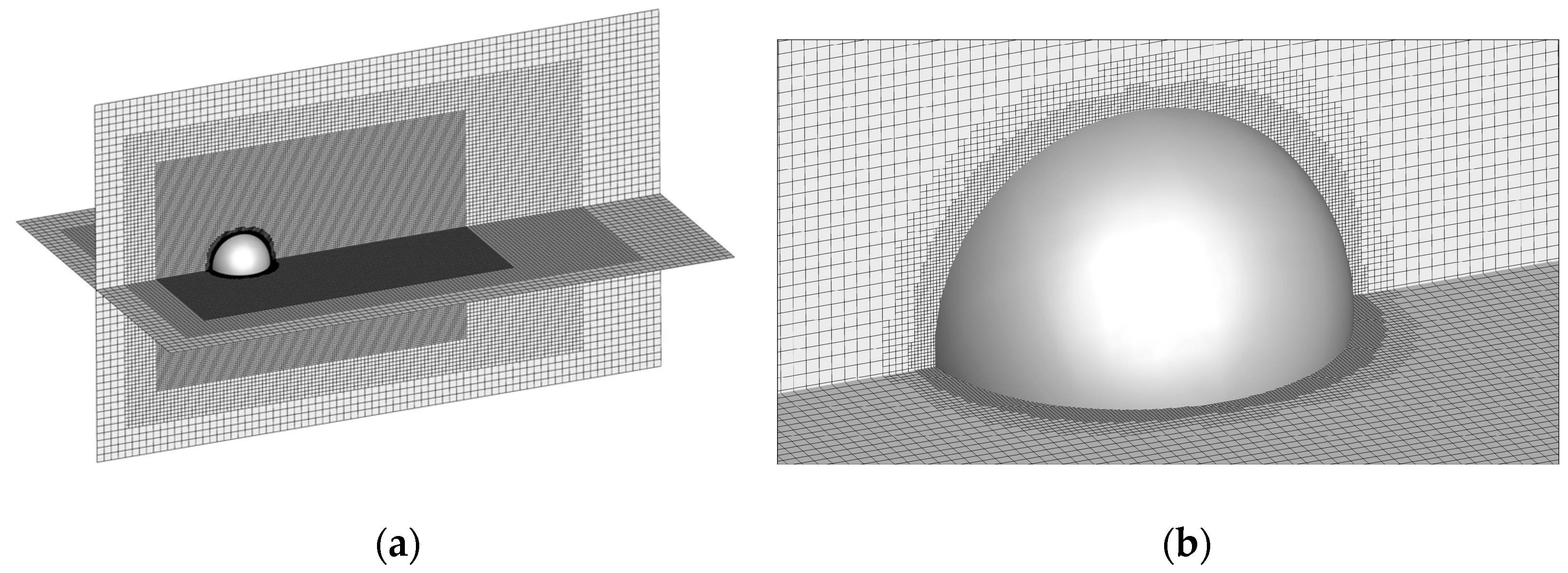
The experiment applied a multi-layer grid in a flow field calculation domain, with an incompressible flow through a rigid sphere of constant flow calculation. The specific geometric numerical quantities were as follows: the radius of the sphere was R, the cross-section of the computational domain was a square of , the length of the computational domain was and the center of the sphere was fixed at the center of the cross-section upstream of the flow field. The regional geometric structure shape and coordinate system of the 3D sphere around the flow are shown in Figure 18. The multi-layer grid structure experiment was set up to surround the sphere as well as the three-layer local grid refinement surrounding box in the downstream region of the sphere. The flow field region at the boundary of the sphere was set up with two rounds of six-layer local grid refinement to capture the accurate simulation. The grid structure is shown in Figure 19.
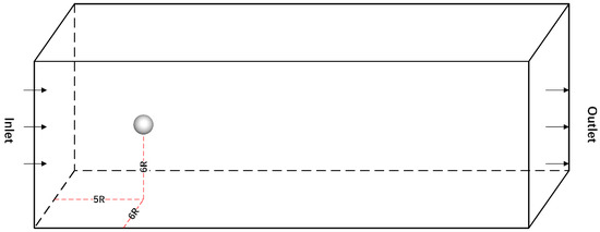
Figure 18.
Geometry diagram shows the coordinate system and computational domain of the sphere around the flow in three dimensions.
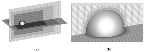
Figure 19.
(a) shows the multi-layer grid structure of the sphere around the flow in 3D, with the global grid structure of the computational domain and (b) displays the local grid refinement around the boundary of the spherical rigid body on the right.
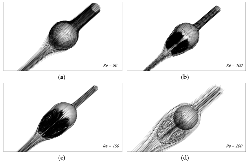
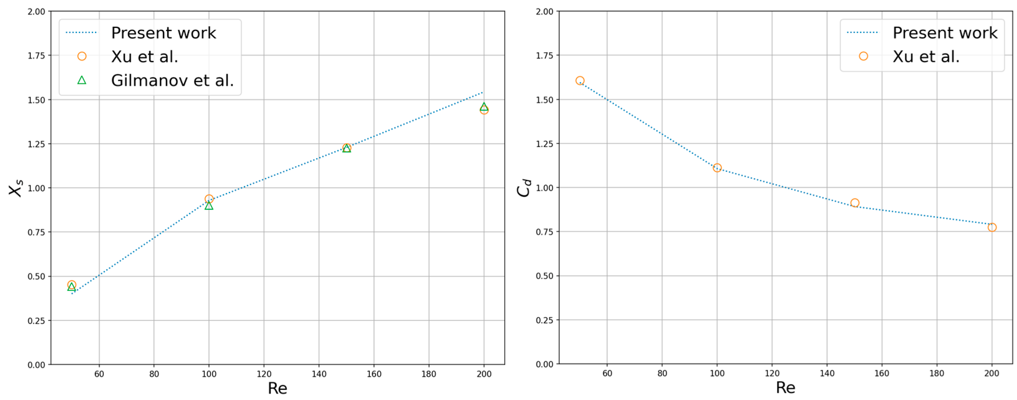
Four sets of steady axisymmetric flow simulations with different low Reynolds numbers were carried out, and the Reynolds number was defined as: . Figure 20 shows the streamline diagram of the flow-pass sphere in the 3D flow field. For the details of the flow geometry and mechanical properties, the length of the recirculation region and the drag coefficient were selected to compare the simulation results with the previous results of A. Gilmanov et al. [53] and Lei Xu et al. [54] who adopted a general reconstruction algorithm with complex 3D immersed boundaries on Cartesian grids and a scalable parallel unstructured finite-volume LBM, respectively (see Figure 21). It can be concluded that as the Reynolds number increased, the recirculation region volume became larger, and the drag coefficient decreased. Extending to numerical tools for solving various fluid flow and heat transfer systems, the parallel scheme was expected to provide high performance in handling simulation scenarios including nanofluids, energy storage devices, as well as systems with electro-thermo convection. The drag coefficient is defined as:
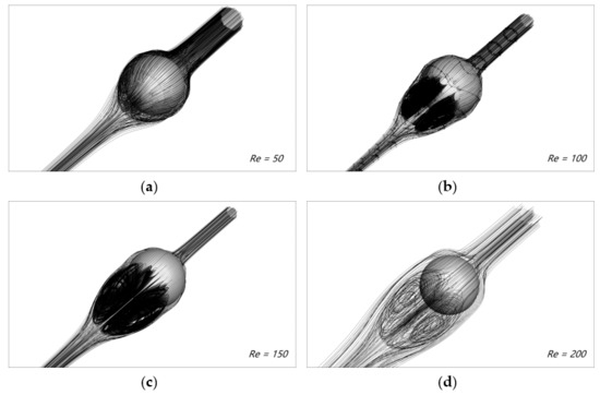
Figure 20.
Streamlines of the flow field of a three-dimensional sphere at different Reynolds numbers. (a) Re = 50; (b) Re = 100; (c) Re = 150 and (d) Re = 200.
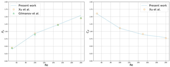
Figure 21.
Flow geometry and drag coefficient affected at different Reynolds numbers [53,54].
5. Performance Evaluation
In addition to the scalability performance tests. The parallel performance evaluation experiments on a non-uniform multilayer grid LBM also needed to focus on the communication behavior of the interpolated data transfer between different levels of the grid during its parallel computation and design different test scenarios. The results were used to evaluate the performance help of the parallel algorithm given in the paper for the multi-layer grid LBM. Such an idea is suitable to be applied to most parallelism studies of the multi-layer non-uniform grid numerical methods. This is a seminal element and an important part of the performance evaluation phase of this thesis.
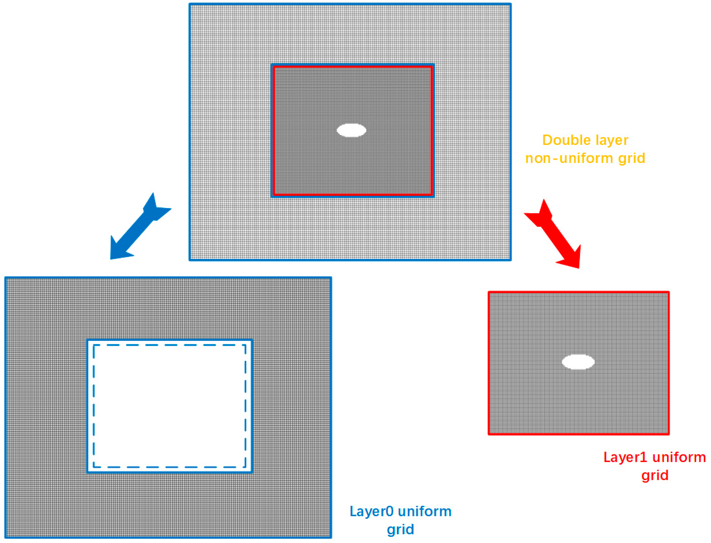
This paper first compared the performance of uniform and non-uniform meshes in terms of parallel performance. The experimental design differed from that of various previous studies. This part of the paper focused on the evaluation of the rationality and reliability of the parallel algorithms and structures of the multi-layer grid LBM. The experimental session involved comparing the parallelism results of multiple sets of simulations with different numbers of threads. The test case chosen for the experiment was still the 2D elliptic cylinder flow experiment from the validation test and reconstructed its multilayer Cartesian grid structure. In order to facilitate the process of understanding and formula expression, a Cartesian grid computational domain with a two-layer enclosing box structure was used. The global grid computational domain contained only the outer coarse grid region and the inner fine grid region. The edge length unit of the fine grid space was half of the edge length unit of the coarse grid space. At the same time, the multi-layer grid collision and streaming evolution was processed. The inner grid needed to run two time steps and then perform a time interpolation calculation with the evolution process of the outer grid. The outer coarse grid extended two units of the computational area inward and then performed the computation of spatial interpolation while participating in the evolution process of the outer layer. The non-uniform grid could actually be divided into two distinct uniform grid computing domains in the context of such a two-layer grid. The first layer of the grid retained the coarse grid computational domain constituting an experimental group for the uniform coarse grid LBM. The experimental group needed to retain the part of the computational region on the local grid refinement with fine grid data transfer. The experimental group also ignored all operations related to fine grid interpolation and data transfer. The second layer of the grid retained the fine-grid computational domain to form an experimental group for the uniform fine-grid LBM. The experimental group needed to ignore the coarse- and fine-grid parallel environment data exchange and interpolation calculations, as shown in Figure 22. Both experimental groups still needed to retain the original boundary conditions. With varying numbers of parallel threads, throughput data was included for each experimental group. Finally, a quantitative comparison of the data statistics findings with the experimental group’s non-uniform grid LBM findings was made. Because one time cell corresponds to one time step of the coarse grid in the setting of a two-layer grid, it was obvious that the throughput of a non-uniform grid numerical experiment was not equivalent to the simple sum of the throughputs of two uniform grid numerical experiments. Then, in this single time unit, the fine grid executed two time steps. In this paper, the throughput results of the uniform grid performance evaluation experiments were denoted as and , respectively. The throughput results of the two-layer grid performance evaluation experiments were denoted as . It is logical to assume that the matching of throughput required a reference value for an intermediate value that reflected the time step relationship. The reference throughput was this intermediate value. Based on the throughput data of several batches of experimental groups , was the serial number of the split uniform grid experimental group. It was evaluated under various parallel settings. represented the outermost coarse grid region. represented the inner fine grid region. Additionally, the throughput data varied depending on the parallel environment. The formula was as follows: . Meanwhile, the nesting efficiency was experimentally given as the ratio of the actual throughput of the multilayer grid LBM to the reference throughput (). Based on nesting efficiency, the rationality and effectiveness of the multi-layer grid LBM parallel algorithm design for data transfer between different resolution grids were assessed. The interpolation calculation method, buffer arrangement and required communication for interpolation calculation between different parallel domains were all included in the relevant algorithm design. Table 3 displays the pertinent information gathered from the experimental work.
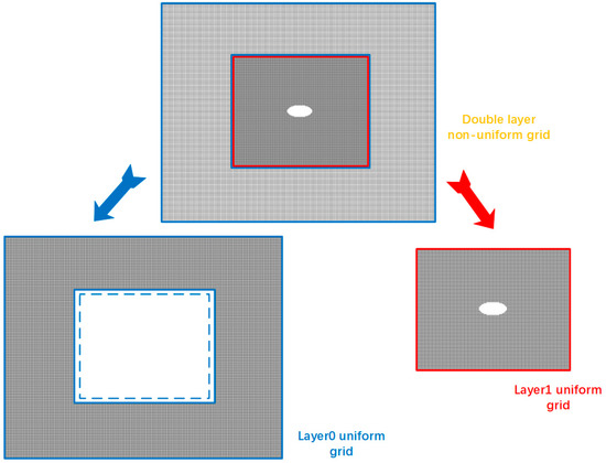
Figure 22.
The two-layer non-uniform grid structure is decomposed into Layer0 uniform grid computational domain (the original outer coarse grid) and Layer1 uniform grid computational domain (the original inner fine grid). The Layer0 uniform grid computational domain also contains the white box area outside the blue dashed line (coarse and fine grid value exchange buffer area).

Table 3.
The first three columns of the table present detailed results on the MPI-dependent performance of the computational domains of the three grid structures, with reference throughput and nesting efficiency\eta calculated from these data, and the results were used to evaluate parallel algorithms.
As can be seen from the tabular data, there was almost no loss in throughput of the multilayer grid in the runtime compared to the reference throughput under the serial condition. This was due to the fact that the computational interpolation step of the multi-layer grid LBM took minimal computational time relative to the uniform grid LBM. The nesting efficiency in the single-threaded mode could reach 96.39%. The efficiency improvement in this mode relied on the interpolation calculation method and buffer arrangement. As the number of threads expanded in the parallel domain, the throughput of uniform grid simulation and multi-layer grid simulation gradually expanded and maintained a good scalability. The decrease in the nesting efficiency was mainly due to the increase in the buffer communication required for interpolation computation. It affected the parallel efficiency of the numerical experiments as much as the boundary buffer communication between different parallel domains in the same level of grid computing domain. When the number of threads was raised to 16, the nesting efficiency of the parallel computation under the load-balanced one-dimensional grid division algorithm proposed in this paper was still as high as 76.96%, which proves the feasibility of the parallel experimental method in this paper.
To evaluate the weak scalability performance and strong scalability performance of our multilayer grid LBM parallel algorithm for fluid computation, benchmark experiments for elliptical cylindrical and circular spherical bypassing in the previous section were used. The grid structure used in the experimental design was also mentioned in the simulation experiments, where a total of 334,445 grids at each level were used for calculations in the 2D simulation problem, and a total of 6,913,848 grids at each level were used for calculations in the 3D simulation problem. Whenever the experiment set the first level of grid resolution to the second level of grid resolution, the automatic mesh generation code updated the current multilayer grid to a more sophisticated grid level. Excluding the MPI communication buffers between grids of the same level and the data transfer buffers in the coarse–fine grid junction region, the overall amount of grids used for collision and migration calculations was correspondingly increased by a factor of four for the 2D problem (eight for the 3D problem). It was discovered that the grid structure of the experimental design was related to the computational load of each level of the grid. It is also important to note that the fine-grid computational domain required an exponentially growing number of iterations in order to unify the time step for one computational iteration of the outermost grid. Each level of the grid’s computational burden was impacted by all of these factors.
In order to test the weak scalability performance, the object of the evaluation experiment was chosen as 2D elliptical cylinder flow experiments, which generated 500,156 number of Cartesian grids. The 2D Cartesian grid refinement was refined to four new fine grids as the number of processing cores rose. With each update, the overall grid quantity was increased by four times. As shown in Table 4, the computation times of the benchmark tests for the three grid resolution levels are given. The weak scalability remained as high as 88.90% for a 16-times increase in the grid quantity. It can be concluded and predicted that the proposed multilayer grid parallel algorithm can have a considerably higher weak scalability performance on more processes.

Table 4.
The weak scalability results of 2D elliptical cylinder flow.
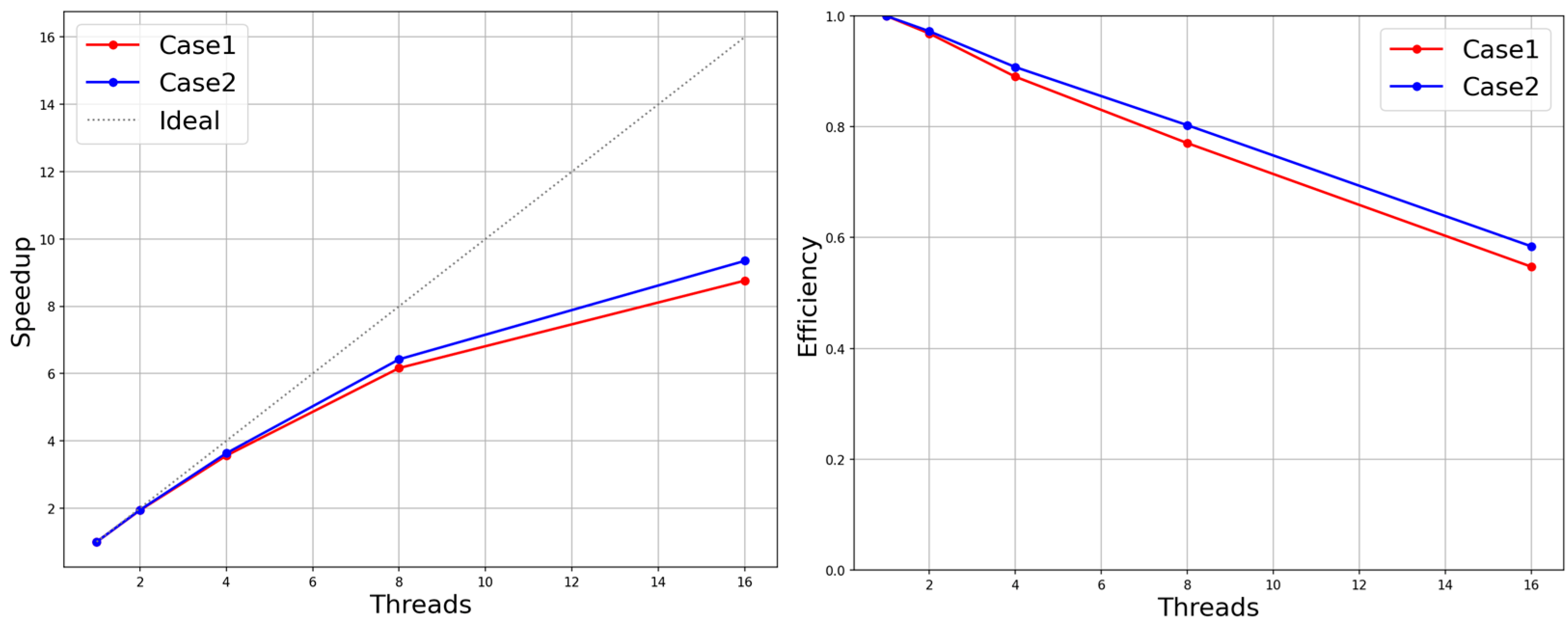
To test the strong scalability performance, a three-dimensional sphere-bypassing benchmark test with multiple levels of cubic Cartesian grids was used. Since the static fine grid structure in this paper was mostly determined by user-defined behavior, the hierarchy and geometry of the computational domain grid varied widely. This paper intended to explore the impact of grid structure variation on the parallel performance of the multi-layer grid LBM in the process of the strong scalability performance evaluation test. Here, the validation experiment’s 3D sphere-bypassing benchmark test grid structure was adopted, which consisted of two levels of the sphere boundary refinement grid area and three layers of the enclosing box refinement grid area (case1). Meanwhile, in the evaluation phase, the experimental design removed the outermost coarse grid of the computational domain space for an experimental object (case2). The size of the global computational space was thus reduced, though with the loss of approximately 122,880 coarse meshes. The experiments were still set with the same boundary conditions as the original ones to simulate the experiments, because the evaluation of the parallel performance could temporarily ignore the results of the simulated experiments. The computational resources for the serial environment as well as the parallel environment with 2,4,8 and 16 threads were given in this experiment. Figure 23 shows the speed-up ratio and efficiency of the parallel algorithm proposed in the article in the two computational domain structures. In both experimental groups, excluding the outermost coarse mesh enclosing the box in one group, the other evolutionary iterative steps were basically the same in the remaining mesh structure. It can be understood that the parallel evolution process of case1 only had more collision, migration and interpolation of the outermost grid and the necessary communication in parallel than that of case2. It can be observed from Figure 23 that the outermost grid increment of 122,880 slightly improved the parallel efficiency. This led to the tentative conclusion that as the grid quantity and grid hierarchy complexity rose, so did the scalability performance of the parallel algorithm based on the load balancing proposed in this research. In the actual simulation scenario, the user needs to select a certain area within the fixed computational domain for local mesh refinement (refinements can be selected in multiple scopes, with each refinement generating a new refinement grid level) instead of adding or subtracting the outermost grid region from the existing grid multilayer structure. Following this process, the overall mesh size and mesh structure complexity increased simultaneously for each selected range of local mesh refinement methods within a certain range. Then, whether the parallel efficiency will increase accordingly. The conclusion will be given in the later experiments.
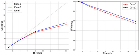
Figure 23.
Speed-up and efficiency in the two different groups of grid structures.
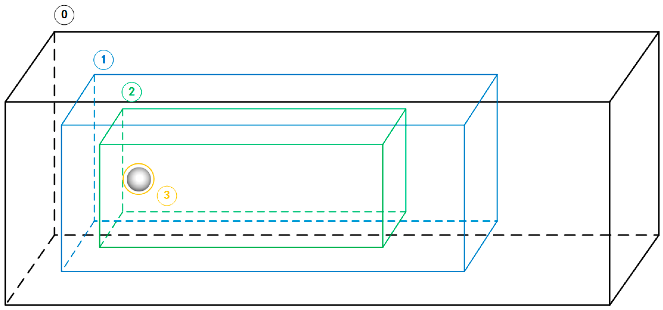
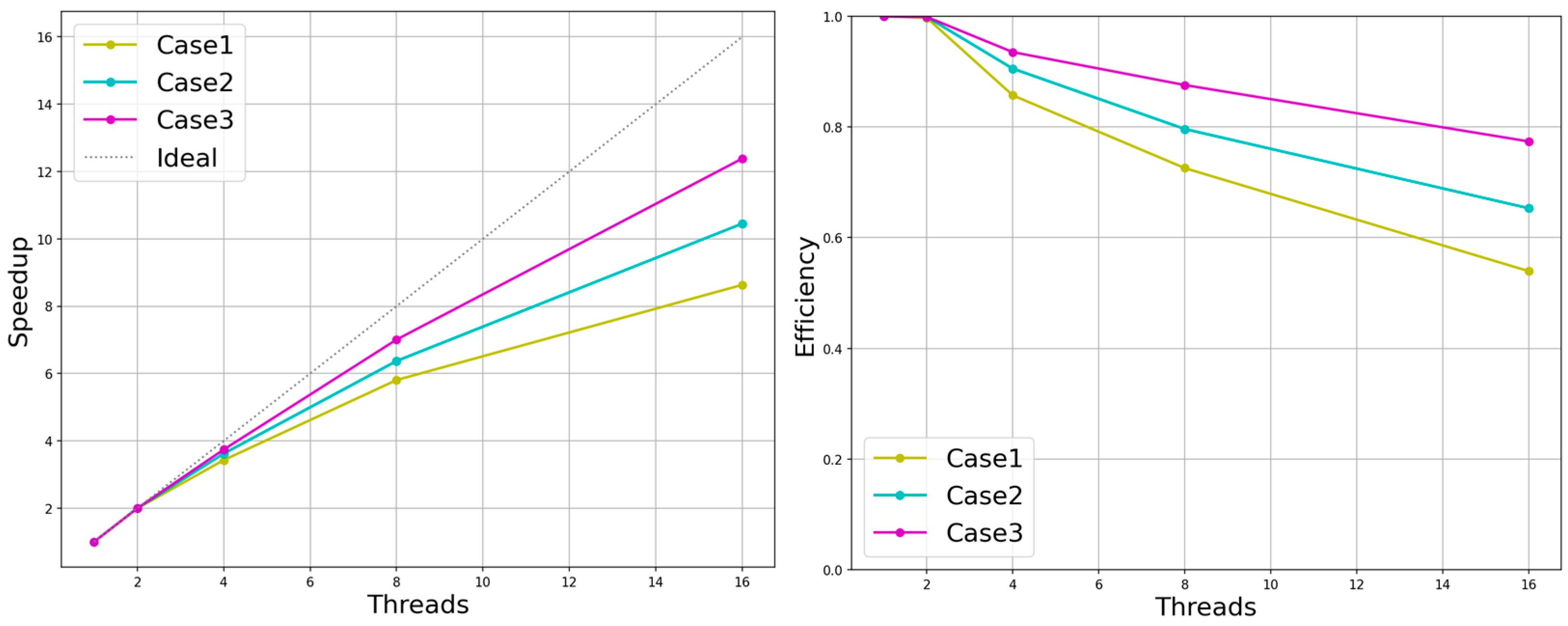
The multi-layer grid LBM parallel algorithm must consider the impact of the complex multi-layer grid structure on parallel efficiency. The experimental object selected in this paper was the sphere-bypassing test in the validation experiment. The experiment was based on an outermost 3D mesh. According to our automatic mesh-generation code, either manually setting the local mesh refinement within the multi-layer enclosing box or setting the simulation environment to push several layers of mesh outside the boundary grid around the solid for local mesh refinement was allowed. The experiments were set up for the numerical simulation of three groups of static fine mesh structures, which were multi-level enclosing box structures (one layer, two layers and three layers) nested in four groups of the extrapolated six-layer fitting body refined mesh. They corresponded to case1, case2 and case3 in the experiment, respectively, as shown in Figure 24. In the performance evaluation in this paper, the speed-up ratio and parallel efficiency of the three sets of experiments in different multi-threaded environments were recorded, as shown in Figure 25. In summary, it can be concluded that the parallel algorithm given in this paper was influenced by the overall mesh volume and the complexity of the mesh structure.
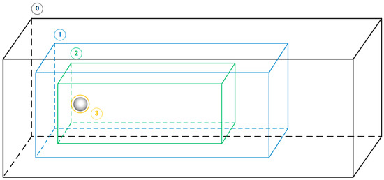
Figure 24.
The local refinement structure of multiple enclosing boxes and fitting body meshes was set in the rectangular computational domain. The structure diagrams 0, 1 and 2 indicate the geometry of the enclosing box, respectively. Point 3 indicates the local mesh refinement of the four round boundaries extrapolating the six-layer mesh. The mesh resolution of all four regions depended on the mesh resolution of its upper layer. The grid size of the enclosing box 0 was fixed as 80 × 48 × 48. The region of (0) + (3) denotes the schematic of case1, (0) + (1) + (3) denotes the schematic of case2 and (0) + (1) + (2) + (3) denotes the schematic of case3.
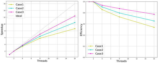
Figure 25.
Speed-up and efficiency in the three different groups of grid structures.
6. Conclusions
The main features of the LBM are a clear physical background, a simple algorithm and good parallelism, so it is well suited for parallel computation on large-scale clusters. However, it is difficult to accurately simulate complex flows using a standard LBM with a uniform grid as the computational grid. The focus of our research direction was the combination of multilayer grid technology and parallel computing technology. In this article, the program framework and implementation details of the multi-layer grid LBM parallel algorithm was introduced, including the boundary-processing conditions of the flow field calculation domain, the refinement scheme of the lattice model and the algorithm details of the parallel program framework. For the simulation experiments, the boundary processing format of the horizontal wall boundary, the entrance boundary, the exit boundary and the solid surface boundary in the simulation scene were given. In order to facilitate the programming operation, the local mesh refinement scheme adopted the center point format and referred to the DC method to realize the evolution process on the coarse and refined meshes. The focus of this paper was on load-balanced meshing techniques under a multi-layer grid LBM. The main idea was to divide the computational domain of a multi-layer refinement grid in each refinement level in a sequential and uniform one-dimensional manner by the number of grids. Finally, the computational domains of each process were combined according to the original arrangement of the multi-layer grid. Based on this grid-partitioning strategy and the MPI parallel programming model, a case of an elliptic cylindrical bypass on a homogeneous platform was tested. The final numerical experiments verified that the parallel algorithm had good scalability and parallel efficiency. The weak scalability performance under 2D simulations was maintained at around 90%, while the parallel efficiency aspect of the strong scalability performance under 3D simulations also performed well. A specific multi-layer grid structure could also have 77.4% results in a 16-threaded environment.
Author Contributions
Conceptualization, Z.L. and J.R.; methodology, Z.L. and J.R.; software, Z.L. and J.R.; validation, Z.L., J.R. and L.Z.; investigation, L.Z. and W.S.; resources, Z.L., L.Z. and W.S.; data curation, W.S.; writing—original draft preparation, Z.L., W.S. and J.R.; writing—review and editing, W.S., W.G. and J.X.; supervision, W.S., W.G. and J.X.; project administration, L.Z. and W.S.; funding acquisition, W.S. All authors have read and agreed to the published version of the manuscript.
Funding
This research was funded by National Key Research and Development Program of China (Grant No.2021YFC3101601); National Natural Science Foundation of China (Grant No. 61972240) and the Program for the Capacity Development of Shanghai Local Colleges (Grant No. 20050501900).
Institutional Review Board Statement
Not applicable.
Informed Consent Statement
Not applicable.
Data Availability Statement
The simulation data and code supporting the conclusions of this manuscript will be made available by the authors, without undue reservation, to any qualified researcher.
Acknowledgments
The authors would like to express their gratitude for the support of Fishery Engineering and Equipment Innovation Team of Shanghai High-level Local University.
Conflicts of Interest
The authors declare that there is no conflict of interest regarding the publication of this paper.
References
- Boon, J.P. The lattice boltzmann equation for fluid dynamics and beyond. Eur. J. Mech. B Fluids 2003, 22, 101. [Google Scholar] [CrossRef]
- Yu, D. Viscous Flow Computations with the Lattice-Boltzmann Equation Method. Ph.D. Thesis, University of Florida, Gainesville, FL, USA, 2002; p. 4260. [Google Scholar]
- Chen, S.; Chen, H.; Martnez, D.; Matthaeus, W. Lattice Boltzmann model for simulation of magnetohydrodynamics. Phys. Rev. Lett. 1991, 67, 3776. [Google Scholar] [CrossRef] [PubMed]
- Qian, Y.H.; d’Humières, D.; Lallemand, P. Lattice BGK models for Navier-Stokes equation. Europhys. Lett. 1992, 17, 479. [Google Scholar] [CrossRef]
- d’Humières, D. Generalized lattice-Boltzmann equations, rarefied gas dynamics. Prog. Aeronaut. Astronaut. 1992, 159, 450–458. [Google Scholar]
- Lallemand, P.; Luo, L.S. Theory of the lattice Boltzmann method: Dispersion, dissipation, isotropy, Galilean invariance, and stability. Phys. Rev. E 2000, 61, 6546. [Google Scholar] [CrossRef]
- Agarwal, A.; Gupta, S.; Prakash, A. A comparative study of three-dimensional discrete velocity set in LBM for turbulent flow over bluff body. J. Braz. Soc. Mech. Sci. Eng. 2021, 43, 39. [Google Scholar] [CrossRef]
- Wellein, G.; Zeiser, T.; Hager, G.; Donath, S. On the single processor performance of simple lattice Boltzmann kernels. Comput. Fluids 2006, 35, 910–919. [Google Scholar] [CrossRef]
- Körner, C.; Pohl, T.; Rüde, U.; Thürey, N.; Zeiser, T. Parallel lattice Boltzmann methods for CFD applications. In Numerical Solution of Partial Differential Equations on Parallel Computers; Springer: Berlin/Heidelberg, Germany, 2006; pp. 439–466. [Google Scholar]
- Guo, W.; Jin, C.; Li, J. High performance lattice Boltzmann algorithms for fluid flows. In Proceedings of the 2008 International Symposium on Information Science and Engineering, Shanghai, China, 20–22 December 2008; Institute of Electrical and Electronics Engineers: Piscataway, NJ, USA, 2008; Volume 1, pp. 33–37. [Google Scholar]
- Liu, G.; Zhang, J.; Zhang, Q. A high-performance three-dimensional lattice Boltzmann solver for water waves with free surface capturing. Coast. Eng. 2021, 165, 103865. [Google Scholar] [CrossRef]
- Williams, S.; Carter, J.; Oliker, L.; Shalf, J.; Yelick, K. Lattice Boltzmann simulation optimization on leading multicore platforms. In Proceedings of the 2008 IEEE International Symposium on Parallel and Distributed Processing, Miami, FL, USA, 14–18 April 2008; Institute of Electrical and Electronics Engineers: Piscataway, NJ, USA, 2008; pp. 1–14. [Google Scholar]
- Lacoursière, C. A parallel block iterative method for interactive contacting rigid multibody simulations on multicore PCs. In International Workshop on Applied Parallel Computing; Springer: Berlin/Heidelberg, Germany, 2006; pp. 956–965. [Google Scholar]
- Donath, S.; Iglberger, K.; Wellein, G.; Zeiser, T.; Nitsure, A.; Rude, U. Performance comparison of different parallel lattice Boltzmann implementations on multi-core multi-socket systems. Int. J. Comput. Sci. Eng. 2008, 4, 3–11. [Google Scholar] [CrossRef]
- Ma, H.; Zhao, Y. An approach to distribute the marker points on non-spherical particle/boundary surface within the IBM-LBM framework. Eng. Anal. Bound. Elem. 2019, 108, 254–266. [Google Scholar] [CrossRef]
- Asmuth, H.; Olivares-Espinosa, H.; Nilsson, K.; Ivanell, S. The actuator line model in lattice Boltzmann frameworks: Numerical sensitivity and computational performance. J. Phys. Conf. Ser. 2019, 1256, 012022. [Google Scholar] [CrossRef]
- Ye, H.; Shen, Z.; Xian, W.; Zhang, T.; Tang, S.; Li, Y. OpenFSI: A highly efficient and portable fluid–structure simulation package based on immersed-boundary method. Comput. Phys. Commun. 2020, 256, 107463. [Google Scholar] [CrossRef]
- Filippova, O.; Hänel, D. Grid refinement for lattice-BGK models. J. Comput. Phys. 1998, 147, 219–228. [Google Scholar] [CrossRef]
- Maeyama, H.; Imamura, T.; Osaka, J.; Kurimoto, N. Unsteady aerodynamic simulations by the lattice Boltzmann method with near-wall modeling on hierarchical Cartesian grids. Comput. Fluids 2022, 233, 105249. [Google Scholar] [CrossRef]
- Lin, C.L.; Lai, Y.G. Lattice Boltzmann method on composite grids. Phys. Rev. E 2000, 62, 2219. [Google Scholar] [CrossRef] [PubMed]
- Dupuis, A.; Chopard, B. Theory and applications of an alternative lattice Boltzmann grid refinement algorithm. Phys. Rev. E 2003, 67, 066707. [Google Scholar] [CrossRef]
- Ezzatneshan, E. Study of unsteady separated fluid flows using a multi-block lattice Boltzmann method. Aircr. Eng. Aerosp. Technol. 2020, 93, 139–149. [Google Scholar] [CrossRef]
- Hsu, F.S.; Chang, K.C.; Smith, M. Multi-block adaptive mesh refinement (AMR) for a lattice Boltzmann solver using GPUs. Comput. Fluids 2018, 175, 48–52. [Google Scholar] [CrossRef]
- Jiao, H.; Wu, G.X. Effect of Reynolds number on amplitude branches of vortex-induced vibration of a cylinder. J. Fluids Struct. 2021, 105, 103323. [Google Scholar] [CrossRef]
- Guzik, S.M.; Weisgraber, T.H.; Colella, P.; Alder, B.J. Interpolation methods and the accuracy of lattice-Boltzmann mesh refinement. J. Comput. Phys. 2014, 259, 461–487. [Google Scholar] [CrossRef]
- Hasert, M.; Masilamani, K.; Zimny, S.; Klimach, H.; Qi, J.; Bernsdorf, J.; Roller, S. Complex fluid simulations with the parallel tree-based lattice Boltzmann solver Musubi. J. Comput. Sci. 2014, 5, 784–794. [Google Scholar] [CrossRef]
- Neumann, P.; Neckel, T. A dynamic mesh refinement technique for Lattice Boltzmann simulations on octree-like grids. Comput. Mech. 2013, 51, 237–253. [Google Scholar] [CrossRef]
- Schornbaum, F.; Rude, U. Massively parallel algorithms for the lattice Boltzmann method on nonuniform grids. SIAM J. Sci. Comput. 2016, 38, C96–C126. [Google Scholar] [CrossRef]
- Kotsalos, C.; Latt, J.; Chopard, B. Palabos-npFEM: Software for the simulation of cellular blood flow (digital blood). arXiv 2020, arXiv:2011.04332. [Google Scholar]
- Krause, M.J.; Kummerländer, A.; Avis, S.J.; Kusumaatmaja, H.; Dapelo, D.; Klemens, F.; Gaedtke, M.; Hafen, N.; Mink, A.; Trunk, R.; et al. OpenLB—Open source lattice Boltzmann code. Comput. Math. Appl. 2021, 81, 258–288. [Google Scholar] [CrossRef]
- Schmieschek, S.; Shamardin, L.; Frijters, S.; Krüger, T.; Schiller, U.D.; Harting, J.; Coveney, P.V. LB3D: A parallel implementation of the Lattice-Boltzmann method for simulation of interacting amphiphilic fluids. Comput. Phys. Commun. 2017, 217, 149–161. [Google Scholar] [CrossRef]
- Patronis, A.; Richardson, R.A.; Schmieschek, S.; Wylie, B.J.; Nash, R.W.; Coveney, P.V. Modeling patient-specific magnetic drug targeting within the intracranial vasculature. Front. Physiol. 2018, 9, 331. [Google Scholar] [CrossRef]
- Vardhan, M.; Gounley, J.; Hegele, L.; Draeger, E.W.; Randles, A. Moment representation in the lattice Boltzmann method on massively parallel hardware. In Proceedings of the International Conference for High Performance Computing, Networking, Storage and Analysis, Denver, CO, USA, 17–19 November 2019; pp. 1–21. [Google Scholar]
- Jäger, S.; Ludwig, A. Efficient model for the prediction of dendritic grain growth using the lattice Boltzmann method coupled with a cellular automaton algorithm. IOP Conf. Ser. Mater. Sci. Eng. 2019, 529, 012028. [Google Scholar] [CrossRef]
- Sharma, K.V.; Straka, R.; Tavares, F.W. Current status of Lattice Boltzmann Methods applied to aerodynamic, aeroacoustic, and thermal flows. Prog. Aerosp. Sci. 2020, 115, 100616. [Google Scholar] [CrossRef]
- Sridhar, V.; Ramesh, K.; Gnaneswara Reddy, M.; Azese, M.N.; Abdelsalam, S.I. On the entropy optimization of hemodynamic peristaltic pumping of a nanofluid with geometry effects. Waves Random Complex Media 2022, 1–21. [Google Scholar] [CrossRef]
- Alsharif, A.M.; Abdellateef, A.I.; Elmaboud, Y.A.; Abdelsalam, S.I. Performance enhancement of a DC-operated micropump with electroosmosis in a hybrid nanofluid: Fractional Cattaneo heat flux problem. Appl. Math. Mech. 2022, 43, 931–944. [Google Scholar] [CrossRef]
- Thumma, T.; Mishra, S.R.; Abbas, M.A.; Bhatti, M.M.; Abdelsalam, S.I. Three-dimensional nanofluid stirring with non-uniform heat source/sink through an elongated sheet. Appl. Math. Comput. 2022, 421, 126927. [Google Scholar] [CrossRef]
- Liu, Z.; Chen, R.; Xu, L. Parallel unstructured finite volume lattice Boltzmann method for high-speed viscid compressible flows. Int. J. Mod. Phys. C 2022, 33, 2250066. [Google Scholar] [CrossRef]
- Yu, D.; Mei, R.; Luo, L.S.; Shyy, W. Viscous flow computations with the method of lattice Boltzmann equation. Prog. Aerosp. Sci. 2003, 39, 329–367. [Google Scholar] [CrossRef]
- Ma, Y.; Wang, Y.; Xie, M. Multiblock adaptive mesh refinement for the SN transport equation based on lattice Boltzmann method. Nucl. Sci. Eng. 2019, 193, 1219–1237. [Google Scholar] [CrossRef]
- Perumal, D.A.; Dass, A.K. Multiplicity of steady solutions in two-dimensional lid-driven cavity flows by lattice Boltzmann method. Comput. Math. Appl. 2011, 61, 3711–3721. [Google Scholar] [CrossRef]
- Guo, K.; Cui, X.; Liu, M. A coupled lattice Boltzmann-Volume penalization for flows past fixed solid obstacles with local mesh refinement. Math. Probl. Eng. 2018, 2018, 6732082. [Google Scholar] [CrossRef]
- McNamara, G.R.; Zanetti, G. Use of the Boltzmann equation to simulate lattice-gas automata. Phys. Rev. Lett. 1988, 61, 2332. [Google Scholar] [CrossRef]
- Guo, Z.; Zheng, C.; Shi, B. An extrapolation method for boundary conditions in lattice Boltzmann method. Phys. Fluids 2002, 14, 2007–2010. [Google Scholar] [CrossRef]
- Bouzidi, M.H.; Firdaouss, M.; Lallemand, P. Momentum transfer of a Boltzmann-lattice fluid with boundaries. Phys. Fluids 2001, 13, 3452–3459. [Google Scholar] [CrossRef]
- Lallemand, P.; Luo, L.S. Lattice Boltzmann method for moving boundaries. J. Comput. Phys. 2003, 184, 406–421. [Google Scholar] [CrossRef]
- Yu, D.; Mei, R.; Shyy, W. A unified boundary treatment in lattice boltzmann method. In Proceedings of the 41st Aerospace Sciences Meeting and Exhibit, Reno, NV, USA, 6–9 January 2003. [Google Scholar]
- Fakhari, A.; Lee, T. Numerics of the lattice Boltzmann method on nonuniform grids: Standard LBM and finite-difference LBM. Comput. Fluids 2015, 107, 205–213. [Google Scholar] [CrossRef]
- Zhang, Y.; Xie, J.; Li, X.; Ma, Z.; Zou, J.; Zheng, Y. A multi-block adaptive solving technique based on lattice Boltzmann method. Mod. Phys. Lett. B 2018, 32, 1840052. [Google Scholar] [CrossRef]
- Schönherr, M.; Kucher, K.; Geier, M.; Stiebler, M.; Freudiger, S.; Krafczyk, M. Multi-thread implementations of the lattice Boltzmann method on non-uniform grids for CPUs and GPUs. Comput. Math. Appl. 2011, 61, 3730–3743. [Google Scholar] [CrossRef]
- Perumal, D.A.; Kumar, G.V.; Dass, A.K. Lattice Boltzmann simulation of viscous flow past elliptical cylinder. CFD Lett. 2012, 4, 127–139. [Google Scholar]
- Gilmanov, A.; Sotiropoulos, F.; Balaras, E. A general reconstruction algorithm for simulating flows with complex 3D immersed boundaries on Cartesian grids. J. Comput. Phys. 2003, 191, 660–669. [Google Scholar] [CrossRef]
- Xu, L.; Li, J.; Chen, R. A scalable parallel unstructured finite volume lattice Boltzmann method for three-dimensional incompressible flow simulations. Int. J. Numer. Methods Fluids 2021, 93, 2744–2762. [Google Scholar] [CrossRef]
Publisher’s Note: MDPI stays neutral with regard to jurisdictional claims in published maps and institutional affiliations. |
© 2022 by the authors. Licensee MDPI, Basel, Switzerland. This article is an open access article distributed under the terms and conditions of the Creative Commons Attribution (CC BY) license (https://creativecommons.org/licenses/by/4.0/).

