1. Introduction
Induction motors (IMs) are used in an enormous variety of systems and applications, and this number is growing as new technologies are developed. The common way to know an induction motor’s speed is the use of a speed sensor or tachometer to measure it. The use of those external devices can increase production or maintenance costs. In some situations, knowledge of induction motor operating speed is crucial or even vital. For example, the speed data can be an identification tool for the motor unbalance if the instantaneous motor speed on the mining or artificial oil lift mechanical pumping equipment is known [
1]. In addition, the real-time speed is useful for the motor control system. It can also be used to calculate the motor’s online output power for in situ efficiency estimation. The real-time speed data can be an information system for rotor eccentricity, bearing faults, etc. The above statements show the importance of real-time motor speed estimation, among others. The difficulty of motor speed estimation is extracting the existing harmonics in the current for speed estimation.
Among other techniques, the utilization of spectral harmonics associated with the number of rotor slots present in the stator current of the induction motor has been examined and found to be a successful technique for estimating the motor speed of the shaft [
2]. It is highlighted in [
3] that this approach can be used if the frequency and load are not varying. The precision of this method depends on how precisely it is feasible to carry out the spectral harmonics related to the rotor slots detection. Fast Fourier transform (FFT), discrete Fourier transform (DFT), and digital signal processing (DSP) are the dominant digital signal processing method for identifying these spectral components. Furthermore, due to some restrictions on accurately identifying spectral components, particular consideration must be given to their use.
Because of the current’s non-stationarity, the entire spectrum will undoubtedly see changes through time when the motor’s rotational speed is not constant. In this case, recovering the time-frequency information is more challenging than if it was in the stationary condition. To deal with this, the Chirp-Z transform (CZT) has been presented in [
4] to find out the harmonics of the rotor slots. Additionally, it has demonstrated that when the motor is running in non-stationary mode, it is feasible to estimate the motor speed data and that the results from CZT are quite accurate to the ones from FFT. The Chirp-Z transform (CZT) technique is frequently utilized in different disciplines such as radar range, power prediction, and others because it is more versatile than the FFT in determining the frequency spectrum. In addition, in [
5], the adaptive notch filter algorithm-based speed detecting technique was used to estimate the motor speed, where the block diagram of the proposed filter, the controlling equations, and all the mathematical concepts are presented. The slot number is not necessary in [
5] because this method does not employ slots or slot harmonics. The μ parameters in the block diagram shall be adjusted. A data collection measurement device captured the one-line current signal, which was then sent through a notch filter to identify the central element or component. The FFT and noise filtering were employed to extract two frequencies as the frequency estimation range. Then the average value of the two identified frequencies was calculated and stated to be the estimated speed. The use of notch filter algorithms, noise filtering, FFT, and averaging can simultaneously increase the computational complexity and lead to an inaccurate speed estimation. Long sample times are necessary, especially at low speeds, for the effective extraction of saliency harmonics from the stator current by digital signal processing (DSP) techniques. In [
6], the main benefit of DSP over analog methods for frequency measurement is explained by observation. In analog filtering, frequency resolution decreases with
f1, while frequency resolution does not change for digital filtering; hence, the sampling time rises inversely with
f1. Thus, digital filtering can generate reliable speed detection at any nonzero speed, whereas at slow speeds, analog filtering is ineffective for saliency harmonic monitoring. Digital systems have good resolution, but as a trade-off, the necessary sampling time typically rises inversely with
f1 for a given frequency resolution. According to the uncertainty principle, an FFT’s frequency resolution is fixed as the inverse of the block’s total sampling time. In practice, the uncertainty principle drastically limits the FFT spectrum resolution when only eight data cycles are sampled. The scaled periodic discrete Fourier transform (SPDFT) was adopted in [
7] to determine unambiguous Doppler frequency and the target’s high speed after using scaled non-uniform fast Fourier transform (SNuFFT) and others, which can increase the time and computational burden. Only when there is a significant amount of sampled data is an FFT-based approach best suited for slot harmonic identification.
In the literature, many CZT-based methods have been proposed to improve its capabilities for the signal process. Multiple-receiver synthetic aperture sonar CZT (SASCZT) was proposed for image processing [
8]. Modified iterative Chirp-Z transform (MICZT) was proposed in [
9]; however, the authors did not account for existing interferences. The sparse inverse Chirp-Z Transform approach was used to detect cable faults in [
10]. In [
11], the advantages of CZT, singular value decomposition (SVD), and discrete wavelet transform (DWT) were combined to make an audio watermarking algorithm. In [
12], CZT was repeatedly used for the Doppler ambiguity search, increasing computational complexity. As can be observed in the above passage, most recent papers for signal process or detection used a CZT-based algorithm to improve the CZT process or detection capabilities. Authors have agreed that combining CZT and other signal processing methods can effectively improve its signal or frequency detection abilities.
In the same way or for the same reason, a CZT-based algorithm is proposed in this paper to extract induction motor rotor slot harmonics frequencies for the motor’s speed estimation to obtain an efficient signal processing tool. However, it does not consider the scenario where the motor is acting as a generator because the searching frequency band in the proposed algorithm does not stretch above the frequency in which the negative slip can occur. The proposed method uses a rotor slot number, and it can be given by manufacturers or accurately identified. A preliminary investigation of speed estimation in strongly non-stationary motor operating conditions was highlighted in [
13], demonstrating how the window length can act as a low-pass filter. The algorithm was updated in this paper, and we used an improved Chirp-Z transform called “Zoom Improved Short-Time Chirp-Z Transform” (ZISTCZT) to search the frequency of the supply as well as the frequency of the rotor slot harmonic. This approach helps improve the determination accuracy of induction motor speed.
This paper’s contribution is the following: First, zoom improved short-time Chirp-Z transform is utilized to determine the frequency of the supply and the rotor slot harmonic frequency in order to increase or enhance the estimation precision without adding to the computation complexity. Second, a technique is described that can be used to determine whether or not a motor can produce primary slot harmonics (PSH). To do so, some equations have been analytically developed that deal with the frequency of rotor slot harmonics and a formula that can evaluate whether a motor can produce principal slot harmonics (PSH). Furthermore, simulations have been conducted with Matlab software to analyze the effectiveness of the proposed technique for signal processing. The proposed technique works with a vital parameter called window length. This parameter is very important in this method. An optimum method to determine the perfect observation window length is analyzed to make small errors when estimating the induction motor speed. Finally, experiments were conducted on 5.5 kW and 22 kW induction motors to show the effectiveness and validate the proposed technique. The results have shown good accuracy.
2. Analysis of Statics Eccentricity of Healthy Induction Motors
It is crucial to identify rotor slots and other eccentricity-related harmonics in a three-phase motor’s line current both from the point of view of sensorless speed estimation and eccentricity-associated fault detection. According to recent studies, the machine’s pole pairs and rotor slot counts are the principal contributors to the presence of these harmonics. While a three-phase induction motor’s fundamental pole pairs typically range from one to four (higher pole pairs are often avoided due to increased magnetizing current), the number of rotor slots can vary significantly. An induction motor’s air-gap field, when supplied with a sinusoidal voltage supply waveform, contains various harmonics caused by winding distribution, slotting saturation, air-gap eccentricity, etc. The analysis that follows presumes that these air-gap flux harmonics result from the interaction of air-gap permeance and harmonic magnetomotive force (MMF) waves. In this work, only harmonics caused by slotting are taken into account. The number of rotor slots Z determines the spatial distribution of the air-gap permeance waves that are produced by the slots. This interacts with the fundamental (magnetizing) component of the air-gap MMF produced by the fundamental MMFs of the rotor and stator. Two harmonic components of the air-gap flux density are produced by the modulation process, and their frequencies are distanced from the rotor slot passing frequency by the fundamental frequency of the stator current. Usually, except in machines with closed rotor slots, the magnitude of these flux harmonics does not significantly change with load. Similar air-gap flux harmonics result from the interaction of slip frequency and rotor currents with the regular portion of the air-gap permeance, which interacts with the MMF harmonics in the rotor slot. The MMF harmonics continually decrease in magnitude with decreasing load since they are directly associated with rotor current in this scenario. This ripple, which is spatially and temporally variable, mathematically corresponds to two waves going in opposite directions that produce matching current harmonics in the stator windings. The induced current in one-phase winding can be formulated as:
where
An and
ψn are, respectively, the amplitude and phase of the nth harmonic component. It is possible to retrieve the currents generated in the other two phases of the three-phase system by introducing 2
π/3 and 4
π/3 phase shifts, respectively, into the argument of (1).
For motor speed estimation or diagnostics, a sufficient understanding of the harmonic components of the stator current is essential. Machine theory claims that if a symmetrical three-phase stator winding of a motor, precisely a SCIM (squirrel cage induction motor), is fed with a symmetrical voltage system, a forward MMF is induced in the air gap. At slip frequency
sf1, this MMF creates a current in a rotor loop. A current with the same magnitude and frequency but phase-shifted by an electrical angle
ae flows in the following rotor loop, which is spatially offset by the mechanic angle
a/
p. The electromagnetic torque can be expressed as in (2).
where [
is] is the vector of the stator line current, with the
ith component for stator harmonic (
hs) component given by:
[
ir] is the vector in the rotor line current, with the kth component for rotor harmonic (h
r) component given by (4),
ae =
p(2
π/nb) is the rotor electrical loop angle, θ is the position of rotor electrical angle, and
Is(r) denotes the maximum current.
θshs (θrhr) is the component of the stator (rotor) angle of the hs (hr) harmonic related to frequency fshs (frhr) by θshs = fshst + θ0hs; θrhr = frhrt + θ0hr; θ0hs and θ0hr are the initial angles. In this study, we are not focusing on the angles.
Considering an induction motor having slots in the stator and rotor, because of the stator slots, the waveform of the air gap magnetomotive force (MMF) is stepped. Although this stepped waveform generates harmonics, the MMF waveform’s fundamental component predominates due to stator winding distribution and skewed rotor slots. Because of this, only the core component of the MMF distribution will be considered in this analysis. Additionally, it is assumed that there are no space undulations on the stator side of the machine and that the only reason the air gap’s permeance varies is because of the openings in the rotor slot. The permeance variation in this circumstance can be formulated as follows:
where
λav is the permeance average magnitude;
λvar is the permeance fluctuation magnitude;
Z is the slot number;
p is the pole-pair number;
ωr is the rotating speed.
The majority of sensorless adjustable speed induction motor drive schemes and the diagnosis of eccentricity-related issues obviously require the existence of rotor slot harmonics (also known as the principal slot harmonics PSH) and other eccentricity-related harmonics [
14]. Equation (6) provides a generalized expression for the PSH and the static and dynamic eccentricity-related frequencies in a three-phase motor line current.
where
fsh and
f1 are, respectively, the current harmonic frequency and the supply frequency;
λ = 0, 1, 2, 3, …, is a positive integer number; the rotor slots number is
Z;
nd ± 1, …, is the rotor eccentricity order;
s is the slip; the pole pairs number is
p;
, is the air gap magneto-motive force (MMF) harmonic order.
To investigate the speed estimation of induction motors using rotor slot harmonics, it is feasible in (6), as shown in [
15,
16], to take
since the first group of components realizes good amplitude detection,
nd = 0, since in a healthy induction motor, the static eccentricity outweighs the dynamic eccentricity. Then, the slip
s is calculated by (7):
Finally, the rotational speed of an induction motor can be determined by the following expression (8), obtained after replacing the slip equation (7), in the expression
n =
ns (1−
s), where the synchronous speed
ns is given by
ns = 60
f1/
p:
By utilizing digital signal processing techniques, the basic supply frequency (f1) and rotor slot harmonics-related frequency (fsh) are identified, as previously said.
The streamlined rotor slot harmonics-related frequency equation is mathematically expressed using the density of the air gap flux [
17]. Meanwhile, it is noteworthy that the rotor slot number can be obtained from the design datasheet from manufacturers or be identified by the method in [
18]. It is assumed that one winding turn is made with two bars and piece rings. The winding function created with one winding turn in the loop is expressed by (9):
Here, the rotor loop1’s magnetic axis is assumed to reference the frame’s center, where the related rotor angle is
θr. Using the Fourier series, this formulation can be re-expressed as:
Then, the MMF generated by the current flowing in loop1 is:
where
,
s is the motor slip. The total rotor MMF is thus determined by adding the MMF of each loop, as in (12):
After an inspection in (12), it can be seen that this MMF exists if:
(1)
; (2)
; (3)
, where (
). Additionally, it should be mentioned that
is associated with the reaction of the stator armature MMF wave since
is associated with the rotor slot harmonics. Consequently, the rotor currents generated by the
stator flux density special harmonic generates the following MMF:
Using the stator reference transformation as a last step,
, the following expression is obtained:
Assuming that
and
, the rotor slot harmonics are then called “principal slot harmonic” (PSH) (15):
From (15), it is clear that the PSH depends on the pole pair number and rotor slots or bars. Investigating Equation (16), one can predict which induction motor can generate PSHs. The following assertion can be formalized by using expression (16).
where
, and
can only be −1, 0, or 1.
= −1, implying that ideally, only the PSH associated with
= 1 will exist. For
= 1, only the PSH associated with
= −1 will ideally exist, and finally,
= 0 implies that both PSHs will exist when
=
.
Table 1 lists some potential rotor slot
Z values for induction motors with four poles that are ideal for producing PSHs, which might be present in the signal, as shown by the columns of this table. As an example, let us take two pole pair induction motors with 40 rotor slots, only PSH related to
= −1 could be present; for
Z = 32, only the PSH related to
= 1 can exist; if
Z = 24, then the PFHs related to
=
could exist. However, if
Z = 30, the PSHs cannot exist.
3. Zoom Improved Chirp-Z Transform
Zoom improved CZT is inspired by some existing digital signal processing techniques. Generally, the information is extracted using mathematical methods according to the theory of digital signal processing, where a sequence of numbers represents the signals. Many signal processing methods exist, among them, fast Fourier transform (FFT), discrete Fourier transform (DFT), digital signal process (DSP), Z-transform, etc. In this scenario, the Chirp-Z transform (CZT) is found to be one of the most powerful tools. The Chirp-Z transform of a sequence
x(n) is expressed as follows [
19]:
By considering the complex variable
for k = 0, 1, 2, …,
N−1 in (17), we obtain a particular case of the Chirp-Z transform. This transform is equivalent to the discrete Fourier transform (DFT) in this situation.
Now let us consider
, where k = 0, 1, 2, …,
M−1,
M is an integer. The CZT is obtained in this scenario and expressed by (19).
where the complex numbers A and W are given by
and
.
However, for A = 1,
M =
N, and
, this function gives the DFT (18). Taking into account that the CZT technique may be used to accurately assess the Z-transform at M locations around circular contours beginning at any location in the Z-plane,
Figure 1 depicts a typical example of CZT. In
Figure 1, the general form of CZT is represented by the spiral curve presented by “
*”. The curve represented by “
x” is a specific configuration of the CZT put up in the radius of a circle. To have this kind of curve, W
0 should be assigned at 1 (W
0 = 1) to have an arc shape with CZT, and A
0 should be 1 (A
0 = 1), where the arc will be on the unitary circle radius. Applying the DFT’s results to the signal,
x[n] will cover the circle radius, or the CZT can be positioned to only cover a specific area of the circle, as shown in
Figure 1. For example, if a signal is digitalized with 360 sample/s as the sampling frequency, and takes into account that eight samples are required to calculate the DFT, the frequency of resolution will be 45 Hz. However, if CZT is carried out between 10 and 80 Hz, 10 Hz is the resolution frequency. This scenario can be perceived in the curve symbolized by “
x” in
Figure 1. In this figure, the first point corresponds to the 10 Hz signal component. Additionally, the DFT is depicted in this picture as a “diamond” that is evenly separated by 45 Hz and covers the unit circle.
The DFT and CZT are very useful instruments in periodical signal processing. However, if the signal’s spectral components change over time, a special tool is needed in order to handle time-frequency representation. The short-time Fourier transform (STFT) is the most common technique for investigating this type of signal. It is accomplished with the aid of a window function W
in(n), as:
In (20), with x(n) being a time function, XSTFT(t,k) is a variable function that has a time (t) and frequency (k) relationship. Typically, Win(n) might be an even function having positive real values that peak near zero. The window function’s length influences the STFT’s time-frequency resolution and depends on the Heisenberg–Gabor restriction. Blackman, Hanning, Bartlett, Hamming, and Gaussian windows are some examples of the window function. The frequency resolution will suffer if the window is reduced to boost time resolution, and inversely. It is necessary to strike a balance between temporal and frequency localization conservation. To have this compromise, there must be an area generated by the frequency bandwidth β and the time span T has to be larger than: .
The trade-off between time and frequency resolution in STFT is clear to perceive. This confirms once more that the most important aspect of this methodology is the window length selection. Recently, with the development of new technologies, scientists and researchers have been looking for better signal-processing tools. For this reason, researchers are combining existing methods to outperform former ones. We found that it is necessary to investigate another technique that can outperform CZT. Furthermore, we found through the simulation results (Figure 3) that when the resources offered by CZT are used with STFT, this can improve the frequency resolution of the CZT, and the short-time Chirp-Z transform (ISTCZT) is employed to differentiate this process from others. Therefore, ISTCZT is written as:
When we consider
, we obtain the same expression as in (19). Especially in comparison to DFT, CZT can enhance frequency resolution, and
ISTCZT also presents an improved effect compared to STFT. The
ISTCZT resolution is given by:
where
flow is associated with
θ0 and
fhigh with ∅
0. However, because the resolution depends on the
M samples, the frequency resolution will be better if a large
M is used; nevertheless, the computing complexity will rise [
20]. For every step of
ISTCZT, the computational cost is provided by:
Therefore, having a large M is a bad decision. The frequency resolution can be improved by zooming on ISTCZT. This zooming technique signifies to resolve ISTCZT in a frequency span (fbw = fhigh−flow) with a small M. When the desired spectral frequency is identified, ISTCZT is computed once more, but with a condensed frequency range fbw close to the identified spectral component. To differentiate this procedure from others, the term “zoom improved short-time Chip-Z transform” ZISTCZT is employed.
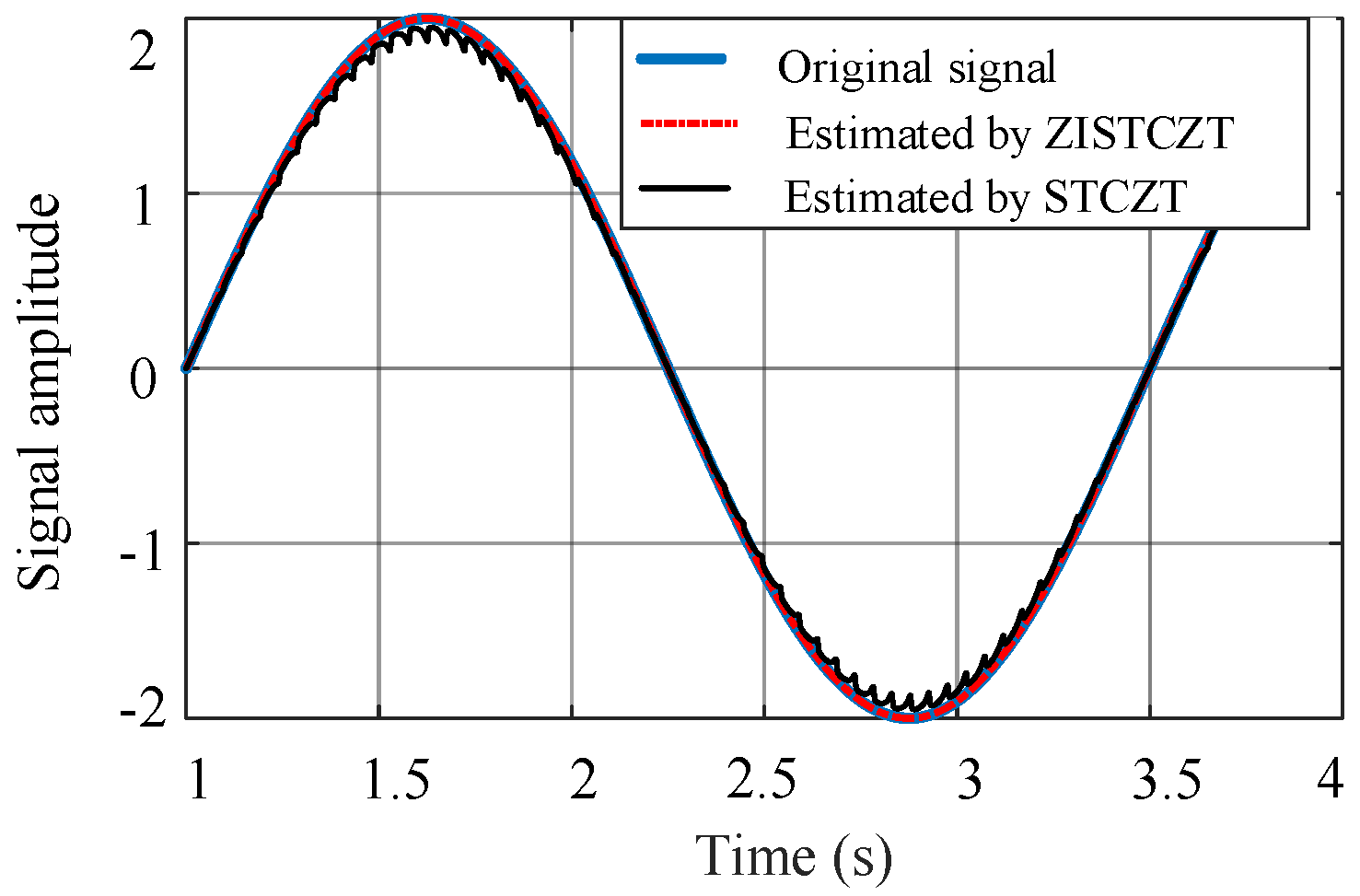
The major distinction between a CZT-based method and the FFT is that the CZT-based technique may be sampled at any place without regard for interval and output at any interval. In order to ease comparability with published studies, a MATLAB program has been used to simulate a frequency-modulated signal to show how much ZISTCZT can enhance frequency resolution. The carrier has a 60 Hz frequency. The frequency of the message signal is 0.4 Hz, and the deviation frequency is 2 Hz. The signal’s sampling rate was 5000 sample/s. The result is depicted in
Figure 2 as the curve in blue color. Previous experiments were conducted to determine the appropriate window function for this simulation. As in [
17], Hamming, Hanning, Kaiser, and Blackman window functions were employed for error investigation. Hanning highlighted the best results. The ISTCZT was performed taking
fhigh = 125 Hz and
flow = 3 Hz with
fbw = 122 Hz. The black curve shows the results of this operation in
Figure 2. Finally, ISTCZT was applied in a range of
fbw = ±5 Hz around the spectral frequency that the first ISTCZT previously identified. The red dashed-dotted curve shows this result in
Figure 2. As can be perceived, the outcome in this scenario closely resembles the original signal. Improvement in frequency resolution can be noticed when ZISTCZT is applied using the ISTCZT.
4. Proposed Technique
It is initially necessary to confirm whether the induction motor can optimally produce principal slot harmonics before estimating an induction motor speed utilizing rotor slot harmonics. This is very helpful for those who might be required to specify the motor that will be monitored utilizing the rotor slots harmonics method.
Table 1, constructed using (16), indicates the motors, which, in perfect circumstances, can produce primary slot harmonics (PSH). This does not imply that finding the rotor slot harmonics is impossible for the motors that are not present in this table, but their quality will not be good enough. An important thing is choosing the appropriate digital signal processing tool and the choice of the window function that the search algorithm will utilize. The precision of the motor speed estimation depends on the required resolution of both supply frequency
f1 and rotor slot harmonics frequency
fsh, as can be perceived in Equation (8). ZISTCZT is performed to find out the supply frequency
f1 and determine the range to be selected to get the rotor slot harmonic frequency
fsh and then determine the speed using (8).
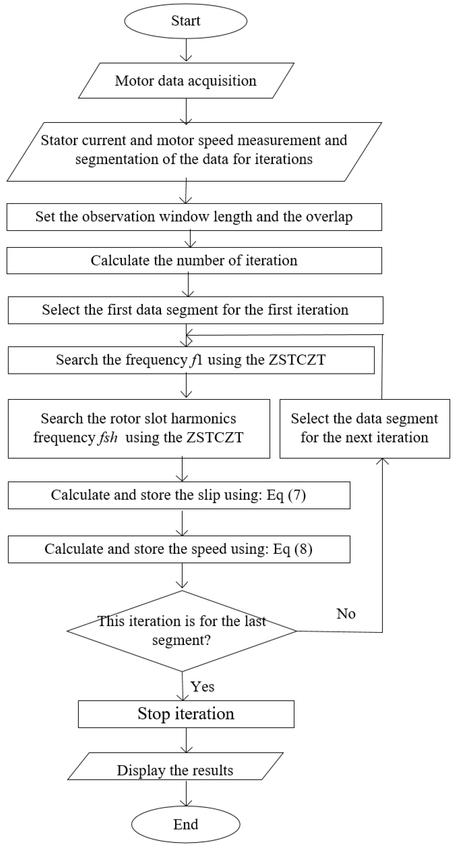
The flowchart of the proposed technique is presented in
Figure 3. In this flowchart, the main steps of the algorithm are emphasized for determining the motor’s rotational speed. Initial data, such as rated slip, pole pair number, and rotor slot number, are required. With the data acquisition system, the current signal in one of the induction motor phases is collected, and the samples are kept for investigation. An observation window length and the overlap are regulated. The ZISTCZT algorithm is then executed to determine the supply frequency
f1. The ZISTCZT is conducted using ISTCZT twice. For the first time, the frequency span extended from
flow = 0 Hz to
fhigh = 100, presuming that the converter’s output frequency could not exceed this range. As for the second time, the span presumed was
fbw = ±5 Hz around the frequency that the first ISTCZT initially discovered. The
fbw = ±5 Hz was used to increase the frequency
f1 resolution. A search range for
fsh can be established using the motor-rated slip. Now, taking the best PSH (δ), which can be determined with expression (16), the rotor slot harmonic
fsh can be found using the ISTCZT tool.
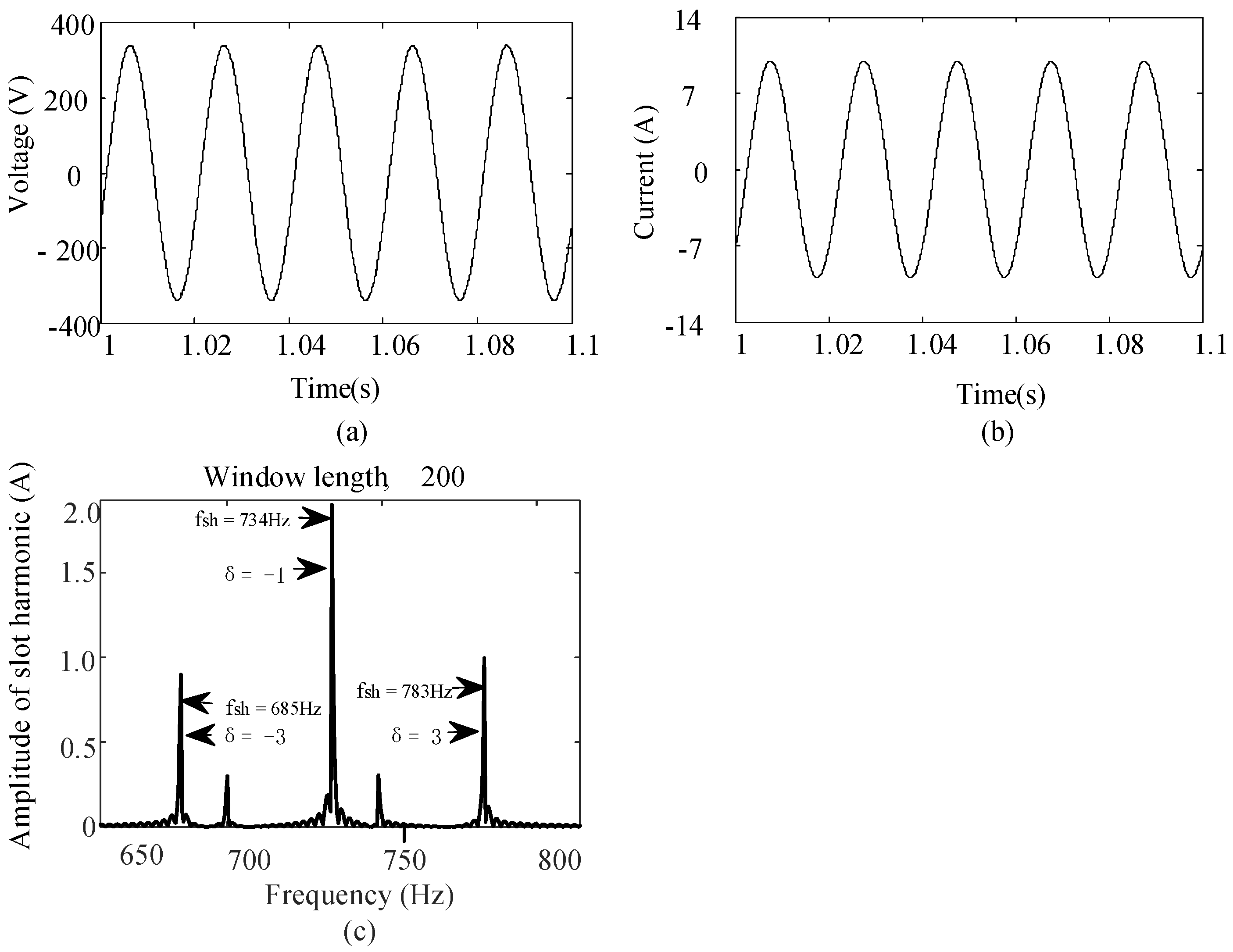
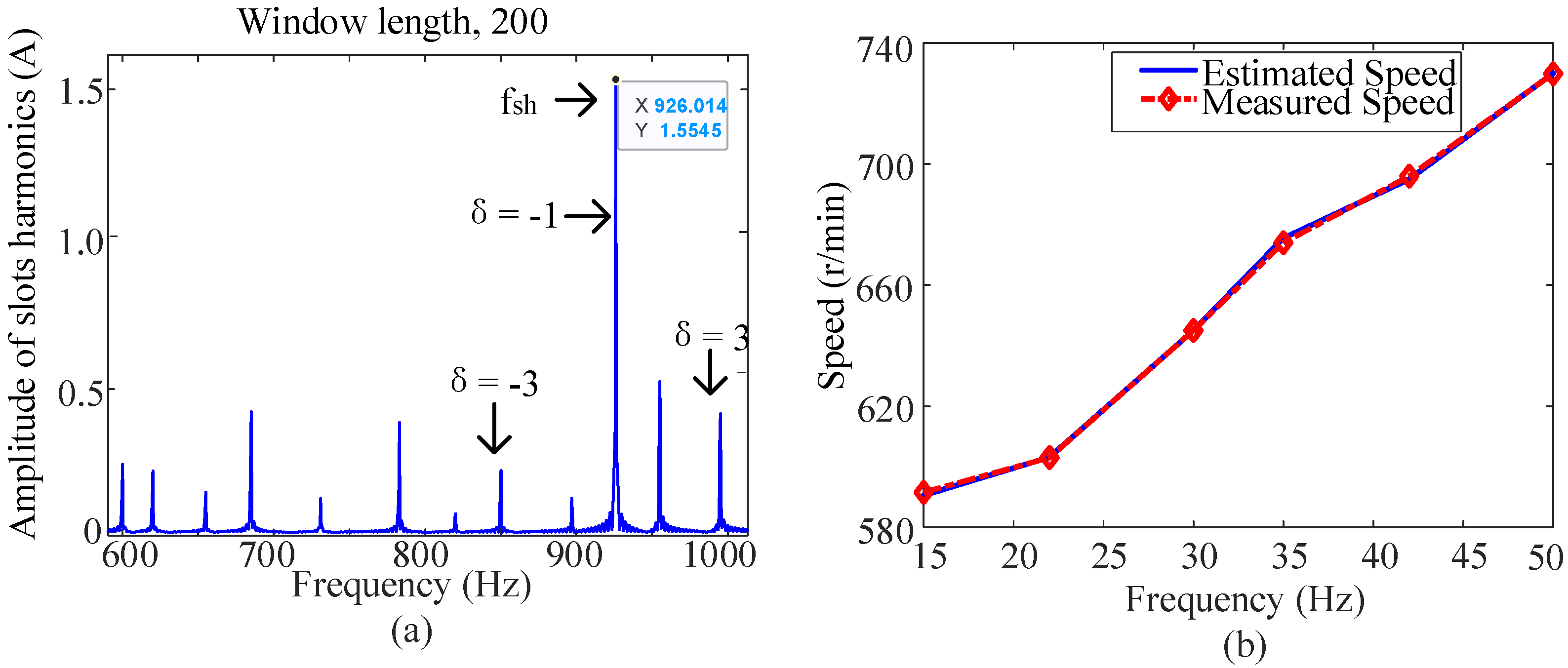
As an example, let us suppose a 32-rotor slot, 2 pole pair, 3.5% rated slip motor, and a 50 Hz supply frequency. From
Table 1, it can be seen that only PSH ideally exists at δ = 1. In light of the motor slip’s range of 0% to 3.5% and using Equation (15), the rotor slot harmonic frequency
fsh search range is determined as
fshlow = 822 Hz and
fshhigh = 850 Hz. ZISTCZT does not need to execute in this scenario because the
fsh search range is not large. The search range can be reduced in the second iteration if the slip obtained in the first one is employed. Because the motor speed will not abruptly change, neither will the slip; now, using the frequency data already determined for
f1 and
fsh, the values of the rotational speed
n are estimated using Equation (8). These results are kept, the window is slid, and the search is performed continuously until the last iteration is realized.


 ,
, 


