Article

Investigation of Heat Transfer Fluids Using a Solar Concentrator for Medium Temperature Storage Receiver Systems and Applications

1
Department of Physics, University of Rajasthan, Jaipur 302015, India
2
Materials Research Centre, MNIT, Jaipur 302017, India
3
Mechanical Engineering Department, Government Engineering College, Patan 384265, India
4
Department of Physics and Electronics, Material Science, Innovation and Modelling (MaSIM) Research Focus Area, North-West University (Mafikeng Campus), Private Bag X2046, Mmabatho 2735, South Africa
*
Author to whom correspondence should be addressed.
Energies 2022, 15(21), 7868; https://doi.org/10.3390/en15217868
Submission received: 28 September 2022 / Revised: 19 October 2022 / Accepted: 21 October 2022 / Published: 24 October 2022
(This article belongs to the Special Issue Small Scale Solar Thermal Energy Storage Systems for Rural Energy)

Abstract

:
Solar concentrator collectors have the potential of meeting the medium- and high-temperature thermal energy demands of the world. A heat transfer fluid (HTF) is a vital component of a concentrating system to transfer and store thermal energy. This paper presents the design development of a solar paraboloidal dish concentrator (SPDC) and a study of selected HTFs using the storage receiver system of the concentrator. The locally designed SPDC (diameter 1.21 m and height 0.20 m) has features like light weight, effortless tracking, convenient transportation along with high optical and thermal performance. Three HTFs, silicone oil (SO), engine oil (EO) and ethylene glycol (EG), are selected based on their favorable properties for medium temperature (150–300 °C) applications. The characteristic parameters of HTFs, heating rate (Rh), instant thermal efficiency (ηith) and the overall heat loss coefficient (UL), are illustrated and determined experimentally. A new characteristic parameter, the normalized maximum fluid temperature (Tnf), is also introduced in the paper. In the heating test, the maximum attained temperatures by fluids, SO, EO and EG are found to be 240 °C, 180 °C and 160 °C, respectively. The thermal efficiencies of SO, EO and EG are determined to be 45, 36 and 31%, respectively. The heating rate of 6.56 °C/s is found to be the maximum for SO. Through the cooling test, the overall heat loss coefficient (UL) is computed to be 14 W/mK, which is the least among the three fluids compared. The high thermal performance, environmental safety and chemical stability of silicone oil make it suitable for use in concentrators for medium-temperature heat transfer and storage applications.

1. Introduction

Solar energy can be harnessed by non-concentrating or concentrating solar thermal collectors (STC). Five main solar concentrator technologies can be identified as (i) Compound Parabolic Concentrator, (ii) Parabolic Trough Concentrator, (iii) Linear Fresnel Reflector, (iv) Parabolic dish with fixed focus, (v) and a Parabolic dish with a moving focus [1,2,3,4]. In solar concentrators, the generated heat is collected, transported and stored through a heat transfer fluid (HTF) for low to high temperature applications. The heat collection is governed by the optical and thermal parameters of a concentrator system and the properties of the selected HTF. The selection of an appropriate HTF is vital to minimize the cost of the concentrator receiver, heat exchanger and heat storage with high cyclic efficiency [2]. Water is the most common low-temperature HTF, but for medium/high temperature use, it has to undergo a phase change. A number of researchers have investigated various types of sensible HTFs for solar concentrators based on their applications (medium 100–300 °C to high temperature 300–800 °C), thermochemical properties and economic feasibility. The solar concentrator HTFs can be broadly categorized as (i) Thermal oil (Therminol VP-1, Dowtherm, Mobiltherm, Mineral oil etc.), (ii) Molten salts (HITEC, HITEC XL, solar salt, etc.), and (iii) Liquid metals (Lead-Bismuth, Liquid sodium, Eutectic etc.) and other as nanoparticle suspensions in different base HTFs (nanofluids) [5,6]. A detailed review of the HTFs for use in solar power plant is presented by Benoit et al. [5]. Different thermophysical properties and heat transfer correlations for receivers are presented in this review. The review presented by Vignarooban et al. [6] includes the current status (thermal properties and stability) of various HTFs, namely, molten salts, steam, organic fluids, thermal oils, liquid metals and air. Malviya et al. [7] conducted a review on various HTFs (sodium salt, HITEC-XL, solar salt, solar grade oil, etc.) for use in parabolic trough collector. A theoretical study of various HTFs (Therminol VP-1, Syltherm 800, Solar salt, Hitec XL and liquid sodium etc.) has also been conducted by Zaharil and Hasanuzzaman [8] for Malaysian conditions. Conroy et al. [9] have developed a theoretical model to investigate hydraulic flow properties of liquid sodium, molten salt and lead-bismuth in a CSP receiver. Trabelsi et al. [10] carried out an optimization study (namely, field size, storage system and HTFs) of a solar parabolic trough power plant through the simulation software, SAM, and concluded that molten salt is economically reasonable than the synthetic oil and Therminol VPI. An evaluation of the thermal and physical properties of liquid sodium and Hitec (that is, a mixture of KNO3, NaNO2 and NaNO3) was carried out by Boerema et al. [2]. It is found that liquid sodium is a suitable substitute for molten salts in future CSP. Kenda et al. [11] have studied Jatropha crude oil as an alternative HTF or thermal energy storage material (TES) and found that this oil is appropriate for a small CSP plant working near a temperature of 210 °C. Hoffmann et al. [12] have studied and compared different vegetable oils, namely, sunflower, soybean, jatropha, etc. in the medium temperature range for innovative HTFs/TES in CSP. The theoretical and experimental work carried out on different solar thermal systems with various sensible HTFs are summarized in Table 1. The table does not include work on nanofluids as it is not related to the present work.
Table 1 reveals that only a few references have quoted silicone oil (SO) as heat transfer fluids. An experimental investigation of Dow-corning 550 silicon oil was performed by Vignarooban et al. [6]. Good thermal characteristics, low corrosivity and flammability are some important reported features of this oil [6]. Nkwetta et al. [13] have also examined the thermal performance of Dow-corning 550 silicon oil for one non-concentrating and two concentrating evacuated tube heat pipes. Improved efficiency and high energy collection in comparison to pressurized water were reported in the paper [13]. High temperature stability of a HTF, HELISOL® from Wacker Chemie AG, which was a silicone-based HTF, was explored by Jung et al. [14]. The overheating (1000 h at 465 °C) of this fluid did not produce any coke-like product due to the PDMS (polydimethylsiloxane) base, while a degradation of DPO (diphenyl oxide)/BP (biphenyl) based fluids (namely, Therminol VP-1, Dowtherm A) was observed in the study [14]. Based on these reported studies in favor of SO as a suitable HTF for high temperature range, the present work is focused on an experimental investigation of SO using a small solar paraboloidal concentrator. The other synthetic oils, diesel engine oil and ethylene glycol (rarely tested), are also considered in the present study. The studies on small-size solar paraboloidal concentrators (diameter 1 to 2 m) are briefly presented in Table 2. This table shows that using storage receiver systems either stagnation test (empty receiver) or sensible heating test with water as the HTF is performed for testing of the concentrators. Table 1 and Table 2 illustrate that only a few references [6,13,14] have investigated different thermal properties of silicone oil, and testing was conducted on evacuated tube solar collectors (ETC). According to the reviewed literature, no study has been conducted to test the performance of SO using a paraboloidal concentrator. The other two selected synthetic oils have also not been studied. Therefore, in the present work, an experimental study is focused on these materials to find a moderate approach for practical use of these materials in medium temperature (150–300 °C) heat transfer and storage applications. The paper includes the design details, and fabrication of a solar paraboloidal dish concentrator (SPDC) based on optical performance parameters. A comparative experimental study of the selected synthetic oils is conducted on a number of days. The characteristic parameters, namely, instant thermal efficiency η i t h of the concentrator with different HTFs, heating rates (Rh) and overall heat loss coefficients (UL) of HTFs, are determined through thermal performance. A new characteristic parameter, normalized maximum fluid temperature (Tnf), is introduced in the paper. The introduced parameters are computed and based on the experimental observation, and recommendations are made for the selected HTFs.

2. Methodology

2.1. Performance Parameters of Solar Concentrator

The basic elements of a solar paraboloidal dish concentrator (SPDC) system are: (i) the reflector (ii), receiver (iii), tracking system and (iv) a storage system. The incident sunlight reflects through the reflector surface and concentrates at a receiver positioned at the focus point of the dish. The radiation is absorbed through a metallic receiver and generated heat is transferred to a HTF [1,2]. Through the circulation of HTF, heat is collected in a thermal storage system. A dual-axis tracking system is required for the proper collection of heat through the receiver. In the present case, instead of a separate storage system, a cylindrical storage receiver system is used for heat collection and storage. A dish concentrator can be characterized based on its optical and thermal performance. The optical performance is governed by the design parameters of the dish, and the properties of the reflector, while the thermal performance is influenced by the optical performance together with the receiver shape, and the properties of the receiver and HTF materials.

2.1.1. Optical Performance

The concentrator diameter (D), rim angle ( ϕ ), height (h) and focal distance (f) and local mirror radius (r) are the main responsible design parameters for optical performance (Figure 1). The relations between these parameters are following:
  f = D 2 16 h
  ϕ = sin 1 D 2 r
f = r 1 + cos ϕ 2
  r = 1 2 D 2 + 4 f h 2
The recommended rim angle for a SPDC is between 45 and 67° [1,26]. The numbers of flat reflector facets, the surface errors and the reflectivity of the material are the other influencing parameters of optical design. A finite spread of the focal point can also degrade the optical performance. For an ideal 2D parabola concentrator, the focal image width (Fw) is given as [1]:
F w = 2 a   sin δ sin ϕ cos ϕ + δ
where δ (0.267°) is the sun shape error. The design inadequacy of a dish causes a considerably large practical image width, Fpw. So, practically, the ratio of the dish aperture area, A a , to the receiver base area, A r , is defined as a characteristic optical performance parameter named as concentration ratio, Cc.
C c = A a A r = D 2 F p w 2

2.1.2. Thermal Performance

The high thermal performance of a concentrator is linked with a high optical performance and, the properties of the receiver and HTFs. The optical characteristics of the system affect the rate of available heat (qa) for thermal application. The rates of utilizable heat (qu) and the heat loss (ql) are controlled by the storage receiver system design, and the properties of the receiver and HTF materials. The energy balance equation and the instant thermal efficiency ( η i t h ) for the dish are given as [3]:
qu = qaql
qa = AaIbρ(γτα)Kγτα
ql = ArsUL(TrTa)
  q u = m r C r + m f C f Δ T f Δ t  
  η i t h = q u q a
In the above relations, if solar insolation is measured on a horizontal surface, then Ib = 0.7Issec θ is a good approximation for the location at Jaipur, where Ib is the beam insolation at the dish aperture area (W/m2), Is is the global solar insolation at the horizontal surface (W/m2), 0.7 is a direct radiation fraction and θ is the angle of incidence on the horizontal surface. Further, ρ is the specular reflectance of the concentrator, τ is the transmittance of receiver cover (if any), γ is the reflected radiation fraction at the receiver surface and α is the absorption coefficient of the absorber. The incidence angle modifier, Kγτα, includes the effects of angle of incidence on the intercept factor. If the receiver has no transparent cover, then the effect of τ and Kγτα is not considered. The overall heat loss coefficient is UL. The receiver and ambient temperatures are Tr and Ta, respectively. ΔTf is the rise in fluid temperature in the time interval Δt, Ars is the receiver total surface area, mr and mf are masses of the receiver and fluid, respectively, and, Cr and Cf are specific heats of the receiver and fluid at the constant pressure.

2.2. Characteristic Parameters of Heat Transfer Fluid

The study of a HTF using a concentrator can be performed by conducting the heating and cooling tests in the storage receiver system (SRS).

2.2.1. Heating Test

The heating rate, Rh, and instant thermal efficiency, ηith, are the heating characteristics of a HTF under the transient state. Both can be determined using the linear curve fitting between the fluid temperature, Tf, and heating time i.e., through the thermal profile of the HTF in the concentrator SRS. In the steady state, the HTF reaches to its the maximum fluid temperature, Tfm, and remains constant. In a concentrator, Tfm, can be normalized through a solar insolation value about 700 W/m2, to compare Tfm of different HTFs tested under variable insolation conditions. Therefore, in the steady state, a new parameter, normalized maximum fluid temperature, Tnf, can be introduced. Hence, following are the characteristics of heating test:
In the transient state
  R h = Δ T f Δ t
In the steady state
R h = 0
T n f = 700 T f m ¯ I b ¯
where T f m ¯ and I b ¯ are the average maximum fluid temperature and the average beam radiation, respectively, during the steady state.

2.2.2. Cooling Test

The overall heat loss coefficient, UL, of the SRS can be determined using the HTF cooling curve in absence of sun light. For this, Equation (9), the rate of heat loss q l can be re-written in the cooling mode by considering Tr equal to Tf. Accounting newton’s law of cooling, the UL can be determined as follow:
q l = A r s U L T f T a
q l = m r C r m f C f R c
  R c = d T f d t  
1 τ c = Δ R c Δ T f T a
  U L = m r C r m f C f τ c A r s  

2.3. Storage Receiver System

For an SPDC, receivers’ types are (i) external and (ii) cavity. In the external receiver, the solar flux is absorbed through the exterior material, while in the cavity, the flux is absorbed by the material located inside the cavity. Various shapes of receivers for example cylindrical, spherical, conical, etc., have been studied for concentrators. The simplest design is the external cylindrical receiver that collects the heat and also stores heat for other useful applications. The conventional receiver materials are copper, aluminum and stainless steel (Table 2). High thermal conductivity (417 W/mK) and temperature stability (1084 °C), and moderate density (8940 kg/m3) are some appropriate properties of copper for use in high temperature concentrator receivers. However, its high cost (INR 500/kg) limits its use in low and medium temperature concentrators. High temperature stability (1510 °C); moderate density (7500 kg/m3) and low price (INR 190/kg) are good features of a stainless-steel receiver, but the poor thermal conductivity (14.4 W/mK) limits its applications in solar collectors. Good thermal conductivity (237 W/mK) and stability (660 °C) and low density (2712 kg/m3) and low price (INR 200/kg) make aluminum the most applicable receiver material for the use in low to medium temperature concentrators.

3. Designing of the Solar Dish Concentrator

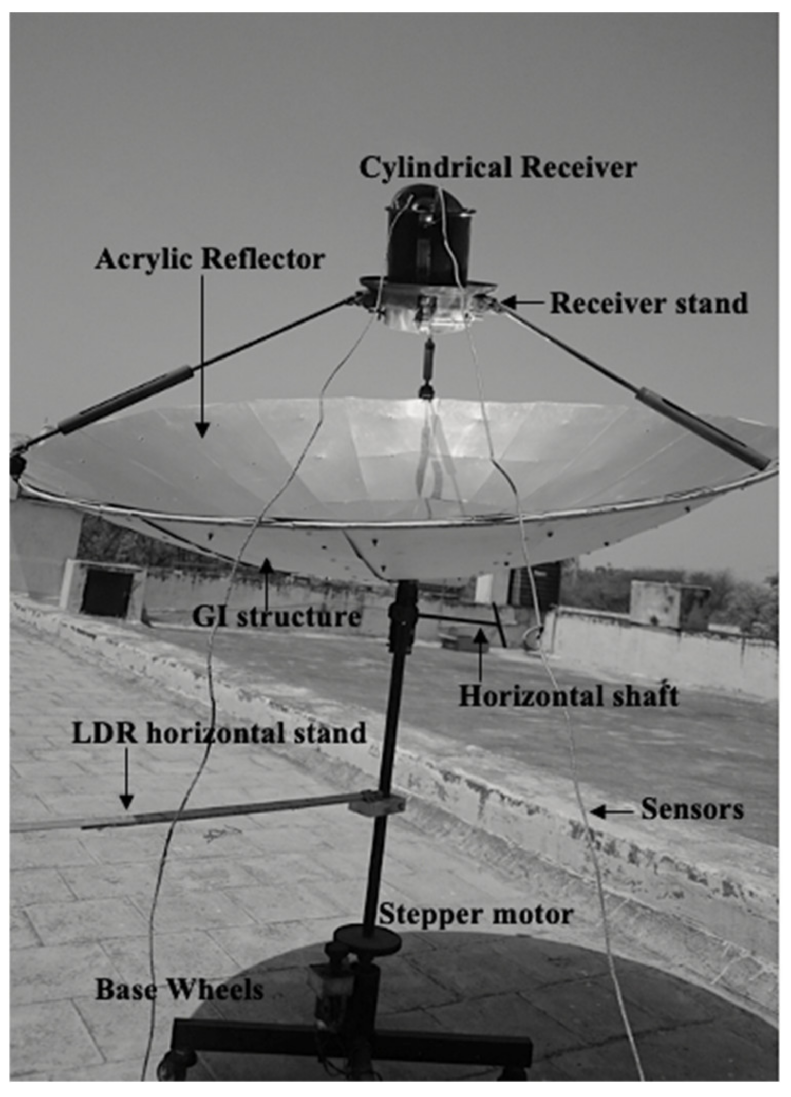
A small solar paraboloidal dish concentrator was locally fabricated at the Solar Energy Research Laboratory (SERL), University of Rajasthan, Jaipur [3,24]. The design parameters of the dish are taken as per Equations (1)–(5). The diameter of the dish is 1.21 m. For design ease, the paraboloidal curvature is kept shallow by maintaining a large rim angle of 67°. Accordingly, the height and the focal length of the dish are 0.20 m and 0.45 m, respectively. The focal image width for these parameters is 0.016 m for an ideal condition as per Equation (4). However, in a practical scenario, a finite spread of 0.12 m at the focus is observed. The dish consists of a paraboloidal base structure of Galvanized Iron (GI) sheets, a mounting pipe, a receiver stand, a jack system, two sensor-based gear systems and four base wheels. The details of the components are shown in Figure 2. The complete system is light in weight and easy to transport through the four base wheels.

3.1. Paraboloidal Structure

About 17 trapezoid lightweight polymer acrylic reflector sheets are pasted and fixed on the GI sheets. The height of a trapezoid sheet is 0.58 m, and the top and bottom parallel side lengths are 0.225 m and 0.025 m, respectively. Good reflectivity (80%), high flexibility, good temperature stability, and light weight are the important features of an acrylic reflector. The Galvanized Iron structure is bolted on a vertical pole having an elevation tracking arrangement.

3.2. Tracking

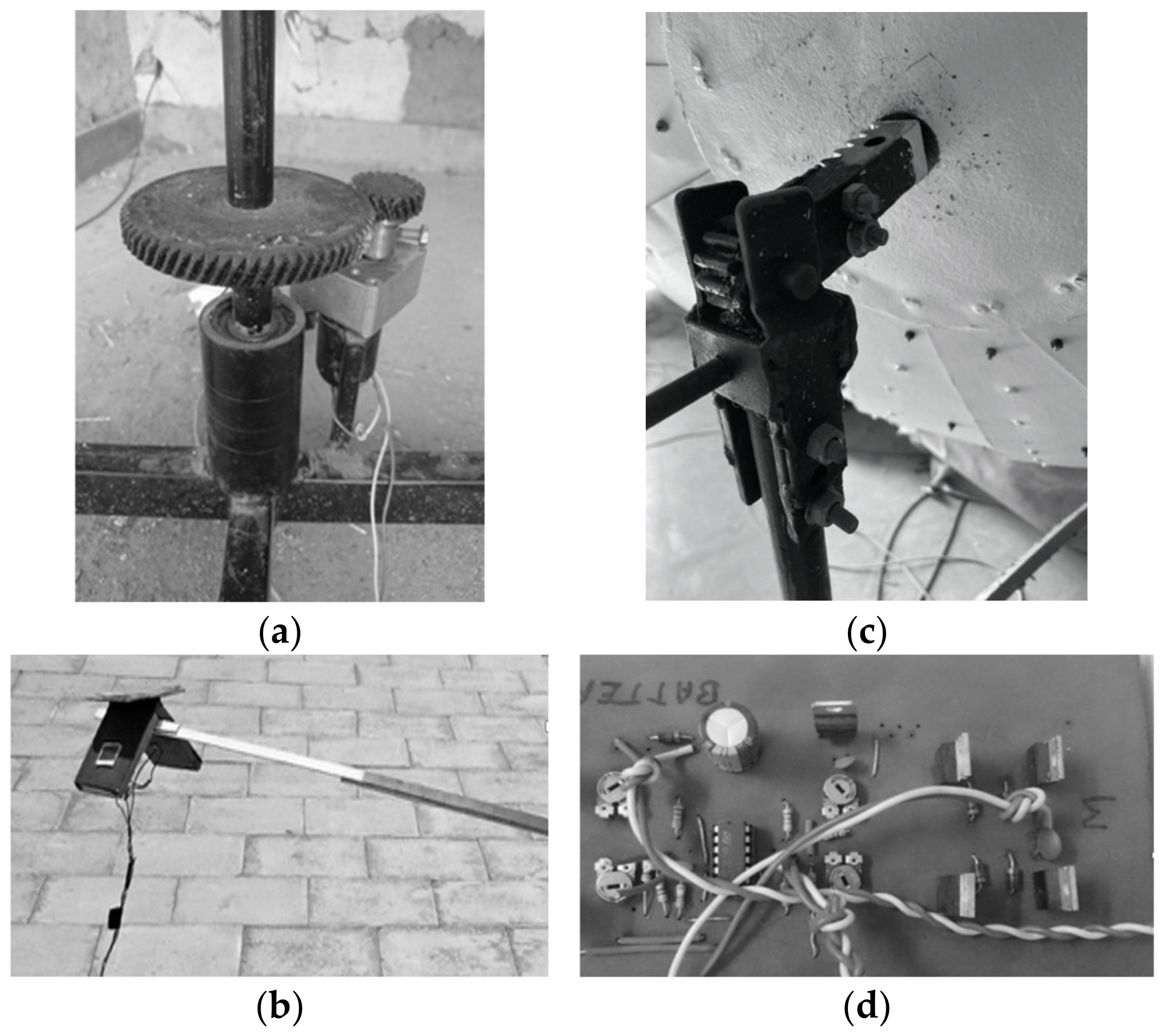
For the azimuthal (east to west) tracking, a solar tracker is mounted horizontally between a couple of vertical poles with a central movable axis, Figure 3a. When this horizontal stepper motor (gear mechanism) rotates, the entire dish shifts proportionately about its central pivot, either towards the east or west to track the sun. A set of light-dependent resistors (LDRs) are positioned on a horizontal stand connected to a central movable axis, Figure 3b. This horizontal stand is sufficiently apart from the main structure to provide clear solar radiation signals to LDRs. The LDR signals are received, compared and interpreted by an electronic circuit (consisting of a single IC 324 and two Op-amps) that commands the motor for the azimuthal tracking of the sun. The circuit configuration is shown in Figure 3d. For the altitude/elevation tracking, a jack mechanism is provided just below the paraboloidal structure shown in Figure 3c. The elevation angle is adjusted manually through the motion of a horizontal shaft attached to the jack system.

3.3. Receiver

For this comparative study of HTFs, a simple cylindrical aluminum exterior receiver is used based on the suitable properties of aluminum for medium temperature applications described in Section 2.3. The receiver diameter and height are 0.12 m and 0.175 m, respectively. The weight and maximum fluid capacity are 0.2 kg and 1.2 L, respectively. The base area, Ar, is 0.011 m2, so the concentration ratio, CC, is about 100. The receiver is two layers quoted with black matt paint with an absorptivity of 0.90. The receiver is closed with a lid having two holes to insert sensors. The total surface area, Ars, of this cylindrical receiver is 0.088 m2. The receiver is mounted on a circular receiver stand which is attached to the Galvanized Iron structure using the 3 metallic rods. The lengths of roads are adjustable, and they provide the facility to locate the receiver at the desired position.

4. Selection of HTFs

The selection of an appropriate HTF for solar dish concentrator is based on various physical and chemical properties of a fluid which include: (i) a boiling temperature higher than 150 °C for use in medium temperature applications, (ii) good thermal conductivity for fast heat collection and rejection, (iii) good specific heat for heat storage purposes, (iv) low viscosity for easy fluid motion, (v) low density for a lighter HTF unit, (vi) not toxic or environmentally hazardous and (vii) economically viable. The current state-of-art in introduction reports that various sensible heat transfer fluids have been tested and studied but studies of silicon oil (SO) and ethylene glycol (EG) are limited for concentrator applications, whereas engine oil (EO) has been barely studied. Therefore, based on the local availability and appropriate HTF properties, three HTFs, silicone oil (SO), engine oil (EO) and ethylene glycol (EG) are used for the present study. The properties of these HTFs are listed along with water (a low-temperature HTF) and Therminol 66 (a high-temperature HTF) in Table 3. The suitability of these fluids is supported by various properties mentioned in the table. Therminol 66 is mostly the preferred HTF, but the high cost of this fluid limits its usage in medium temperature applications not economically viable. Table 3 presents a comparison of selected fluids and their properties with Therminol 66. This comparative study favors the suitability of SO, EO and EG for medium temperature applications. All these HTFs have a boiling temperature higher than 170 °C. The thermal conductivities, specific heats and densities are within an acceptable range. The significantly high viscosity of SO, and toxicity of EO and EG are some constraints for their usage. Nevertheless, the present experimental study is conducted to investigate their thermal properties. Water is a low temperature HTF; however, in this comparative experimental study, it is also considered. The ethylene glycol (HELISOL®) is 99% pure, purchased from Merck Life Science Pvt. Ltd. The silicon oil (350 CST) is purchased from Ases Chemicals works and Diesel engine oil (20W-40) is made by Hindustan petroleum Cor. Ltd., Mumbai, India

5. Experimental Study

5.1. Test Set-Up

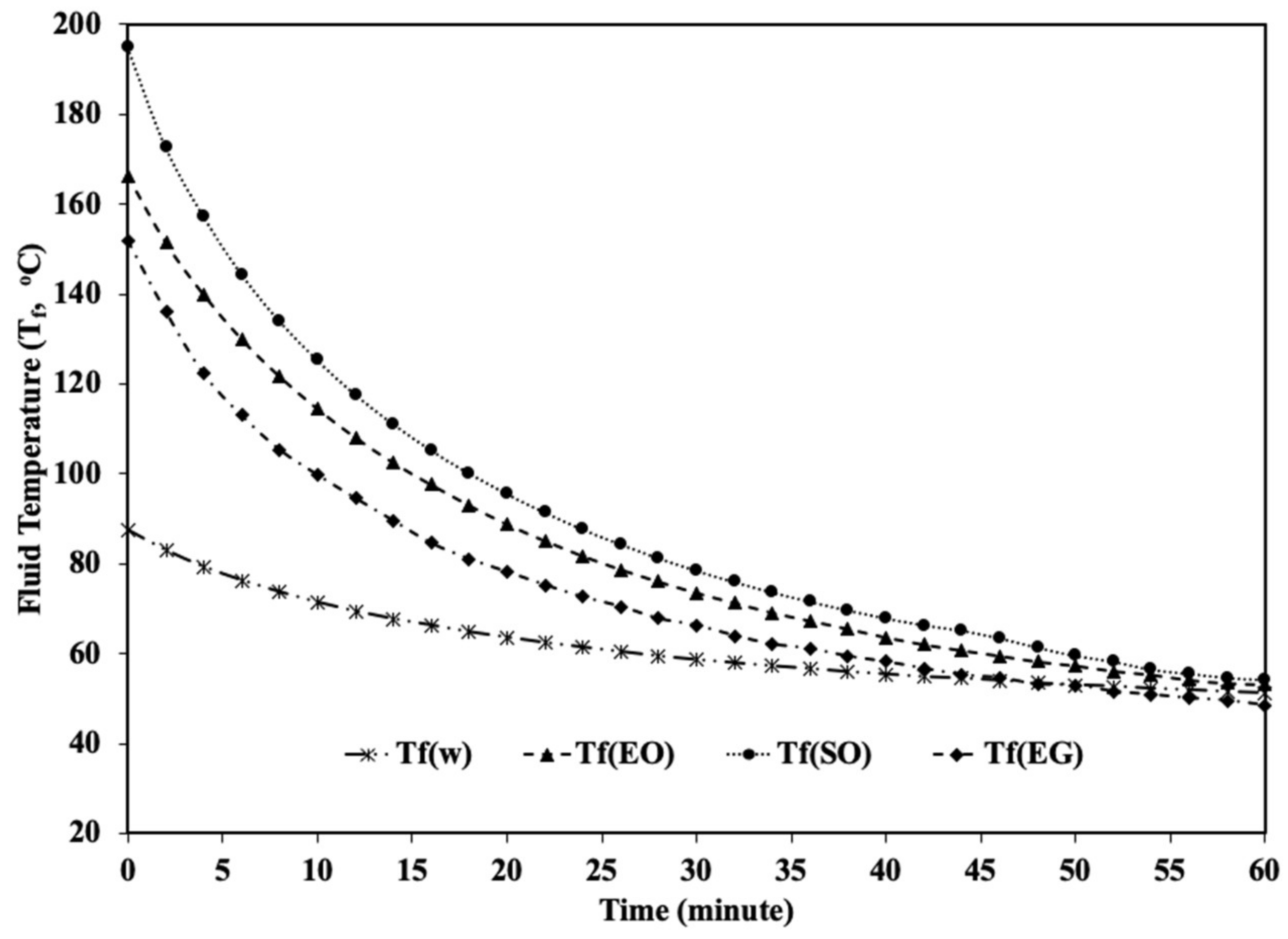
The sensible heating tests for all the HTFs were conducted at the SERL, Jaipur (26.92° N, 75.87° E). The experiments were carried out for a period around local noon, i.e.,11:00 am to 01:00 pm Indian Standard Time (IST) in the month of November 2021. The amount of each HTF was 0.5 L in the cylindrical aluminum receiver. The receiver was covered with a lid and two K-type temperature sensors (range −10 °C to 600 °C) were dipped in the fluid through holes in the lid for fluid temperatures (Tf1 and Tf2) measurement. One sensor was also adjusted at the bottom of the receiver for the base temperature (Tb) measurement. These K-type sensor temperatures were attached to a data logger (Masibus 85XX+, least count 0.1 °C). The data logger is connected to a computer that uses mSCAN+ software to display and record the data in every 5-min interval. The solar insolation (Is, accuracy ± 5 W/m2) on the horizontal surface and the ambient temperature (Ta, accuracy ±   0.1 °C) were recorded by a weather station (Virtual hydromet). The manual elevation tracking of the dish concentrator was performed at 15-min intervals and the azimuthal tracking was controlled by an LDR tracking circuit. The cooling test was performed just after the completion of the heating experiment. For this, the dish is moved to a shaded place and the receiver was removed from the receiver stand to avoid conduction losses. The receiver was kept in the shaded open environment of similar ambient temperature conditions of the heating test and the fluid temperatures were measured at 2-min intervals for the 1 h duration.

5.2. Thermal Profiles

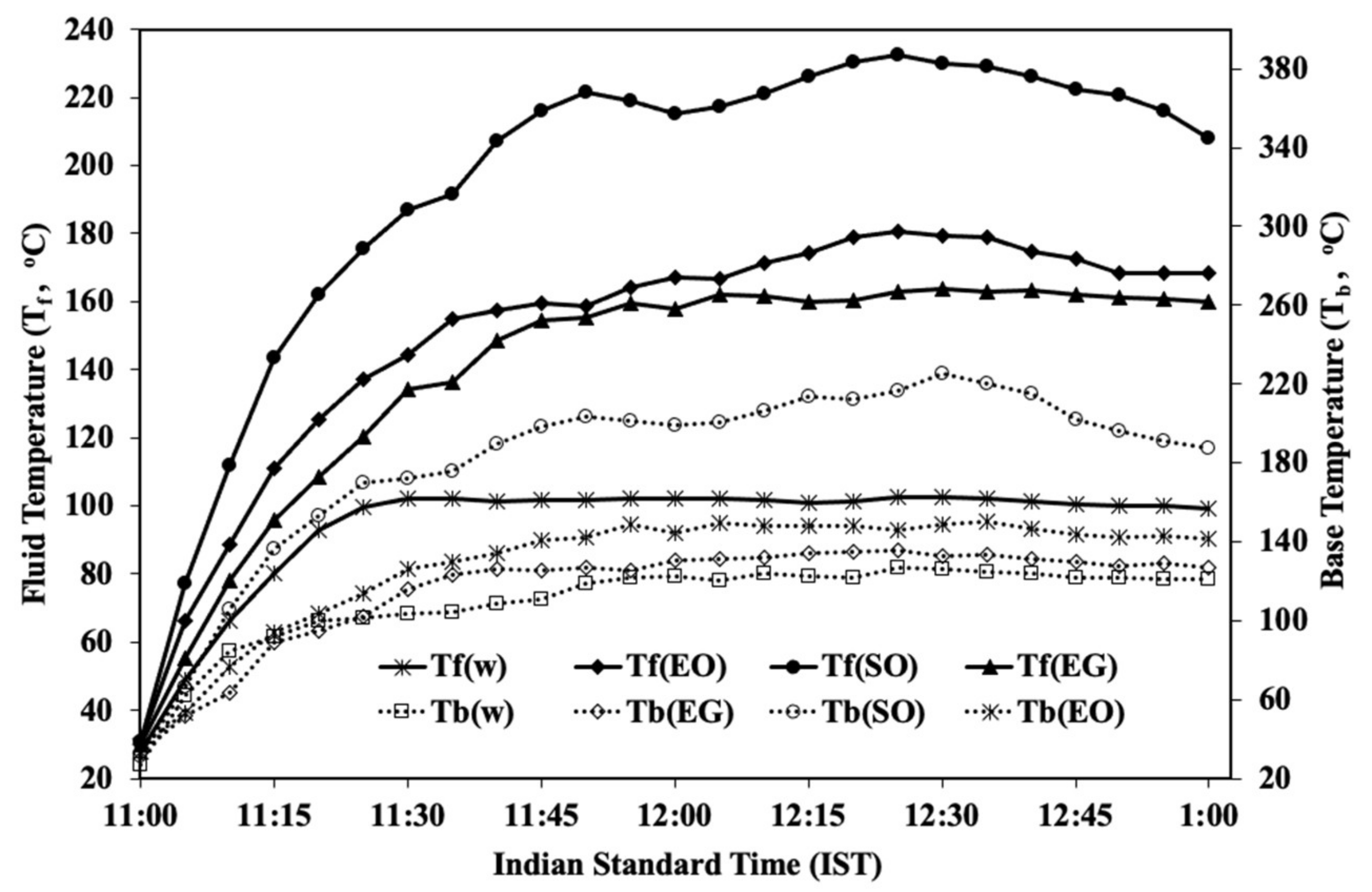
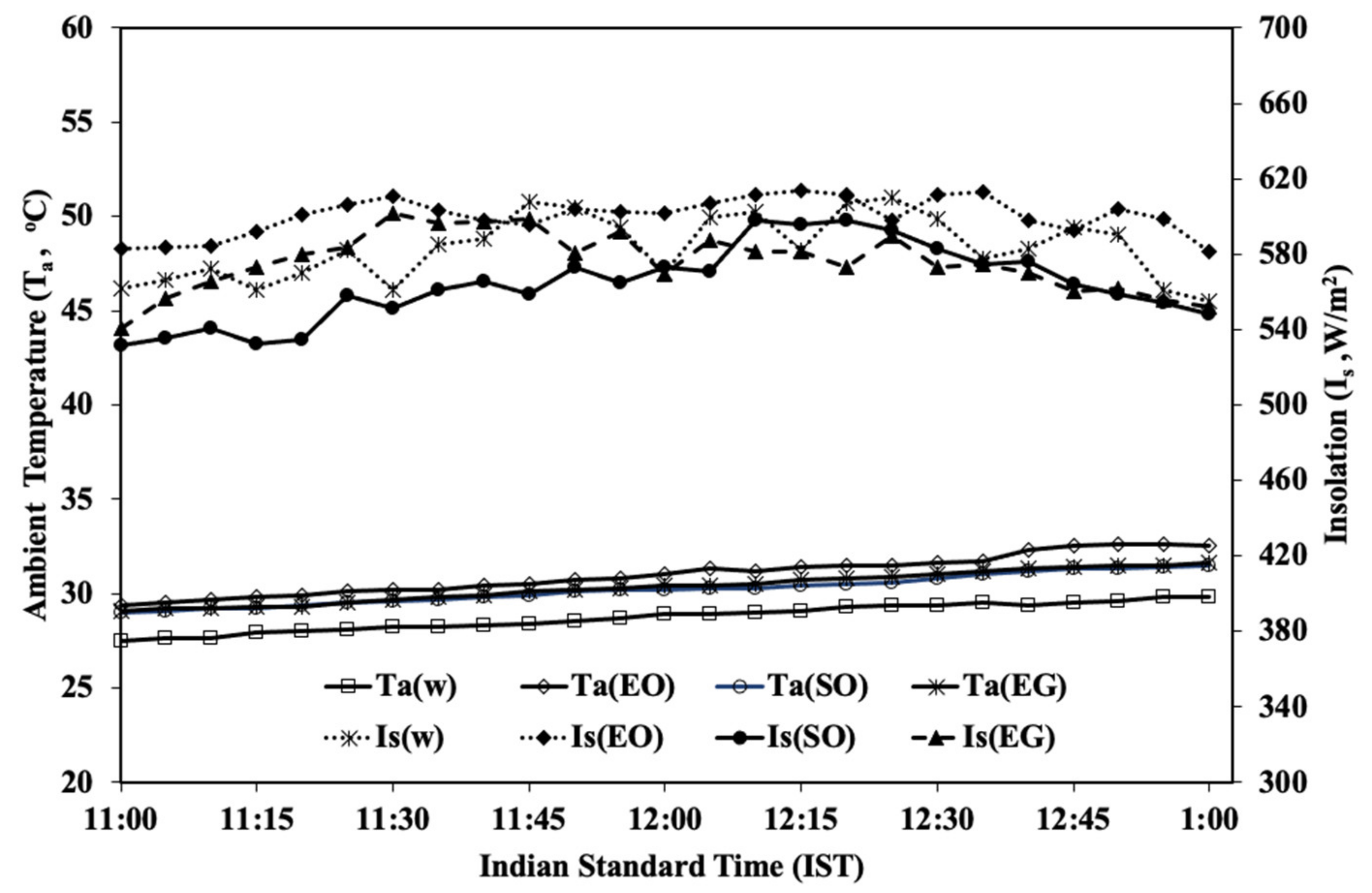
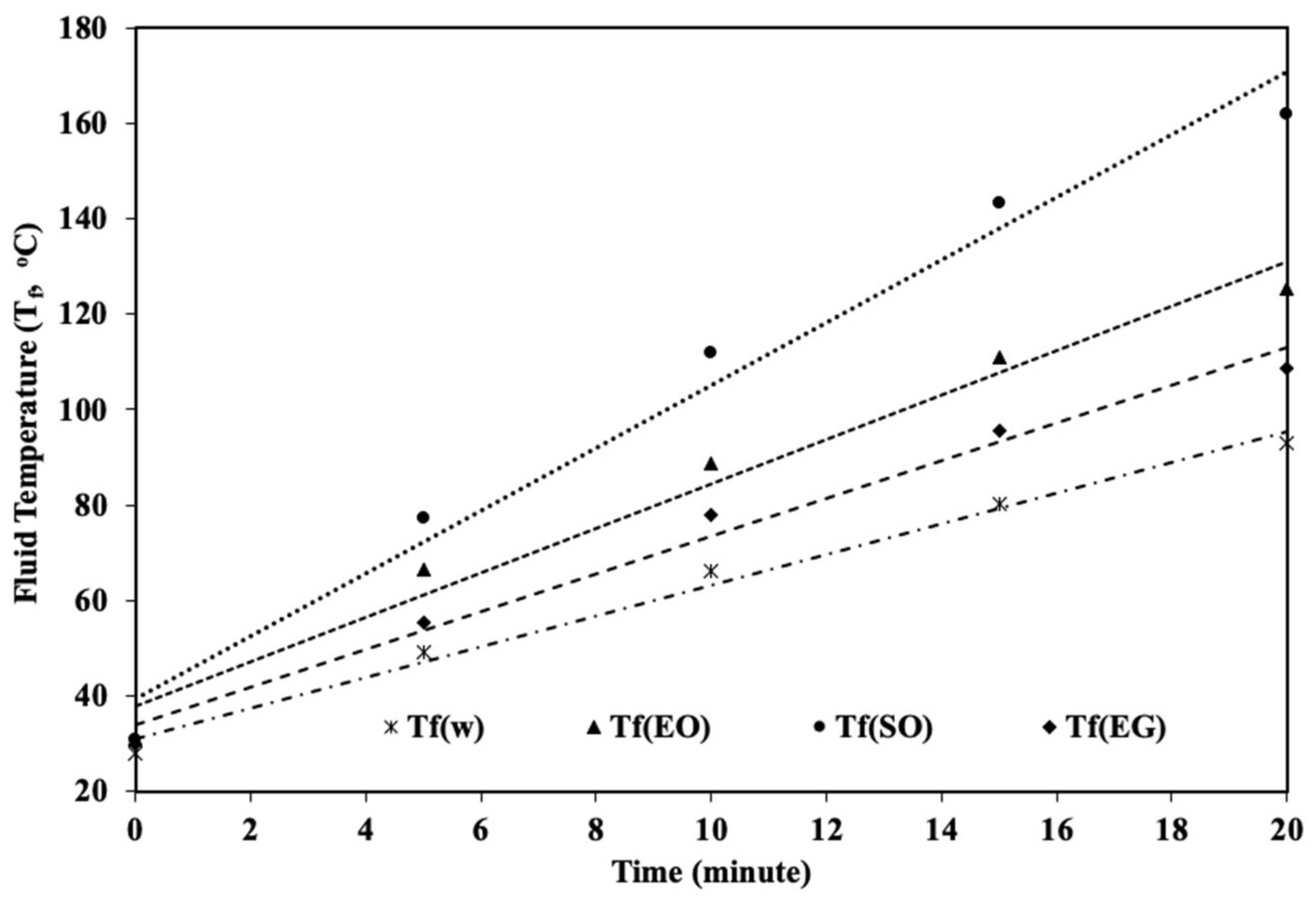
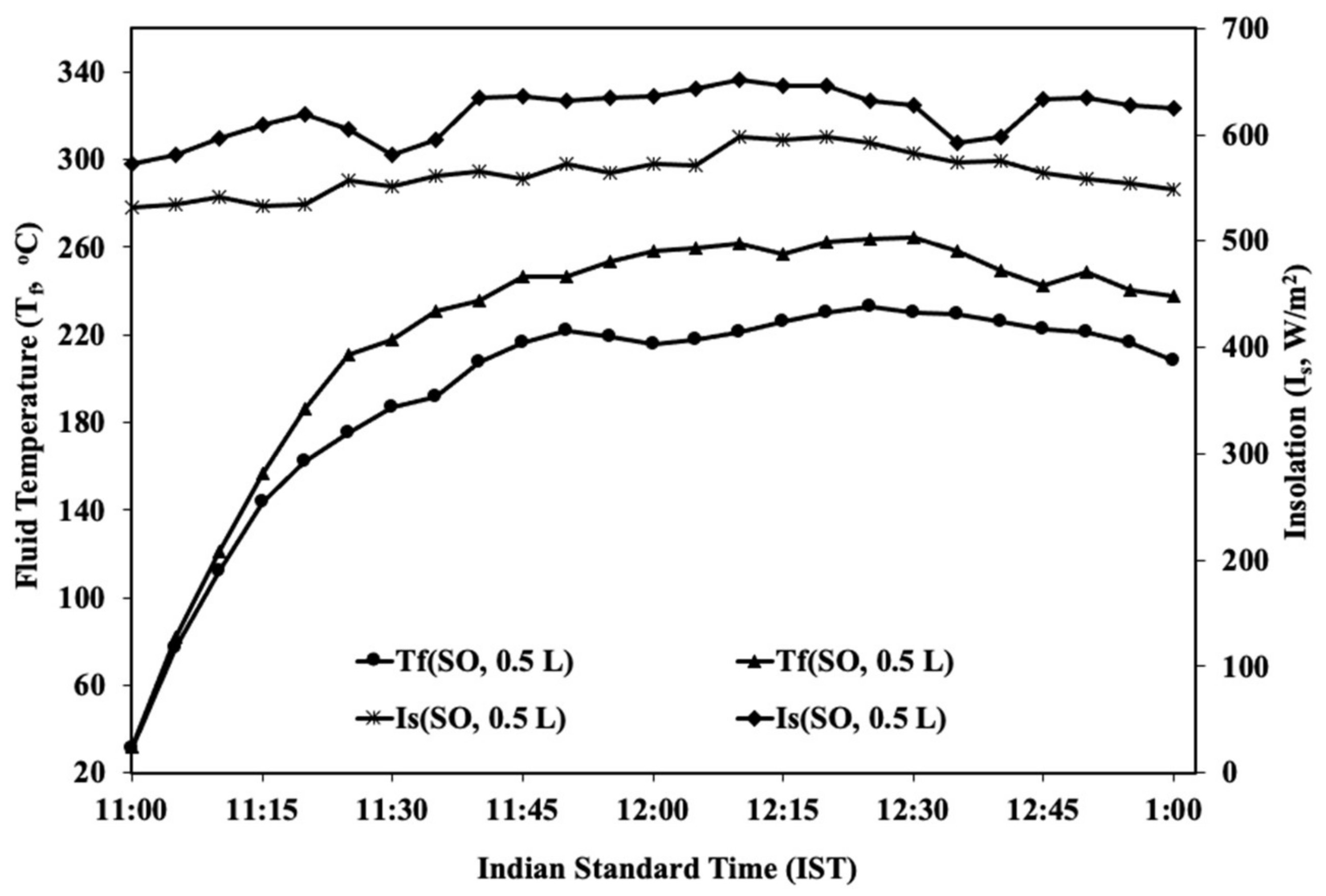
The experiments were conducted on a number of days with similar weather conditions of the insolation and ambient temperature within the range of 570 ± 40 W/m2 and 29 ± 2 °C, respectively, for this comparative study. The measured base temperatures (Tb) and the average fluid temperatures (Tf) on the sunny days are shown in Figure 4. The experimental days for EO, EG, SO and water were 15 November, 17 November, 20 November and 23 November 2021, respectively. These nearby days provided similar weather conditions for comparison. The variation of solar insolation (Is) and the ambient temperature (Ta) at Indian standard time (IST) on different experimental days are depicted in Figure 5. The fluid capacity is 0.5 L in each experiment. In the transient states, the heating curves of the HTFs are shown in Figure 6. The cooling curves of HTFs are plotted in Figure 7. To examine the effect of high solar insolation, a test with 0.5 L SO is also conducted on a high insolation day. The thermal profile of this test is plotted in Figure 8.

6. Result and Discussion

6.1. Thermal Performance of the Developed Concentrator

Figure 4 illustrates that in the transient state, the temperatures of fluids increase at a good rate (3.21 to 6.56 °C/s) and temperatures reach a steady state (100 to 230 °C). As the solar insolation decreases in the afternoon hours, the fluid temperature slightly decreases. The transient state time varies for different fluids, but an effective transient time of 20 min can be considered to determine the rate of heating. The highest fluid temperature is about 230 °C, corresponding to the solar insolation of 550 W/m2. The thermal efficiency for water load is found to be 41%, which is near to the efficiency values quoted in Table 2 references [20,21]. It reflects the good thermal performance of the concentrator for low to medium-temperature solar thermal applications via a suitable heat transfer fluid. No sudden decrease or increase is observed in the thermal profiles, indicating the appropriate working of the LDR-based tracking system on sunny days.

6.2. Characteristics of HTFs

The base and fluid temperatures of the storage receiver system are depicted in Figure 4 for the selected fluids. The solar insolation and ambient temperature variations on these experimental days are shown in Figure 5. The solar insolation and the ambient temperature variations are in the range of about 570 ± 40 W/m2 and 29 ± 2 °C, respectively, on the test days. These considerably small variations provide an identical condition to compare the performance of selected HTFs. Figure 4 clearly depicts that the silicone oil temperature reaches near 230 °C which is much higher than any other fluid. The highest temperatures for other HTFs, engine oil, ethylene glycol and water, are 180 °C, 160 °C and 100 °C, respectively. The ambient temperatures remained close to each other for all the experimental days. From Figure 5, the insolation values corresponding to the highest temperatures of all fluids are within a variation of about 595 ± 10 W/m2. The heating curves in the transient time period of 20 min are plotted in Figure 6. In the initial 20 min, the temperatures attained by SO, EO, EG and water are 162, 125, 109 and 93 °C, respectively. This figure depicts that the highest rate of fluid temperature rise occurred for silicone oil. The cooling curves of all fluids are depicted in Figure 7. In the cooling tests, the temperatures of SO, EO, EG and water decreased at different rates and reached near 50 °C after one hour. The heating and cooling characteristic parameters are determined using Figure 4, Figure 5, Figure 6 and Figure 7 and Equations (7)–(18), and are given in Table 4 and Table 5. For this computation, γ is taken as 0.8 and the average value of θ is considered to be 48° for noon time in the month of November. The properties of fluids are taken from Table 3 for the computation of the rates of utilizable heat. Table 4 infers that the rates of the available heat differ within 395 ± 25 W which offers similar weather conditions to compare the characteristic parameters. Using the values of the rates of heat available and utilizable, the instant efficiency of each fluid is computed. The instant efficiency is found to be 43% for silicone oil (SO), while EO, EG and water have efficiencies of 36%, 31% and 41%, respectively. Water has good efficiency for low temperature applications. Table 5 contains the heating and cooling characteristics of HTFs. In this table, Rg represents the regression coefficient of the heating curve in the transient state and the linear curve between Rc and TfTa in the cooling test. The ambient temperature for the cooling test is considered to be the same for one hour. The ambient temperature values were near 31.5, 32.5, 31.6 and 29.8 °C during the cooling tests of SO, EO, EG and water, respectively. All the linear curves have Rg greater than 0.90, showing good approximations for linear relationships. The heating rate of a HTF (Rh), 6.56 °C/s, is found to be maximum for SO (due to low specific heat) and minimum 3.21 °C/s for water (due to the highest specific heat). The normalized maximum fluid temperature, Tnf, is determined to be 274 °C for SO from the thermal profile on 20 November. From Figure 8, the average fluid temperature attained by SO is 254 °C at the average insolation of 630 W/m2 on 9 November 2021 and the Tnf is found to be 282 °C. These values of, Tnf, on 20 November and 9 November are within the range of 278 ± 4 °C, so the normalized maximum fluid temperature can be a characteristic of any HTF. The overall heat loss coefficient, UL, during cooling is found 14 W/mK for SO, which is the lowest compared to the other fluids. This is due to the increase in the specific heat of SO from 1.7 kJ/kg°C (at 50 °C) to 2.1 kJ/kg°C (at 250 °C).
Hence, the transient ηith, Rh, and the steady state heating characteristics, Tnf, are found to be highest, and the cooling characteristics UL is found to be lowest for silicone oil. The physical appearance of all the fluids before heating and after heating was checked. No significant color changes or viscosity changes were observed for SO and EG, but for EO, slight changes were observed. The costs of EO and EG are lower than the SO, but it is observed during experiments that EO and EG have strong fume issues while no such problem is noticed for SO. Overall, based on characteristics parameters and physical and chemical properties, SO is found to be the most suitable HTF for medium temperature solar concentrators for heat transfer and storage applications.

7. Conclusions

The selection of an appropriate heat transfer fluid (HTF) for a solar concentrator enhances its efficiency. This selection depends on the temperature range and physical and chemical stability, together with the economic feasibility of the HTF. Presently, a paraboloidal solar dish concentrator is designed and developed with some attractive features and the thermal performance is tested using four selected HTFs, which are: Silicone oil (SO), Engine Oil (EO), Ethylene Glycol (EG) and Water (W). The characteristic parameters of the thermal efficiency, rate of heating and rate of heat loss coefficient are theoretically explained in the paper and experimentally determined for each HTF. A new characteristic parameter “normalized maximum fluid temperature”, provides a way to investigate the generated temperature in similar solar insolation conditions. It is found that the Silicone oil (SO) has a maximum heating rate 6.56 °C/s and a normalized maximum fluid temperature of 274 °C. The overall heat loss coefficient is determined to be a minimum of 14 W/mK for SO. Therefore, the present work suggests Silicone oil as the most suitable HTF for medium temperature heat transfer and storage applications.

Author Contributions

S.K.: Experimental investigation, theoretical data collection, resources and drafting. P.K.K.: Investigation and data collection. M.S.K.: Investigation, data collection and resources. H.P.: Resources, review and editing. A.M.: Technical amendment, formal analysis, visualization, expert language suggestions, review and editing. S.M.: Methodology, technical analysis, conceptualization, writing original draft and supervision. All authors have read and agreed to the published version of the manuscript.

Funding

Department of Science and Technology (Project No. DST/TMD/SERI/S91), Science and Engineering Research Board (Project No. EEQ/2018/000811).

Acknowledgments

This research is carried out at the solar energy research laboratory (SERL), Department of Physics, University of Rajasthan, Jaipur as a part of two project works, and these projects (DST/TMD/SERI/S91 and EEQ/2018/000811) are funded by the Department of Science and Technology (DST) and Science and Engineering Research Board (SERB), New Delhi, India. Pawan Kuldeep and Sandeep Kumar are thankful to UGC, New Delhi, India for providing fellowships to them to carry out this research work.

Conflicts of Interest

The authors declare that they have no known competing financial interests or personal relationships that could have appeared to influence the work reported in this paper. All of the sources of funding for the work described in this publication are acknowledged. It is confirmed that the manuscript has been read and approved by all named authors and the order of authors listed in the manuscript has been approved by all named authors.

Nomenclature

αabsorption coefficient of the absorber
γreflected radiation fraction at the receiver surface
δ sun shape error (°)
η i t h instant thermal efficiency
θangle of incidence on the horizontal surface (°)
ρspecular reflectance of the concentrator
τtransmittance of receiver cover material
τccooling time characteristic (s)
ϕ rim angle (°)
A a dish aperture area (m2)
A r receiver base area (m2)
Arsreceiver total surface area (m2)
Ccconcentration ratio
Cfspecific heat of fluid at the constant pressure (J/kg°C)
Crspecific heat of receiver (J/kg°C)
Dconcentrator diameter (m)
Fwfocal image width (m)
Fpwpractical focal image width (m).
ffocal distance (m)
hheight (m)
Ibbeam radiation at dish aperture area (W/m2),
Isglobal solar insolation on horizontal surface (W/m2),
Kγταincidence angle modifier
mrreceiver mass (kg)
mffluid mass (kg)
qarate of available heat (W).
qurate of utilizable heat (W)
qlrate of heat loss (W)
rlocal mirror radius (m)
Rhheating rate of HTF (°C/s)
Rccooling rate of HTF (°C/s)
Tffluid temperature (°C)
Tfmmaximum fluid temperature (°C)
Tnfnormalized maximum fluid temperature (°C)
Trreceiver temperature (°C)
Taambient temperature (°C)
ΔTfrise in fluid temperature in the Δt time interval (°C)
ULoverall heat loss coefficient (W/mK),
CSPconcentrated solar power
EGethylene glycol
EOengine oil
HTFheat transfer fluid
LDRlight-dependent resistor
SOsilicone oil
SPDCsolar paraboloidal dish concentrator
STCsolar thermal collector
STSsolar thermal systems
SRSstorage receiver system
TESthermal energy storage

References

  1. Duffie, J.A.; Beckman, W.A. Solar Energy Thermal Processes; New York John Willy and Sons: Hoboken, NJ, USA, 1974. [Google Scholar]
  2. Boerema, N.; Morrison, G.; Taylor, R.; Rosengarten, G. Liquid sodium versus Hitec as a heat transfer fluid in solar thermal central receiver systems. Sol. Energy 2012, 86, 2293–2305. [Google Scholar] [CrossRef]
  3. Mahavar, S.; Bhardwaj, A.; Dashora, P. Fabrication and testing of a light weight solar concentrator. Int. J. Solid State Mater. 2016, 2, 1–9. [Google Scholar]
  4. Mahavar, S.; Khan, M.S.; Yadav, T. Synthesis, Characterization and Testing of Black Metal Oxide Nanoparticles as Solar Concentrator Receiver Material. Mater. Today Proc. 2019, 8, 22–27. [Google Scholar] [CrossRef]
  5. Benoit, H.; Spreafico, L.; Gauthier, D.F. Review of heat transfer fluids in tube receivers used in concentrating solar thermal systems: Properties and heat transfer coefficients. Renew. Sustain. Energy Rev. 2016, 55, 298–315. [Google Scholar] [CrossRef]
  6. Vignarooban, K.; Xu, X.; Arvay, A.; Hsu, K.; Kannan, A.M. Heat transfer fluids for concentrating solar power systems-A review. Appl. Energy 2015, 146, 383–396. [Google Scholar] [CrossRef]
  7. Malviya, R.; Agrawal, A.; Baredar, P.V. A Comprehensive review of different heat transfer working fluids for solar thermal parabolic trough concentrator. Mater. Today Proc. 2021, 46 Pt 11, 5490–5500. [Google Scholar] [CrossRef]
  8. Zaharil, H.A.; Hasanuzzaman, M. Modelling and Performance Analysis of Parabolic Trough Solar Concentrator for Different Heat Transfer Fluids under Malaysian Condition. Renew. Energy 2020, 149, 22–41. [Google Scholar] [CrossRef]
  9. Conroy, T.; Collins, M.N.; Fisher, J.; Grimes, R. Thermohydraulic analysis of single phase heat transfer fluids in CSP solar receivers. Renew. Energy 2018, 129 Pt A, 150–167. [Google Scholar] [CrossRef]
  10. Trabelsi, S.E.; Qoaider, L.; Guizani, A. Investigation of using molten salt as heat transfer fluid for dry cooled solar parabolic trough power plants under desert conditions. Energy Convers. Manag. 2018, 15, 253–263. [Google Scholar] [CrossRef]
  11. Kenda, E.S.; Edem, K.; Tsoukpoe, N.; Igor, W.K.O.; Coulibaly, Y.; Xavier, P.; Marie, F.; Armel, W. Jatropha curcas crude oil as heat transfer fluid or thermal energy storage material for concentrating solar power plants. Energy Sustain. Dev. 2017, 40, 59–67. [Google Scholar] [CrossRef]
  12. Hoffmann, J.F.; Vaitilingom, G.; Henry, J.F.; Chirtoc, M.; Olives, R.; Goetz, V. Temperature dependence of thermophysical and rheological properties of seven vegetable oils in view of their use as heat transfer fluids in concentrated solar plants. Sol. Energy Mater. Sol. Cells 2018, 178, 129–138. [Google Scholar] [CrossRef]
  13. Nkwetta, D.N.; Smyth, M.; Zacharopoulos, A.; Hyde, T. Experimental performance analysis and optimization of medium temperature solar thermal collectors with silicon oil as a heat transfer fluid. Int. J. Energy Res. 2013, 37, 570–581. [Google Scholar] [CrossRef]
  14. Jung, C.; Dersch, J.; Nietsch, A.; Senholdt, M. Technological Perspectives of Silicone Heat Transfer Fluids for Concentrated Solar. Power Energy Procedia 2015, 69, 663–671. [Google Scholar] [CrossRef] [Green Version]
  15. Peng, Q.; Ding, J.; Wei, X.; Yang, J. The Preparation and Properties of Multi-Component Molten Salts. Appl. Energy 2010, 87, 2812–2817. [Google Scholar] [CrossRef]
  16. Qoaider, L.; Thabit, Q.; Kiwan, S. Innovative Sensible Heat Transfer Medium for a Moving Bed Heat Exchanger in Solar Central Receiver Power Plants. Appl. Sol. Energy 2017, 53, 161–166. [Google Scholar] [CrossRef]
  17. Perez-Tavernier, J.; Vallejo, J.P.; Cabaleiro, D.; Fernandez-Seara, J.; Lugo, L. Heat transfer performance of a nano-Enhanced propylene glycol:water mixture. Int. J. Therm. Sci. 2019, 139, 413–423. [Google Scholar] [CrossRef]
  18. Sandhya, J.; Venkatraj, V. Effect of various heat transport fluids on central receiver solar thermal power plant. Mater. Today Proc. 2019, 16 Pt 2, 314–320. [Google Scholar]
  19. Quederni, A.R.E.; Salah, M.B.; Askri, F.; Nasrallah, M.B.; Aloui, F. Experimental study of a parabolic solar concentrator. Revue des Energies Renouvelables 2009, 12, 395–404. Available online: https://www.cder.dz/download/Art12-3_6.pdf.
  20. Mohammed, I.L. Design and development of a parabolic dish solar water heater. Int. J. Eng. Res. Appl. 2012, 2, 822–830. [Google Scholar]
  21. Omara, Z.M.; Eltawil, M.A. Hybrid of solar dish concentrator, new boiler and simple solar collector for brackish water desalination. Desalination 2013, 326, 62–68. [Google Scholar] [CrossRef]
  22. Subramani, J.; Nagarajan, P.K.; Subramaniyan, C.; Anbuselvan, N. Performance studies on solar parabolic dish collector using conical cavity receiver for community heating applications. Mater. Today Proc. 2021, 45 Pt 2, 1862–1866. [Google Scholar] [CrossRef]
  23. Hassan, A.; Quanfang, C.; Abbas, S.; Lu, W.; Youming, L. An experimental investigation on thermal and optical analysis of cylindrical and conical cavity copper tube receivers design for solar dish concentrator. Renew. Energy 2021, 179, e1849–e1864. [Google Scholar] [CrossRef]
  24. Mahavar, S.; Goyal, A.; Balakin, B.V. Investigation of a Solar Concentrator for Water Distillation. In Advances in Thermal Engineering, Manufacturing, and Production Management. ICTEMA 2020. 2021. Lecture Notes in Mechanical Engineering; Ghosh, S.K., Ghosh, K., Das, S., Dan, P.K., Kundu, A., Eds.; Springer Nature Singapore Pte Ltd.: Singapore. [CrossRef]
  25. Kumar, V.; Yadav, A. Experimental investigation of parabolic dish concentrator with various sizes of receiver. Mater. Today Proc. 2021, 44, 4966–4971. [Google Scholar] [CrossRef]
  26. Reddy, K.S.; Veershetty, G.; Vikram, T.S. Effect of wind speed and direction on convective heat losses from solar parabolic dish modified cavity receiver. Sol. Energy 2016, 131, 183–198. [Google Scholar] [CrossRef]
  27. Khandelwal, N.; Sharma, M.; Singh, O.; Shukla, A.K. Comparative analysis of the linear Fresnel reflector assisted solar cycle on the basis of heat transfer fluids. Mater. Today Proc. 2021, 38, 74–79. [Google Scholar] [CrossRef]
  28. Scott, W.; Paul, S.; Harold, P.; Ernest, S.E. Heat Transfer Properties of Engine Oils. In Proceedings of the WTC2005 World Tribology Congress III, Washington, DC, USA, 12–16 September 2005. [Google Scholar]
  29. Yue, H.; Zhao, Y.; Ma, X.; Gong, J. Ethylene glycol: Properties, synthesis, and applications. Chem. Soc. Rev. 2012, 41, 4218–4244. [Google Scholar] [CrossRef]
  30. Sathish, S.; Kannan, M.; Sathish, B.R.; Johnson, S.S.; Jacob, S. Experimental Analysis of Single Reflector Box Type Solar Cooker with Thermo Fluid. J. Crit. Rev. 2020, 7, 144–147. [Google Scholar] [CrossRef]
  31. Grirate, H.; Zari, N.; Elmchaouri, A.; Molina, S.; Couturier, R. Life Time Analysis of Thermal Oil Used as Heat Transfer Fluid in CSP Power Plant. AIP Conf. Proc. 2016, 1734, 040005. [Google Scholar] [CrossRef]
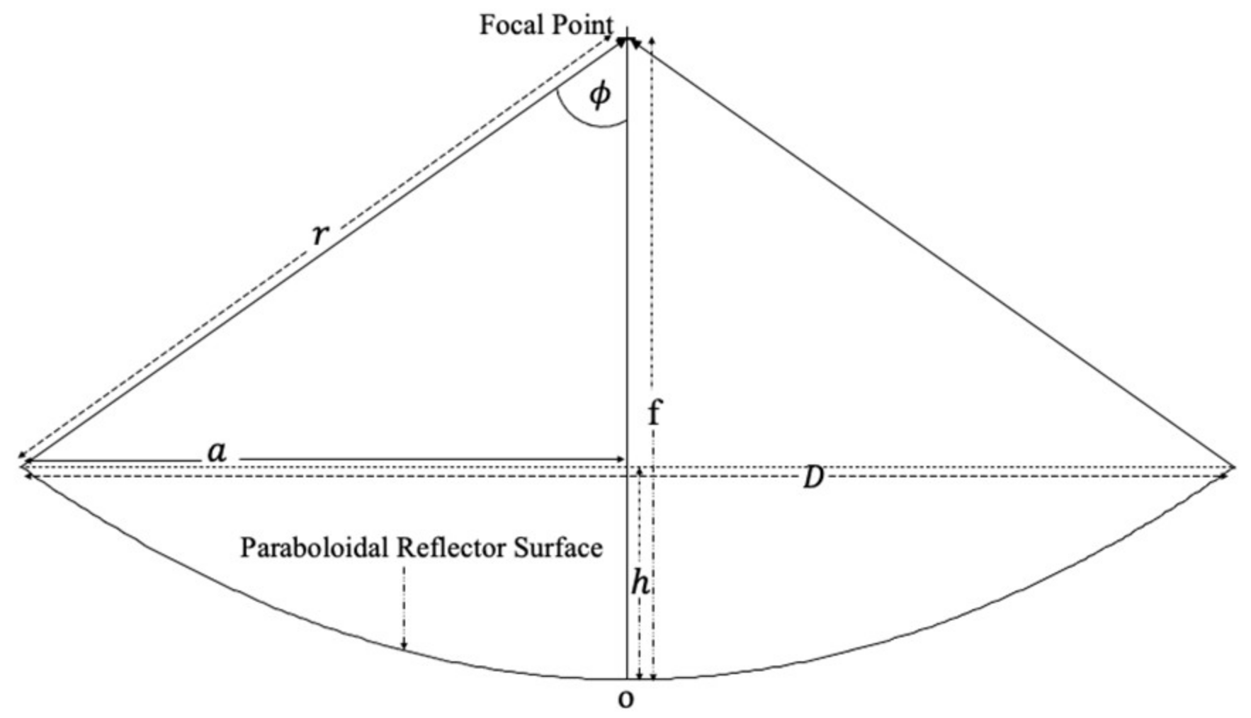
Figure 1. Design parameters of a solar paraboloidal dish concentrator.
Energies 15 07868 g001
Figure 2. Details of dish components.
Energies 15 07868 g002
Figure 3. (a): Azimuthal tracking. (b): LDR arrangement. (c): Elevation tracking. (d): Tracking circuit.
Energies 15 07868 g003
Figure 4. Thermal profiles of different heat transfer fluids (EO 15 November, EG 17 November, SO 20 November, and Water 23 November 2021) of capacity 0.5 L each in dish concentrator receiver (Tb and Tf are receiver base and average fluid temperature, respectively).
Energies 15 07868 g004
Figure 5. Variation of solar insolation (Is) and ambient temperature (Ta) with Indian standard time (IST) on experimental days, EO 15 November, EG 17 November, SO 20 November and Water 23 November 2021.
Energies 15 07868 g005
Figure 6. Heating curves of HTFs in transient state (EO 15 November, EG 17 November, SO 20 November and water 23 November 2021).
Energies 15 07868 g006
Figure 7. Cooling curves of HTFs (EO 15 November, EG 17 November, SO 20 November and water 23 November 2021).
Energies 15 07868 g007
Figure 8. Variation of solar insulations (IS) and average fluid temperatures (Tf) with Indian standard time (IST) for SO of capacity 0.5 L (20 November 2021) and 0.5 L (09 November 2021).
Energies 15 07868 g008
Table 1. Review on different HTFs and their solar application.
ReferenceFluidSolar ApplianceApplicationTemperature (°C)
Boerema et al. [2]Hitec and Liquid sodium (Na)CSPHTF585/873
Trabelsi et al. [10]Therminol VPI and Molten SaltCSP TES400/593
Kenda et al. [11]Jatropha curcas crude oil CSPHTF/TES210
Hoffman et al. [12]Seven vegetable oils CSPHTFupto 250
Nkwetta et al. [13]Dow-corning 550 silicon oil ETC (non-concentrating) HTF67
Jung et al. [14]Silicone fluid (HELISOL® 5)CSPHTF450
Peng et al. [15]Molten saltProperty study 550
Qoaidera et al. [16]Mobiltherm 603CSPHTF300
Perez-Tavernier et al. [17]Propylene glycol:water mixture (30:70% mass ratio)ETC (non-concentrating)HTFLow temp. 50
Jadhav and Venkatraj [18]Liquid Sodium, Hitec XL and SteamCSPHTF600, 873
Table 2. Design parameters of small size solar concentrator.
Ref.Dish DimensionsReceiver DetailsThermal Parameters
Dia.
(m)
Focal
(m)
Height
(m)
MaterialShapeDia. (m)FluidEfficiency (%)Max. Temp. (°C)
Ouederni
et al. [19]
2.20.750.4SS & copperDish0.12No27375
Mohammed [20]1.670.580.30AluminiumCylinderical0.14Water50100
Omara and
Eltawil [21]
1.00.400.20---Brackish water34101
Subramani et al. [22]1.50.740.19CopperConical cavity0.008Water7797
Hassan
et al. [23]
1.01.02-CopperCylindr-ical & Conical 0.17Water59–6280
Mahavar et al. [24]1.210.450.20CopperCylindr-ical Water with charcoal-80
Kumar & Yadav [25]1.830.784-Anodized Aluminium Sheet0.15No 309
Table 3. Properties of heat transfer fluids [5,6,14,27,28,29,30,31].
PropertiesWaterSilicone OilEngine OilTherminol 66Ethylene Glycol
Density (kg/m3 at 25 °C)100090087010081113
Flash point (°C)-315238184126
Auto ignition Temperature (°C)-450>234374427
Boiling point (°C)100>250>176359197
Critical temperature (°C)374-434569446
Kinematic Viscosity, cSt (100 °C)0.293810–100012.5–163.771.99
Thermal Conductivity (20 °C) (mW/K)0.60.100.130.120.25
Specific Heat (50 °C) (kJ/kg°C)4.1861.72.12.12.4
Toxicity No Low HighlyLowHighly
Environmental HazardsFriendlyModerateHighModerateHigh
Approximate cost INR (per liter)308002003000400
Table 4. Instant thermal efficiency of HTFs.
Time (min)Heat Transfer Materials
q a   ( W ) q u ( W ) η i t h   ( % )
WEGEOSOWEGEOSOWEGEOSO
038937440336816010314515941313643
5392385404370130829112033272332
10396398405374105599110827212329
153884034103699553596425151417
203954014163705164494713131213
254034044203862010293956710
Table 5. HTF heating and cooling characteristics.
HTFHeating CurveCooling Curve
Transient StateSteady StateRc vs. (TfTa) Curve
RgRh (°C/s) Max .   η i t h     ( % ) T f m ¯ ( ° C ) I s ¯   ( W / m 2 ) Tnf
(°C)
Rg τ c ( min ) U L ( W / mK )
Water0.993.21411015881200.961726
EG0.983.95311615711980.961123
EO0.984.66361736032000.981515
SO0.986.56452235762740.971414
Publisher’s Note: MDPI stays neutral with regard to jurisdictional claims in published maps and institutional affiliations.