Abstract
DC-DC power converters play an important role in the performance and control methods of solar power systems. Solar power converters are prone to high power losses due to intermittent irradiation and shading effects on solar photovoltaic (PV) modules. The device topology and control algorithm of a solar power converter are key factors to increase the total amount of harvested energy. In this paper, a solar power converter is proposed with a two−phase interleaved boost converter (IBC) topology and a novel maximum power point tracking (MPPT) method. The proposed MPPT controller is based on extended Kalman filtering (EKF) and it improves the tracking efficiency in both steady irradiation and partial shading conditions. The algorithm is improved with the prediction and estimation capabilities of the EKF algorithm. The proposed EKF MPPT is validated with simulations and experimentally validated by using the implemented two−phase IBC that is comprised of SiC MOSFETs. The proposed converter provides over 99% power conversion efficiency at 3 kW and over 96% MPPT tracking efficiency under partial shading conditions. The experimental studies verify that the proposed MPPT controller and two−phase IBC increase the overall efficiency both in steady-state and partial shading operations of a solar power converter.
1. Introduction
Global warming and the widespread use of fossil fuels are widely acknowledged to be the most significant threats to recent environmental issues. Renewable energy sources (RES) are being extensively researched in terms of efficiency, capacity, and reliability aspects in electricity generation to reduce the harmful effects of fossil fuels. The generation capacity of any RES is obviously dependent on climate conditions and may be intermittent due to its nature [1,2]. It is widely reported that the use of RES is tremendously increasing due to a wide variety of alternative sources [3,4,5]. While the decreasing reserves and increasing costs of fossil fuels were forcing governments to search for alternative sources, recent conflicts have leveraged these motivations for the increased use of RES for responding to the energy demand. Despite the availability of various ratios, governments initially allowed only a maximum of 30% RES penetration to the utility grid. The increased production costs triggered a greater sense of optimism driving the conversation for 100% RES use in electricity generation by 2050 [5]. According to the Renewables Global Status Report 2020, solar photovoltaic (PV) plants hold the third major share with 627 GW global capacity after hydropower and wind power systems. Additionally, solar PV was the leading RES with 200 GW capacity added in 2019 [6].
PV power systems have gained increased attention in recent years as a viable solution to RES applications due to their modular structure, long PV module lifetime, and low maintenance requirements when compared to wind turbines or hydropower systems. However, depending on temperature and irradiance, the output voltage and rated power of a PV module can easily change. A solar power plant’s combined efficiency is determined by the performance of its PV modules, power converters, and power controllers using the maximum power point tracking (MPPT) algorithm. Due to the limited efficiency of PV modules, researchers are working to improve extremely efficient power converters and control algorithms in order to operate solar power plants with the highest possible efficiency. As a result, power converters and controllers should strive to achieve near-unity efficiency rates [7,8].
DC-DC converters are the primary power electronic devices used in solar power plants, and the MPPT algorithm ensures reliable and stable operation even at low potential. The second stage must be fitted with inverters if AC loads need to be supplied or the plant needs to be connected to the utility grid. The DC-DC converters that connect the PV modules are designed to boost the low input voltage in order to generate a common dc bus, and they ensure that the DC bus may be used reliably as the supply of the second stage, which comprises the inverter section, or to be used with a DC source. The disadvantages of conventional converters include rapid changes in input voltage and current, high switching losses, and reverse currents of diodes. As a result, the efficiency of the DC-DC converter is reduced more than expected in conventional topologies built with silicon (Si) devices [9]. The proper converter topology ensures an efficient PV system with reduced power loss, increased power harvesting, and dependable MPPT operation. According to the configurations, the most common PV applications are classified as standalone, on-grid, and hybrid [10]. The control methods, device topologies, and overall efficiency of DC-DC converters are being extensively studied in discontinuous conduction mode (DCM) and continuous conduction mode (CCM) operations [7,10,11,12]. The RES applications, including PV systems, are defined as converter-interfaced sources similar to electric vehicle (EV) and energy storage system (ESS) applications [12]. To overcome the drawbacks of conventional non-isolated topologies such as boost and buck-boost, single-ended primary-inductor converter (SEPIC), flyback, and interleaved-based converter topologies are widely researched and improved. Interleaved and soft-switching converters are popular due to their dependable operation with advanced controllers and low power losses. While soft-switching converters require more reactive elements and more complex control methods, the interleaved boost topology delivers a higher power conversion ratio with fewer devices. A two−phase interleaved boost converter (IBC) is controlled by switching signals that are 180° out of phase with one another and switching power losses are decreased since the current is generated by two branches. Aside from power sharing, the two−phase IBC improves overall efficiency and power rate. The output capacitors of each phase double the ripple frequency and eliminate ripple voltages much more effectively [2,13,14,15].
In addition to the converter topologies, the power semiconductors used in the converters are being extensively researched in order to improve efficiency and reduce power losses, which are key objectives in the design of power converters. Si MOSFETs and Insulated-gate Bipolar Transistors (IGBTs) have been used for many years in power converters. However, wide bandgap devices such as silicon carbide (SiC) and gallium nitride (GaN) are gaining popularity due to their advantages in overcoming the high loss, low switching frequency, high leakage current, and high-temperature issues of Si devices [16,17]. Although the high cost of wide bandgap devices has limited their widespread usage, the advantages of SiC and GaN devices such as greater blocking voltage, higher switching frequency, and lower switching losses have increased their utilization. The technical structure of these semiconductors not only improves system performance but also increases power density in the conducted design. Many hybrid topologies built with SiC and Si devices are proposed in the literature to reduce overall costs and increase system efficiency [18,19,20]. Ding et al. proposed a microgrid-connected inverter made of SiC MOSFETs and Si Insulated-gate Bipolar Transistors (IGBTs) in [18], and Feng et al. improved a three-level active neutral point clamped (ANPC) inverter in [20]. Both studies found that by replacing some Si devices with SiC, the overall efficiency of converters was significantly increased. According to the literature review, SiC devices are still not widely used in power converters.
In addition to replacing switching devices, improving the controller algorithm of the power converter is another option for increasing the overall efficiency of a solar converter. The main contribution of the MPPT controller to solar converters is its ability to detect and track the maximum power rate of the solar modules. Even though the goal of an MPPT controller is to drive switching devices at optimal conditions and maximize overall efficiency, it must be able to rapidly react to voltage and current fluctuations. In addition to variations on the source side, load fluctuations influence the performance of the MPPT controller. Many different types of MPPT controllers have been proposed in the literature for use in RES converter interfacing applications [7,21,22,23,24,25,26]. MPPT controllers are classified into three types: direct, indirect, and computational methods. Due to their faster detection and response to fluctuations, the perturb and observe (P&O) and incremental conductance (InCon) methods are the most widely used in commercial converters. However, these MPPT algorithms are mostly used in open-loop mode, with feed-forward processing that ignores the voltage reference. The sensitivity of voltage and current sensors determines the efficiency of the control algorithm in this type of operation. Many computational methods have been proposed to address the inefficiency issues with direct MPPT controllers [23,27,28]. Fuzzy logic controllers (FLC), artificial neural networks (ANN), particle swarm optimization (PSO), and genetic algorithm-based MPPT algorithms are also proposed as alternatives to conventional controllers. Even though all of these computational and meta-heuristic algorithm-based MPPT methods aim to overcome the drawbacks of P&O and InCon, the computational processes cause slow tracking responses and increased complexity for the controller. Furthermore, when computational algorithms are run on low-performance processors, their performance suffers dramatically [23]. In addition to the complexity of MPPT controllers, insufficient performance in global maximum power point (GMPP) tracking under partial shading is another disadvantage of direct and indirect MPPT controllers. Partial shading causes changes in the magnitude and polarity of shaded cells in a PV module, and it prevents the module from operating at MPP due to distorted voltage characteristics. The MPPT algorithm’s main goal is to precisely track and detect the GMPP under partial shading conditions against different local MPPs [29]. The optimization and bio-inspired algorithms are designed to outperform conventional methods in GMPP operation. In this study, the extended Kalman filter (EKF) is investigated rather than widely proposed computational MPPT methods. It aims to improve a robust, fast-reacting, and simple MPPT controller for solar systems that prioritizes GMPP operation. Even though the Kalman filter is widely used in motor drives and electrical machine control due to its accurate operation at parameter estimations, it is an important method that can be used for state or parameter estimation in any engineering problem. The EKF can overcome disturbances in the controlled plant by employing the controlled system’s discrete nonlinear model. According to the literature review, EKF-based MPPT applications are proposed to control wind turbines and ESSs based on generator or battery parameter estimations, respectively. These applications demonstrated that EKF-based MPPT outperforms other MPPT methods used in wind turbines and ESS control [14,25,30,31,32]. On the other hand, it is worth noting that there are only a few simulation studies that propose the EKF-based MPPT controller for PV applications in the literature [33,34]. As a result, the goal of this study is to improve an EKF-based MPPT controller to fill the gap and investigate the performance of a better controller to overcome the problems encountered in local and global MPPT operations.
The proposal of this study includes the improvement of two aspects of a solar power converter. The first contribution is an improved converter topology in a two−phase interleaved boost converter (IBC) configuration that uses SiC MOSFETs to overcome switching losses and improve overall efficiency at the hardware stage. The driver, power conditioner, and data acquisition components are all designed to meet the accurate measurement and rapid drive requirements of the power converter. The second contribution of this study is the proposed MPPT controller, which is based on an EKF method that ensures rapid GMPP tracking. In addition to maximum power tracking capability, the proposed EKF MPPT controller is enhanced to operate in closed-loop control with a voltage tracking feature. Thus, not only is faster tracking obtained but also a stable dc bus voltage level is ensured thanks to the proposed EKF MPPT controller. The novelties and contributions of the proposed study are summarized as given below:
- A highly efficient and high-gain IBC is improved with SiC semiconductors to be used in solar power systems;
- An EKF-based MPPT method has been proposed to overcome the slow tracking capability and low efficiency of conventional MPPT algorithms in partial shading operations;
- The proposed algorithm has been improved to operate with and without voltage reference to maximize tracking efficiency;
- The efficiency of the proposed SiC IBC converter and performance of the proposed EKF MPPT controller are verified with simulation models and experimental validations are performed under regular and partial shading operations.
The methodology of EKF MPPT has been introduced in detail in the following sections. The comparisons are made through simulation and experimental studies and the increased tracking efficiency is verified with various test conditions including partial shading. Section 2 describes the mathematical modeling and device structure of the proposed two−phase IBC while the improved EKF MPPT is introduced in detail in Section 3. Section 4 and Section 5 present the simulation and experimental studies, respectively. Section 6 encloses the discussion comments, while Section 7 draws conclusions and recommendations.
2. Modelling Two−phase IBC and Operational Principle
A two−phase IBC topology is used in the proposed solar DC-DC converter. The primary function of a boost converter is to increase the input voltage to a higher level at the output. The proposed interleaved configuration adds benefits such as lowering ripple currents on the input and output sides of the converter and increasing overall efficiency by splitting the output current into two paths. This is accomplished primarily by lowering copper and conduction losses. Figure 1 depicts the implemented IBC, including controller block diagrams and a snubber structure. When the S1 switch is turned on, the current flows over the L1 inductor, and the energy is stored in the first phase inductor in the presented two−phase interleaved topology. When the S1 switch is depressed, the sum of the inductor and source voltages is applied to the output capacitor and the load across the D1 diode. S1 is turned off and S2 is turned on during the next switching period, which is complementary to the first half-cycle. In this cycle, all the processes described in the first part are repeated in the second phase of the converter. Thus, the energy is stored in the L2 inductor and then transferred to the load via the D2 diode during the turn-off cycle of the S2 switch. Because both boosting paths are coupled at the output capacitor in this design, the ripple frequency is double that of the single boost converter. A single-channel boost design and shunt connected with identical inductor and diode parameters are used to determine the system components. Switching device gate signals have a 180° phase difference from one another, which is determined by 360/n, where n is the phase number [35].
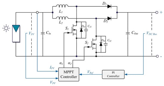
Figure 1.
Proposed two−phase IBC and block diagram of MPPT controller.
The theoretical waveforms of a two−phase IBC are illustrated in Figure 2 where the operation modes and outputs are determined regarding the duty cycle (d) rate. The circuit can be operated in four modes referring to the switching positions of S1 and S2 devices.
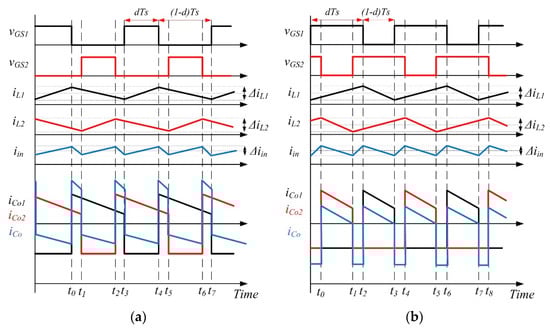
Figure 2.
Waveforms of two−phase interleaved boost converter: (a) d ≤ 0.5; (b) d > 0.5.
The IBC benefits from ripple cancellation and reduced input current ripple in both duty cycle operation modes, as shown in Figure 2a. The ripple rate of the output capacitor current becomes zero in this case. The rising slope of the input current in the d < 0.5 switching condition is equal to the rising time of any of the L1 and L2 inductors at dTs duration. The ripple rate of input current ΔIin is calculated as the difference between the rising and falling edges of the inductor currents, as shown in (1), whereas the peak-to-peak input current ΔIin is given in (2):
If we recall the output voltage equation of the boost converter in (3) and substitute Vin from (2), the input current ripple for d < 0.5 is obtained as in (4):
When the duty cycle exceeds 0.5 (d > 0.5) as seen in Figure 2b, the time of rising slope at the input current is calculated as in Equation (6) and the input current is obtained as in Equation (7):
Aside from the duty cycle being either greater than or less than 0.5, the IBC control operation is primarily based on phase-shifted switching of S1 and S2 semiconductors to eliminate input current ripples [36,37,38]. The normalized ripple ratio of input current k(d) which is a function of d is depicted as in Equation (8):
The operation principles and waveforms of IBC presented above show that the ripple current of the converter is improved compared to conventional topologies. The interleaved inductors that are identical and shown as L1 and L2 in Figure 1 share the input current, and the energy is equally stored in these interleaved inductors. The total energy stored in the inductors is shown in Equation (10) [37]:
where Iin is the input current and half of that is in a conventional boost converter.
The two−phase interleaved boost converter operates in four modes, which are depicted in Figure 3 and defined below. The state-space averaging method is used to analyze the operation modes of two−phase IBC in terms of the switching orders depicted in Figure 3 and operational equivalent electrical circuits depicted in Figure 4. Inductor currents (IL1, IL2) and output voltage are used to define the state variables (VO) [13,35,38,39]. The operation modes and state-space equations are described below:
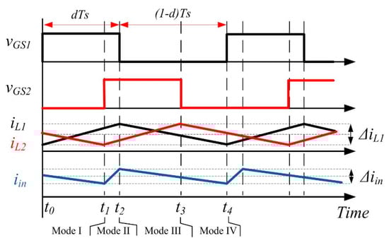
Figure 3.
Waveforms of two−phase IBC in operation modes (d ≤ 0.5).
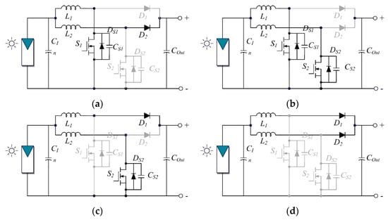
Figure 4.
Operation modes of two−phase IBC: (a) Mode I; (b) Mode II; (c) Mode III; (d) Mode IV.
Mode-I [t0 ≤ t < t1]: Figure 4a shows the equivalent circuit for this operation mode with S1 turned on and S2 turned off. In this switching interval, the current of inductor L1 (IL1) is increased, and the inductor stores the energy. As IL1 increases, the diode on the inductor path becomes reverse-biased, and the load is supplied by the energy stored in inductor L2, resulting in a decrease in IL2 current. The state-space model of this operation mode is inherited, as shown in Equation (11):
Mode-II [t1 ≤ t < t2]: Figure 4b depicts the equivalent circuit for this operation mode, in which both switching devices are turned on and both diodes are reverse-biased. In this mode, inductors share the input current, and L1 and L2 store energy. As a result, the voltages of the inductors become equal. Equation (12) depicts the Mode-II state-space model.
Mode-III [t2 ≤ t < t3]: This mode of operation can be thought of as complementary to Mode-I, as illustrated by the equivalent circuit in Figure 4c. S1 is turned off and S2 is turned on, and the current of inductor L1 (IL1) is reduced because the load is fed through the L1-D1 path. When the diode D2 is reverse-biased, the amount of energy stored in the inductor L2 increases. The state-space model of Mode-III is given in Equation (13):
Mode-IV [t3 ≤ t < t4]: Figure 4d depicts the equivalent circuit diagram for this operation mode. Both S1 and S2 are turned off in this mode, and diodes are forward-biased. In state-space models, the currents of L1 and L2 decrease, and the stored energy in inductors is fed to the load, which is represented as RL. The state-space model of Mode IV is obtained as follows:
The critical values of inductors L1 and L2 that are required to maintain continuous conduction mode (CCM) operation are determined by using Equation (15) while the minimum COut is obtained with Equation (16):
where TS is the switching time, and VRP is the allowed ripple voltage at the output [35].
The voltage conversion ratio M of two−phase IBC is derived as seen in Equation (17) [40];
3. The EKF-Based MPPT Algorithm
The generation characteristic of a PV module is highly dependent on irradiance and temperature values. The proposed MPPT algorithm is improved with EKF in this study, and the output voltage is fed back to the MPPT algorithm to track both the input and output conditions of the solar converter. To extract recursive solutions, the Kalman filter is composed of mathematical equation sets based on the least-square method. According to Kalman’s article describing the filtering method, there are two sets of equations: the time update and the prediction state [41,42]. Both sets are used to comprise the prediction and correction steps of the filtering process, and the weighted average is calculated using the error covariance in the Kalman filter [30]. The Kalman filter, which is required to understand the proposed MPPT method, is summarized in Equations (18) and (19), where a discrete-time dynamic system is presented with a state-space model of system state and measurement data [9,42]:
where k represents the interval while the k + 1 is the next interval, x(k) is the state vector of n × 1 system at k interval, u(k) is the n × n time-varying state transition matrix, z(k) is an m × 1 measurement vector representing the output signals, Cx(k) is m × n time-varying measurement transition matrix, ω(k) is n × 1 system state noise error and v(k) is measurement noise error of an m × 1 system matrix. It needs to be expressed that the noise vectors ω(k) and v(k) are independent zero-mean normal noises as denoted in Equation (20) and covariance in Equation (21):
where Q and R represent the positive semi-definite and positive definite matrices, respectively. The two−step process of Kalman filtering can be performed as an iteration of measurement update and prediction update for any system if the problem is described in the state-space model. Thus, Kalman filtering can be carried out for making predictions at the next state and observation vector x(k + 1) and z(k + 1) as depicted in Equations (18) and (19). EKF represents an approximation for the optimal estimation of the system. A linearized model of the non-linear system around the last state estimate approximates the non-linear parameters. If we assume that a set of a nonlinear system is described by a deterministic difference equation, it is denoted with the state vector of xk−1 and nonlinear vector function of f(xk−1) that defines the dynamics of the system as seen in Equation (22):
The outputs of the system are described as depicted in Equation (23):
where h(xk) represents the state vector and random sequence vk corresponds to the system noise. The noise is distributed with (0, Rk) where Rk is the covariance matrix of vk that is used for tuning the EKF. The state vector given in Equation (22) is estimated by EKF considering the subjecting noise parameter:
In this expression, ωk represents the uncertainties of noise with (0, Qk) where Qk is the covariance matrix of ωk. The optimal estimation of xk is dependent on the outputs of yk and the inherited data from Equation (24). The improved study is based on Equation (22) and the resulting state estimation, prediction matrix of estimation error, EKF filter gain, and updated estimation matrices are given in the following equations:
The superscripts of p and u indicate the prediction and update phases in the given expressions. The parameters denote the estimation of state xk given in Equation (22) while Equation (26) represents the predicted covariance matrix of the estimation error. Equation (27) describes the EKF gain with Kk, and Equation (28) denotes the local optimal estimation of xk with . The updated covariance matrix of the estimation error Pku is given in Equation (29) where Rk is the covariance matrix of vk while Pku and Pkp are symmetric and positive definite matrices. The matrices of Ak−1 and Ck denoted in Equations (30) and (31) are inherited by using Taylor’s linear approximations regarding nominal values of , and vk = 0.
The approximations are revised for those given in Equations (22) and (23) and are derived as seen in Equations (32) and (33):
The EKF estimator presented here is derived from conventional Kalman filters described in the literature [43,44,45,46]. Although numerous EKF applications for controlling electrical machines and wind turbines have been proposed, very few studies based on EKF MPPT for controlling conventional boost converters have been presented [33,34,47]. The EKF MPPT controller for two−phase IBC has been improved considering the state-space model of the converter presented in the second section. The discrete-time dynamic system shown in Equations (18) and (19) is used in conjunction with the state-space average model of system state and measurement data shown below:
The operation modes of two−phase IBC given from Equation (11) to Equation (14) are recalled deriving a state-space model to implement EKF MPPT. The coefficient matrices of the converter are obtained as denoted in Equation (37) referring to switching intervals shown in Figure 5 and the following expressions:
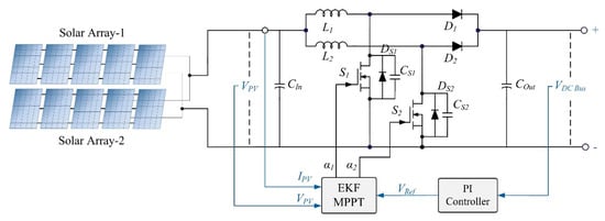
Figure 5.
Schematic diagram of the simulation model for two−phase IBC with EKF MPPT controller.
Thus, the state-space equations are obtained by combining four operation modes as follows:
The EKF controller can be expressed by using the discrete model of two−phase IBC as follows:
where K(k) is the Kalman gain, and are estimated parameters, Ad is I + ATs, Bd is BTs, Cd = C and Dd = D. In the first step, the implemented EKF algorithm is initialized with state vectors and covariance matrices. Following that, the state vector prediction (Equation (32)) is performed. In the third step, Equation 26 is used to predict the matrix of error covariance, and Equation 27 is used to calculate the Kalman gain. After making predictions in the first three steps, the update cycle begins in the fourth step, where Equation 28 is used to update the predictions through measurements. The error covariance matrix is then updated using the process described in Equation 29, and the algorithm is returned to the second step, where state vector prediction is restarted. It should be noted that the expressions given in Equations (30) and (31) perform the summarized steps of Equations (25)–(29) and (43).
4. Simulation Analyses and Results
The simulation infrastructure of the proposed EKF MPPT controller and two−phase IBC is improved with Matlab/Simulink in relation to the design parameters given in the second and third sections. The solar plant was designed with two parallel PV arrays, each with five modules connected in series. Figure 5 depicts the schematic diagram of the solar plant and IBC, while Table 1 lists the system parameters. The solar array model shown in the figure is set up to generate 2500 Wp of power for the two−phase IBC feeding a resistive load of 50 Ω. The IBC circuit parameters are listed on the right half of Table 1, where fast recovery diodes (FREDs) are modeled using the datasheet of DSEI 60-12A [48] and SiC MOSFETs are configured using the parameters of ON Semiconductor’s NVHL080N120SC1 with an RDS(on) value of 80 mΩ RDS(on) [49]. In simulation studies, the switching frequency generated by the MPPT controller is set to 100 kHz. The simulation studies are performed under steady and dynamic weather conditions by changing irradiation values at five regions, as shown in Figure 6, to validate the proposed EKF MPPT.

Table 1.
PV Module and Circuit Parameters.
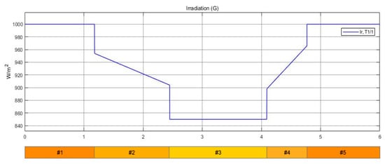
Figure 6.
Irradiation conditions applied to test the MPPT controller.
Three stable irradiation values are used in the MPPT algorithm performance analyses: 1000 W/m2, 850 W/m2, and 1000 W/m2 at the first, third, and fifth regions. As shown in Figure 6, the PV array is subjected to dynamic irradiation values that decrease from 950 W/m2 to 905 W/m2 in the second region and increase from 900 W/m2 to 965 W/m2 in the fourth test region. Figure 7 and Figure 8 show the voltage and current variations of the PV array and the load side of the IBC, respectively.
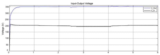
Figure 7.
Input and output voltages of two−phase IBC with EKF MPPT.
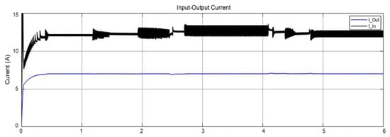
Figure 8.
Input and output currents of two−phase IBC with EKF MPPT.
The PI trigger of MPPT sets the output voltage of IBC (shown in blue in Figure 7) to 350 V to generate a fixed dc-bus level. It is also possible to adjust the dc voltage level to meet specific needs. The results of the analyses show that the dynamic change in irradiation values shown in Figure 6 has little effect on the output voltage. Furthermore, the decreases seen at the start of region #3 or the increments seen at the start of region #4 are only a few volts. In addition to voltage stability, the load current is measured as stable in comparison to the fluctuating input current supplied by PV modules, as shown in Figure 8. As shown in Figure 8, the EKF-based MPPT algorithm eliminates load current ripples and produces a stable waveform. By compensating for deviations, the PI-controlled output voltage set to a reference value allows the converter to operate at constant voltage and constant current profiles.
Figure 9 depicts the maximum power transfer analyses, with the input and output power curves represented by blue and black lines, respectively. In terms of the PV modules used in the design, the PV power plant was designed to generate 2500 Wp of solar power. The power analyses presented for the entire simulation time and a zoomed view of the selected part show that at maximum irradiation values, the generated solar power fluctuates between 2465 W and 2500 W. The lowest output power measured in this analysis indicates that the power conversion ratio of the solar plant is 98.6% in the worst case. On the other hand, the output power of the IBC, which is nearly 20 W lower than the power of the solar plant, confirms that the MPPT tracking efficiency is greater than 99%. As shown in Figure 9, the MPPT algorithm detects changes in input power immediately and forces IBC to transfer the maximum available power to the output to ensure tracking efficiency.
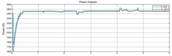
Figure 9.
Input and output power curves of two−phase IBC.
Figure 10 depicts a detailed analysis of IBC efficiency. The spikes represent the areas in Figure 6 where the irradiation is reduced or increased. The overall efficiency of the EKF MPPT algorithm is around 99.4% while changing irradiation causes 1% fluctuations that are not taken into account due to transient states. Region #4, which causes significant deviations in power and voltage values, is magnified in the efficiency analysis. The measured results confirm that the steady state efficiency in the other regions is around 99.4%.
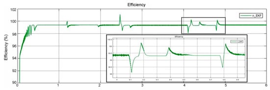
Figure 10.
Efficiency analysis of two−phase IBC.
Modeling studies have aided in the improvement of EKF-based MPPT algorithms in terms of determining the best Kalman filtering prediction and estimation cycles. Optimizations were performed based on recent measurements and analyses, and the best results presented here were assumed adequate to be tested in the experimental system.
5. Experimental Studies
The two−phase IBC experimental setup is constructed using the equivalent values of the simulation model shown in Table 1. Table 2 lists the circuit parameters used in the optimal design of the experimental device, with slight differences in capacitor values and switching frequency compared to the simulation model. Chroma Solar Array Simulator (SAS) 62050H-600S model programmable source is used in the solar plant models. The experimental test studies were conducted in accordance with the scenarios presented in the simulation section, and all conditions were rigorously applied in the testbed.
Table 2.
Experimental Circuit Parameters.
To validate the MPPT tracking capability of the proposed EKF-based control algorithm, steady irradiation and partial shading conditions of solar plant models were analyzed. Figure 11 depicts the implemented two−phase IBC with SAS and loads. The IBC power block is built in a modular structure, with the SiC MOSFETs and FREDs mounted on the heatsink at the bottom layer, as shown in the figure. The PCB layer of heatsink houses PV plant inlets, input electromagnetic interference (EMI) filters, input-output capacitors, MOSFET drivers in dock structure, and isolated current and voltage measurement boards, which are also mounted in modular docks.
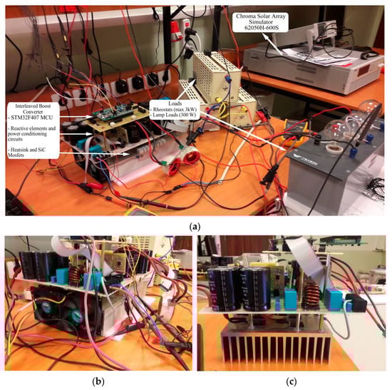
Figure 11.
Experimental test setup of two−phase IBC: (a) solar array simulator, IBC and loads; (b,c) side views of IBC power block.
Figure 11a depicts the implemented two−phase IBC with SAS and loads. The IBC power block is built in a modular structure, with the SiC MOSFETs and FREDs mounted on the heatsink at the bottom layer, as shown in the figure. Figure 11b,c show side views of the IBC power block, which provide a better view of the components of power conditioning circuits and other components. Because of the output voltage and current ratings, the power converter components allow the two−phase IBC to operate at up to 3.5 kW.
The proposed EKF MPPT, which is enhanced with a PI feedback controller, was used to control the implemented hardware. Figure 12a shows a sample measurement result where the switching frequency is set to 32 kHz and the input voltage generated by the SAS solar plant model fluctuates between 220 V and 280 V. The output voltage is set to 360 V, as shown by the pink line in Figure 12b. As seen in the red line, the gate-source switching signal applied to SiC MOSFETs is also analyzed. A robustly configured snubber circuit of SiC MOSFETs eliminated the ringing factor, and the removal of on-off ringing ensured reliable operation. The implemented two−phase IBC has been validated experimentally with various solar plant models, with the converter operating at 1 kW, 2 kW, and 3 kW loads. As shown in Figure 13, Figure 14 and Figure 15, all of the solar plants were designed to operate with partial shading and constant irradiation. The solar plant model was built in the first test system with three parallel arrays of five series PV modules at each array, as shown in Figure 13. The total maximum power voltage (VMP) is set to 247.9 V, and the maximum power current (IMP) is 3.83 A, with partial shading conditions applied to the lower three modules.
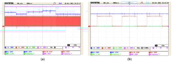
Figure 12.
EKF MPPT control of two−phase IBC: (a) input voltage (blue line), output voltage (pink line), G-S switching signal (red line); (b) zoomed views.
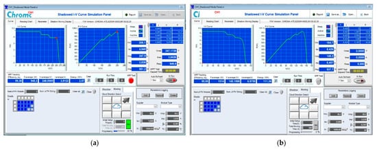
Figure 13.
EKF MPPT test of two−phase IBC with 1 kW load: (a) partial shading and global MPPT tracking; (b) overall MPPT tracking efficiency.
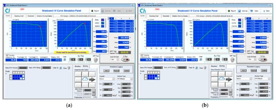
Figure 14.
EKF MPPT test of two−phase IBC with 2 kW load: (a) partial shading and global MPPT tracking; (b) overall MPPT tracking efficiency.
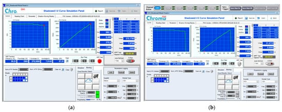
Figure 15.
EKF MPPT test of two−phase IBC with 3 kW load: (a) partial shading and global MPPT tracking; (b) overall MPPT tracking efficiency.
Figure 13a shows that the proposed EKF MPPT algorithm can detect GMPP under partial shading operation. Under these operating conditions, tracking efficiency is 99.38%. The proposed EKF MPPT’s overall MPPT tracking efficiency was measured at 95.95%, as shown in Figure 13b, where the average power was 1014 W and all GMPP were successfully tracked by the algorithm.
The implemented converter was then analyzed by increasing the solar plant power to 2 kW and loading it with resistive and lamp loads at 2 kW. As shown in Figure 14a, the VMP of the solar plant model has been set to 280.1 V and the Imp to 7.236 A. The solar plant was built with two parallel arrays of five series PV modules each. The analyzed operation demonstrated that the MPPT algorithm could track the GMPP with an MPPT efficiency of 96.50%. The overall converter efficiency of the proposed MPPT algorithm was 98.37%, as shown in Figure 14b, with the average power delivered to the load being 1936 W at the end of the test period.
The maximum loading analysis of the proposed converter was performed by increasing the solar plant power to 3 kW, where the VMP of the solar plant model was 376.8 V and the IMP was 7.95 A, as shown in Figure 15a. This test procedure also used partial shading and constant irradiation conditions. The MPPT tracking efficiency was 99.51% at 2983 W load power, and the overall efficiency was 96.95%. The average power delivered to load has been calculated to be 2989 W, as shown in Figure 15b of the solar array simulator.
The measured power and efficiency rates are obtained from Chroma SAS’s precise measuring tool, which tracks the source power drawn from the solar plant and the load power delivered at the output of the solar converter. As a result, instant variations and overall efficiency values are precisely calculated in this manner.
The partial shading tests of the proposed EKF MPPT confirmed that the two−phase IBC could provide tracking efficiency of more than 96% at any load value up to 3 kW. In contrast, the power conversion efficiency of IBC was found to be 99.93% based on measurements obtained during the experimental analysis of the Chroma solar array simulator. The minimum total losses of the proposed power converter at rated power are measured as 2 W, as shown in Figure 15b, where the transferred average power was 2989 W versus 2991 W of solar plant maximum power.
The total power loss, which is composed of conduction loss, switching loss, dead-time loss, MOSFET gate charge loss, and operating losses, is compared between theoretical and real power loss calculations. The literature includes a substantial number of studies [50,51,52,53] that analyze MOSFET losses theoretically. The switching transitions shown in Figure 16 are used to determine the conductivity loss, where the A and B areas are taken into account. The high-side MOSFET is ON and the low-side MOSFET is OFF in Area A. Therefore, using the output current, on-resistance, and on-duty cycle, conduction loss may be estimated. The low-side MOSFET is ON in Area B while the high-side MOSFET is off. Therefore, the output current, on-resistance, and off-duty cycle may all be used to compute conduction loss. Equations (44) and (45) show the calculation method used for conduction losses PON-H and PON-L where IO denotes the output current, RON-H and RON-L are on-resistance of high and low side MOSFETs, respectively, VIN is the source voltage and VOUT is the output voltage [53]:
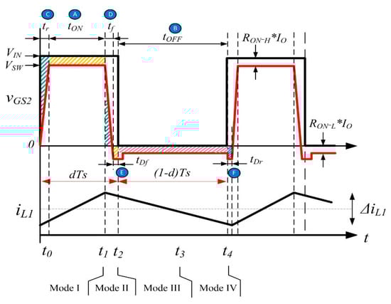
Figure 16.
Switching waveforms and power loss areas.
The conduction losses are also calculated with the following equation combining Equations (44) and (45) [51]:
The switching loss is determined considering the areas C and D in Figure 16. Switching loss is generated during the transition to ON when the high-side and low-side MOSFETs alternately turn ON/OFF. The calculation of switching loss can be estimated using a straightforward figure calculation because Equation (47) is used to compute the areas of the two triangles and is also used to calculate the power loss during the rise and fall transition. The parameters tr and tf are the rise and fall time of high-side MOSFETs, respectively, while fSW represents the switching frequency. During body-diode operation, the low-side MOSFET goes ON at the gate voltage. The load current then continues to flow in the same direction via the body diode after turning the MOSFET OFF at the gate voltage. As a result, the switching-loss PSW-L becomes minimum, and the drain voltage remains low.
The rise and fall time (tr and tf) of MOSFET are calculated as given in Equations (48) and (49):
where Q = QGS + QGD which are gate-to-source and gate-to-drain charge values.
The total power loss is determined as the cumulative result of Equations (46) and (47) as presented below:
Table 3 presents the parameters needed for the computations and the calculated losses using Equations (44) through (49) [49]. According to experimental research, the rise and fall periods of the NVHL080N120SC1 SiC MOSFET, which are listed in the datasheet as 13 ns and 22 ns in Table 3, were around 10 ns and 20 ns, respectively. In experimental tests, the maximum output voltage is set to 400 V while the rated input voltage is set to 250 V. According to the datasheet, the charge rates for gate-to-source (QGS) and gate-to-drain (QGD) are 11 nC and 12 nC, respectively. The gate currents at turn-on and turn-off transitions were measured as 1.77 A and 1.04 A.
Table 3.
MOSFET Parameters and calculated losses.
Each MOSFET in the IBC circuit has 1.30 W of conduction losses and 1.68 W of switching losses; for a total power loss of switching devices of 5.96 W. The experimental measurements of power losses shown in Figure 15 indicate that the overall power loss of the IBC converter is a maximum of 15 W at a rated power of 2998 W. The efficiency and power measuring modules of Chroma SAS, which is feeding the IBC, were used to obtain the experimental measurement results. The acquired results demonstrate that the experimental findings are closely in line with mathematical calculations
6. Discussions
The implemented solar power converter proposal deals with power converter design and proposes a novel MPPT controller based on the EKF method. Although interleaved converters have been described in the literature, the proposed DC-DC converter is enhanced with SiC MOSFETs to form the interleaved boost converter. In the literature, many similar converters improved with Si semiconductors have been proposed [13,54,55,56,57]. According to the literature review, almost all solar power converters were either validated with simulation studies or operated at low power rates. The authors improved the SiC MOSFET drivers and control board, and the proposed converter was experimentally tested up to 3 kW rated power in this study. On the other hand, the MPPT controller which is improved with the EKF method is another novelty of the proposed study. There are many MPPT methods available in the literature that are improved with FLC, PSO and with many bio-inspired search algorithms such as Cuckoo, firefly, artificial bee colony and so on [22,58,59,60,61]. Despite the fact that these MPPT methods locate the local maximum power point, the instantaneous variations or partial shading conditions cause significant power losses. Moreover, none of these methods take into account the state-space model of the converter and ignore the DC-DC converter parameters. The EKF-based MPPT method implemented in this study is proposed as an alternative to the novel soft-computing-based controllers. The proposed interleaved converter and EKF MPPT controller were experimentally validated, which has not been seen in the literature to the best of the authors’ knowledge. The obtained results confirm that the SiC MOSFETs increased the overall power efficiency of the converter, while the proposed MPPT controller ensured the highest MPPT tracking efficiency under partial shading conditions.
Table 4 compares the proposed converter to the studies presented in the literature, focusing on the most similar and closest studies. A recent review of the literature revealed that there are few studies using SiC IBC or EKF-based MPPT controllers. The power converter proposed in [57] is improved in push-pull topology with SiC device and rated power of 150 W. Although no information on the MPPT controller type is available, the tracking efficiency was stated to be 96% and the converter efficiency was stated to be around 86%. The EKF-based MPPT controller was only proposed in [47], which includes a simulation study with a boost converter rated at 200 W. The study provides no information on the efficiency of the power converter, and while the MPPT tracking efficiency is stated to be around 99.88%, it is unclear whether this was the instant efficiency or overall tracking efficiency. One of the most similar studies to the proposed one was found in [8], in which Jung et al. presented a soft-switching IBC controlled by a regular P&O MPPT algorithm. In [8], the authors proposed a converter design study with a rated power of 1200 W and stated that the overall efficiency of the power converter was 97.28% under full load operation.
Table 4.
Comparison of the proposed converter and MPPT controller with literature.
In [62], Koran et al. proposed a dual boost DC-DC converter with an 1800 W rated power that was experimentally tested with Chroma SAS. Although the MPPT control method was not explicitly addressed, and experimental results for a microinverter with a rated power of 150 W were presented in the paper, the MPPT tracking efficiency measured by SAS was stated to be 87%, while the overall efficiency of the converter acting as SAS was stated to be 96.7%. The study presented in [63] was carried out using a two−phase IBC based on SiC MOSFETs with a rated power of 2500 W. Despite the fact that this study’s hardware configuration and rated power are very similar to the proposed one, there is insufficient information about the MPPT controller. As a result, the MPPT tracking efficiency was not provided in the paper. According to the paper’s results, the converter design and control method was provided to achieve overall converter efficiency of around 99%.
A thorough literature review of the proposed study revealed that there are only a few papers that have low similarity to the one presented. The proposed two−phase IBC with an EKF-based MPPT controller uses SiC MOSFETs to increase the overall efficiency of the converter, while the EKF-based MPPT controller ensures robust tracking efficiency under constant irradiation and partial shading conditions to maximize the total harvested energy from the solar plant. Therefore, to the best of the authors’ knowledge, the proposed solar converter design presents a novel device and controller arrangement that have not been discussed in the literature.
7. Conclusions
This paper presents the complete design and implementation of an interleaved boost converter prototype using SiC MOSFETs and controlled by EKF MPPT, which has been experimentally validated. The contributions of the presented study can be summarized as twofold: the development of converter topology and the proposal of a novel MPPT algorithm based on extended Kalman filtering. The device topology and design criteria have been presented in detail and SiC MOSFET drivers and power controller circuits have been improved in the context of the presented studies. The experimental results show that SiC semiconductors contribute to lower switching losses and higher efficiency. The steady-state characteristics of the interleaved boost converter were investigated in order to implement the EKF-based MPPT to propose a novel MPPT controller which had not previously been used in solar converters. The laboratory prototype of the proposed converter has been implemented with 3 kW rated power for experimental verification, and the results demonstrated that the proposed MPPT controller increases the total power transferred to the loads. The overall efficiency of the IBC converter has been measured at around 99.3%. In comparison to existing algorithms, the proposed EKF MPPT provides simplicity, prediction robustness, and precise tracking efficiency even under partial shading conditions. It is worth noting that the proposed MPPT algorithm has a tracking efficiency of up to 96.5% when responding to abrupt changes or partial shading operations of solar plants.
Author Contributions
Conceptualization, E.K. and A.B.; methodology, E.K.; validation, E.K. and A.B.; investigation, E.K. and A.B.; resources, E.K.; writing—original draft preparation, E.K. and A.B.; writing—review and editing, E.K.; supervision, E.K.; project administration, E.K.; funding acquisition, E.K. All authors have read and agreed to the published version of the manuscript.
Funding
This research was funded by TUBITAK, grant number 7180822.
Acknowledgments
Authors acknowledge TUBITAK and Kaben R&D LLC for the funding and equipment support.
Conflicts of Interest
The authors declare no conflict of interest.
References
- Xu, L.; Wang, J.; Chen, Q. Kalman Filtering State of Charge Estimation for Battery Management System Based on a Stochastic Fuzzy Neural Network Battery Model. Energy Convers. Manag. 2012, 53, 33–39. [Google Scholar] [CrossRef]
- Sri Revathi, B.; Mahalingam, P.; Gonzalez-Longatt, F. Interleaved High Gain DC-DC Converter for Integrating Solar PV Source to DC Bus. Sol. Energy 2019, 188, 924–934. [Google Scholar] [CrossRef]
- Moriarty, P.; Honnery, D. Renewable Energy and Energy Reductions or Solar Geoengineering for Climate Change Mitigation? Energies 2022, 15, 7315. [Google Scholar] [CrossRef]
- Szeberényi, A.; Rokicki, T.; Papp-Váry, Á. Examining the Relationship between Renewable Energy and Environmental Awareness. Energies 2022, 15, 7082. [Google Scholar] [CrossRef]
- Bose, B.K. Power Electronics, Smart Grid, and Renewable Energy Systems. Proc. IEEE 2017, 105, 2011–2018. [Google Scholar] [CrossRef]
- REN21. Renewables 2020 Global Status Report; REN21 Secretariat: Paris, France, 2020. [Google Scholar]
- Kabalcı, E. Review on Novel Single-Phase Grid-Connected Solar Inverters: Circuits and Control Methods. Sol. Energy 2020, 198, 247–274. [Google Scholar] [CrossRef]
- Jung, D.-Y.; Ji, Y.-H.; Park, S.-H.; Jung, Y.-C.; Won, C.-Y. Interleaved Soft-Switching Boost Converter for Photovoltaic Power-Generation System. IEEE Trans. Power Electron. 2011, 26, 1137–1145. [Google Scholar] [CrossRef]
- Kumar, V.N.; Babu, P.N.; Kiranmayi, R.; Siano, P.; Panda, G. Improved Power Quality in a Solar PV Plant Integrated Utility Grid by Employing a Novel Adaptive Current Regulator. IEEE Syst. J. 2020, 14, 4308–4319. [Google Scholar] [CrossRef]
- Verbytskyi, I.; Lukianov, M.; Nassereddine, K.; Pakhaliuk, B.; Husev, O.; Strzelecki, R.M. Power Converter Solutions for Industrial PV Applications—A Review. Energies 2022, 15, 3295. [Google Scholar] [CrossRef]
- Di Nezio, G.; di Benedetto, M.; Lidozzi, A.; Solero, L. Analysis and Design of a High-Efficiency SiC MOSFET 6-Phase Boost Rectifier. Energies 2022, 15, 2175. [Google Scholar] [CrossRef]
- Lunardi, A.; Normandia Lourenço, L.F.; Munkhchuluun, E.; Meegahapola, L.; Sguarezi Filho, A.J. Grid-Connected Power Converters: An Overview of Control Strategies for Renewable Energy. Energies 2022, 15, 4151. [Google Scholar] [CrossRef]
- Banerjee, S.; Ghosh, A.; Rana, N. An Improved Interleaved Boost Converter With PSO-Based Optimal Type-III Controller. IEEE J. Emerg. Sel. Topics Power Electron. 2017, 5, 323–337. [Google Scholar] [CrossRef]
- Tan, B.; Li, H.; Zhao, D.; Liang, Z.; Ma, R.; Huangfu, Y. Finite-Control-Set Model Predictive Control of Interleaved DC-DC Boost Converter Based on Kalman Observer. eTransportation 2022, 11, 100158. [Google Scholar] [CrossRef]
- Zapata, J.; Kouro, S.; Carrasco, G.; Renaudineau, H. Step-Up Partial Power DC-DC Converters for Two-Stage PV Systems with Interleaved Current Performance. Energies 2018, 11, 357. [Google Scholar] [CrossRef]
- Parvez, M.; Pereira, A.T.; Ertugrul, N.; Weste, N.H.E.; Abbott, D.; Al-Sarawi, S.F. Wide Bandgap DC–DC Converter Topologies for Power Applications. Proc. IEEE 2021, 109, 1253–1275. [Google Scholar] [CrossRef]
- Ding, X.; Lu, P.; Shan, Z. A High-Accuracy Switching Loss Model of SiC MOSFETs in a Motor Drive for Electric Vehicles. Appl. Energy 2021, 291, 116827. [Google Scholar] [CrossRef]
- Ding, X.; Chen, F.; Du, M.; Guo, H.; Ren, S. Effects of Silicon Carbide MOSFETs on the Efficiency and Power Quality of a Microgrid-Connected Inverter. Applied Energy 2017, 201, 270–283. [Google Scholar] [CrossRef]
- Di Gioia, A.; Brown, I.P. Silicon and Hybrid Si-SiC Tandem Inverter Analytical Loss Characterization and Comparison to PWM-Modulated Voltage Source Inverter. In Proceedings of the 2015 IEEE Energy Conversion Congress and Exposition (ECCE), Montreal, QC, Canada, 20–24 September 2015; pp. 4664–4670. [Google Scholar]
- Feng, Z.; Zhang, X.; Wang, J.; Yu, S. A High-Efficiency Three-Level ANPC Inverter Based on Hybrid SiC and Si Devices. Energies 2020, 13, 1159. [Google Scholar] [CrossRef]
- Kabalci, E. Maximum Power Point Tracking (MPPT) Algorithms for Photovoltaic Systems. In Energy Harvesting and Energy Efficiency; Bizon, N., Mahdavi Tabatabaei, N., Blaabjerg, F., Kurt, E., Eds.; Springer International Publishing: Cham, Switzerland, 2017; Volume 37, pp. 205–234. ISBN 978-3-319-49874-4. [Google Scholar]
- Li, S.; Chen, K.; Li, Q.; Ai, Q. A Variable-Weather-Parameter MPPT Method Based on Equation Solution for Photovoltaic System with DC Bus. Energies 2022, 15, 6671. [Google Scholar] [CrossRef]
- Ali, A.I.M.; Mohamed, H.R.A. Improved P&O MPPT Algorithm with Efficient Open-Circuit Voltage Estimation for Two-Stage Grid-Integrated PV System under Realistic Solar Radiation. Int. J. Electr. Power Energy Syst. 2022, 137, 107805. [Google Scholar] [CrossRef]
- Chai, L.G.K.; Gopal, L.; Juwono, F.H.; Chiong, C.W.R.; Ling, H.-C.; Basuki, T.A. A Novel Global MPPT Technique Using Improved PS-FW Algorithm for PV System under Partial Shading Conditions. Energy Convers. Manag. 2021, 246, 114639. [Google Scholar] [CrossRef]
- Honarbari, A.; Najafi-Shad, S.; Saffari Pour, M.; Ajarostaghi, S.S.M.; Hassannia, A. MPPT Improvement for PMSG-Based Wind Turbines Using Extended Kalman Filter and Fuzzy Control System. Energies 2021, 14, 7503. [Google Scholar] [CrossRef]
- Chavan, V.C.; Mikkili, S.; Senjyu, T. Hardware Implementation of Novel Shade Dispersion PV Reconfiguration Technique to Enhance Maximum Power under Partial Shading Conditions. Energies 2022, 15, 3515. [Google Scholar] [CrossRef]
- Mirza, A.F.; Mansoor, M.; Ling, Q.; Yin, B.; Javed, M.Y. A Salp-Swarm Optimization Based MPPT Technique for Harvesting Maximum Energy from PV Systems under Partial Shading Conditions. Energy Convers. Manag. 2020, 209, 112625. [Google Scholar] [CrossRef]
- Li, S. A Variable-Weather-Parameter MPPT Control Strategy Based on MPPT Constraint Conditions of PV System with Inverter. Energy Convers. Manag. 2019, 197, 111873. [Google Scholar] [CrossRef]
- Akram, N.; Khan, L.; Agha, S.; Hafeez, K. Global Maximum Power Point Tracking of Partially Shaded PV System Using Advanced Optimization Techniques. Energies 2022, 15, 4055. [Google Scholar] [CrossRef]
- Wang, Z.; Gladwin, D.T.; Smith, M.J.; Haass, S. Practical State Estimation Using Kalman Filter Methods for Large-Scale Battery Systems. Appl. Energy 2021, 294, 117022. [Google Scholar] [CrossRef]
- Buduma, P.; Vulisi, N.K.; Panda, G. Robust Control and Kalman MPPT for Grid-Assimilated Wind Energy Conversion System. IEEE Trans. Ind. Applicat. 2021, 57, 1274–1284. [Google Scholar] [CrossRef]
- Becerra-Nunez, G.; Castillo-Atoche, A.; Vazquez-Castillo, J.; Datta, A.; Quijano-Cetina, R.G.; Pena-Alzola, R.; Carrasco-Alvarez, R.; Osorio-De-La-Rosa, E. An FPGA Kalman-MPPT Implementation Adapted in SST-Based Dual Active Bridge Converters for DC Microgrids Systems. IEEE Access 2020, 8, 202946–202957. [Google Scholar] [CrossRef]
- Ahmed, M.; Abdelrahem, M.; Kennel, R.; Hackl, C.M. Maximum Power Point Tracking Based Model Predictive Control and Extended Kalman Filter Using Single Voltage Sensor for PV Systems. In Proceedings of the 2020 IEEE 29th International Symposium on Industrial Electronics (ISIE), Delft, The Netherlands, 17–19 June 2020; pp. 1039–1044. [Google Scholar]
- Ahmed, M.; Abdelrahem, M.; Kennel, R. Highly Efficient and Robust Grid Connected Photovoltaic System Based Model Predictive Control with Kalman Filtering Capability. Sustainability 2020, 12, 4542. [Google Scholar] [CrossRef]
- Kabalci, E.; Boyar, A. Design and Analysis of Two-Phase Interleaved Boost Converter and H5 Inverter Based Microinverter. In Proceedings of the 2019 1st Global Power, Energy and Communication Conference (GPECOM), Nevsehir, Turkey, 12–15 June 2019; pp. 122–127. [Google Scholar]
- Zivanov, M.; Sasic, B.; Lazic, M. Desing of Multiphase Boost Converter for Hybrid Fuel Cell/Battery Power Sources. In Paths to Sustainable Energy; Ng, A., Ed.; InTech: Rang-Du-Fliers, France, 2010; ISBN 978-953-307-401-6. [Google Scholar]
- Wang, H.; Dusmez, S.; Khaligh, A. Design Considerations for a Level-2 on-Board PEV Charger Based on Interleaved Boost PFC and LLC Resonant Converters. In Proceedings of the 2013 IEEE Transportation Electrification Conference and Expo (ITEC), Metro Detroit, MI, USA, 16–19 June 2013; pp. 1–8. [Google Scholar]
- Wen, H.; Su, B. Hybrid-Mode Interleaved Boost Converter Design for Fuel Cell Electric Vehicles. Energy Convers. Manag. 2016, 122, 477–487. [Google Scholar] [CrossRef]
- Banerjee, S.; Ghosh, A.; Rana, N. Design and Fabrication of Closed Loop Two-Phase Interleaved Boost Converter with Type-III Controller. In Proceedings of the IECON 2016—42nd Annual Conference of the IEEE Industrial Electronics Society, Florence, Italy, 23–26 October 2016; pp. 3331–3336. [Google Scholar]
- Lai, C.-M.; Lin, Y.-C.; Lee, D. Study and Implementation of a Two-Phase Interleaved Bidirectional DC/DC Converter for Vehicle and DC-Microgrid Systems. Energies 2015, 8, 9969–9991. [Google Scholar] [CrossRef]
- Motahhir, S.; Aoune, A.; El Ghzizal, A.; Sebti, S.; Derouich, A. Comparison between Kalman Filter and Incremental Conductance Algorithm for Optimizing Photovoltaic Energy. Renewables 2017, 4, 8. [Google Scholar] [CrossRef]
- Zheng, Z.; Chen, H.; Luo, X. A Kalman Filter-Based Bottom-up Approach for Household Short-Term Load Forecast. Appl. Energy 2019, 250, 882–894. [Google Scholar] [CrossRef]
- Song, D.; Yang, J.; Cai, Z.; Dong, M.; Su, M.; Wang, Y. Wind Estimation with a Non-Standard Extended Kalman Filter and Its Application on Maximum Power Extraction for Variable Speed Wind Turbines. Appl. Energy 2017, 190, 670–685. [Google Scholar] [CrossRef]
- Herrera, L.; Rodríguez-Liñán, M.C.; Clemente, E.; Meza-Sánchez, M.; Monay-Arredondo, L. Evolved Extended Kalman Filter for First-Order Dynamical Systems with Unknown Measurements Noise Covariance. Appl. Soft Comput. 2022, 115, 108174. [Google Scholar] [CrossRef]
- Docimo, D.J.; Ghanaatpishe, M.; Mamun, A. Extended Kalman Filtering to Estimate Temperature and Irradiation for Maximum Power Point Tracking of a Photovoltaic Module. Energy 2017, 120, 47–57. [Google Scholar] [CrossRef]
- Peng, J.; Luo, J.; He, H.; Lu, B. An Improved State of Charge Estimation Method Based on Cubature Kalman Filter for Lithium-Ion Batteries. Appl. Energy 2019, 253, 113520. [Google Scholar] [CrossRef]
- Ahmed, M.; Abdelrahem, M.; Kennel, R.; Hackl, C.M. A Robust Maximum Power Point Tracking Based Model Predictive Control and Extended Kalman Filter for PV Systems. In Proceedings of the 2020 International Symposium on Power Electronics, Electrical Drives, Automation and Motion (SPEEDAM), Sorrento, Italy, 24–26 June 2020; pp. 514–519. [Google Scholar]
- Fast Recovery Epitaxial Diode (FRED) Datasheet DSEI60-12A. Available online: https://ixapps.ixys.com/DataSheet/DSEI60-12A.pdf (accessed on 9 October 2022).
- SiC Power Single N-Channel SiC Power Mosfet NVHL080N120SC1. Available online: https://www.onsemi.com/pdf/datasheet/nvhl080n120sc1-d.pdf (accessed on 9 October 2022).
- Prado, E.O.; Bolsi, P.C.; Sartori, H.C.; Pinheiro, J.R. Simple Analytical Model for Accurate Switching Loss Calculation in Power MOSFETs Using Non-linearities of Miller Capacitance. IET Power Electron. 2022, 15, 594–604. [Google Scholar] [CrossRef]
- Prado, E.O.; Bolsi, P.C.; Sartori, H.C.; Pinheiro, J.R. An Overview about Si, Superjunction, SiC and GaN Power MOSFET Technologies in Power Electronics Applications. Energies 2022, 15, 5244. [Google Scholar] [CrossRef]
- Nitzsche, M.; Cheshire, C.; Fischer, M.; Ruthardt, J. Comprehensive Comparison of a SiC MOSFET and Si IGBT Based Inverter. In Proceedings of the PCIM Europe 2019; International Exhibition and Conference for Power Electronics, Intelligent Motion, Renewable Energy and Energy Management, Nuremberg, Germany, 7–9 May 2019. [Google Scholar]
- ROHM Semiconductor Calculation of Power Loss. Available online: https://fscdn.rohm.com/en/products/databook/applinote/ic/power/switching_regulator/power_loss_appli-e.pdf (accessed on 9 October 2022).
- Alhuwaishel, F.M.; Allehyani, A.K.; Al-Obaidi, S.A.S.; Enjeti, P.N. A Medium-Voltage DC-Collection Grid for Large-Scale PV Power Plants with Interleaved Modular Multilevel Converter. IEEE J. Emerg. Sel. Topics Power Electron. 2020, 8, 3434–3443. [Google Scholar] [CrossRef]
- Lodh, T.; Pragallapati, N.; Agarwal, V. Novel Control Scheme for an Interleaved Flyback Converter Based Solar PV Microinverter to Achieve High Efficiency. IEEE Trans. Ind. Appl. 2018, 54, 3473–3482. [Google Scholar] [CrossRef]
- Moon, S.; Koo, G.-B.; Moon, G.-W. A New Control Method of Interleaved Single-Stage Flyback AC–DC Converter for Outdoor LED Lighting Systems. IEEE Trans. Power Electron. 2013, 28, 4051–4062. [Google Scholar] [CrossRef]
- Ando, Y.; Oku, T.; Yasuda, M.; Shirahata, Y.; Ushijima, K.; Murozono, M. A Compact SiC Photovoltaic Inverter with Maximum Power Point Tracking Function. Sol. Energy 2017, 141, 228–235. [Google Scholar] [CrossRef]
- Zhao, Z.; Cheng, R.; Yan, B.; Zhang, J.; Zhang, Z.; Zhang, M.; Lai, L.L. A Dynamic Particles MPPT Method for Photovoltaic Systems under Partial Shading Conditions. Energy Convers. Manag. 2020, 220, 113070. [Google Scholar] [CrossRef]
- Yang, B.; Zhong, L.; Zhang, X.; Shu, H.; Yu, T.; Li, H.; Jiang, L.; Sun, L. Novel Bio-Inspired Memetic Salp Swarm Algorithm and Application to MPPT for PV Systems Considering Partial Shading Condition. J. Clean. Prod. 2019, 215, 1203–1222. [Google Scholar] [CrossRef]
- Mirza, A.F.; Ling, Q.; Javed, M.Y.; Mansoor, M. Novel MPPT Techniques for Photovoltaic Systems under Uniform Irradiance and Partial Shading. Solar Energy 2019, 184, 628–648. [Google Scholar] [CrossRef]
- Bataineh, K. Improved Hybrid Algorithms-Based MPPT Algorithm for PV System Operating under Severe Weather Conditions. IET Power Electron. 2019, 12, 703–711. [Google Scholar] [CrossRef]
- Koran, A.; LaBella, T. Jih-Sheng Lai High Efficiency Photovoltaic Source Simulator with Fast Response Time for Solar Power Conditioning Systems Evaluation. IEEE Trans. Power Electron. 2014, 29, 1285–1297. [Google Scholar] [CrossRef]
- Ho, C.N.M.; Breuninger, H.; Pettersson, S.; Escobar, G.; Serpa, L.; Coccia, A. Practical Implementation of an Interleaved Boost Converter Using SiC Diodes for PV Applications. In Proceedings of the 8th International Conference on Power Electronics—ECCE Asia, Jeju, Korea, 30 May–3 June 2011; pp. 372–379. [Google Scholar]


Publisher’s Note: MDPI stays neutral with regard to jurisdictional claims in published maps and institutional affiliations. |
© 2022 by the authors. Licensee MDPI, Basel, Switzerland. This article is an open access article distributed under the terms and conditions of the Creative Commons Attribution (CC BY) license (https://creativecommons.org/licenses/by/4.0/).