Review

CO2 Sequestration Overview in Geological Formations: Trapping Mechanisms Matrix Assessment

Petroleum Engineering Department, Khalifa University of Science and Technology, Abu Dhabi P.O. Box 127788, United Arab Emirates
*
Author to whom correspondence should be addressed.
Energies 2022, 15(20), 7805; https://doi.org/10.3390/en15207805
Submission received: 27 September 2022 / Revised: 13 October 2022 / Accepted: 17 October 2022 / Published: 21 October 2022
(This article belongs to the Section B3: Carbon Emission and Utilization)

Abstract

:
This review focuses on the consequences of the early and rapid deployment of carbon dioxide (CO2) capture and storage (CCS) technologies, which is currently recognized as a critical problem in fulfilling climate change mitigation objectives and as a viable alternative for countries throughout the world. Currently, the geological storage of CO2 is the most effective and, in many cases, the only viable short- to medium-term alternative for considerably moving towards CO2 sequestration in geological sinks and, thus, lowering net carbon emissions into the atmosphere. Furthermore, this review explores the global and environmental measurements of CO2 emissions, as well as the emphasis behind more efficient energy usage. The components of the CCS system are briefly examined, with an emphasis on the technologies that have been developed by previous scholars to support carbon capture, as well as the kinds of carbon geological formations that are suitable sinks for CO2. Additionally, the importance of carbon interaction and sequestration in unconventional formations are examined through case studies that are applied to coalbed seams and shale gas reservoirs. Numerous trapping processes are grouped and introduced in a constructive matrix to easily distinguish the broad trapping mechanisms, which are (1) chemical, (2) physicochemical, and (3) physical trapping, and each of these categories are further classified in depth based on their contribution to CO2 storage.

1. Introduction

Carbon capture and storage (CCS) is a critical method for reducing human CO2 emissions into the atmosphere [1]. Continuously growing CO2 emissions have been identified as a major potential cause of global concern, whereas CO2 geological sequestration (CGS) provides a viable strategy for addressing this massive environmental crisis that the world is now facing. Since the beginning of industrialization in the 19th century, the quantity of CO2 in the atmosphere has been growing significantly at an alarming rate [2]. As a result of this incremental rise, the world’s climate may be impacted, as shown by an increase in global temperatures and an increase in local weather extremes. Energy combustion and industrial processes contributed to a rise in global CO2 emissions in 2021, resulting in the highest year of CO2 emissions on record. The International Energy Agency’s (IEA) detailed region-by-region and fuel-by-fuel analysis, which draws on the most recent official national data as well as publicly available energy, economic, and weather data, estimates that emissions will reach 36.3 gigatons (Gt) by 2030, representing a 6% increase from 2020. According to the IEA (2022), emissions rose by around 2.1 Gt compared to the baseline year of 2020. In absolute terms, this places the year 2021 above 2010 as the year with the biggest year-on-year growth in energy-related CO2 emissions. The spike in emissions in 2021 more than negated the 1.9 Gt drop in emissions caused by the pandemic that occurred in 2020. CO2 emissions increased by about 180 megatons (Mt) in 2021, compared to the pre-pandemic level in 2019.
The purpose of this research is to shed light on the crucial role of CCS in lowering CO2 emissions by providing an in-depth examination of the relevant environmental and global metrics of CO2 and the integrated role of the CCS system. Several examples are also provided with an emphasis on the geological sequestration of CO2. Geological CO2 sinks include ocean storage, deep saline formations, depleted oil and gas reservoirs, formations that require CO2-enhanced oil recovery (CO2-EOR), unmineable coal seams, and organic-rich shales. They may contain hundreds of gigatons of carbon (GtC) or more. There are many trapping mechanisms that may be utilized to store CO2 in geologic formations, with the specific process depending on the kind of formation. These geological sinks have a wide range of potential capabilities, each of which is vastly different in terms of the storage capacity potential. As a result, a matrix evaluation of the CO2-trapping processes is created, demonstrating its significance in understanding how these trapping mechanisms interact. These CO2-trapping mechanisms play a crucial role in CO2 storage potential from a constitutive standpoint, and yet they also provide a baseline for modeling CO2 sequestration. Chemical trapping, physicochemical trapping, and physical trapping are the three main trapping mechanisms that set the fundamental baseline. Furthermore, there is a need for enhanced storage capacity estimations at the global, regional, and local levels, as well as a better knowledge of long-term storage, migration, and leakage processes, in order for CCS to be successful. In order to address the issue, it will be necessary to improve both our ability to track and verify the behavior of CO2 that has been geologically stored as well as our knowledge of emerging concepts and enabling technologies for the role of CCS between now and the future.

1.1. Global Measures

The consumption of conventional energy sources results in CO2 emissions, with power generation emitting the highest CO2, followed by industry and transportation vehicles, as shown in Figure 1.
Lapillonne et al. [3] provided the data statistics on CO2 worldwide emissions and sequestration. However, CO2 emissions into the atmosphere could be reduced by reducing the need for fossil fuel combustion through more efficient energy use, substituting biofuel or hydrogen for fossil fuels in transportation and electric power generation, substituting natural gas for coal in electric power generation, and capturing and sequestering CO2 in geological formations.

1.2. Environmental Measures

CO2 emissions are directly linked to rising environmental problems [4]. CO2 levels have risen to their highest level in recent decades and are a significant contributor to global warming greenhouse gas emissions, making up over 55% of all emissions [5]. As a result, CO2 emissions are a major contributor to global warming and climate change [6]. Climate change has become the greatest threat to human civilization in conjunction with the rise in CO2 emissions. Excess CO2 and other greenhouse gases in the atmosphere have already warmed the Earth’s temperature by around 1.8 °F (1 °C) on average, and even if emissions were to halt immediately, more warming would still occur owing to existing greenhouse gases in the atmosphere [7]. Therefore, concerns about environmental protection prompted the introduction of CO2 sequestration, which is expanding in conjunction with energy output, as seen in Figure 2. By 2050, it is expected that the CO2 emissions will rise drastically due to increased utilization of transportation, electricity, manufacturing, constructions, and other sources of fugitive emissions [8]. As a result, the produced CO2 must be captured and stored such that the whole process is almost free of CO2 emissions into the environment. This may be accomplished by using advanced technologies and ensuring that leakage into the atmosphere is minimized. Another form that contributes to CO2 reduction measures suggests combining electric vehicles (EVs) with renewable energy such as photovoltaics (PV), or wind power is yet another method that may be used to lessen the detrimental effects that CO2 emissions have on the environment [9]. Furthermore, CO2 emissions must be severely reduced in order to avoid the economic and human consequences of catastrophic climate change. Reduced mitigation costs and more adaptability in decreasing greenhouse gas emissions are also feasible results of CCS utilization [10].

1.3. Role of CCS

CO2 capture, sequestration, and storage in geological formations may aid significantly in reducing the anthropogenic CO2 emissions. CO2 is extracted from a power plant’s flue gas (“capture”) and then compressed and transferred through pipelines. At a nearby location, the CO2 is injected into a geological formation through a deep borehole (“sequestration” or “storage”). Carbon capture is technically accomplished through cryogenic separation, adsorption/abstraction, and membrane separation [11], but one of the most cutting-edge methods for CO2 storage is injection into deep saline aquifers, as well as deep coal-bed methane and ocean storage (all of which can be used to store CO2). However, carbon capture is the most costly component of CCS, since the CO2 extraction from flue gas and subsequent compression requires either modifying an existing power plant or altering the design of a new power plant. Whether converted or integrated into a new construction, this new equipment involves capital inputs and operating expenses that dramatically raise the price of the energy produced [12]. However, the widespread use of CCS would rely on the maturity of the technology, prices, overall potential, diffusion, and transfer of the technology to emerging nations and their ability to implement the technology, regulatory elements, environmental concerns, and public perceptions. CCS can only reduce emissions to the environment by a certain percentage depending on the amount of CO2 it is able to capture, transport, and store, as well as any leakage that occurs during transportation and the amount of CO2 that is able to be stored for an extended period of time [10]. Current CCS research aims to enhance the separation process and to produce innovative materials that can be employed as effectively as is feasible in the capture process. When it comes to carbon sequestration, a wide range of geological formations have the ability to trap significant amounts of CO2 and are widely distributed and categorized according to the CO2 sequestration varieties in Table 1. CO2 geological sequestration options provide significant storage capacity potential for storing CO2, and these geological sinks vary in terms of their location, type of the formation, and the types of trapping mechanisms that contribute to the CO2 storage. Ocean storage, deep saline formations, depleted oil and gas reservoirs, formations that require CO2-EOR, unminable coal seams, and organic-rich shales are all examples of geological CO2 sinks. Collectively, they can hold hundreds of GtC. There is a variety of different trapping methods that may be used to store CO2 in geologic formations, with the precise mechanism being dependent on the type of formation. These geological sinks provide a variety of potential capacities, each of which differs greatly from the others. At an estimated 40,000 GtC, the world’s oceans have the greatest storage capacity of any natural or manmade system, and have been demonstrated to have the greatest potential as a sink for anthropogenic CO2. Marchetti [13] was the first to propose the method of direct injection of liquefied CO2 into deep ocean waters to improve the degree of CO2 isolation [14]. In addition, deep saline aquifers provide up to 10,000 Gt of potential CO2 sequestration storage area on a global scale [15]. In the 1990s, Canada became the first country to inject CO2 into a deep saline formation due to the need to dispose of “acid gas”, or H2S and CO2 mixes, from sour gas wells [16]. Furthermore, CO2 sequestration as a concept for depleted oil and gas reservoirs emerged in the past as a result of the reservoirs’ proven reliability as long-term storage sites for hydrocarbons and acid gases. Up to 90% of the entire volume injected is composed of CO2, making disposal of acid gas a primary goal. Acid gas is a byproduct of oil and gas extraction and refining that contains CO2, H2S, and other substances. In addition, CO2-EOR was first used in 1983, and oil production stabilized shortly afterwards. To retrieve the oil, most EOR operations require “blowing down” the reservoir pressure, which releases CO2, with some of the injected CO2 remaining dissolved in the immobile oil [17]. This temporarily stores a large quantity of CO2 that was injected into the reservoir. Another kind of geological sink is the sequestration of CO2 in unmineable coal seams; the coal surface has a preferential chemical attraction for CO2 adsorption over methane with a ratio of 2:1. As a result, coalbed methane (CBM) recovery may be improved using CO2 sequestration. Furthermore, despite having relatively low porosities and permeabilities, several organic-rich shale formations are used as geological sinks for CO2 and methane generation [18]. However, recent scientific developments have boosted the prospect of using shales and other tight formations to minimize fluid leak-off into the reservoir using the application of dual-porosity models, which can be applicable for potential CO2 storage [19]. Another kind of sequestration is terrestrial, in which CO2 is absorbed by the trees and plants through photosynthesis and stored as carbon in soils and biomass [20]. Terrestrial sequestration is an example of biological sequestration. In addition to these options, a new technique known as direct air capture emerged in 2019, and the newest facility was already operational by September 2021 [21]. Direct air capture captures CO2 from the environment using chemical processes. As air passes over the chemicals, they selectively react with and remove CO2 while allowing the other components of air to flow through [22]. This form of CO2 sequestration comes under using innovate technologies to reduce the anthropogenic CO2 emissions. In addition to the research made by Herzog and Golomb [23], the following table has been modified to account for biological and technological options for CO2 sequestration (see Table 1).

2. Components of the CCS System

CCS technology is expected to lower atmospheric concentrations of greenhouse gases. Compressing, transporting, and using the collected CO2 for procedures such as injection into deep underground geological formations for long-term storage, and injection into existing oil fields for further hydrocarbon recovery, are all included in CCS [24]. The CCS system comprises many fundamental components, each of which must be understood in order to fully understand the technologies used in the CCS system. These components include the following: (i) capture, (ii) transport, (iii) injection, and/or (iv) storage, which is also known as “sequestration”, and (v) monitoring [25]. In 2009, Herzog [25] provided a concise description of the component of the CCS system as follows: capturing CO2 from an effluent stream and compressing it to a liquid or supercritical state is known as capture. Currently, the resultant CO2 concentration is more than 99% in the majority of situations; however, lesser amounts may be tolerable. Capture is often necessary in order to be able to transport and store CO2 in an economically viable manner. The transportation of CO2, which is defined as the transportation of CO2 from its source to a storage reservoir, is considered the second component of the CCS system. CO2 can be transported by trucks, rails, and ships; however, the most cost-effective method of moving big volumes is through pipelines. These transportation techniques are regarded as practical, but the sheer amount of CO2 to be carried from the capture site will certainly require the building of local and regional infrastructure for appropriate transportation. This approach will lower the shipping cost substantially while also removing the concerns associated with hydrate crystallization [17]. Furthermore, carbon injection, the fourth CCS component, is defined as the act of injecting CO2 into a storage reservoir. Geological formations are the primary storage reservoirs now under consideration. The final component of the CCS system is associated with monitoring the CO2 once it has been injected into the ground. Despite the fact that CO2 is neither harmful nor combustible, it nonetheless presents a risk to the environment, as well as to health and safety. One of the primary goals of monitoring is to ensure that the CO2 sequestration process is successful, which means that a substantial amount of the CO2 is kept out of the atmosphere for hundreds of years or centuries.

2.1. Storage Capacity Assessment

It was determined that 17 countries have potential storage resources, and each country’s prospective storage resource was analyzed by the Carbon Storage Resource Catalogue (CSRC) [26]. A categorized inventory of 715 prospective storage sites with a total aggregated storage resource of 12,958 Gt has been produced as a result of this process. The United States of America has the biggest storage potential capacity, with a potential storage resource that has been found in 36 US states, with 12 projects and 14 regional studies being carried out (see Figure 3).
The undiscovered (95.7%) and sub-commercial (4.3%) classifications of storage resources predominate in the resource base’s pre-commercial nature. Only 0.25 Gt, or less than 0.002%, of the total CO2 inventory comes from commercial projects and those where CO2 injection is permitted for development or is currently being injected and stored into the ground (Table 2). The data are gathered from the updated cycle 2 2021 CSR catalog and modified accordingly to include the storage resources and percentages of the potential amount of CO2 in saline aquifers and oil and gas fields.
Furthermore, just 89.9 Gt (or 0.7%) of the whole aggregated potential resource is included within specific projects. Because of the huge storable volumes found in national and regional-scale atlases and studies, saline aquifers account for the majority of the resource inventory (12,684 Gt, or 98%). As a result, the resource estimates for the saline aquifers are highly dependent on volumetric calculations and, hence, should be viewed as significant high-level estimates of storage potential. According to the percentage of the aggregated storage resource, oil and gas fields account for just 2% (274 Gt) of the total.

2.2. Carbon Capture

Emissions from industrial facilities, power plants, and other locations of fuel burning would be decreased as a consequence of the utilized capture technologies. Estimated CO2 emissions might be calculated by measuring the quantity of CO2 captured and subtracting it from the total amount of CO2 generated. Furthermore, the reduction of anthropogenic CO2 emissions into the atmosphere may be done in a variety of ways. According to Professor Yoichi Kaya of the University of Tokyo, these measurements have the following reflectance [17]:
CO 2 = [ POP × GDP POP × BTU GDP × CO 2 BTU ] CO 2
where CO 2 is the overall CO2 being released into the atmosphere, CO 2 is the quantity of CO2 stored or isolated in biosphere and geosphere sinks, POP is the population level, GDP/POP is the per capita gross domestic product or the measure of standard living, BTU/GDP is the energy consumption per unit of GDP, reflecting the degree of energy intensity, and CO 2 / BTU is the quantity of CO2 released per unit of energy consumed, reflecting the degree of carbon intensity.
From Equation (1), it can be seen that as the population rises, it is feasible to minimize energy intensity or carbon intensity by promoting the use of carbon-free fuels or increasing levels of carbon capture and sequestration. Carbon capture technologies that are moving towards reducing the degree of carbon intensity are dependent on the type of capture used. CCS systems may be divided into three primary categories: pre-combustion capture, post-combustion capture, and oxy-fuel combustion capture. Furthermore, pre-combustion capture is also the method of collecting CO2 before it is discharged into the atmosphere. The gasification of fossil fuels produces syngas, which is subsequently transformed into CO2 and H2 in a process known as the water shift reaction. As a consequence, CO2 may be readily separated. Moreover, post-combustion capture is a technique for collecting CO2 from exhaust flue gas after the combustion process by utilizing chemical solvents. On the other hand, in the oxy-fuel combustion process, pure oxygen is utilized for combustion. This is known as recycled flue gas because it is created from a portion of the flue gas that has been recycled in order to lower the flame temperature. The exhaust flue gas has a high proportion of CO2 and water vapor. Consequently, by condensing the water vapor, CO2 may be easily separated from it [27].

2.3. Carbon Geological Storage

Carbon sequestration or storage has been used in a variety of applications across the world. Scientific and technological “focus areas” connected to carbon sequestration have been established since the 1990s. Furthermore, natural ways of storage are distinguished from man-made modes of storage, which may be divided into two categories. Natural ways of storage include terrestrial sequestration, and man-made modes of storage include storage in geologic formations through ocean sequestration and geologic sequestration [24]. The removal of CO2 by photosynthesis and the inhibition of the release of CO2 from terrestrial sources are the processes for terrestrial storage. It has been proposed to represent a significant mechanism for the storage of CO2 [28,29]. The greatest sink for CO2 storage, on the other hand, is ocean sequestration. It is predicted that ocean sequestration has the capacity to store 40,000 gigatons (Gt) of CO2 [30], and to store over 90% of current CO2 emissions. Using moving ships, stationary pipes, or offshore platforms, this technique involves injecting and depositing CO2 into bodies of water as shallow as 1 km deep. At this level, water has a lower density than the injected CO2 and the latter is predicted to dissolve and distribute throughout the water body [31]. When it comes to geological storage, it is currently widely recognized as the most viable option for storing the massive amounts of CO2 required to successfully mitigate global warming and associated climate change [32,33].
When it comes to carbon geological storage, specific criteria must be understood, which necessitates an understanding of the chemistry and thermodynamic conditions that lead to successful CO2 storage. The thermodynamic conditions present during CO2 injection and storage in the target formation dictate whether the CO2 is in a liquid, gaseous, or supercritical state at the time of injection and storage (see Table 3). CO2 is in a supercritical state when temperatures and pressures are above the critical points, which are 31 and 7.38 MPa, respectively [34]. Because supercritical CO2 is denser than gaseous CO2, supercritical CO2 leads to more efficient storage [35]. Moreover, the pressure and temperature rise with depth within a formation, while the density of CO2 decreases as the depth increases, reaching a maximum density of 830 kg/m3 at the bottom of the formation [36]. Temperature and pressure in sedimentary basins may range between 40 °C and 200 °C and a few tens of megapascals to several hundreds of megapascals, depending on the regional geothermal gradient and pressure profile [37]. At depths below 800 m, CO2 is anticipated to be in a supercritical state, according to common expectations [38].
Furthermore, different physical and chemical processes may trap millions of tons of CO2 in a typical geological storage location [39]. It is possible to store CO2 in geological formations such as deep saline aquifers, which have no other practical use, as well as in oil and gas reservoirs. It is necessary to carefully choose geological areas that are suitable for CO2 storage [40]. The geological storage of CO2 has a number of conditions, the most important of which are an adequate reservoir rock with sufficient porosity, thickness, and permeability [41], a caprock with excellent sealing capacity, and an environmentally stable geological environment. Requirements such as distance from the source of CO2, effective storage capacity, paths for potential leakage, and general economic constraints may make it impractical to use a location as a carbon storage facility [40]. This was described in detail by Bachu [42] in terms of the criteria and approaches for selecting suitable geological sites for CO2 storage, which included factors such as the basin’s tectonic setting and geology, its geothermal regime, the hydrology of formation waters, the presence of hydrocarbons, and the basin’s maturity. Aside from these, economic considerations relating to infrastructure and sociopolitical factors will have an impact on the choice of location. Furthermore, although techniques for geological storage can be derived from existing processes, there is limited knowledge about the potential long-term environmental effects of storing large amounts of CO2. Distinct geological settings have different criteria for determining their suitability as CO2 storage regions, which are addressed in detail below.

2.3.1. Saline Aquifers

Deep saline aquifers offer more viable storage areas for potential CO2 sequestration, with the potential to store up to 10,000 Gt of CO2 globally [36]. The following are the trapping processes that keep the CO2 molecules trapped in the aquifers in place: the trapping of water vapor includes hydrodynamic and residual trapping as well as pore-size trapping, solubility trapping, and mineral trapping [43]. The convection currents generated by the density and concentration gradients in the brine pockets have a significant impact on the storage dynamics of the brine pockets. Among the major elements that influence the effect of CO2 migration in relation to brine are multiphase flow dynamics, geochemical interactions, geo-mechanical properties, porosity, and permeability [44]. When it became necessary to dispose of acid gas (a combination of H2S and CO2) from sour gas wells in Canada in the 1990s [16], injections started to be carried out in the country. Following that, commercially viable operations were created in the Sleipner field (in the Norwegian part of the North Sea), Snhvit (offshore Norway), and In Salah (Algeria), with around 15 million tons of CO2 successfully injected between 1996 and 2007 [45,46]. A number of other pilot-sized and commercial projects have been proposed, including those in Gorgon, Australia, Nagaoka, Japan, and Ketzin, Germany, as well as efforts by the Department of Energy’s Regional Carbon Sequestration Partnership (RCSP) [17]. Despite the fact that there is ambiguity about the environmental consequences of CO2 storage in aquifers, the majority of the research shows that unfavorable effects may be reduced by selecting appropriate sites [47]. Aquifers that are suitable for this purpose will have an impermeable cap, which will prevent the release of injected CO2, and a high permeability and porosity below the cap, which will enable huge volumes of injected CO2 to be spread evenly [30]. The majority of such aquifers are salty and geologically isolated from shallower freshwater sources. Furthermore, the possibility of CO2 leaking into groundwater drinking sources exists in theory, although the likelihood of this happening is very low. Various liquid and gaseous pollutants have been allowed to be stored in deep aquifers in certain states, and this is becoming more common. While it is anticipated that injected CO2 would initially displace formation water, the CO2 will gradually dissolve into the pore fluids. Ideally, chemical interactions between the absorbed CO2 and surrounding rock would result in the creation of very stable carbonates, which might result in extended storage durations for the CO2 [48].

2.3.2. Depleted Oil and Gas Reservoirs

Several factors make depleted oil and gas reservoirs ideal candidates for the long-term storage of CO2. The first proof of integrity and safety is the fact that oil and gas initially gathered in traps (structural and stratigraphic) did not escape in some instances for many millions of years. Most oil and gas fields have been thoroughly analyzed for their geological structure and physical attributes. Third, oil and gas companies have created computer models to forecast hydrocarbon transport, displacement behavior, and entrapment. As a last option, some of the existing infrastructure and wells might be repurposed for CO2 storage [49]. Furthermore, conventional oil and gas reservoirs, especially old and depleted oil and gas formations, have been one of the most popular targets for the carbon sequestration and storage operations: (1) they have been extensively geologically characterized; (2) the underground and surface infrastructure has already been developed; (3) EOR may be used because CO2 reduces oil viscosity and IFT and, in some cases, becomes miscible with it; and (4) this results in enhanced CH4 recovery due to CO2’s preferential absorption over CH4. The majority of these oil and gas reservoir rocks are made of sandstone, limestone, and dolomite, and they have enough porosity and permeability to support huge CO2 volume injections. They also feature well-defined low permeability caprocks, such as shale, anhydrite, or tight carbonates, which restrict leaking into shallower strata [50]. Moreover, hydrocarbons in depleted fields will not be negatively impacted by CO2, and a CO2 storage strategy may be tailored to increase oil or gas output in hydrocarbon fields that are still producing. However, in many mature farms, wells were simply filled with a mud-laden fluid many decades ago. Nevertheless, Anderson et al. [49] argued that cement plugs had to be strategically placed in the wellbore, but without any regard for the fact that they may one day be depended upon to retain CO2. Since the caprock must be examined, so must the condition of the wells that penetrate the caprock [51]. Even identifying the wells may be challenging in certain circumstances, therefore pressure and tracer monitoring may be required to certify the integrity of the caprock. The reservoir’s capacity is limited by the requirement to prevent damage to the caprock due to pressures that are too high. There should be no effect on reservoir permeability from near-injector clogging and changes in reservoir stress [52,53]. According to Ajayi et al. [24], geologic formations with the properties necessary for a storage site are existent and have been used for geologic sequestration. It is a significant advantage that they have already been well characterized. Additionally, the safe and secure character of these formations, which have been shown to be capable of storing large quantities of oil and gas for extended periods of time, makes them ideal candidates. It is possible to have more confidence in these formations by using numerical computer models that have already been history matched. The infrastructure and wells that were used in the construction of these fields are likewise accessible for CO2 injection purposes. In depleted reservoirs, the storage capacity is greatly reduced owing to the necessity to prevent exceeding pressures that might fracture the caprock and because of the enormous leakage hazard provided by the abandoned wells, which must be avoided at all costs.

2.3.3. Enhanced Oil Recovery (EOR)

EOR by CO2 flooding (injection) provides the opportunity for economic advantage from more oil output. Conventional primary production typically recovers 5–40% of the initial oil in situ [54]. Secondary recovery, which employs water flooding, produces an extra 10–20% of the oil in situ [55]. Various miscible agents, including CO2, have been used for enhanced (tertiary) oil recovery, or EOR, with additional oil recovery ranging from 7% to 23% (on average, 13.2%) of the original oil in situ [56,57]. Numerous CO2 injection techniques, such as continuous CO2 injection or alternating water and CO2 gas injection, have been proposed [58,59]. The displacement of oil by CO2 injection is based on the phase behavior of CO2 and crude oil mixes, which is highly sensitive to reservoir temperature, pressure, and crude oil composition. Oil swelling and viscosity reduction for injection of immiscible fluids (at low pressures) to entirely miscible displacement in high-pressure applications are examples of these processes. More than half, and up to 67%, of the injected CO2 returns with the produced oil in these applications [55], and is routinely separated and re-injected into the reservoir to save operating costs. The rest is retained in the oil reservoir by a variety of mechanisms, including irreducible saturation and dissolution in reservoir oil that is not produced, as well as in the pore space that is not linked to the flow channel for the producing wells. The majority of CO2-EOR projects temporarily store a large amount of CO2 injected into the oil reservoir because the withdrawal of an EOR project usually requires the “blowing down” of the reservoir pressure to tap oil recovery, resulting in the release of CO2, with a small but significant amount of the injected CO2 remaining dissolved in the immobile oil [17]. Oil reservoirs may need to fulfill extra requirements for greater CO2 storage in EOR operations [59,60,61]. Typically, the depth of a reservoir must be at least 600 m. For oils with a gravity of 12–25 API, injecting immiscible fluids is usually sufficient. Light, low-viscosity oils (oil gravity 25–48 API) are suitable for the more desired miscible flooding. Due to factors such as oil composition and gravity, temperature, and the purity of CO2 in the reservoir, miscible floods need a greater reservoir pressure than the minimal miscibility pressure (10–15 MPa) [62]. Other recommended characteristics for both forms of floods are thin reservoirs (less than 20 m), a high reservoir angle, homogeneous formation, and limited vertical permeability to effectively remove the oil. The lack of natural water flow, a significant gas cap, and significant natural cracks are favored in horizontal reservoirs. The thickness and permeability of the reservoir are not important considerations. CO2 storage efficiency is also affected by reservoir heterogeneity. The lower density of CO2 compared to the heavier oil and water in the reservoir causes it to rise to the top of the reservoir, which reduces the storage capacity of the reservoir and reduces the amount of oil that can be recovered. By pushing CO2 to spread laterally and delaying its ascent to the reservoir’s top, reservoir heterogeneity might have a favorable influence on storage capacity by allowing the gas to invade the formation more completely [55].

2.3.4. Deep Ocean Storage

Oceans have the greatest potential as a sink for anthropogenic CO2, with an estimated 40,000 GtC (billion metric tons of carbon) compared to atmospheric CO2 levels of 750 GtC and 2200 GtC in the terrestrial biosphere. According to the statistical estimations, doubling the atmospheric concentration of CO2 would only result in a 2% change in concentration if it is injected into the deep ocean, and would also reduce its pH by less than 0.15 units [17]. To better understand the mechanisms behind ocean CO2 storage, a fundamental knowledge of CO2 and seawater characteristics must be addressed. Furthermore, the discharge mechanism of CO2 in its liquid phase is desirable for effective and economical delivery as it is injected at a depth of more than 3000 m to prevent it from ascending and being blended back into the atmosphere. Moreover, CO2 creates a thick hydrate at such depths owing to the high pressure (>44.4 atm) and low temperature (10 °C). In addition, studies are being conducted to find alternate methods for injecting CO2 as bicarbonate ions in solution. This would be inaccurate if it was suggested that CO2 injection would not acidify marine water. However, procedures exist to limit the extent of the effect, such as dispersion of the injected CO2 by an array of diffusers or the addition of powdered limestone to the injected CO2 to buffer carbonic acid [46,63].

3. Carbon Sequestration in Unconventional Reservoirs

Unconventional reservoirs are most likely abundant, but their nature and distribution are not fully known. They are known to exist in vast quantities, but do not readily flow toward current wells for commercial recovery. Naik [64] added that unconventional reservoirs are less prevalent and less well known than traditional petroleum reservoirs such as sandstone and carbonate, fractured, or tight reservoirs. However, unconventional petroleum reservoirs are becoming an increasingly significant source of petroleum supply. Tight reservoirs do not have natural fissures, yet they are unable to be economically produced without the use of hydraulic fracturing. Unconventional reservoirs include tar, bitumen, and heavy oil reservoirs, as well as coalbed methane, shale, and basin-center gas reservoirs. In order to be economically viable, unconventional reservoirs must depend on evolving exploration tactics and novel production technology. All of these reservoirs are becoming more major contributors to the world’s oil and gas reserves and production as a collective. It is a common perception that unconventional reservoirs, such as fractured and tight reservoirs, are more expensive and riskier than conventional reservoirs. In addition, geologists have discovered that techniques such as regional facies mapping and sequence stratigraphy, which are useful for locating and delineating conventional reservoirs, are often ineffective for locating and delineating fractured, tight, and unconventional reservoirs, according to their findings. Engineers are wary of them because they are difficult to analyze and because recovery strategies must be carefully selected and deployed in order to minimize production difficulties. As a result of recent technological developments, an increasing number of these accumulations are becoming economically viable. Coupling the application of CO2 and storage in unconventional formations could combine the potential to store the CO2 underground and obtain the remaining bypassed oil or gas that has been left behind.
There are a number of CO2-assisted recovery technologies, such as supercritical extraction, CO2 injection via huff and puff, or CO2 flooding, that take advantage of the favorable physical and chemical properties of CO2 under reservoir conditions, where it typically exists above its critical point (31.1 °C, 7.38 mpa). Swelling of the oil phase, as well as the reduction of viscosity and interfacial tension (IFT), contribute to the improved displacement of residual oil that would otherwise remain unrecovered, especially with the high diffusivity, low viscosity, and higher miscibility of supercritical CO2 (sc-CO2) [65]. CO2 preferentially adsorbs on organic matter in coalbeds, resulting in the desorption of CH4 and so boosting methane recovery via increased gas recovery in unconventional organic-rich formations such as coalbeds [66]. In gas shale formations, this method has also been successful [67,68]. As a consequence, the geological storage of CO2 in conjunction with EOR recovery might have the dual advantage of increasing hydrocarbon recovery factors while also reducing greenhouse gas emissions [69]. Conclusively, two examples of carbon sequestration in unconventional formations are described below that have gained recent research interest.

3.1. Coalbed Methane

In the enhanced coalbed methane (ECBM) recovery technique, CO2 has been used to aid the recovery of methane from coal seams, which has been shown to be effective [70,71,72]. With a ratio of 2:1, the exposed coal surface has a preferential chemical attraction for CO2 adsorption over methane, which supports its use in EOR. As a result, CO2 may be utilized to boost the recovery of CBM, which may be highly cost effective or even free, since the increased methane removal can offset the expense of CO2 storage operations. The overall global potential for CBM is estimated to be roughly 2 trillion scm, with around 7.1 billion tons of connected CO2 storage capacity [17]. The methane produced from this source has the potential to be used as an energy source. Coalbeds feature very wide fracture networks, which allow gas molecules to flow into the matrix and desorb methane that has been strongly adsorbed to the coal. When compared to traditional procedures, CO2 has been shown to increase methane recovery to around 90% from 50% when used in conjunction with them. After the methane has been retrieved from the formations, the CO2 injected into the formations is stored. Storage in coalbeds may occur at lesser depths than in other formation types, and as a result, it is reliant on CO2 adsorption on the coal surface to provide sufficient storage capacity [24]. However, the technical feasibility of this storage procedure is highly dependent on the permeability of the coal, which is determined by the depth variation of the coal combined with the effects of effective stress on coal cracks [31]. Furthermore, the San Juan Basin, which is the home to the world’s first ECBM project, has reported on the viability of commercial CO2 injection into coalbeds and seams after conducting laboratory and field tests [73]. Other improved CBM recovery initiatives reported throughout the world for laboratory and field testing include the Sydney Basin in Australia and deep coalbed methane in Alberta, Canada [74,75].

3.2. Shale Reservoirs

Carbon storage in unconventional reservoirs is thought to have two particularly appealing characteristics: (1) the presence of a fracture network that has developed over time, and (2) the possibility of using the injected CO2 into the ground to increase the production of residual hydrocarbons. There are oil and shale gas deposits as well as organic-rich shale deposits in various places of the world. The trapping process for oil shale is similar to that for coalbeds, and it involves CO2 adsorption onto organic material in the same way. It is possible that CO2-enhanced shale gas production (such as ECBM) will result in lower storage costs. Although the potential for CO2 storage in oil or gas shale is presently unclear, the huge quantities of shale available imply that the storage capacity may be substantial. These shales may be restricted in volume if site-selection criteria such as minimum depth are created and applied to them, but the very poor permeability of these shales is likely to impede the injection of substantial amounts of CO2 [49]. However, there are various advantages for CO2 storage in shale gas [76]; CO2 can enhance the recovery of shale gas, and the storage capacity is considered significant for storage. In addition, there is no possibility for CO2 to leak due to the tight characteristics of shale formation. Furthermore, shale gas contains a lot of nanopores, and it can adsorb CO2 strongly, which is propitious to CO2 storage. It has also been proven that shale gas has a stronger affinity to CO2 than to CH4. There are several case studies and research that prove the success behind utilizing carbon storage in unconventional shale gas formations. In 2012, Khan et al. [77] studied the feasibility and economic benefits of shale gas produced by CO2 based on numerical simulation. Then, Moinfar et al. [78] established a complex fracture model to simulate the improvement of shale gas recovery by injecting CO2. After that, Sun et al. [79] proved that CO2 sequestration with enhanced natural gas recovery can achieve CO2 sequestration and enhance CH4 recovery in shale gas reservoirs, and the injection pressure has a huge impact on the CO2 storage and natural gas production rate. Moreover, it was proven that CO2 storage in shale reservoirs is feasible; over 95% of the injected CO2 is effectively sequestered instantaneously, with gas adsorption being the dominant storage mechanism [80]. In 2015, various research focused on the significance of the success of shale gas production through CO2 sequestration. The first research was conducted by Li and Elsworth [81], who proved that injecting CO2 into shale gas reservoirs is beneficial to increase the permeability of fracture. In the second study conducted by Bacon et al. [82], where they developed simulations of methane production and supercritical CO2 injection, found that CH4 desorption from clays is greater than that from organic matter after injecting CO2. Then, in 2016, Sang et al. [83] proved that pressure is an important factor affecting the ultimate recovery of shale gas, and a pressure depletion scheme can affect the process of gas production in shale deeply. Furthermore, Liu et al. [69] presented a novel methodology based on nuclear magnetic resonance (NMR). It can be used to measure the enhanced gas recovery (EGR) efficiency caused by CO2 injection. After that, in 2020, Sun et al. [76] developed an experimental study and proved that the pressure, temperature, and moisture have a relatively strong effect on the isothermal adsorption of shale gas. There has been substantial progress in CO2 sequestration in unconventional reservoirs. This may be considered as an avenue to store CO2 while simultaneously obtaining the remaining bypassed oil and gas.

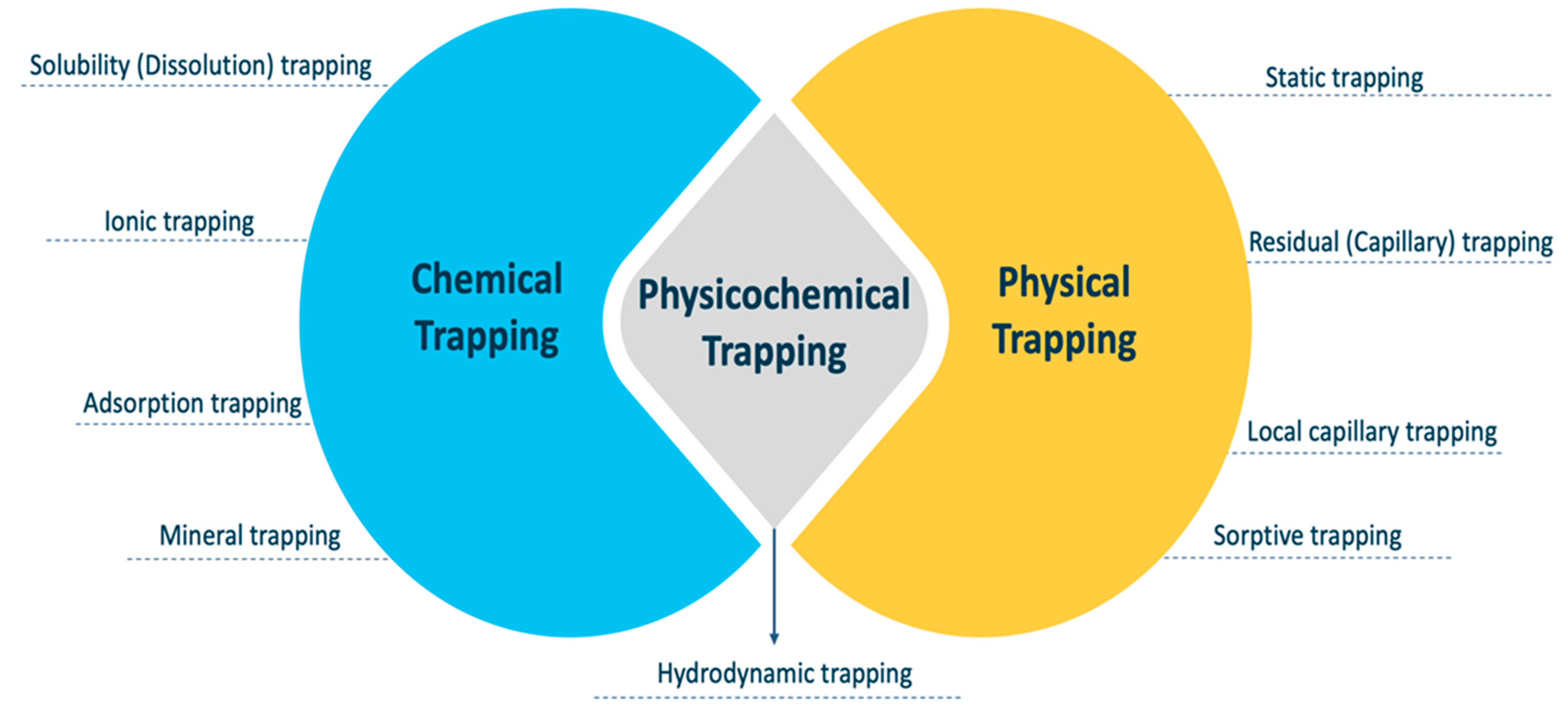
4. Trapping Mechanisms

The ultimate distribution of CO2 in a reservoir is the result of many factors. Structural or stratigraphic trapping, residual trapping, mobility trapping, and mineral trapping are some of the methods. These mechanisms kick in at various points during the CO2 mitigation process’s overall lifetime. For example, structural trapping is in charge of initial CO2 containment and safe storage. Residual and solubility trapping are critical in the dispersion and migration of the CO2 plume, and they help to accelerate geochemical trapping when the CO2 comes into contact with more rock minerals as it expands outwards in the reservoir layer [31]. When geochemical trapping or mining starts, CO2 will no longer be able to exit the reservoir in any way, and the CO2 geological storage may be considered secure since leakage concerns are reduced [17]. The geological and petrophysical properties of the target formation influence CO2 storage capacity, confinement, and injectivity. The supercritical CO2 injected underground is safely trapped by three key trapping methods: (1) chemical trapping, (2) physicochemical trapping, and (3) physical trapping. The effectiveness of the storage process is decided by a combination of trapping processes to ensure long-term storage [31]. Figure 4 displays a matrix of the different CO2-trapping systems, which is important for understanding how these trapping mechanisms interact. In terms of their mechanisms, the chemical and physical trapping methods have a common element, which includes physicochemical trapping. Hydrodynamic trapping is a type of physicochemical trapping that occurs on both the chemical and physical scales. In the following sections, an in-depth explanation is provided for each kind of trapping mechanism.

4.1. Chemical Trapping

Chemical entrapment occurs when CO2 undergoes a sequence of geo-chemical interactions with the formation brine and the rock, causing it to alter its physical and chemical characteristics and to cease to exist in either the mobile or immobile phase. This interaction guarantees that CO2 is no longer present as a distinct phase and boosts storage capacity significantly, making it an appropriate characteristic for long-term storage [24]. There are several trapping mechanisms that fall under geo-chemical trapping, including:
  • Dissolution (solubility) trapping;
  • Ionic trapping;
  • Adsorption trapping;
  • Mineral trapping.

4.1.1. Solubility (Dissolution) Trapping

CO2 dissolves in other fluids in either the supercritical or gaseous phase in the same way as sugar dissolves in tea [24]. Solubility trapping occurs as a consequence of CO2 dissolution in brine, resulting in thick CO2-saturated brine. Thus, it no longer exists as a distinct phase at this moment, which removes any buoyancy impact. After injection, CO2 would travel upwards to the interface between the reservoir and caprock, and then spread laterally beneath the caprock as a distinct phase. When CO2 comes into contact with the ambient formation brine and hydrocarbon, mass transfer takes place, with CO2 dissolving into the brine until an equilibrium condition is attained. In addition, CO2 solubility in water is affected by the salinity, pressure, and temperature of the formation water [84]. Furthermore, CO2 dissolves into water by molecular diffusion at the boundary of the free gas phase and formation water. When water comes into contact with CO2, it becomes saturated with CO2, and the CO2 concentration gradient forms. Because the molecule diffusion coefficient is minimal, this process is significantly slow, where the CO2 will take millions of years to dissolve entirely in brine [85]. Hence, CO2-saturated brine becomes denser than the surrounding reservoir fluids and sinks to the formation’s bottom over time, resulting in more secure CO2 trapping. CO2 dissolution in the aqueous phase produces weak carbonic acid, which decomposes over time into H+ and HCO3 ions (Equation (2)) [24]:
CO 2 ( aq ) + H 2 O H + + HCO 3
It may also be combined with other cations in the formation brines to generate insoluble ionic species, as shown in Equations (3)–(5). The solubility of CO2 in formation water reduces as the temperature and salinity rise [24]:
Ca 2 + +   CO 2 ( aq ) + H 2 O H + + CaHCO 3 ( aq )
Na 2 + +   CO 2 ( aq ) + H 2 O H + + NaHCO 3 ( aq )
Mg 2 + +   CO 2 ( aq ) + 2 H 2 O 2 H + + Mg ( HCO 3 ) 2 ( aq )

4.1.2. Ionic Trapping

Ionic trapping is the process by which dissolved CO2 reacts with reservoir minerals to form carbon-bearing ionic species (i.e., HCO3 and CO32−). This process, called ionic trapping, takes from hundreds to thousands of years to occur [31]. An ionic trapping reaction is common in reservoirs containing calcite and dolomite. In this reaction, H2CO3 reacts with carbonate minerals (e.g., CaCO3), resulting in dissolved Ca2+ and two HCO3 ions in the reservoir brines, with half of the carbon obtained from injected CO2 and the other half from the carbonate mineral. This reaction is known as the ionic trapping of the injected CO2 as HCO3 [86]:
H 2 O + CO 2 + CaCO 3 Ca 2 + + 2 HCO 3

4.1.3. Adsorption Trapping

This trapping mechanism occurs when CO2 adsorbs onto organic materials contained on coals and shales. Particularly in shale gas reservoirs, adsorption trapping may be the predominant mechanism taking place. Furthermore, gas occurs in shale reservoirs in two forms: as free gas and as adsorbed gas. The total organic carbon concentration (TOC) in shales may range from 0.5% to 50%, depending on the kind of shale [87]. Therefore, the quantity of adsorbed gas rises in proportion to the increase in TOC. Furthermore, the adsorption capability of shales increases with the amount of clay present [88,89]. Given the heterogeneity of shale gas reservoirs, the adsorption capacity may vary from 20% to 85%, depending on the TOC and clay concentration [90]. In shale gas reservoirs, intermolecular interactions exist between gas molecules (mostly CH4 and its impurities, or CO2 if it is sequestered) and the solid surface of shales, resulting in the formation of gas bubbles (including organic materials and clays). The process of gas accumulation on a solid surface is known as adsorption when the intermolecular interactions between gas molecules are stronger than the forces between the gas molecules in the surrounding medium [91]. The gas molecules that have been adsorbed are referred to as “adsorbate,” and the solid substance is referred to as “adsorbent” [92]. Adsorption rises in response to a fall in temperature or a rise in pressure. Adsorbed gas is released during desorption, which occurs in the opposite scenario [93]. The adsorption process is exothermic, whereas the desorption process is endothermic [92]. Adsorption and desorption become critical for generating gas from shale gas reservoirs or sequestering CO2 into shale gas reservoirs, depending on TOC and clay concentration. In the event that horizontal wells and hydraulic fracturing are successfully completed, desorption will occur from shale surfaces to matrix pores and fractures, due to a decrease in reservoir pressure as a result of increased production [94]. Desorbed gas and free gas move into the matrix and subsequently into the wellbore, respectively. If CO2 is sequestered in a shale gas reservoir, the process is reversible. Therefore, understanding flow dynamics in shale gas reservoirs requires an understanding of the adsorption and desorption processes [95].

4.1.4. Mineral Trapping

Mineral entrapment is the process by which CO2 is incorporated into a stable mineral phase via interactions with other minerals and organic materials in the formation. Over time, the CO2 injected into the formation water will dissolve and trigger a range of geological processes. Some of these reactions may be advantageous, assisting in chemically containing or “trapping” CO2 as dissolved species and the production of new carbonate minerals; others may be detrimental, assisting in CO2 migration [96]. It is critical to comprehend the cumulative effect of these opposing processes. However, these processes will be influenced by the structure, mineralogy, and hydrogeology of the existing lithologies [97]. CO2 in the aqueous phase generates a weak acid that combines with rock minerals to form bicarbonate ions with a variety of cations depending on the formation’s mineralogy. The following is an example of such a process using potassium basic silicate (Equation (7)) and calcium (Equation (8)) [24]:
3 K feldspar + 2 CO 2 ( aq ) + 2 H 2 O Muscovite + 6 Quartz + 2 K + + 2 HCO 3
Ca 2 + +   CO 2 ( aq ) + H 2 O Calcite + 2 H +
According to the mineralogy of the rock formations, precipitation of CO2 minerals is inevitably generated by chemical interactions with the rock formations themselves [24]. The feasibility of CO2 sequestration forecasts is thus dependent on the accuracy of the geochemical modeling of these events [98]. Because of the dependence of this trapping process on the minerals in the rock, the pressure of the gas, the temperature, and the porosity of the rock, it has been discovered to cause considerable variations in the permeability and porosity of the rock [99].

4.2. Physicochemical Trapping

The bridge between the chemical and physical pathways is physicochemical entrapment. It is important to note that the hydrodynamic trapping aspect is present in all of these methods. The process of storing the CO2 via the interaction of all of the many processes that might occur along a migration route is referred to as hydrodynamic trapping [100].

Hydrodynamic Trapping

This trapping mechanism refers to the interaction of various processes when CO2 is injected into the reservoir or saline formations. It may move extremely slowly for a long time before being trapped by residual, solubility, or mineral trapping. It is the link between chemical and physical trapping mechanisms. In saline formations, hydrodynamic trapping may happen even if there is not a definitive closed trap; it only has to be in an area where fluids move extremely slowly over a very long distance. Because CO2 has a lower density than water, it is able to displace the salty formation water when it is injected into a formation. It then migrates upwards buoyantly because it is lighter than the water. When it reaches the top of the formation, it continues moving as a distinct phase until it is either trapped as residual CO2 saturation or in local structural or stratigraphic traps inside the formation that is sealing it. Over the course of a longer period of time, considerable amounts of CO2 will dissolve in the formation water and subsequently move with the groundwater [31]. When there is a large distance between the deep injection site and the end of the overlaying impermeable formation, such as when there are hundreds of kilometers between them, the amount of time it takes for fluid to travel from the deep basin to the surface may be measured in millions of years [101]. Many researchers and academics are of the opinion that hydrodynamic trapping may be placed in either the category of chemical or physical trapping. Nevertheless, it refers to the common bridging point between the systems that were previously discussed. When the CO2 is injected into the reservoirs, it has the potential to linger there for a significant amount of time while only moving extremely slowly. Eventually, it may get trapped due to residual (physical trapping), solubility, or mineral entrapment (chemical trapping).

4.3. Physical Trapping

Physical entrapment is a method in which CO2 retains its physical properties after being injected into an aquifer or reservoir, and the flow of CO2 is impeded by a physical low-permeability barrier. The physical trapping mechanisms may be subdivided into the following [24,102]:
  • Static trapping;
  • Residual (capillary) trapping;
  • Local capillary trapping;
  • Sorption trapping.

4.3.1. Static Trapping

Static trapping refers to structural trapping, which is the most common kind of trapping seen during geological sequestration, and a similar process has kept oil and gas safe below for centuries. Anticlines coated with caprocks (an ultra-low-permeability layer), stratigraphic traps with/without sealed faults, are used for CO2 storage as a mobile phase or supercritical fluid. It is critical to maximize this storage mechanism in order to guarantee that the injected CO2 stays underground for up to dozens of years after injection [102,103]. Viscous forces are the dominating factors for CO2 migration throughout the injection procedure in the desired formation; CO2 is then stored as a function of depth in either the supercritical or gas phase at the corresponding pressure and temperature [24]. When the injection is stopped, the supercritical CO2 tends to migrate upward through the porous and permeable rock due to the buoyancy effect caused by its density difference compared to other reservoir fluids, and laterally via preferential pathways until it reaches a caprock, fault, or other sealed discontinuity [104], which will eventually inhibit additional CO2 movement.

4.3.2. Residual (Capillary) Trapping

During residual capillary trapping, when CO2 is first introduced into the reservoir, it initially displaces the brine. However, when the injection is stopped, the CO2 moves in two directions: upward due to density differences and laterally due to viscous forces. Thus, the wetting phase (brine) is introduced into the pores through the less-wetting phase (CO2). Then, the brine starts displacing the CO2, resulting in considerable CO2 saturation that becomes trapped in tiny clusters of pores [24]. CO2 that has been detached is then locked in an immobile phase. This technique of trapping is referred to as residual trapping or capillary trapping [96]. Furthermore, as reported by Saadatpoor et al. [105], the surface tension between the CO2 and brine serves to block CO2 transport, resulting in a greater capillary entry pressure than the normal rock pressure. Therefore, CO2 becomes trapped in the pores at this moment due to residual gas saturation. The snap-off and gas trapping occurs as a result of the existence of an imbibition saturation path, as the plume leaves behind a trail of immobile CO2 as it rises [106]. Additionally, residual trapping is often encountered in rocks with microcapillary heterogeneities. Recent research indicates that capillary trapping is a more efficient short-term CO2-trapping process than other short-term CO2-trapping mechanisms [107,108]. Its effectiveness is owed to the presence of stronger capillary forces than buoyant forces, which results in CO2 appearing as pore-scale bubbles rather than being trapped by a slightly weakened caprock. Additional findings show that the residual trapping may severely restrict the mobility of injected CO2, leading to a considerable proportion of CO2 trapping in the hysteresis model. Furthermore, residual gas was shown to have a significant impact on CO2 storage [96].

4.3.3. Local Capillary Trapping

CO2 is trapped by local capillary barriers in a process known as local capillary trapping (LCT). It occurs when a saline aquifer’s permeability and capillary entry pressure are spatially variable, allowing bulk-phase CO2 to move across it due to buoyancy [109]. This trapping mechanism is considered when addressing the inherent heterogeneity of capillary pressure in a specific storage formation [105]. LCT is a type of trapping mechanism that takes place when CO2 is held in place by capillary walls. The saline aquifer with spatially variable characteristics experiences buoyancy-driven bulk-phase CO2 migration, resulting in this phenomenon (permeability and capillary entry pressure). Furthermore, the saturation of the stored CO2 is greater than that of the residual phase, making it ideal for CO2 sequestration [105].

4.3.4. Sorptive Trapping

Sorptive trapping occurs when CO2 is sorbed into an accessible pore space bulk due to a weak physical interaction. Sorption and structural entrapment are two processes that are considered complementary, despite the fact that they take place in the same pore spaces. It is important to note that a sorbed layer will cover a certain volume of the pore space depending on its physical parameters (density and volume). Because of this, the amount of pore space that is accessible to bulk CO2 is decreased. If the sorbed phase density is greater than the bulk density, any storage capacity will benefit from this trapping process, since part of the injected CO2 will not contribute to pressure building and will instead improve the total storage capacity, regardless of the storage capacity [110]. Furthermore, while utilizing manometric and gravimetric sorption devices, as well as neutron diffraction methods, it has been shown in various investigations [70,111] using high pressures (>10 MPa) that the excess sorption capacity may turn negative. This indicates that the average density of the sorbed layer is lower than the average density of bulk CO2, and thus, the same quantity of fluid in the sorbed layer will occupy a greater volume than the average density of bulk CO2. In addition, Busch et al. [110] argued that an immediate practical implication is that the same amount of injected CO2 will result in greater pressures in a reservoir with negative excess sorption capacity.

5. Conclusions

CCS is an important approach for lowering CO2 emissions into the atmosphere. Continuously increasing CO2 emissions have been highlighted as a significant potential source of global concern, while CGS presents a plausible solution for tackling the world’s current huge environmental concern. The threat of global warming has become a real concern. Several governments have acknowledged that our planet is in danger of losing its atmosphere, and that this must be handled. The issue is not just scientific, but also has ramifications in other areas of human activity. We present the reader with the most recent information on CO2 storage science and technology in this review. From a scientific standpoint, the knowledge of the mechanisms involved in the process has substantially improved over time. There are three basic types of trapping mechanisms: (1) chemical, (2) physical, and (3) physicochemical. Each of these categories has been further categorized in detail depending on the contribution they make towards CO2 storage in this review. Each CO2-trapping mechanism is vital and serves a function that is unique to the type of formation. The trapping technique that ensures long-term CO2 capture, storage, and security with minimal leakage is crucial from a variety of perspectives. For instance, mineral trapping is the safest means of storage, but it might take hundreds of years or even thousands of years for it to occur. Therefore, understanding how these trapping mechanisms work in terms of their physics and chemistry would establish a baseline towards:
  • Utilizing the science to understand the trapping mechanisms’ contribution to maximize the CO2 storage capacity;
  • Taking a significant step forward in modeling multi-phase flow systems for carbon storage by integrating the chemical, physical, and physiochemical interactions via a thorough investigation of the parameters that optimize storage capacity potential;
  • Examining the dynamics of CO2 plumes and their contribution to different trapping mechanisms in unconventional depleted shale reservoirs or coal seams;
  • Developing an integrated model that incorporates all of the aforementioned trapping processes and evaluates their trapping storage capability, particularly in tight unconventional formations such as shale or coal seams.

Author Contributions

Conceptualization, F.A.H. and H.B.; methodology, F.A.H.; software, F.A.H.; validation, F.A.H., H.B. and M.A.D.; formal analysis, F.A.H.; investigation, F.A.H. and H.B.; resources, F.A.H. and H.B.; data curation, F.A.H. and H.B.; writing—original draft preparation, F.A.H.; writing—review and editing, F.A.H. and H.B.; visualization, F.A.H., H.B. and M.A.D.; supervision, H.B.; project administration, H.B.; funding acquisition, F.A.H. and H.B. All authors have read and agreed to the published version of the manuscript.

Funding

This research received no external funding.

Data Availability Statement

Not applicable.

Acknowledgments

We would like to thank Khalifa University of Science and Technology for the scholarship provided to the first author.

Conflicts of Interest

The authors declare no conflict of interest.

References

  1. Hepple, R.P.; Benson, S.M. Geologic storage of carbon dioxide as a climate change mitigation strategy: Performance requirements and the implications of surface seepage. Environ. Geol. 2005, 47, 576–585. [Google Scholar] [CrossRef]
  2. Chaves, G. Simulation of CO2 Sequestration in Deep Saline Aquifers; New Mexico Institute of Mining and Technology: Socorro, New Mexico, 2011. [Google Scholar]
  3. Lapillonne, B.; Chateau, B.; Criqui, P.; Kitous, A.; Menanteau, P.; Mima, S.; Gusbin, D.; Gilis, S.; Soria, A.; Russ, P.; et al. World Energy Technology Outlook-2050-WETO-H2; No. halshs-00121063; Bruxelles: Luxembourg, 2007; Available online: https://halshs.archives-ouvertes.fr/halshs-00121063 (accessed on 12 April 2021).
  4. Zhang, B.; Wang, Z.; Wang, B. Energy production, economic growth and CO2 emission: Evidence from Pakistan. Nat. Hazards 2018, 90, 27–50. [Google Scholar]
  5. Pachauri, R.K.; Allen, M.R.; Barros, V.R.; Broome, J.; Cramer, W.; Christ, R.; Church, J.A.; Clarke, L.; Dahe, Q.; Dasgupta, P.; et al. Climate Change 2014: Synthesis Report. Contribution of Working Groups I, II and III to the Fifth Assessment Report of the Intergovernmental Panel on Climate Change; Pachauri, R., Meyer, L., Eds.; IPCC: Geneva, Switzerland, 2014; 151p, ISBN 978-92-9169-143-2. [Google Scholar]
  6. Murshed, M.; Alam, R.; Ansarin, A. The environmental Kuznets curve hypothesis for Bangladesh: The importance of natural gas, liquefied petroleum gas, and hydropower consumption. Environ. Sci. Pollut. Res. 2021, 28, 17208–17227. [Google Scholar] [CrossRef]
  7. Peridas, G.; Schmidt, B.M. The role of carbon capture and storage in the race to carbon neutrality. Electr. J. 2021, 34, 106996. [Google Scholar] [CrossRef]
  8. Salvi, B.L.; Jindal, S. Recent developments and challenges ahead in carbon capture and sequestration technologies. SN Appl. Sci. 2019, 1, 1–20. [Google Scholar] [CrossRef] [Green Version]
  9. Querini, F.; Dagostino, S.; Morel, S.; Rousseaux, P. Greenhouse gas emissions of electric vehicles associated with wind and photovoltaic electricity. Energy Procedia 2012, 20, 391–401. [Google Scholar] [CrossRef] [Green Version]
  10. Rubin, E.; De Coninck, H. IPCC Special Report on Carbon Dioxide Capture and Storage; TNO (2004): Cost Curves for CO2 Storage, Part 2; Cambridge University Press: Cambridge, UK, 2005; p. 14. [Google Scholar]
  11. Figueroa, J.D.; Fout, T.; Plasynski, S.; McIlvried, H.; Srivastava, R.D. Advances in CO2 capture technology—The US Department of Energy’s Carbon Sequestration Program. Int. J. Greenh. Gas Control 2008, 2, 9–20. [Google Scholar] [CrossRef]
  12. Smit, B.; Reimer, J.A.; Oldenburg, C.M.; Bourg, I.C. Introduction to Carbon Capture and Sequestration; Imperial College Press: London, UK, 2014; Volume 1. [Google Scholar]
  13. Marchetti, C. On geoengineering and the CO2 problem. Clim. Chang. 1977, 1, 59–68. [Google Scholar] [CrossRef] [Green Version]
  14. Brewer, P.G. A changing ocean seen with clarity. Proc. Natl. Acad. Sci. USA 2009, 106, 12213–12214. [Google Scholar] [CrossRef] [PubMed] [Green Version]
  15. Bachu, S.; Adams, J.J. Sequestration of CO2 in geological media in response to climate change: Capacity of deep saline aquifers to sequester CO2 in solution. Energy Convers. Manag. 2003, 44, 3151–3175. [Google Scholar] [CrossRef]
  16. Bachu, S.; Gunter, W.D. Overview of acid-gas injection operations in western Canada. In Greenhouse Gas Control Technologies; Elsevier Science Ltd.: Amsterdam, The Netherlands, 2005; Volume 7, pp. 443–448. [Google Scholar]
  17. Vishal, V.; Singh, T. Geologic carbon sequestration. Environ. Geosci. 2016, 16. [Google Scholar] [CrossRef]
  18. Carter, K.M.; Harper, J.A.; Schmid, K.W.; Kostelnik, J. Unconventional natural gas resources in Pennsylvania: The backstory of the modern Marcellus Shale play. Environ. Geosci. 2011, 18, 217–257. [Google Scholar] [CrossRef] [Green Version]
  19. Al Hameli, F.; Suboyin, A.; Al Kobaisi, M.; Rahman, M.M.; Haroun, M. Modeling Fracture Propagation in a Dual-Porosity System: Pseudo-3D-Carter-Dual-Porosity Model. Energies 2022, 15, 6779. [Google Scholar] [CrossRef]
  20. Sha, Z.; Bai, Y.; Li, R.; Lan, H.; Zhang, X.; Li, J.; Liu, X.; Chang, S.; Xie, Y. The global carbon sink potential of terrestrial vegetation can be increased substantially by optimal land management. Commun. Earth Environ. 2022, 3, 8. [Google Scholar] [CrossRef]
  21. IEA. CO2 Emissions from Energy Combustion and Industrial Processes, 1900–2021; IEA: Paris, France; Available online: https://www.iea.org/data-and-statistics/charts/co2-emissions-from-energy-combustion-and-industrial-processes-1900-2021 (accessed on 12 April 2021).
  22. Azarabadi, H.; Lackner, K.S. Postcombustion capture or direct air capture in decarbonizing US natural gas power? Environ. Sci. Technol. 2020, 54, 5102–5111. [Google Scholar] [CrossRef]
  23. Herzog, H.; Golomb, D. Carbon capture and storage from fossil fuel use. Encycl. Energy 2004, 1, 277–287. [Google Scholar]
  24. Ajayi, T.; Gomes, J.S.; Bera, A. A review of CO2 storage in geological formations emphasizing modeling, monitoring and capacity estimation approaches. Pet. Sci. 2019, 16, 1028–1063. [Google Scholar] [CrossRef] [Green Version]
  25. Herzog, H. Carbon Dioxide Capture and Storage; Typset by SPi: Chennai, India, 2009; pp. 246–283. [Google Scholar]
  26. CO2 Storage Resource Catalogue Cycle 2-2021, OGCI. Available online: https://www.ogci.com/co2-storage-resource-catalogue/ (accessed on 12 April 2021).
  27. Yadav, S.; Mondal, S.S. A review on the progress and prospects of oxy-fuel carbon capture and sequestration (CCS) technology. Fuel 2022, 308, 122057. [Google Scholar] [CrossRef]
  28. Litynski, J.T.; Klara, S.M.; McIlvried, H.G.; Srivastava, R.D. An overview of terrestrial sequestration of carbon dioxide: The United States Department of Energy’s fossil energy R&D program. Clim. Chang. 2006, 74, 81–95. [Google Scholar]
  29. Thomson, A.M.; Izaurralde, R.C.; Smith, S.J.; Clarke, L.E. Integrated estimates of global terrestrial carbon sequestration. Glob. Environ. Chang. 2008, 18, 192–203. [Google Scholar] [CrossRef]
  30. Herzog, H.; Drake, E.; Adams, E. CO Capture, Reuse, and Storage Technologies. In Citeseer1997; DE-AF22-96PC01257; Massachusetts Institute of Technology: Cambridge, MA, USA, 1997. [Google Scholar]
  31. Metz, B.; Davidson, O.; De Coninck, H.C.; Loos, M.; Meyer, L. IPCC Special Report on Carbon Dioxide Capture and Storage; Cambridge University Press: Cambridge, UK, 2005. [Google Scholar]
  32. Celia, M.A.; Nordbotten, J.M. Practical modeling approaches for geological storage of carbon dioxide. Groundwater 2009, 47, 627–638. [Google Scholar] [CrossRef] [PubMed]
  33. Myer, L. Global status of geologic CO2 storage technology development. In United States Carbon Sequestration Council Report July, 2011; 2011; Available online: http://carboncap-cleantech.com/articles/CCS/16%20Global-status-of-geologic-CO2-storage-technology-development.pdf (accessed on 10 April 2021).
  34. Span, R.; Wagner, W. A new equation of state for carbon dioxide covering the fluid region from the triple-point temperature to 1100 K at pressures up to 800 MPa. J. Phys. Chem. Ref. Data 1996, 25, 1509–1596. [Google Scholar] [CrossRef] [Green Version]
  35. Chadwick, R.A.; Noy, D.J.; Holloway, S. Flow processes and pressure evolution in aquifers during the injection of supercritical CO2 as a greenhouse gas mitigation measure. Pet. Geosci. 2009, 15, 59–73. [Google Scholar] [CrossRef]
  36. Bachu, S. Screening and ranking of sedimentary basins for sequestration of CO2 in geological media in response to climate change. Environ. Geol. 2003, 44, 277–289. [Google Scholar] [CrossRef]
  37. Kaszuba, J.P.; Janecky, D.R. Geochemical impacts of sequestering carbon dioxide in brine formations. Carbon Sequestration Its Role Glob. Carbon Cycle 2009, 183, 239–248. [Google Scholar]
  38. Van der Meer, L.G.H. Investigations regarding the storage of carbon dioxide in aquifers in the Netherlands. Energy Convers. Manag. 1992, 33, 611–618. [Google Scholar] [CrossRef]
  39. Doughty, C.; Freifeld, B.M.; Trautz, R.C. Site characterization for CO2 geologic storage and vice versa: The Frio brine pilot, Texas, USA as a case study. Environ. Geol. 2008, 54, 1635–1656. [Google Scholar] [CrossRef]
  40. Leung, D.Y.; Caramanna, G.; Maroto-Valer, M.M. An overview of current status of carbon dioxide capture and storage technologies. Renew. Sustain. Energy Rev. 2014, 39, 426–443. [Google Scholar] [CrossRef] [Green Version]
  41. Solomon, S.; Carpenter, M.; Flach, T.A. Intermediate storage of carbon dioxide in geological formations: A technical perspective. Int. J. Greenh. Gas Control 2008, 2, 502–510. [Google Scholar] [CrossRef]
  42. Bachu, S. Sequestration of CO2 in geological media: Criteria and approach for site selection in response to climate change. Energy Convers. Manag. 2000, 41, 953–970. [Google Scholar] [CrossRef]
  43. Pruess, K. Numerical Simulation of Leakage from a Geologic Disposal Reservoir for CO2, with Transitions between Super-and Sub-Critical Conditions; Lawrence Berkeley National Laboratory: Berkeley, CA, USA, 2003.
  44. Bandilla, K.W.; Celia, M.A.; Birkholzer, J.T.; Cihan, A.; Leister, E.C. Multiphase modeling of geologic carbon sequestration in saline aquifers. Groundwater 2015, 53, 362–377. [Google Scholar] [CrossRef] [PubMed]
  45. Michael, K.; Golab, A.; Shulakova, V.; Ennis-King, J.; Allinson, G.; Sharma, S.; Aiken, T. Geological storage of CO2 in saline aquifers—A review of the experience from existing storage operations. Int. J. Greenh. Gas Control 2010, 4, 659–667. [Google Scholar] [CrossRef]
  46. Herzog, H.; Drake, E.; Tester, J.; Rosenthal, R. A research needs assessment for the capture, utilization, and disposal of carbon dioxide from fossil fuel-fired power plants. In Report to the US Department of Energy; Grant No. DEFG02-92ER30194; MIT Energy Laboratory: Cambridge, UK, 1993. [Google Scholar]
  47. Davis, L.A.; Graham, A.L.; Parker, H.W.; Abbott, J.R.; Ingber, M.S.; Mammoli, A.A.; Mondy, L.A.; Guo, Q.; Abou-Sayed, A. Maximizing Storage Rate and Capacity and Insuring the Environmental Integrity of Carbon Dioxide Sequestration in Geological Reservoirs; Texas Tech University: Lubbock, TX, USA, 2005. [Google Scholar]
  48. Johnson, J.W. A solution for carbon dioxide overload. Sci. Technol. Rev. 2000. Available online: http://www.llnl.gov/str/Johnson.html (accessed on 2 May 2021).
  49. Anderson, J.; Bachu, S.; Nimir, H.B.; Basu, B.; Bradshaw, J.; Deguchi, G.; Gale, J.; Von Goerne, G.; Heidug, W.; Holloway, S.; et al. Underground Geological Storage; Cambridge University Press: Cambridge, UK, 2005. [Google Scholar]
  50. Sharma, S.; Agrawal, V.; McGrath, S.; Hakala, J.A.; Lopano, C.; Goodman, A. Geochemical controls on CO2 interactions with deep subsurface shales: Implications for geologic carbon sequestration. Environ. Sci. Process. Impacts 2021, 23, 1278–1300. [Google Scholar] [CrossRef] [PubMed]
  51. Winter, E.M.; Bergman, P.D. Availability of depleted oil and gas reservoirs for disposal of carbon dioxide in the United States. Energy Convers. Manag. 1993, 34, 1177–1187. [Google Scholar] [CrossRef]
  52. Kovscek, A.R. Screening criteria for CO2 storage in oil reservoirs. Pet. Sci. Technol. 2002, 20, 841–866. [Google Scholar] [CrossRef]
  53. Bossie-Codreanu, D.; Le-Gallo, Y.; Duquerroix, J.P.; Doerler, N.; Le Thiez, P. CO2 sequestration in depleted oil reservoirs. In Proceedings of the 6th International Conference on Greenhouse Gas Control Technologies (GHGT-6), Kyoto, Japan, 1–4 October 2002; Gale, J., Kaya, Y., Eds.; 2003; pp. 403–408. [Google Scholar]
  54. Holt, T.; Jensen, J.I.; Lindeberg, E. Underground storage of CO2 in aquifers and oil reservoirs. Energy Convers. Manag. 1995, 36, 535–538. [Google Scholar] [CrossRef]
  55. Bondor, P.L. Applications of carbon dioxide in enhanced oil recovery. Energy Convers. Manag. 1992, 33, 579–586. [Google Scholar] [CrossRef]
  56. Martin, F.D.; Taber, J.J. Carbon dioxide flooding. J. Pet. Technol. 1992, 44, 396–400. [Google Scholar] [CrossRef]
  57. Moritis, G. CO2 sequestration adds new dimension to oil, gas production. Oil Gas J. 2003, 101, 71–83. [Google Scholar]
  58. Klins, M.A.; Farouq Ali, S.M. Heavy oil production by carbon dioxide injection. J. Can. Pet. Technol. 1982, 21, 64–72. [Google Scholar] [CrossRef]
  59. Klins, M.A. Carbon Dioxide Flooding; D. Reidel Publishing Co.: Boston, MA, USA, 1984; p. 267. [Google Scholar]
  60. Taber, J.J.; Martin, F.D.; Seright, R.S. EOR screening criteria revisited-part 1: Introduction to screening criteria and enhanced recovery fields projects. SPE Reserv. Eng. 1997, 12, 189–198. [Google Scholar] [CrossRef] [Green Version]
  61. Shaw, J.C.; Bachu, S. Screening, evaluation and ranking of oil reserves suitable for CO2 flood EOR and carbon dioxide sequestration. J. Can. Pet. Technol. 2002, 41, 51–61. [Google Scholar] [CrossRef]
  62. Metcalfe, R.S. Effects of impurities on minimum miscibility pressures and minimum enrichment levels for CO2 and rich gas displacements. SPE J. 1982, 22, 219–225. [Google Scholar] [CrossRef]
  63. Williams, D.J. Greenhouse Gas Control Technologies: Proceedings of the 5th International Conference on Greenhouse Gas Control Technologies; Csiro Publishing: Melbourne, Australia, 2001. [Google Scholar]
  64. Naik, G.C. Tight gas reservoirs–an unconventional natural energy source for the future. Accessado Em 2003, 1, 2008. [Google Scholar]
  65. Lan, Y.; Yang, Z.; Wang, P.; Yan, Y.; Zhang, L.; Ran, J. A review of microscopic seepage mechanism for shale gas extracted by supercritical CO2 flooding. Fuel 2019, 238, 412–424. [Google Scholar] [CrossRef]
  66. Prusty, B.K. Sorption of methane and CO2 for enhanced coalbed methane recovery and carbon dioxide sequestration. J. Nat. Gas Chem. 2008, 17, 29–38. [Google Scholar] [CrossRef]
  67. Godec, M.; Koperna, G.; Petrusak, R.; Oudinot, A. Enhanced gas recovery and CO2 storage in gas shales: A summary review of its status and potential. Energy Procedia 2014, 63, 5849–5857. [Google Scholar] [CrossRef] [Green Version]
  68. Tao, Z.; Clarens, A. Estimating the carbon sequestration capacity of shale formations using methane production rates. Environ. Sci. Technol. 2013, 47, 11318–11325. [Google Scholar] [CrossRef]
  69. Liu, J.; Xie, L.; Yao, Y.; Gan, Q.; Zhao, P.; Du, L. Preliminary study of influence factors and estimation model of the enhanced gas recovery stimulated by carbon dioxide utilization in shale. ACS Sustain. Chem. Eng. 2019, 7, 20114–20125. [Google Scholar] [CrossRef]
  70. Busch, A.; Gensterblum, Y. CBM and CO2-ECBM related sorption processes in coal: A review. Int. J. Coal Geol. 2011, 87, 49–71. [Google Scholar] [CrossRef]
  71. Mukherjee, M.; Misra, S. A review of experimental research on Enhanced Coal Bed Methane (ECBM) recovery via CO2 sequestration. Earth-Sci. Rev. 2018, 179, 392–410. [Google Scholar] [CrossRef]
  72. Pan, Z.; Ye, J.; Zhou, F.; Tan, Y.; Connell, L.D.; Fan, J. CO2 storage in coal to enhance coalbed methane recovery: A review of field experiments in China. Int. Geol. Rev. 2018, 60, 754–776. [Google Scholar] [CrossRef]
  73. Reeves, S.R. Geological sequestration of CO2 in deep, unmineable coalbeds: An integrated research and commerical-scale field demonstration project. In SPE Annual Technical Conference and Exhibition; OnePetro: New Orleans, Louisiana, September 2001. [Google Scholar] [CrossRef]
  74. Saghafi, A.; Faiz, M.; Roberts, D. CO2 storage and gas diffusivity properties of coals from Sydney Basin, Australia. Int. J. Coal Geol. 2007, 70, 240–254. [Google Scholar] [CrossRef]
  75. Gunter, W.D.; Gentzis, T.; Rottenfusser, B.A.; Richardson, R.J.H. Deep coalbed methane in Alberta, Canada: A fuel resource with the potential of zero greenhouse gas emissions. Energy Convers. Manag. 1997, 38, S217–S222. [Google Scholar] [CrossRef]
  76. Sun, Y.; Li, S.; Sun, R.; Liu, X.; Pu, H.; Zhao, J. Study of CO2 Enhancing Shale Gas Recovery Based on Competitive Adsorption Theory. ACS Omega 2020, 5, 23429–23436. [Google Scholar] [CrossRef]
  77. Khan, C.; Amin, R.; Madden, G. Economic modelling of CO2 injection for enhanced gas recovery and storage: A reservoir simulation study of operational parameters. Energy Environ. Res. 2012, 2, 65–82. [Google Scholar] [CrossRef] [Green Version]
  78. Moinfar, A.; Sepehrnoori, K.; Johns, R.T.; Varavei, A. Coupled geomechanics and flow simulation for an embedded discrete fracture model. In SPE Reservoir Simulation Symposium; OnePetro: The Woodlands, TX, USA, February 2013. [Google Scholar] [CrossRef]
  79. Sun, H.; Yao, J.; Gao, S.H.; Fan, D.Y.; Wang, C.C.; Sun, Z.X. Numerical study of CO2 enhanced natural gas recovery and sequestration in shale gas reservoirs. Int. J. Greenh. Gas Control 2013, 19, 406–419. [Google Scholar] [CrossRef]
  80. Liu, F.; Ellett, K.; Xiao, Y.; Rupp, J.A. Assessing the feasibility of CO2 storage in the New Albany Shale (Devonian–Mississippian) with potential enhanced gas recovery using reservoir simulation. Int. J. Greenh. Gas Control 2013, 17, 111–126. [Google Scholar] [CrossRef]
  81. Li, X.; Elsworth, D. Geomechanics of CO2 enhanced shale gas recovery. J. Nat. Gas Sci. Eng. 2015, 26, 1607–1619. [Google Scholar] [CrossRef]
  82. Bacon, D.H.; Yonkofski, C.M.; Schaef, H.T.; White, M.D.; McGrail, B.P. CO2 storage by sorption on organic matter and clay in gas shale. J. Unconv. Oil Gas Resour. 2015, 12, 123–133. [Google Scholar] [CrossRef] [Green Version]
  83. Sang, Q.; Li, Y.; Zhu, C.; Zhang, S.; Dong, M. Experimental investigation of shale gas production with different pressure depletion schemes. Fuel 2016, 186, 293–304. [Google Scholar] [CrossRef]
  84. Chang, Y.B.; Coats, B.K.; Nolen, J.S. A compositional model for CO2 floods including CO2 solubility in water. In Proceedings of the Permian Basin Oil and Gas Recovery Conference, Midland, TX, USA, 12 March 1981; OnePetro: Midland, TX, USA, March 1996. [Google Scholar] [CrossRef]
  85. Lindeberg, E.; Wessel-Berg, D. Vertical convection in an aquifer column under a gas cap of CO2. Energy Convers. Manag. 1997, 38, S229–S234. [Google Scholar] [CrossRef]
  86. Mayer, B.; Shevalier, M.; Nightingale, M.; Kwon, J.S.; Johnson, G.; Raistrick, M.; Hutcheon, I.; Perkins, E. Tracing the movement and the fate of injected CO2 at the IEA GHG Weyburn-Midale CO2 Monitoring and Storage project (Saskatchewan, Canada) using carbon isotope ratios. Int. J. Greenh. Gas Control 2013, 16, S177–S184. [Google Scholar] [CrossRef]
  87. Merey, Ş.; Sınayuç, Ç. Experimental analysis of adsorption capacities and behaviors of shale samples. In 19th International Petroleum and Natural Gas Congress and Exhibition of Turkey; (cp-380); European Association of Geoscientists & Engineers: Antalya, Turkey, 2013. [Google Scholar]
  88. Ross, D.J.; Bustin, R.M. The importance of shale composition and pore structure upon gas storage potential of shale gas reservoirs. Mar. Pet. Geol. 2009, 26, 916–927. [Google Scholar] [CrossRef]
  89. Heller, R.J.; Zoback, M.D. Adsorption, swelling and viscous creep of synthetic clay samples. In Proceedings of the 45th US Rock Mechanics/Geomechanics Symposium, San Francisco, CA, USA, 26–29 June 2011. [Google Scholar]
  90. Lancaster, D.E.; Hill, D. A multi-laboratory comparison of isotherm measurements of Antrim shale samples. In 1993 SCA Conference Paper; No. 9303; Otsego County, MI, USA, 1993; pp. 1–16. [Google Scholar]
  91. Mengal, S.A.; Wattenbarger, R.A. Accounting for adsorbed gas in shale gas reservoirs. In Proceedings of the SPE Middle East Oil and Gas Show and Conference, Manama, Bahrain, 25–28 September 2011; OnePetro: Manama, Bahrain, September 2011. [Google Scholar] [CrossRef]
  92. John Thomas, F.; Crittenden, B. Adsorption Technology and Design; Butterworth-Heinemann, Reed Educational and Professional Publishing: Oxford, UK, 1998. [Google Scholar]
  93. Mohammad, S.; Fitzgerald, J.; Robinson, R.L., Jr.; Gasem, K.A. Experimental uncertainties in volumetric methods for measuring equilibrium adsorption. Energy Fuels 2009, 23, 2810–2820. [Google Scholar] [CrossRef]
  94. Merey, Ş. Analysis of the effect of experimental adsorption uncertainty on CH4 production and CO2 sequestration in Dadas shale gas reservoir by numerical simulations. J. Pet. Sci. Eng. 2019, 178, 1051–1066. [Google Scholar] [CrossRef]
  95. Song, B.; Ehlig-Economides, C.; Economides, M.J. Design of multiple transverse fracture horizontal wells in shale gas reservoirs. In Proceedings of the SPE Hydraulic Fracturing Technology Conference, The Woodlands, TX, USA, 24–26 January 2011; OnePetro: Manama, Bahrain, 2011. [Google Scholar]
  96. Zhang, D.; Song, J. Mechanisms for geological carbon sequestration. Procedia IUTAm 2014, 10, 319–327. [Google Scholar] [CrossRef] [Green Version]
  97. Rochelle, C.A.; Czernichowski-Lauriol, I.; Milodowski, A.E. The impact of chemical reactions on CO2 storage in geological formations: A brief review. Geol. Soc. Lond. Spec. Publ. 2004, 233, 87–106. [Google Scholar] [CrossRef]
  98. Benson, S.M.; Cole, D.R. CO2 sequestration in deep sedimentary formations. Elements 2008, 4, 325–331. [Google Scholar] [CrossRef]
  99. Kampman, N.; Bickle, M.; Wigley, M.; Dubacq, B. Fluid flow and CO2–fluid–mineral interactions during CO2-storage in sedimentary basins. Chem. Geol. 2014, 369, 22–50. [Google Scholar] [CrossRef]
  100. Bachu, S.; Bonijoly, D.; Bradshaw, J.; Burruss, R.; Holloway, S.; Christensen, N.P.; Mathiassen, O.M. CO2 storage capacity estimation: Methodology and gaps. Int. J. Greenh. Gas Control 2007, 1, 430–443. [Google Scholar] [CrossRef] [Green Version]
  101. Bachu, S.; Gunter, W.D.; Perkins, E.H. Aquifer disposal of CO2: Hydrodynamic and mineral trapping. Energy Convers. Manag. 1994, 35, 269–279. [Google Scholar] [CrossRef]
  102. Jiang, X. A review of physical modelling and numerical simulation of long-term geological storage of CO2. Appl. Energy 2011, 88, 3557–3566. [Google Scholar] [CrossRef]
  103. Ambrose, W.A.; Lakshminarasimhan, S.; Holtz, M.H.; Núñez-López, V.; Hovorka, S.D.; Duncan, I. Geologic factors controlling CO2 storage capacity and permanence: Case studies based on experience with heterogeneity in oil and gas reservoirs applied to CO2 storage. Environ. Geol. 2008, 54, 1619–1633. [Google Scholar] [CrossRef]
  104. Han, W.S. Evaluation of CO2 Trapping Mechanisms at the SACROC Northern Platform: Site of 35 Years of CO2 Injection. Ph.D. Thesis, The New Mexico Institute of Mining and Technology, Socorro, NM, USA, 2008. [Google Scholar]
  105. Saadatpoor, E.; Bryant, S.L.; Sepehrnoori, K. New trapping mechanism in carbon sequestration. Transp. Porous Media 2010, 82, 3–17. [Google Scholar] [CrossRef]
  106. Juanes, R.; Spiteri, E.J.; Orr, F.M., Jr.; Blunt, M.J. Impact of relative permeability hysteresis on geological CO2 storage. Water Resour. Res. 2006, 42. [Google Scholar] [CrossRef]
  107. Burnside, N.M.; Naylor, M. Review and implications of relative permeability of CO2/brine systems and residual trapping of CO2. Int. J. Greenh. Gas Control 2014, 23, 1–11. [Google Scholar] [CrossRef] [Green Version]
  108. Lamy, C.; Iglauer, S.; Pentland, C.H.; Blunt, M.J.; Maitland, G. Capillary trapping in carbonate rocks. In Proceedings of the SPE EUROPEC/EAGE Annual Conference and Exhibition, Barcelona, Spain, 14–17 June 2010; OnePetro: Barcelona, Spain, June 2010. [Google Scholar] [CrossRef]
  109. Ren, B. Local capillary trapping in carbon sequestration: Parametric study and implications for leakage assessment. Int. J. Greenh. Gas Control 2018, 78, 135–147. [Google Scholar] [CrossRef]
  110. Busch, A.; Bertier, P.; Gensterblum, Y.; Rother, G.; Spiers, C.J.; Zhang, M.; Wentinck, H.M. On sorption and swelling of CO2 in clays. Geomech. Geophys. Geo-Energy Geo-Resour. 2016, 2, 111–130. [Google Scholar] [CrossRef] [Green Version]
  111. Rother, G.; Ilton, E.S.; Wallacher, D.; Hauβ, T.; Schaef, H.T.; Qafoku, O.; Rosso, K.M.; Felmy, A.R.; Krukowski, E.G.; Stack, A.G.; et al. CO2 sorption to subsingle hydration layer montmorillonite clay studied by excess sorption and neutron diffraction measurements. Environ. Sci. Technol. 2013, 47, 205–211. [Google Scholar] [CrossRef] [PubMed]
Figure 1. Global CO2 emissions (data source: World Energy Technology Outlook 2050 [3]).
Energies 15 07805 g001
Figure 2. Global CO2 emissions in conjunction with CO2 sequestration from 1990 to 2050 (data source: World Energy Technology Outlook 2050 [3]).
Energies 15 07805 g002
Figure 3. CO2 potential storage capacity assessment across the countries (data source: CO2 Storage Resource Catalogue Cycle 2 2021 [26]).
Energies 15 07805 g003
Figure 4. CO2-trapping mechanisms in geological formations.
Energies 15 07805 g004
Table 1. Worldwide potential reservoir capacity for CO2 sequestration.
CO2 Sequestration OptionsStorage Capacity *References
Geological CO2 Sequestration:
Ocean1000–10,000 + GtC[17,23]
Deep saline formations100–10,000 GtC[17,23]
Depleted oil and gas reservoirs100–1000 GtC[17,23]
CO2-EOR61–123 GtC[17]
Coal seams10–1000 GtC[17,23]
Organic-rich shales2.5–25 GtC[18]
Biological CO2 Sequestration:
Terrestrial10–100 GtC[20]
Technological CO2 Sequestration:
Direct air capture (DAC)<0.1 GtC[21,22]
* 1 GtC = 1 billion tons of carbon.
Table 2. Classification of CO2 potential storage resources for the 17 countries (data source: CO2 Storage Resource Catalogue Cycle 2 2021 [26]).
ClassificationCO2 Storage Resource (Gt)Percentage
Stored0.0370.00029%
Capacity0.2170.00167%
Sub-commercial5514.25%
Undiscovered12,40795.75%
Total12,958.25100%
Storage in saline aquifers 12,68498%
Storage in oil and gas fields2742%
Table 3. CO2 supercritical state conditions for injection and storage.
CO2 Supercritical State ConditionsValuesReferences
Temperature31 °C[34]
Pressure7.38 MPa[34]
Density850 kg/m3[36]
Depth Below 800 m[38]
Publisher’s Note: MDPI stays neutral with regard to jurisdictional claims in published maps and institutional affiliations.

