Review

Approaches to Disposal of Nuclear Waste

by
Michael I. Ojovan
1,* and
Hans J. Steinmetz
2
1
Department of Materials, Imperial College London, London SW7 2AZ, UK
2
Faculty of Chemistry and Biotechnology, Aachen University of Applied Sciences, Heinrich-Mußmann-Straße 1, 52428 Jülich, Germany
*
Author to whom correspondence should be addressed.
Energies 2022, 15(20), 7804; https://doi.org/10.3390/en15207804
Submission received: 20 September 2022 / Revised: 18 October 2022 / Accepted: 20 October 2022 / Published: 21 October 2022
(This article belongs to the Special Issue Treatment of Radioactive Waste and Sustainability Energy)

Abstract

:
We present a concise mini overview on the approaches to the disposal of nuclear waste currently used or deployed. The disposal of nuclear waste is the end point of nuclear waste management (NWM) activities and is the emplacement of waste in an appropriate facility without the intention to retrieve it. The IAEA has developed an internationally accepted classification scheme based on the end points of NWM, which is used as guidance. Retention times needed for safe isolation of waste radionuclides are estimated based on the radiotoxicity of nuclear waste. Disposal facilities usually rely on a multi-barrier defence system to isolate the waste from the biosphere, which comprises the natural geological barrier and the engineered barrier system. Disposal facilities could be of a trench type, vaults, tunnels, shafts, boreholes, or mined repositories. A graded approach relates the depth of the disposal facilities’ location with the level of hazard. Disposal practices demonstrate the reliability of nuclear waste disposal with minimal expected impacts on the environment and humans.

1. Introduction

1.1. Nuclear (Radioactive) Waste

Following the definition given by the International Atomic Energy Agency (IAEA) basic safety standard (BSS) “Radiation protection and safety of radiation sources: International basic safety standards” [1], radioactive waste is material that contains, or is contaminated with, radionuclides at activity concentrations greater than clearance levels, as established by the regulatory body, for which, for legal and regulatory purposes, no further use is foreseen. The terms “radioactive waste” and “nuclear waste” are generically used as synonyms in the context of safety and waste management. Nuclear waste, compared with non-nuclear waste, is a material that has levels of radioactivity above clearance levels, and this is the only difference that introduces a complex and highly regulated area of radioactive waste management (RWM). Clearance and/or exemption levels are always established by national authorities of countries although in most cases these are based on the IAEA BSS, which provides a complete list of rather conservative exemption levels for all practically important radionuclides [1].
The wastes that contain, or are contaminated with, radionuclides at activity concentrations below the clearance levels are considered conventionally non-radioactive. The focus point is that the world around us and all materials have some background levels of radioactivity and only the materials and activities that significantly exceed these levels enter regulatory control, whereas the background levels of radiation and substances containing the radionuclides, which in most cases have natural origins, do not present any harm to the environment and humans (if not the opposite). The use of conventionally non-radioactive materials is hence not controlled by nuclear-related regulatory organisations although it can be under the surveillance of many other kinds of regulations and controls, depending on the situation. Correspondingly, waste that is produced by activities involving conventionally non-radioactive materials is considered non-radioactive.

1.2. Consensus on Disposal

There is global consensus of all countries that use nuclear energy to a larger or smaller degree that the only final safe solution (end point) for the long-term management of nuclear waste is through disposal. Disposal is the emplacement of waste in an appropriate facility without the intention to retrieve it, as specified by refs. [1,2,3,4,5,6]. Disposal is also regarded as an almost complete removal of dangerous materials out of any biological cycles (biosphere). Proposals such as the disposal of nuclear waste into outer space or in subduction zones currently look unrealistic [7,8] whereas the disposal into stable geological formations is well-elaborated. Thus, all efforts are directed to organising the disposal in such a way that even in the very far (remote) future the probability of any interference of radionuclides with the biosphere is practically absent or minimised to a negligible degree if potentially envisaged. Generally, the disposal is applied to wastes in a solid form placed in suitable containers. Moreover, the waste may be (and usually is) first immobilised in a durable wasteform. This facilitates safe handling, storage, and disposal and constitutes a part of a multi-barrier approach, which can include the engineered disposal configuration and geological environment, with the aim of minimising any risk of migration of radionuclides within the biosphere. Some countries also use the term disposal to include discharges of limited amounts of effluents to the environment.
The selection of a disposal option depends on many factors, both technical—such as waste characteristics and inventory; and administrative—such as the radioactive waste management policy, overall disposal strategy of waste management in the country, national legislative and regulatory requirements, political decisions and social acceptance, and natural conditions of the country, such as climatic conditions, site characteristics, and the availability of suitable host media [9,10,11].

1.3. Aims of Disposal

The disposal facilities aim to prevent or reduce to the minimum the interaction between the environment and the waste and, most importantly, between the natural waters and the wasteform. There are many ways of doing this, such as via a proper choice of:
(a)
Site (such as using an arid region or unsaturated, mountainous site, etc.);
(b)
Emplacement depth (near-surface, above/below grade, intermediate depth, deep geological);
(c)
Use of water-resistant caps (runoff drainage layer, clay barrier);
(d)
Long-lived containment (borehole disposal), etc.
A primary issue is also the protection of inadvertent human intrusion and the degree to which a combination of depth of disposal, institutional controls, and engineered barriers can be relied upon to prevent or minimise this exposure scenario [12].
Decisions on disposal technology selection typically follow a graded approach with the following main three principles used [10]:
  • Nuclear wastes are disposed of using the simplest disposal concept available, which is consistent with the hazards of waste and for which safety and environmental protection can be demonstrated.
  • The most hazardous wastes are disposed using greater levels of engineering to provide for increased containment and/or are disposed of at greater possible depth to increase isolation from the surface environment.
  • Where existing disposal facilities are available, consideration is given to first using them before developing new disposal facilities.

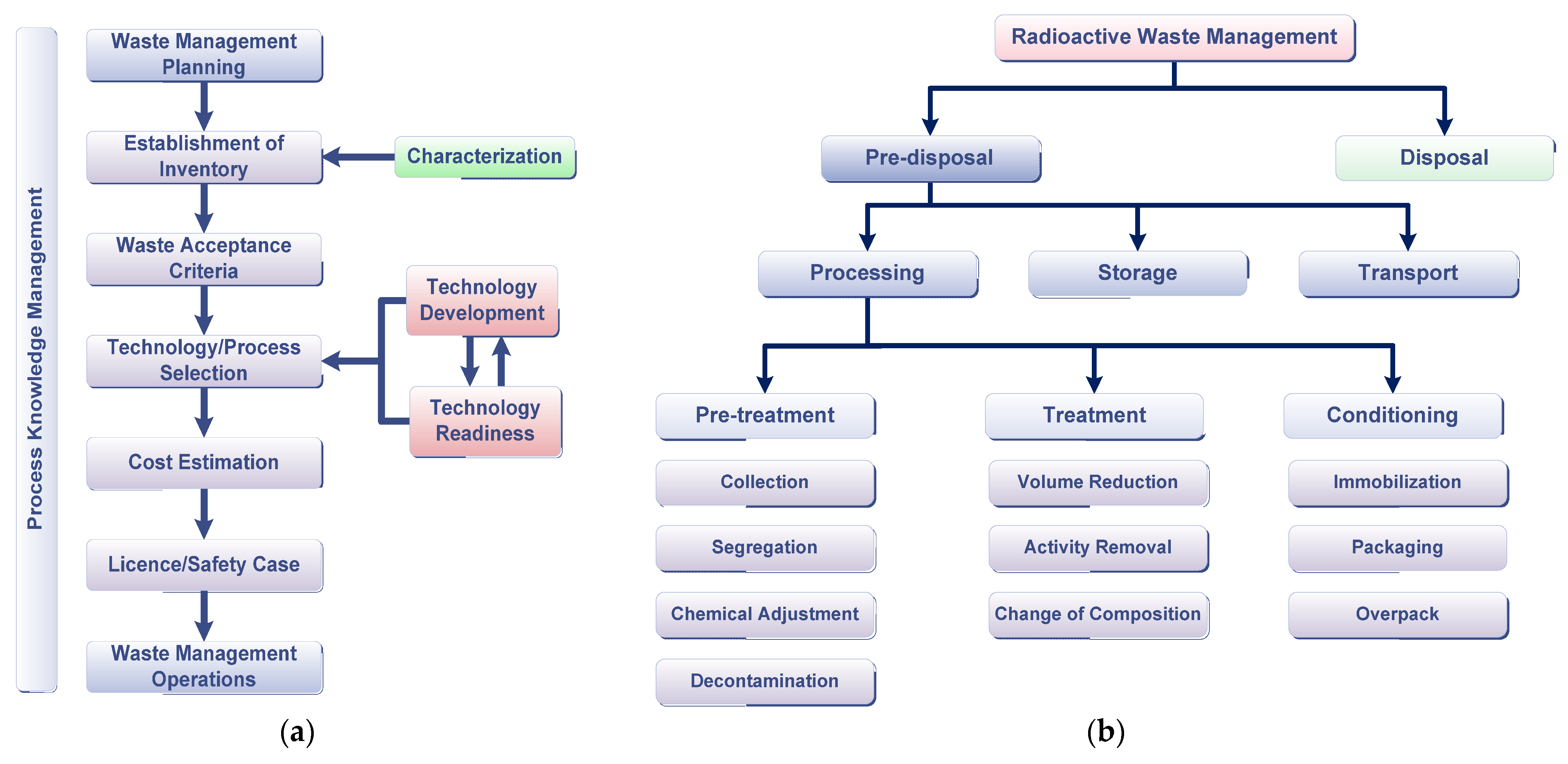
1.4. Disposal as End Point of Management

Nuclear waste management (NWM) comprises all administrative and operational activities involved in the handling, pre-treatment, treatment, conditioning, transport, storage, and disposal of radioactive waste (Figure 1).
NWM is a national responsibility whereas international organisations such as IAEA can only provide assistance to ensure the effective and safe use of nuclear energy. To ensure the long-term viability and public acceptance of nuclear energy and its applications, it is essential that any waste generated is safely and efficiently managed from the point of generation through to disposal.
The end point of NWM is always disposal, i.e., the emplacement of radioactive waste into a facility or location with no intention of retrieval. The key to achieving this is the development of an Integrated Waste Strategy (IWS) [13]. As the NWM is a country responsibility, every single country should have some form of policy and strategy for managing its spent nuclear fuel and radioactive waste [13].
NWM practices including disposal should always comply with IAEA safety principles, which are provided by the IAEA standard SF-1 [14]. The fundamental safety objective set by the IAEA SF-1 standard is to protect people and the environment from the harmful effects of ionizing radiation; however, this needs to be achieved without unduly limiting the operation of facilities or the conduct of activities with the 10 safety principles [14]. The IAEA safety principles provide the basis for requirements and measures for the protection of people and the environment against radiation risks and for the safety of facilities and activities that give rise to radiation risks, including nuclear waste disposal facilities and activities as an integral part of NWM [15].

2. Nuclear Waste Classification for Disposal

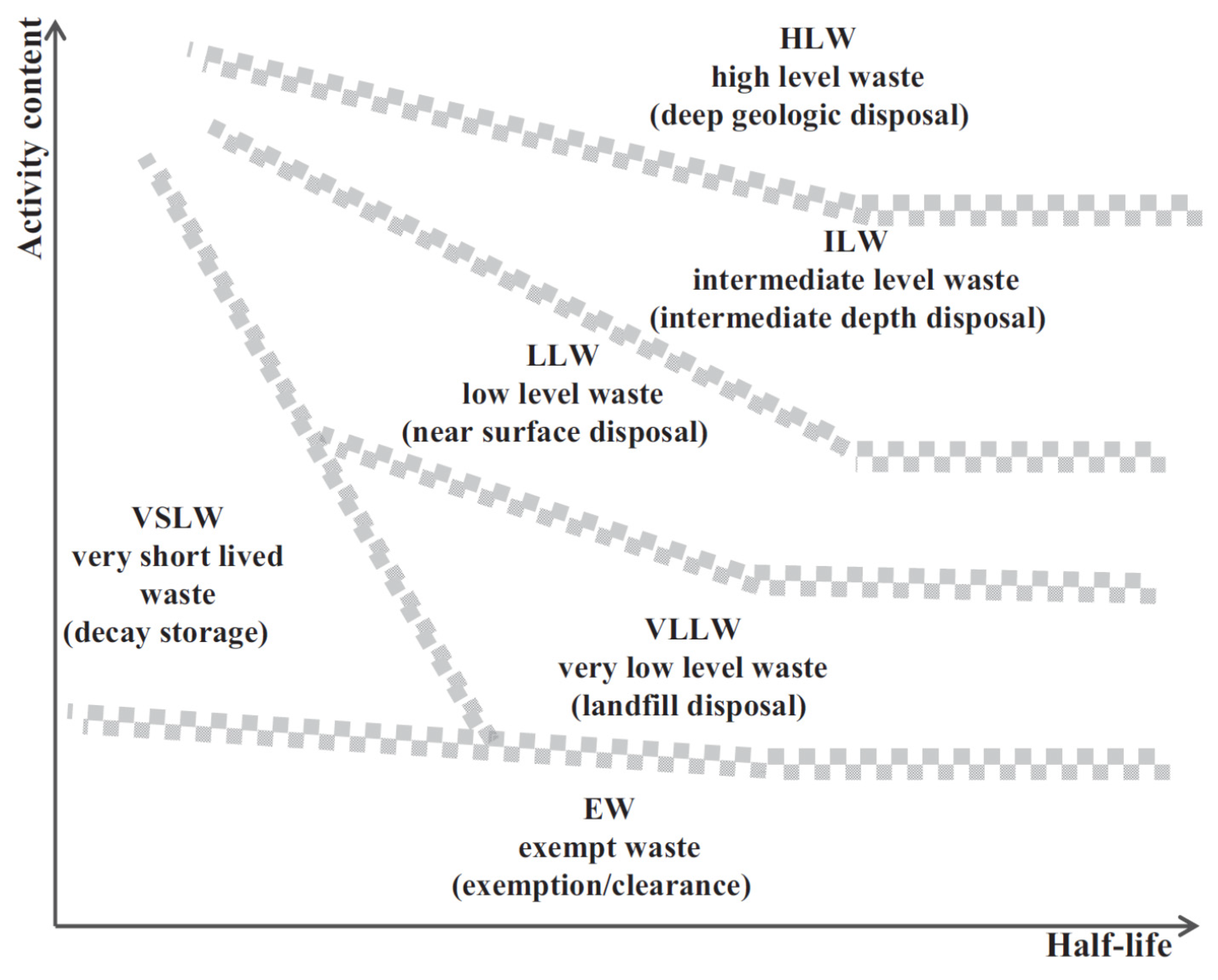
2.1. IAEA Classification

The IAEA has developed a globally accepted generic system of nuclear waste classification, which accommodates various waste types and disposal solutions and gives a useful initial consideration of disposal routes, although it does not prescribe specific disposal solutions for certain waste types, which are always based on specific safety assessment for each disposal facility used [16]. The IAEA nuclear waste classification system (Figure 2) is entirely based on the final or end points of nuclear waste disposal.
At first, the IAEA conventionally divides the radionuclides depending on half-lives of the decay into (a) short-lived and (b) long-lived. Short-lived radionuclides are those with a half-life smaller than 31 years (aiming to include 137Cs, which has a half-life of 30.17 a).
Then, six classes of waste are defined, starting with the lowest, by radionuclide content (activity content in Figure 2, see, e.g., Tables I.1 and I.2 of Ref. [1]), which is the exempt waste (EW) that is represented by conventionally non-radioactive waste materials. In addition to EW, the IAEA classification scheme defines five classes of radioactive waste: very short-lived waste (VSLW), very low-level waste (VLLW), low-level waste (LLW), intermediate-level waste (ILW), and high-level waste (HLW):
  • VSLW is radioactive waste that can be stored for decay over a limited period of no longer than a few years, with subsequent clearance from regulatory control, and typically includes radioactive wastes generated by uses of nuclear energy in research and medicine;
  • VLLW is radioactive waste that does not need a high level of containment and isolation and because of that is suitable for disposal in near-surface landfill type facilities with limited regulatory control. Typical VLLW includes soil and rubble with low levels of activity concentration, which does not usually exceed one hundred times clearance levels for each of the radionuclides present. In some countries, VLLW is disposed of in purpose-built disposal facilities, e.g., these can be in the form of earthen trenches with engineered covers, although it can be disposed of with LLW;
  • LLW has limited amounts of long-lived radionuclides in it and because of that requires robust isolation and containment for periods of up to a few hundred years. LLW is suitable for disposal in engineered near-surface disposal facilities (NSDF). LLW covers a very broad range of waste with long-lived radionuclides only at relatively low levels of activity concentration. LLW is generated in most facilities involved in nuclear power production, nuclear research, and nuclear medicine. It is common practice to dispose of LLW in NSDFs, although options for the disposal of LLW include simplified facilities such as engineered trenches or concrete vaults in which waste containers are placed. An engineered or earthen cap is then placed over the waste containers to minimise water infiltration. The NSDFs are subject to surveillance until the hazard associated with the nuclear waste has declined to acceptable (e.g., clearance) levels. Some countries prefer disposing of LLW in sub-surface facilities or co-locating LLW with ILW or spent nuclear fuel (SNF) in deeper facilities;
  • ILW is radioactive waste that requires a greater degree of containment and isolation than that provided by NSDFs although it needs no provision for radiogenic heat dissipation. The ILW requires disposal at greater depths, of the order of from tens of metres to at one or even a few hundred metres. Moreover, disposal at depths of greater than several tens of metres is generally considered to be the most appropriate option for ILW. Co-disposal of ILW with SNF and HLW is an effective option considered in many countries. A precise boundary between LLW and ILW does not exists although a limit content of 400 Bq/g on average and up to 4000 Bq/g for individual packages for long-lived alpha emitting radionuclides has been adopted in many countries following the recommendation of IAEA [16]. The actual boundary-limiting levels result in each specific case from the performance and safety analysis reports and cannot be generic to all facilities. For long-lived beta- and/or gamma-emitting radionuclides, e.g., 14C, 36Cl, 63Ni, 93Zr, 94Nb, 99Tc, and 129I, the allowable average activity concentrations may be considerably higher (up to tens of kBq/g) although they are always specific to the site and disposal facility [16];
  • HLW is radioactive waste with levels of activity concentration high enough to require shielding in handling operations and that generates significant quantities of radiogenic heat due to the decay of nuclear waste radionuclides. Depending on the volume of waste, the heat generation levels of HLW are typically above a few W/m3 for typical volumes of about one cubic metre. HLW can also be nuclear waste with large amounts of long-lived radionuclides that need to be considered in the design of disposal facilities. Disposal in deep geological disposal facilities (GDF) located in stable geological formations, usually several hundred metres or more below the surface, is the generally recognised HLW disposal option. While most countries with spent fuel and HLW are working towards national solutions, others, for mainly economic reasons, have indicated an interest in developing multinational disposal facilities [13].

2.2. IAEA Selection Tool

Altogether, it can be clearly seen that the IAEA classification does directly link classes of radioactive wastes with disposal routes. Moreover, the IAEA gives a logic diagram for selecting the disposal option based on classification, as explained in Figure 3.

2.3. National Classifications

Many countries use their own nuclear waste classification system, typically customised to fit local needs. Disposal end point is, however, what is the most used to define waste classes as recommended by IAEA [16]. Moreover, as part of Joint Convention [17], each country reports to IAEA on their national system of waste classification and reports a national inventory of radioactive waste. Table 1 gives the nuclear waste classification scheme of the UK, which has been set for use by DEFRA (the governmental Department of the Environment, Farming and Rural Affairs) in 2007 [18].
Germany applies the principle “Polluter pays”. Radioactive waste can be collected at the regional (land) and centralised radioactive waste management facilities. Nuclear waste can be stored at interim storage facilities and after processing (if it is not obeying requirements for clearance level) be disposed of in geological formation in such facilities as Morsleben, Konrad, and Asses II mine repositories. Figure 4 shows the nuclear waste classification scheme of Germany as it stands, based on IAEA generic classification.
The German nuclear waste classification system is based on the heat-generating capacity of the waste and comprises two categories [19]:
  • Negligible-heat-generating radioactive waste is radioactive waste with negligible heat generation, i.e., average heat output of less than about 200 W/m3 of waste (corresponding to a 3-degree K increase in temperature at the wall of the disposal chamber caused by the decay heat from the radionuclides contained in the waste packages);
  • Heat-generating radioactive waste is characterised by high activity concentrations and, therefore, by high decay heat output. This category includes reprocessing residues and spent nuclear fuel.
Additionally, radioactive waste cleared for disposal can be defined, which corresponds to VLLW, following the IAEA classification explained above. According to Germany’s policy, only solid (or solidified) radioactive waste will be accepted for disposal in deep geological formations. Liquid and gaseous waste is excluded from acceptance to be disposed of. The controlled and safe disposal of radioactive waste requires its conditioning, which comprises several stages dependent on the nature of the raw nuclear waste (see Figure 1b). The raw waste may first be pre-treated and then be either treated or conditioned, preparing packages suitable for storage and/or disposal. Proven methods and reliable (both mobile and stationary) installations do already exist for the pre-treatment and conditioning of radioactive waste. Mobile conditioning installations are the preferred choice for the treatment and packaging of operational waste from nuclear power plants (NPPs). Stationary installations that are capable of conditioning various types of raw waste are typically used at the major research centres. There are also a number of other stationary conditioning installations that are operated on-site by the larger-scale nuclear waste producers. In addition to German facilities, facilities in other European countries are also utilised for nuclear waste processing, e.g., incineration facilities where the nuclear waste from the operation of nuclear facilities is delivered to Sweden for treatment and conditioning and subsequently returned to Germany for storage and disposal. Both central and decentralised storage facilities are available for the storage of radioactive waste with negligible heat generation from NPPs and the nuclear industry.

3. Radiotoxicity and Retention Times of Disposal

3.1. Radiotoxicity

The ingestion hazard (Hp) of a radioactive material is defined as the volume of drinking water in which the initial material containing contaminants at concentrations Ci must be diluted to obtain the water being contaminated at permitted contamination levels PLi, and shows the maximum possible volume of contaminated drinking water when the contaminants are completely dissolved in it [20]. The index of radiotoxicity Ip is then defined by the equation:
I p = i C i exp ( λ i t ) P L i ,
where Ci is the initial concentration of i-th radionuclide in the nuclear waste, λi is the radionuclide decay constant, and t is time. The radiotoxicity index gives the necessary dilution ratio to obtain drinking water by diluting the contaminated solution with clean water. Dilution of contaminants is the simplest disposal route; however, it can only be used when the total amount of contaminants is limited and low. The environment naturally contains contaminants although in most cases at lower concentrations compared to man-made sources. Often the relative radiotoxicity index (RTI), also termed relative radiotoxicity, is used, which is defined as the ratio of waste radiotoxicity to the natural ore radiotoxicity [21]:
R T I = I p ( w a s t e ) I p ( o r e )  
The RTI of nuclear waste diminishes with time due to radioactive decay. Figure 5 demonstrates the declining RTI of SNF and HLW as a function of time.
The crossover time when the SNF has a similar level of radiotoxicity to the original uranium ore used to produce nuclear fuel is in the order of a hundred thousand years. HLW has an equivalent crossover time of only about 3000 years [22]. Notably, both ores and industrial wastes containing toxic metals such as Hg, Cr, Se, Pb, Cd, Ag, and As have their toxicity index unchanged with time, as the toxicants do not eventually vanish, unlike radionuclides [23].

3.2. Retention Times of Disposal

The necessary time for the isolated retention of nuclear waste in a storage (VSLW) or a disposal facility (LLW, ILW, HLW) is calculated based on the requirement for its final clearance from regulatory control, which means that the level of radionuclides content has been below the clearance levels. Clearance of radioactive waste, which contains a total of N radionuclides of artificial origin, is allowed at times t when the sum of the individual radionuclide activity concentrations Ai(t) divided by clearance levels CLi is less than unity [1]. Due to radioactive decay, the activity concentrations decrease with time Ai(t) = Ai exp(−λit), where λi is the radionuclide decay constant, i = 1, …, N. Therefore, the retention time required tret can be found from the equation:
i = 1 N A i exp ( λ i t r e t ) C L i = 1
where CLi are activity concentration levels for the clearance of bulk solid materials, see, e.g., Table I.2 of Ref. [1]. The free (or unconditional) release of radionuclides at concentrations CLi can only cause a dose burden to a population of 10 μSv/a or less, which is hundreds of times less compared to natural background levels of radiation, being globally averaged as ~2400 μSv/a. As most of the scenarios describing the action of radiation on humans are linearly dependent on Ai(t) (see Chapter 5.3 of [23]), the expected dose burden Dexp from the release of small amounts of radionuclides can be thus assessed as Dexp = 10·[Ai(t)/CLi] μSv/a.
When the time exceeds the retention time set by this equation (t > tret), the nuclear waste becomes conventionally non-nuclear waste because the concentrations of nuclear waste radionuclides are all below the clearance levels. Calculations can be performed in each specific case. However, from equation (3), an assessment of minimal retention time tret (years) for a mono-radionuclide (N = 1) is:
t r e t 1 = 1.44 T 1 / 2 ln ( A C L )
where T1/2 is the half-life of radionuclide (years), A is the initial concentration of radionuclide in the waste (Bq/g), and CL is the activity concentration level for the clearance of bulk solid materials containing that radionuclide.
From Equations (3) and (4), it follows that higher activity (higher Ai) and longer-lived (smaller λi and thus larger T1/2,i = 0.693/λi) nuclear wastes have a longer retention time and hence require a greater degree of isolation. Specifically, the so-called minor actinide (MA) fraction of HLW is of particular concern for disposal because the half-lives of MA are longer than the period over which the engineered containment features will be effective. The greatest concern is caused by long-lived actinides Np, Pu, Am, Cm, and their daughter products [24,25,26]. Of particular concern is 241Am (T½ = 432 years), which decays, forming 237Np with a half-life of 2.1 million years. As an illustration of typical times specific for different waste streams, one can consider the data of Table 2, with examples of typical short-lived and long-lived radionuclides present in the nuclear waste of an operating NPP.
The LLW typically require a few hundred years whereas SNF needs many millions of years of isolation from the biosphere. Table 3 shows characteristic timeframes of the features, events, and processes (so-called FEPs [29]) involved in preparing the SAR of disposal facilities.
Time scales for disposal facilities thus range from hundreds (for NSDF) to thousands and millions of years (for GDF). Predictive possibilities diminish with time, as uncertainties accumulate, which may substantially change the scenario evolution.

4. Multibarrier Approach

4.1. Multi-Barrier Defence System

Disposal facilities generally rely on a multi-barrier defence system to isolate the waste from the biosphere. This adds on to the potential ways of preventing radionuclides’ migration out of disposal, a number of barriers, which altogether make their migration fully stopped for certain times and significantly delayed. A schematic of a multi-barrier system used in nuclear waste disposal is shown in Figure 6.
The multi-barrier system typically comprises the natural geological barrier, termed the natural barrier system (NBS), provided by the host rock and an engineered barrier system (EBS), which is illustrated by Figure 6. The EBS includes several components such as the wasteform; container; liners and backfills; and facility walls and backfills. These barriers act in concert, initially to contain the radionuclides and then to limit their release to the accessible environment. The near-surface disposal facilities rely mainly on EBS whereas deep geological disposal facilities (GDF) utilise NBS as the main barrier, acting on geological time scales [2,3].

4.2. Engineered Barrier System (EBS)

The role of the EBS in the disposal is to ensure the complete containment of short-lived radionuclides. EBS is the unique and most important barrier in a NSDF, which protects the environment and humans from waste radionuclides and associated radiations. The first barrier within EBS is represented by durable wasteforms, such as cements and glasses, which reliably contain and significantly limit any potential radionuclide release into the environment [23,30,31]. The next barrier is the container, which also prevents radionuclide releases. Backfilling (buffering) is used to fill the bulk of void spaces in disposal facilities in order to limit water ingress and stabilise the disposal/storage system. The buffer materials are usually in the form of clay minerals such as bentonite, aiming also to retain radionuclides and delay their release into the environment. EBS of GDFs aim to completely confine the short-lived fraction of HLW whereas over very long (geological) times the NBS remains the most important barrier. Table 4 and Table 5 show the major EBS components of GDFs and provide information on their functions and expected lifetimes [23,32].

4.3. Delay of Radionuclide Release

The EBS of GDF has a finite lifetime and its role is to minimise and significantly delay the release of radionuclides into the geological formation. Durable materials are therefore preferred for EBS including the wasteform and container materials (see, e.g., Figure 6b). Based on known corrosion rates of EBS materials in each specific case (r, m/y), it is possible to estimate their lifetimes tEBS from the equation
tEBS = LEBS/r
where LEBS is the critical dimension of barrier, e.g., the wall thickness of the container (~10 mm) or vitreous wasteform block half-diameter (~20 cm). Figure 7 illustrates currently available estimates of initial rates of corrosion and residual (steady state rates in saturated conditions when the material is confined in contact with its corrosion products) of durable ceramics, glasses, and corrosion-resistant metallic alloys [33].
For example, even in the case of less resistant carbon steel containers, the lifetime of 2 mm-thick primary canisters used for vitrified waste is about 660 years at the corrosion rate of carbon steel, 20 g/m2 y (about 3 μm/y) [34], with the lifetime of stainless-steel canisters being significantly longer. Borosilicate glasses are used to immobilise LILW and HLW corrode in non-saturated conditions via hydrolytic mechanism with corrosion rates of about 0.1 μm/y [35], which means that the average lifetime of vitrified product even after the corrosion of stainless-steel containers is at least about a million years.

4.4. Natural Barrier System (NBS)

GDFs are constructed within geologically stable formations to confine the radionuclides over geological timeframes. The key functions of a GDF are aimed at:
  • Isolation of waste from near-surface processes and human activities.
  • Protection of the biosphere.
  • Limitation of any release from the progressively degrading EBS.
  • Dispersion and diluting the flux of long-lived radionuclides potentially released from the wasteform.
Eventually the engineered barriers will degrade, mainly due to interaction with groundwaters, which may take many thousands or tens of thousands of years (see Table 4 and Table 5). After that, the radionuclides will be mobilised by water contacting the wasteform via corrosion and degradation processes although the partly degraded EBS will continue to hinder the mobilisation to some degree. The radionuclides in the groundwater around the disposal facility will be in minute amounts, being dispersed during slow movement of water through the geological environment. In line with IAEA safety principles, the presence of any such radioactivity in the groundwater system does not cause unacceptable health risks to future generations [14].
Geological formations selected for siting GDFs must contribute to the isolation of the waste and limit radionuclide release to minimise potential adverse effects on the environment. The sites suitable for building GDFs are selected accounting for specific requirements aiming to use the geological formations as NBS [2,3]. Factors considered when selecting suitable geological formations that act as an NBS of a GDF include:
  • Stability: the site is expected to possess a stable geology with overall predictability of site evolution.
  • Acceptable hydrogeology: limited contact between waste and groundwater is preferred to minimise the mobilisation and transport of radionuclides.
  • Suitable geochemistry: characteristics minimising the potential for radionuclide migration, for example, reducing conditions, are preferred.
  • Low seismicity: the potential of earthquakes to affect the site must be considered.
Table 6 gives examples of geological formations selected or considered suitable for GDF constructions.
Although the NBS may be the main and most reliable barrier of a GDF, the overall safety is achieved through a sensible balance of these functions [2,3,22]. Any GDF provides protection and safety in a completely passive manner; moreover, it is noted that, once it has been closed, both the facility and the wastes become part of the natural environment [22].

5. Nuclear Waste Disposal Options

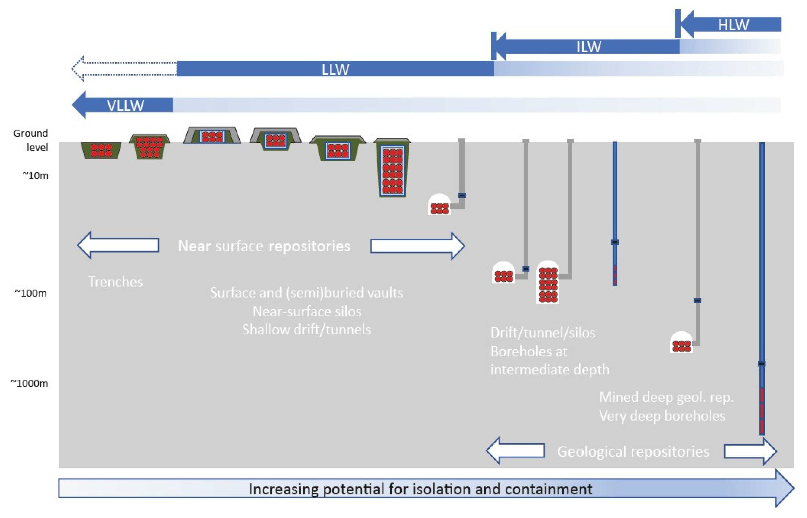
5.1. Graded Approach

Increased levels of hazard, which for nuclear waste are reflected by the activity content and radionuclide half-lives, require increased measures to be taken to isolate the waste from inadvertent human intrusion and to minimise the migration of activity back to the biosphere. Increasing depth of disposal with increasing hazard level of the waste is a key parameter used to achieve the necessary degree of safety (Figure 8).
The depth is one of the important factors that should be considered for the safety of waste disposal along with other factors of not lesser importance, such as the properties of the host rock formation (NBS), the nuclear waste characteristics, the engineered features of the facility (EBS), regulatory constraints, and national policy. Normally, three depths are considered suitable for the disposal [10]:
  • Near surface (shallow);
  • Intermediate;
  • Deep (geological).
A depth of 30 m is typically used to differentiate between near-surface disposal and disposal at intermediate and greater depths, due to the fact that it is the normal residential intrusion zone related to typical drilling and excavation activities, such as tunnelling, quarrying, and mining. Deep facilities are generally considered at depths greater than about 300 m and these are the depths generally associated with geological disposal facilities (repositories). The intermediate depth facilities are thus in the range from about 30 to 300 m below the surface. It should be noted that the term “Geological repositories” on the bottom of Figure 8, reproduced from [11], is controversially covering intermediate depths of about one hundred metres, which contradicts the IAEA definition of geological disposal facilities specifying that they are located underground several hundred metres or more below the surface [6].
In a disposal facility, the combination of EBS and NBS can effectively confine radioactive material until it has naturally decayed to exemption levels, providing sufficient isolation and containment to ensure an adequate level of protection for people and the environment. The depths of 30 and 300 m are indicative and can only serve as examples, because in each specific case the site-specific conditions (parameters of NBS) and the related safety assessment will dictate the actual facility depth and the requirements of the EBS. In the absence of institutional control, a depth of 30 m is nevertheless considered the minimum necessary to achieve waste isolation and should therefore be the minimum depth required for waste that might constitute a security risk as well [10]. Consideration of greater depths and the use of or enhancement of engineered barriers raises the possibility of using intermediate depth and deep geological repositories.

5.2. Disposal Options

Disposal facilities could be of a trench type, vaults, tunnels, shafts, boreholes, or mined repositories. The main features of various disposal approaches are given in Table 7.

6. Disposal Practices

6.1. Disposal Examples

The volume of nuclear waste generated within the nuclear industry is orders of magnitude smaller compared with other types generated by non-nuclear practices. An obvious example can be the case of an electrical power plant generating ~1 GW of electricity for a year, which roughly suffices to support a one-million-inhabitant city. A NPP in this case produces ~25 tonnes of SNF and a few hundred cubic metres of LILW to be finally disposed of. Similarly, a coal-powered power station of this capacity generates annually ~6.5 × 10⁶ tonnes of CO2, >300 × 103 tonnes of ash, which typically contains ~400 tonnes of toxic heavy metals including radioactive U and Th, and >5 × 10³ tonnes of noxious gases, which, as a rule, need purification before discharge [22]. The nuclear waste disposal practices account for many years of successful operation and multiple disposal facilities with a global estimate as shown in Table 8 [23].
Many nuclear waste disposal facilities have been constructed and are being operated, including trench disposal for VLLW, e.g., in France, Spain, and Sweden, or for LLW in arid areas, e.g., in Argentina, India, Iran, South Africa, and the US; near-surface engineered facilities for LLW, e.g., in China, the Czech Republic, France, India, Japan, Russia, Slovakia, Spain, the UK, and Ukraine; sub-surface engineered facilities for low- and intermediate-level waste (LILW), e.g., in Sweden and Finland; borehole disposal of LLW in the US; and geological facilities of LILW, e.g., in Germany and the US [23]. Table 9 gives examples of disposal methods and disposal facilities.
In the UK, the Nuclear Decommissioning Authority (NDA) has developed a set of generic GDF concepts appropriate to the geological environments that have not yet been selected although the experiences of GDF in Sweden and Finland are fully accounted for. For some types of nuclear waste, such as SNF, a possible approach is the use of deep and very deep boreholes [22]. The well-advanced GDF in Sweden and Finland aim to dispose of the SNF in a granitic bedrock using copper containers with cast-iron inserts. The container will be placed into vertical holes within horizontal tunnels and will be backfilled with highly compacted bentonite, which swells in contact with water. The copper container is expected to remain un-breached by corrosion for a period in the order of 100,000 years [22].
Germany is planning to dispose of the non-heat-generating nuclear wastes at the former Konrad iron ore mine with past disposal practices at the Asse II and Morsleben sites [7,8]. The disposal of heat-generating wastes was planned within salt (halite) formations with thick carbon steel containers placed in disposal holes or shafts and surrounded by crushed halite. Halite exhibits plastic creep behaviour so that the nuclear waste containers will rapidly be fixed within salt rock. The waste container is expected to remain intact until short-lived radionuclides have decayed to background (exemption) levels. A salt dome at Gorleben was thoroughly investigated with two access shafts being sunk to the depth of a prospective national GDF [22].

6.2. Borehole Disposal Facilities (BDFs)

The borehole-type disposal facilities (BDFs) can effectively provide long-term isolation of nuclear waste in suitable geological horizons [2,3,36,37,38]. Shallow BDFs have been used within many decades in many countries for storage and disposal of radioactive waste including disused sealed radioactive sources (DSRS) [39]. Compared with mined disposal facilities, BDFs have shorter periods of site selection, construction, operation, and closure as well as a lower probability of human intrusion compared to mined shaft-type disposal facilities. The concept of a BDF near the surface or at intermediate depths is supported by the IAEA specifically for the disposal of DSRSs [39]. The interest in BDFs has recently increased in many countries, e.g., the UK, the US, Russia, Sweden, Germany, Israel, Australia, Croatia, Denmark, the Netherlands, Norway, and Slovenia [36,40,41,42,43]. BDFs can be reliable and effective disposal facilities, especially using horizontal drillholes (Figure 9) by utilising the existing drilling technologies [36,44].
The concept of disposal in lateral boreholes combines the technologies of borehole and shaft disposals and the advantages of both borehole and shaft disposal facilities. The multi-layer structure of the sedimentary cover with a thickness of 0.5–1 km can provide a reliable shield against vertical migration of groundwater from the waste placement horizon. The drilling of horizontally oriented boreholes can be performed within very short time periods; therefore, the commissioning of BDFs with horizontal holes can be accomplished in much shorter times compared with mined GDFs.

7. Safety of Nuclear Waste Disposal

Nuclear waste disposal is intended to isolate the waste both from human activity and from natural dynamic processes. As a rule, the impacts of disposal facilities are assessed in terms of the most probable doses caused by potentially released and migrating radionuclides. Following the recommendations of ICRP [12], expositions due to natural processes are typically taken as <0.3 mSv/y and the expositions due to human intrusion < 10 mSv/y. If the assessed doses are >10 mSv/y, the design of the repository is reconsidered; moreover, if assessed doses are above 100 mSv/y, the design of the repository needs to be reconsidered [12]. The adequacy of the safety of a system is proved by the safety analysis report (SAR).
The SAR of a nuclear waste disposal facility evaluates the performance of the facility and its radiological impacts to the environment and humans and results in data demonstrating compliance with safety standards. Otherwise, it shows the unacceptability of the proposed concept. The main emphasis of SAR is generally on radiological criteria, including:
  • Limited doses or risks (relative).
  • Levels of radiological protection to future generations provided at the same level as at present.
  • Ensuring that the additive impact of the disposal is limited.
Figure 10 illustrates the typical results of such type calculations within SARs (see the details within reference [45]).
It can be noted that doses from the nuclear waste disposal sites are theoretically detectable with a delay of a thousand years although they are expected only at an almost negligible level compared to background radiation. Indeed, the background radiation levels vary within 1000 to 10,000 μSv/y [23] while national regulatory organisations set typical exposure limits from the disposal sites around the level of 300 μSv/y. Moreover, the background radiation due to both the cosmic and surrounding natural radionuclides components is never at a constant level, instead being characterised by both short- and long-time variations within many tens % around the average level. Archaeological analogues show that one can count on the EBS of disposal facilities within periods of several hundred –one thousand years whereas the radiological impacts of deep uranium ore bodies confirm a very limited concern over periods of many hundreds of thousands and millions of years [46].
The most difficult task for SARs is the case of GDFs, which are the only solution for HLW. Uncertainties over extended geological time scales are the most challenging SAR issues and the appearing novel research works add questions on limitations to wasteform materials [47] and the ranges of the prediction models used [22]. The HLW disposal issue is expected to become less challenging with time when advanced fuel cycles start operating [48]. This is because the Generation IV reactors, in addition to a more effective nuclear energy utilisation, can also decrease the nuclear waste radiotoxicity, mainly by transmutation of MAs during their operation [48,49,50].

8. Conclusions

Nuclear waste disposal is the final step—end point—of NWM, aiming to permanently place the radioactive waste in a dedicated disposal facility. The multi-barrier approach to the disposal of nuclear waste envisages utilisation within disposal facilities, a combination of both EBS and NBS that effectively confines radionuclides and ensures an adequate level of protection for people and the environment. Disposal of nuclear waste is a well-established practice, mostly for LLW and to a lesser extent for ILW, with many disposal facilities being successfully operated for many decades. These demonstrate an excellent performance with minimal environmental impact, as expected through the modelling approaches used. The most challenging is the case of HLW disposal into GDFs although several countries (e.g., Finland, Sweden) are currently very close to starting to operate GDFs, which shall mark an important step forward to the safe, peaceful use of nuclear energy. Along with the Waste Isolation Pilot Plant (WIPP), which has been disposing of legacy transuranic (TRU) waste since 1999 in the US, these will add confidence in the issues of deep geological disposal.

Author Contributions

Conceptualisation, M.I.O. and H.J.S.; methodology, M.I.O.; validation, H.J.S.; writing—original draft preparation, M.I.O.; writing—review and editing, M.I.O. and H.J.S.; All authors have read and agreed to the published version of the manuscript.

Funding

This research received no external funding.

Data Availability Statement

Not applicable.

Acknowledgments

Authors are thankful for fruitful discussions to Neil Chapman, Ian McKinley, Carol Jantzen, Rodney Ewing, B.P. McGrail, Vladislav Petrov, Ferus Gibb, Ian Donald, Boris Burakov, Ramesh Dayal, Valery Efremenkov, Zoran Drace, Peter Ormai, Andrey Guskov, Felicia Dragolici. Authors wish also to thank to anonymous reviewers for their comments and recommendations..

Conflicts of Interest

The authors declare no conflict of interest.

References

  1. IAEA. Radiation Protection and Safety of Radiation Sources: International Basic Safety Standards; IAEA Safety Standards Series GSR Part 3; IAEA: Vienna, Austria, 2014. [Google Scholar]
  2. IAEA. Scientific and Technical Basis for Near-surface Disposal of Low and Intermediate Level Waste; TRS-412; IAEA: Vienna, Austria, 2003. [Google Scholar]
  3. IAEA. Scientific and Technical Basis for Geological Disposal of Radioactive Wastes; TRS-413; IAEA: Vienna, Austria, 2003. [Google Scholar]
  4. Crossland, I. Disposal of radioactive waste. In Nuclear Fuel Cycle Science and Engineering; Woodhead Publishing Series in Energy; Woodhead Publishing: Sawston, UK, 2012; Chapter 18; pp. 531–557. [Google Scholar] [CrossRef]
  5. Ahn, J.; Apted, M.J. Geological Repository Systems for Safe Disposal of Spent Nuclear Fuels and Radioactive Waste, 2nd ed.; Elsevier: Woodhead/Cambridge, UK, 2017; 778p. [Google Scholar]
  6. IAEA. IAEA Nuclear Safety and Security Glossary; IAEA: Vienna, Austria, 2022. [Google Scholar]
  7. Rohlig, K.-J. Disposal and other conceivable strategy ‘endpoints’ for different types of waste. In Nuclear Waste: Management, Disposal and Governance; Rohlig, K.-J., Ed.; IOP Publishing Ltd: Bristol, UK, 2022; Chapter 7; pp. 7.1–7.19. [Google Scholar] [CrossRef]
  8. Rohlig, K.-J. Geologic (‘deep’) disposal of high-level and other long-lived waste: Host rocks, concepts, current international status. In Nuclear Waste: Management, Disposal and Governance; IOP Publishing Ltd: Bristol, UK, 2022; Chapter 8; pp. 8.1–8.25. [Google Scholar] [CrossRef]
  9. IAEA. Disposal of Radioactive Waste Specific Safety Requirements; IAEA Safety Standards Series No. SSR-5; IAEA: Vienna, Austria, 2011; Available online: https://www-pub.iaea.org/MTCD/Publications/PDF/Pub1449_web.pdf (accessed on 19 September 2022).
  10. IAEA. Selection of Technical Solutions for the Management of Radioactive Waste; TECDOC-1817; IAEA: Vienna, Austria, 2017. [Google Scholar]
  11. IAEA. Design Principles and Approaches for Radioactive Waste Repositories; NW-T-1.27; IAEA: Vienna, Austria, 2020. [Google Scholar]
  12. ICRP. Protection of the Public in Situations of Prolonged Radiation Exposure; Publication 82; Annals of the ICRP Vol. 29, Nos 1-2; Pergamon Press: Oxford, UK; New York, NY, USA, 1999. [Google Scholar]
  13. IAEA. Policies and Strategies for Radioactive Waste Management; IAEA Nuclear Energy Series, NW-G-1.1; IAEA: Vienna, Austria, 2009; 68p, Available online: http://www.pub.iaea.org/MTCD/publications/PDF/Pub1396_web.pdf (accessed on 19 September 2022).
  14. IAEA. Fundamental Safety Principles; IAEA Safety Standards Series No. SF-1; IAEA: Vienna, Austria, 2006. [Google Scholar]
  15. Metcalf, P.; Batandjieva, B. International safety standards for radioactive waste (RAW) management and remediation of contaminated sites. In Radioactive Waste Management and Contaminated Site Clean-up: Processes, Technologies and International Experience; Lee, W.E., Ojovan, M.I., Jantzen, C.M., Eds.; Woodhead Publishing Series in Energy No. 48; Woodhead Publishing: Cambridge, UK, 2013; Chapter 3; pp. 73–114. ISBN 0 85709 435 1. [Google Scholar]
  16. IAEA. Classification of Radioactive Waste; General Safety Guide GSG-1; IAEA: Vienna, Austria, 2009. [Google Scholar]
  17. IAEA. Joint Convention on the Safety of Spent Fuel Management and on the Safety of Radioactive Waste Management; IAEA: Vienna, Austria, 2006; Available online: http://www-ns.iaea.org/conventions/waste-jointconvention.asp (accessed on 18 August 2022).
  18. DEFRA. Policy for the Long Term Management of Solid Low Level Radioactive Waste in the United Kingdom; Department for Environment, Food and Rural Affairs: London, UK, 2007. [Google Scholar]
  19. Germany. Joint Convention on the Safety of Spent Fuel Management and on the Safety of Radioactive Waste Management Report of the Federal Republic of Germany for the Fourth Review Meeting. Report prepared by Federal Ministry for the Environment, Nature Conservation and Nuclear Safety (BMU), August 2011. Available online: http://www.bmu.de/files/english/pdf/application/pdf/jc_4_bericht_deutschland_en.pdf (accessed on 18 August 2022).
  20. Cohen, B.L. High-level radioactive waste from light-water reactors. Rev. Mod. Phys. 1977, 49, 1–20. [Google Scholar] [CrossRef]
  21. Koplik, C.M.; Kaplan, M.F.; Ross, B. The safety of repositories for radioactive wastes. Rev. Mod. Phys. 1982, 54, 269–312. [Google Scholar] [CrossRef]
  22. Chapman, N.; Hooper, A. The disposal of radioactive wastes underground. Proc. Geol. Assoc. 2012, 123, 46–63. [Google Scholar] [CrossRef]
  23. Ojovan, M.I.; Lee, W.E.; Kalmykov, S.N. An Introduction to Nuclear Waste Immobilisation, 3rd ed.; Elsevier: Amsterdam, The Netherlands, 2019; 497p. [Google Scholar]
  24. IAEA. Implications of Partitioning and Transmutation in Radioactive Waste Management; IAEA: Vienna, Austria, 2004; p. 127. [Google Scholar]
  25. Westlen, D. Reducing radiotoxiciti in the long run. Progr. Nucl. Energy 2007, 49, 597–605. [Google Scholar] [CrossRef]
  26. NEA. Potential Benefits and Impacts of Advanced Nuclear Fuel Cycles with Actinide Partitioning and Transmutation; Rep. 6894; NEA OECD: Paris, France, 2011; 73p. [Google Scholar]
  27. Ojovan, M.I.; Lee, W.E.; Barinov, A.S.; Startceva, I.V.; Bacon, D.H.; McGrail, B.P.; Vienna, J.D. Corrosion of low level vitrified radioactive waste in a loamy soil. Glass Technol. Eur. J. Glass Sci. Technol. A 2006, 47, 48–55. [Google Scholar] [CrossRef] [Green Version]
  28. Kashcheev, V.A.; Logunov, M.V.; Shadrin, A.Y.; Rykunova, A.A.; Schmidt, O.V. Strategy for the fractionation of HLW from SNF reprocessing. Radioact. Waste 2022, 2, 6–16. [Google Scholar] [CrossRef]
  29. OECD. Features, Events and Processes (FEPs) for Geologic Disposal of Radioactive Waste; An International Database; OECD: Paris, France, 2000. [Google Scholar]
  30. Hyatt, N.C.; Ojovan, M.I. Special Issue: Materials for Nuclear Waste Immobilization. Materials 2019, 12, 3611. [Google Scholar] [CrossRef]
  31. National Research Council. Waste Forms Technology and Performance: Final Report; National Academies Press: Washington, DC, USA, 2011; p. 308. [Google Scholar]
  32. OECD. Engineered Barrier Systems and the Safety of Deep Geological Repositories; Report EUR 19964 EN.; OECD: Issy-Ies-Moulineaux, France, 2003. [Google Scholar]
  33. Frankel, G.S.; Vienna, J.D.; Lian, J.; Scully, J.R.; Gin, S.; Ryan, J.V.; Wang, J.; Kim, S.H.; Windl, W.; Du, J. A comparative review of the aqueous corrosion of glasses, crystalline ceramics, and metals. NPJ Mater. Degrad. 2018, 2, 15. [Google Scholar] [CrossRef]
  34. Barinov, A.S.; Ojovan, M.I.; Ojovan, N.V. Corrosion of carbon steel containers during open site tests of vitrified radioactive waste. Mat. Res. Soc. Symp. Proc. 1998, 506, 971–972. [Google Scholar] [CrossRef]
  35. Ojovan, M.I.; Hand, R.J.; Ojovan, N.V.; Lee, W.E. Corrosion of alkali-borosilicate waste glass K-26 in non-saturated conditions. J. Nucl. Mat. 2004, 340, 12–24. [Google Scholar] [CrossRef]
  36. Kochkin, B.; Malkovsky, V.; Yudintsev, S.; Petrov, V.; Ojovan, M. Problems and perspectives of borehole disposal of radioactive waste. Prog. Nucl. Energy 2021, 139, 103867. [Google Scholar] [CrossRef]
  37. Chapman, N.A. Who Might Be Interested in a Deep Borehole Disposal Facility for Their Radioactive Waste? Energies 2019, 12, 1542. [Google Scholar] [CrossRef] [Green Version]
  38. Freeze, G.A.; Stein, E.; Brady, P.V.; Lopez, C.; Sassani, D.; Travis, K.; Gibb, F.; Beswick, J. Deep borehole safety case. Energies 2019, 12, 2141. [Google Scholar] [CrossRef] [Green Version]
  39. IAEA. Management of Disused Sealed Radioactive Sources; IAEA Nuclear Energy Series No. NW-T-1.3; IAEA: Vienna, Austria, 2014. [Google Scholar]
  40. Deep Isolation. Preliminary Assessment of a Deep Isolation Borehole Repository as a Disposal Option for Nuclear Waste in the ERDO Countries; Deep Isolation: Berkeley, CA, USA, 2021; 36p, Available online: https://www.norskdekommisjonering.no/wp-content/uploads/2021/12/Preliminary-assessment_Deep-Isolation-borehole-repository-as-a-disposal-option-for-nuclear-waste-in-the-ERDO-countries.pdf (accessed on 18 August 2022).
  41. Bracke, G.; Kudla, W.; Rosenzweig, T. Status of Deep Borehole Disposal of High-Level Radioactive Waste in Germany. Energies 2019, 12, 2580. [Google Scholar] [CrossRef] [Green Version]
  42. Freeze, G.; Sassani, D.; David, O.K.-B.; Calvo, R.; Peer, G. Borehole Disposal of Radioactive Waste in Israel–20388. In Proceedings of the WM2020 Conference, Phoenix, AZ, USA, 8–12 March 2020. [Google Scholar]
  43. Mallants, D.; Sander, R.; Avijegon, A.; Engelhardt, H.-J. Cost Analysis of Deep Large-diameter Drill Holes–21048. In Proceedings of the WM2021 Conference, Phoenix, AZ, USA, 8–12 March 2020. [Google Scholar]
  44. Muller, R.A.; Finsterle, S.; Grimsich, J.; Baltzer, R.; Muller, E.A.; Rector, J.W.; Payer, J.; Apps, J. Disposal of High-Level Nuclear Waste in Deep Horizontal Drillholes. Energies 2019, 12, 2052. [Google Scholar] [CrossRef] [Green Version]
  45. Ojovan, M.I.; Guskov, A.V.; Prozorov, L.B.; Arustamov, A.E.; Poluektov, P.P.; Serebriakov, B.E. Safety assessment of bore-hole repositories for sealed radiation sources disposal. MRS Online Proc. Libr. 1999, 608, 141–146. [Google Scholar] [CrossRef]
  46. Chapman, N.; Dansie, A.; McCombie, C. Artifact to analogue: Archeology of arid environments points to management options for Yucca Mountain. Radwaste Solut. 2007, 14, 22–31. [Google Scholar]
  47. Ojovan, M.I. Challenges in the Long-Term Behaviour of Highly Radioactive Materials. Sustainability 2022, 14, 2445. [Google Scholar] [CrossRef]
  48. Pershukov, V.; Artisyuk, V.; Kashirsky, A. Paving the Way to Green Status for Nuclear Power. Sustainability 2022, 14, 9339. [Google Scholar] [CrossRef]
  49. Chersola, D.; Lomonaco, G.; Marotta, R. The VHTR and GFR and their use in innovative symbiotic fuel cycles. Prog. Nucl. Energy 2015, 83, 443–459. [Google Scholar] [CrossRef]
  50. Harvego, E.A.; Schultz, R.R. Generation IV Technologies. In Nuclear Engineering Handbook; Kok, K.D., Ed.; CRC Press, Taylor & Francis Group: Boca Raton, FL, USA, 2009; pp. 227–242. [Google Scholar]
Figure 1. Schematic of nuclear waste management (NWM) administrative (a) and operational (b) activities. The operational activities are sub-divided into pre-disposal and disposal activities.
Energies 15 07804 g001
Figure 2. Schematic of IAEA radioactive waste classification scheme. The term “activity content” covers activity concentration and total activity. Reproduced with permission of the IAEA from [16].
Energies 15 07804 g002
Figure 3. Logic diagram illustrating the use of the IAEA classification scheme to assist in determining disposal options. Reproduced with permission of the IAEA from [16].
Energies 15 07804 g003
Figure 4. Schematic of nuclear waste classification of Germany.
Energies 15 07804 g004
Figure 5. The relative toxicity index (RTI) of spent nuclear fuel (SNF) and high-level radioactive waste (HLW). Reproduced with permission of Elsevier from [22].
Energies 15 07804 g005
Figure 6. Schematic of multi-barrier system in nuclear waste disposal: (a) the two main barrier systems—engineered barrier system (EBS) and natural geological barrier (NGB); (b) the UK Nuclear Decommissioning Authority (NDA) example (courtesy of NDA, Moor Row, England, UK). Reproduced with permission of the IAEA from [11].
Energies 15 07804 g006
Figure 7. Estimates of corrosion rates of glasses, ceramics, and metal alloys depicting the initial (r0) and steady state (rr) rates. Reproduced from open access reference [33], courtesy of John Vienna, PNNL.
Energies 15 07804 g007
Figure 8. Illustration of graded approach in selection of nuclear waste disposal depth. Reproduced with permission of the IAEA from [11].
Energies 15 07804 g008
Figure 9. Scheme of disused sealed radioactive sources (DSRS), high-level radioactive waste (HLW), and spent nuclear fuel (SNF) disposal in branching lateral drillholes within suitable geological horizons. Reprinted from with permission of Elsevier from [36].
Energies 15 07804 g009
Figure 10. Typical safety analysis report (SAR) results of expected doses: (a) Expected concentration of radionuclides (Ci/m3) after 100 years for an infiltrating stream flowing through a disused sealed radioactive source’s (DSRS) borehole disposal facility; (b) Expected doses to population Dexp from a hypothetical geological disposal facility (GDF).
Energies 15 07804 g010
Table 1. Classification of radioactive waste in the UK.
Waste ClassParameters
VLLW, low volumeWastes that can be disposed of with ordinary refuse, each 0.1 m3 of material containing less than 400 kBq of beta/gamma activity and is mostly comprised of small volumes from hospitals and universities. For carbon-14 and tritium-containing wastes, the activity limit is 4000 kBq for each 0.1 m3 in total.
VLLW, high volumeRadioactive waste with an upper limit of 4 MBq per tonne (not including tritium) that can be disposed of at specified landfill sites. For tritium-containing wastes, the upper limit is 40 MBq per tonne.
LLWWastes containing radioactive materials other than those suitable for disposal with ordinary refuse, but not exceeding 4 GBq per tonne of alpha or 12 GBq per tonne of beta/gamma activity.
ILWWastes with radioactivity levels exceeding the upper boundaries for LLW that do not need heating to be taken into account in the design of storage or disposal facilities.
HLWWastes in which the temperature may rise significantly as a result of their radioactivity, so this factor has to be taken into account in designing storage or disposal facilities.
Table 2. Examples of typical retention times for LLW and SNF.
Nuclear Waste StreamTypical Radioactive Contaminant (Half-Life, y)Typical Contents, Bq/g Clearance Level CL, Bq/g Typical Retention Time 1, y
LLW (vitrified)137Cs (30.17)3.73 × 10³ [27]0.1 [1]457
SNF (burnup 50 GW d/t U)237Np (2.1 106)1.35 × 10⁶ [28]1 [1]42.7 106
1 Note that the retention time is longer that simply 10 half-lives of decaying radionuclides, which would be only 302 and 21 106 years, correspondingly.
Table 3. Expected time frames of FEPs in years.
FEPTime Frame, y
Decay of SNF radionuclidesMillions
Climate cycles (glaciations)Tens of thousands
Passive institutional control (markers)Thousands
Decay of ILW radionuclidesThousands
Active institutional controlHundreds
Decay of LLW radionuclidesHundreds
Table 4. Engineered barrier systems (EBS) components of actual or planned geological disposal/storage facilities.
CountryWasteWasteformContainerBackfill
BelgiumHLWGlassStainless steelClay, Bentonite, Quartz sand, Graphite
SNFSNFSteel
CanadaSNFSNFCarbon steel, CopperBentonite, Sand, Clay, Crashed rock
ChinaHLWGlassStainless steelBentonite
Czech RepublicILWConcreteSteelBentonite
HLWGlass
SNFSNF
FinlandSNFSNFCopper, IronBentonite, Crushed host rock
FranceILWVariousStainless steel, ConcreteConcrete lining
HLWGlassStainless steel, SteelBentonite
SNFSNFStainless steelBentonite, Disposal tube
Germany 1LILWNot considered as EBSNot considered as EBSSalt concrete
JapanHLWGlassCarbon steelBentonite, Sand
KoreaSNFSNFSteel, Copper,Bentonite, Sand
RussiaHLWGlassSteel, Stainless steelBentonite, Concrete
SpainSNFSNFCarbon steelBentonite
SwedenSNFSNFCopper, IronBentonite
SwitzerlandHLWGlassSteelBentonite
UKLILWCementSteel, ConcreteCement based
USTRU 2/WIPP 3VariousSteelMgO
SNF/YMP 4SNFStainless steel, Ni-based alloy-
HLW/YMPGlassStainless steel-
1 Morsleben; 2 Transuranic waste; 3 Waste Isolation Pilot Plant,; 4 Yucca Mountain Plant (Nevada). SNF disposal at the YMP was halted during the Obama administration with Blue Ribbon Commission assigned and tasked with the development of a perspective for the NWM in the US.
Table 5. Functions of the wasteform (immobilising matrix) and container components of EBS.
CountryWasteformContainer
Belgium10,000 y resistance to leachingFacilitate handling
Canada10,000 y radionuclide retention100,000 y containment
Czech Republic10,000 y radionuclide retention500–1000 y containment
FinlandSlow rate of release100,000 y containment
France100,000 y resistanceFacilitate handling
Germany 1Not part of EBSNot part of EBS
Japan>10,000 y containment and slow release1000 y containment, creating reducing conditions
KoreaResistance to leaching1000 y containment
SpainSlow rate of release1000 y containment
Sweden (KBS-3)Slow rate of release100,000 y isolation
Switzerland150,000 y low releaseInitial period complete containment
UK (Nirex, RWM)300–500 y limit release300–500 y physical integrity, limit release
USWIPP: Not part of EBS; YMP: reduce release rateWIPP: Not part of EBS; YMP: >10,000 y resistance to corrosion
1 Morsleben.
Table 6. Geological formations for deep underground disposal of nuclear waste (GDF).
Host Rock Rock CharacteristicsRadionuclide Transport Mechanisms Country
Granite, gneissFractured, groundwater flow in open fractures.Advection and diffusionCanada, China, Finland, Russia, Sweden, UK.
Salt bedded, domeNo open fractures, no groundwater.DiffusionGermany, USA (WIPP)
Volcanic tuffs and lavasFractures and pores, unsaturated.Percolating waterUSA (Yucca Mountain). UK (Longlands Farm)
Clays and mudrocks consolidated, plasticNo open fractures, stagnant pore water.DiffusionBelgium, China, Hungary, France, Russia, Switzerland
Table 7. Nuclear waste disposal options. Reproduced with permission of the IAEA from [10].
Disposal MethodFeaturesLimitationsWaste Subject to Disposal
Landfill sites used for domestic and industrial wastesSimple and easy to construct and operate
No institutional control for disposed wastes
Existing facilities can be used
Poor containment and isolationExempt waste
VLLW
Near-surface facilitiesSimple near-surface facilities (trenches)Excavated trenches covered with a layer of soil
Simple and inexpensive
Used historically for short-lived LLW
Activity concentration limits should be established
Erosion, intrusion, and percolation of rainwater may affect the performance
Decay to negligible levels during institutional control period (e.g., 100–300 years) is required
Risk of fast migration of radionuclides to biosphere
Waste containing radionuclides with very short half-lives (VSLW), e.g., those often used for research and medical purposes
Engineered near-surface facilitiesMulti-barrier approach to enhance the safety of disposal
Engineered vault repositories
Long experience with operationEase of waste emplacement and increased efficiency in the management and closure of the repository
Institutional control (e.g., 100–300 years) is required
Erosion, intrusion, and percolation of rainwater may affect the performance
LLW with short-lived radionuclides at higher levels of activity concentration, and also long-lived radionuclides, but only at relatively low levels of activity concentration.
Near-surface borehole or shaft facilitiesAlternative or complementary to near-surface vaults.Economical option and also minimises the probability of human intrusionSize and quantity of waste packages is limitedInstitutional control for up to, e.g., 300 years is requiredDSRS 1
Intermediate-depth facilitiesIntermediate-depth shafts or boreholes without EBSAttractive disposal option for small volumes of waste such as radioactive sources
The depth is adequate to eliminate the risk of erosion, intrusion, and percolation of rainwater
Flexibility in design
Possibility to use existing disused cavities (e.g., mines)
Limited or no contact between percolating water is required
Applicable in very low permeability host rocks, with little or no advection of groundwater
Good backfilling and sealing are required
Extensive characterisation of the site required
Disused sealed radiation sources such as 90Sr, 137Cs, 238Pu, and 241Am
Intermediate-depth shafts or boreholes with EBSsAttractive disposal option for small volumes of waste such as radioactive sourcesSignificant water inflow or the geotechnical characteristics of the geological materials is allowed
Waste containers and packages are important elements in the EBS
Disused high-activity sealed sources
Intermediate-depth repositoriesMassive concrete vaults or silos, with additional EBSs such as clay backfills and buffersHigh cost
Extensive characterisation of the site required
ILW—waste that will not decay sufficiently within the period of institutional control
Deep facilitiesDeep boreholes without EBSsContainment of radionuclides is provided by the geological barrier
No requirement for supplementary EBSs
Lower flow, more stable chemistry and longer potential return paths to the biosphere
High costLimited volumes of disposed wasteDisused high-activity and long-half-life radioactive sources
Deep boreholes with EBSsContainment of radionuclides is provided by the geological barrier
Use of higher flow environments encountered in more permeable geological formations is possible.
High cost
Limited volumes of disposed waste
Disused high-activity and long-half-life radioactive sources
Mined geological repositoriesMay comprise caverns or tunnels with varying types of EBSsContainment of radionuclides is provided by the geological barrier
Suitable for all waste categoriesEnhanced confinement
No operational experience for HLW and SFWHigh capital cost
Assurance of site integrity for above 10,000 years is required
Extensive safety and performance analyses required
Suitable geological media required
High-level vitrified waste and encapsulated spent fuelLong-lived LILW
Disused sources of any activity and half-life
1 Disused sealed radioactive source.
Table 8. Global estimate inventory for 2014 of radioactive waste disposed of.
Waste ClassCumulative Disposal, m3
VLLW273,000
LLW65,192,000
ILW10,589,000
HLW72,000 1
1 Disposal via deep injection of aqueous waste reported by the Russian Federation and temporary disposal of solid HLW in Ukraine.
Table 9. Nuclear waste disposal methods and operating or planned disposal facilities.
Disposal MethodCountryFacilityWaste
NSDF (trench)FranceCIRES, MorvilliersVLLW
SpainEl Cabril Disposal FacilityVLLW
NSDF (engineered)FranceCSA, department of AubeShort-lived LILW
CSM, near La HagueShort-lived LILW
Czech RepublicDukovany RepositoryLLW
Richard Repository near LitoměřiceLLW
RussiaFSUE RADON near Sergiev PosadShort-lived LILW, DSRS
SlovakiaNational Radioactive Waste Repository MochovceLLW
SpainEl Cabril Disposal FacilityVLLW, LLW, ILW, DSRS
UKLLW Repository at Drigg, CumbriaLLW
Intermediate depthsRomaniaNational Repository Baiţa-BihorLILW
FinlandLoviisa VLJ RepositoryLILW
Olkiluoto VLJ RepositoryLILW
SwedenSFR ForsmarkLILW
GDFUSWIPPTransuranic (TRU) waste
Yucca MountainHLW, SNF
SwedenForsmark siteSNF
FinlandOlkiluoto siteSNF
FranceBure siteHLW, SNF, Long-lived ILW
ChinaXinchang site in the Beishan areaHLW, SNF
RussiaYeniseiskiy site in the Krasnoyarsk KraiHLW, SNF
GermanyAsse II (former salt and potassium mine, past practice, waste to be retrieved)Waste with negligible heat generation
ERAM (Morsleben) (former salt and potassium mine, past practice, facility to be closed)Waste with negligible heat generation
Konrad (former iron ore mine, under construction including new emplacement vaults)Waste with negligible heat generation
Publisher’s Note: MDPI stays neutral with regard to jurisdictional claims in published maps and institutional affiliations.

