Article

Numerical Study of Heat Transfer Enhancement by Arc-Shaped Fins in a Shell-Tube Thermal Energy Storage Unit

1
School of Energy and Power Engineering, Northeast Electric Power University, Jilin 132012, China
2
School of Automation Engineering, Northeast Electric Power University, Jilin 132012, China
*
Author to whom correspondence should be addressed.
Energies 2022, 15(20), 7799; https://doi.org/10.3390/en15207799
Submission received: 14 September 2022 / Revised: 5 October 2022 / Accepted: 17 October 2022 / Published: 21 October 2022
(This article belongs to the Section D: Energy Storage and Application)

Abstract

:
Latent heat thermal energy storage (LHTES) technology can alleviate the mismatch between the supply and demand of solar energy and industrial waste heat, but the low thermal conductivity of phase change materials (PCMs) is an issue that needs to be solved. In this work, the effects of the bifurcated fins on melting and solidification are studied, and local and global entropy generation are discussed. The radial lag time and the circumferential lag time were defined to evaluate thermal penetration and thermal uniformity. Subsequently, a novel arc-shaped fin configuration was proposed to further enhance the heat transfer. The results showed that attaching the bifurcated fins could effectively reduce the global entropy generation. Increasing the trunk fin length was beneficial to enhance the thermal uniformity and promote the melting process, while increasing the branch fin was more effective in the solidification process. Overall, thermal uniformity determined the phase change process. More importantly, the concentric arc-shaped fins significantly reduced the heat transfer hysteresis region, showed better thermal performance than straights fins, and the energy storage and release time were reduced by 52.7% and 51.6%, respectively.

1. Introduction

In recent years, serious environmental problems have been caused by the use of fossil energy. Therefore, effective utilization of solar energy and industrial waste heat has become the focus of current research. Based on the challenges mentioned above, latent heat thermal energy storage (LHTES) systems have received a great deal of attention as an effective means of storing thermal energy. Phase change materials (PCMs) are widely used in energy [1,2,3], thermal management [4,5,6] and buildings [7,8] due to their huge latent heat in phase change process. However, the low thermal conductivity of PCMs severely limits the energy storage and release rate of LHTES systems. To overcome this drawback, many methods are employed to accelerate the heat storage and release processes of LHTES unit such as fins, nano-PCM [9,10,11], metal foams [12,13] and carbon-based composite PCMs [14,15]. Among them, attaching fins is the most popular method due to their simplicity and inexpensiveness [16,17,18].
Many studies have been carried out on fins to enhance heat transfer in LHTES units, including conventional straight fins and bifurcated fins. For conventional fins, most researches had conducted studies on fin parameters such as fin length [19], number [20] and location [21]. Abidi [22] studied the PCM melting and solidification process in a shell-tube LHTES units. The temperature gradient in the radial and angular directions was analyzed. The results showed that the fins could effectively accelerate the energy storage and release process. Mohammad Javad Zarei [23] numerically studied the structure and size of fins to revel the optimal design of the LHTES unit to minimize the energy release time and achieve the best performance improvement. The results showed that the performance of the fin with an angle of 90° and a length and width of 28 mm and 1 mm, respectively, was the best. Compared with a system without fins, the fin configuration could reduce the solidification time by 42%. In addition, increasing the fin length had a positive effect on improving the performance of the LHTES system. Kunal Bhagat [24] used a combination of numerical model and enthalpy change technology to study the flow and heat transfer behavior in an LHTES unit. The effects of fin number, thickness and height on the melting process were revealed deeply. The results showed that the fin number and fin thickness had a significant impact on the heat transfer performance of the LHTES system, and the heat transfer enhancement effect of the high heat conductivity fins was obvious. Al-Abidi [25] studied the energy release process in a shell-tube LHTES unit. Two cases of pure conduction and natural convection were considered in the simulation. Various design parameters were considered, such as fin number, length and thickness. The results showed that the optimized fin structure shortened the discharge process by 35%.
On the basis of regular fins, researchers designed novel bifurcated fins [26] to expand the heat transfer area in limited space. The fins were designed as a combination of trunk fins and branch fins, and the enhancement heat transfer of the bifurcated fins was well studied. M. Alizadeh [27] studied the energy release process of water in an LHTES unit and designed V-shaped fins to promote solidification. The response surface method was used to explore the effect of fin parameters. The results showed that the V-shaped fins had a better promotion effect on the solidification. Al-Mudhafar [28] used T-shaped fins as innovative fins to accelerate the energy storage process of PCM in an LHTES unit. The three-way fin was compared with the traditional fin shape, and the thermal performance of the three-way fin was evaluated. The total energy storage time of PCM using T-shaped fins was reduced by 33% compared with the longitudinal fins. The geometry of the fin had an important influence on the melting of the PCM. A Sciacovelli [29] used tree-shaped fins to improve the performance of the shell-tube LHTES unit. The geometry of tree-shaped fins with one branch and two branches was optimized. The results showed that the efficiency of system was increased by 24% by tree-shaped fins. K.H. Hosseinzadeh [30] studied the energy release process of nano-PCM with tree-like branch fins in an LHTES system. The effect of fin angle on the solidification process was studied. The results showed that with the increase in the fin bifurcation angle, the temperature and total energy of the system decreased, and the solid fraction increased. Chengbin Zhang [31] compared the temperature distribution, liquid-solid interface and liquid fraction between the tree-shaped fins and radial fins. The results showed that the tree-shaped fins significantly improved the energy release performance of the shell-tube LHTES unit. The tree-shaped-fin LHTES device had a shorter release period, a higher energy release rate and stronger temperature uniformity.
After a detailed literature review, it can be found that some researchers carried out studies on the energy storage or release process of LHTES unit with bifurcated fins. However, in the authors’ previous study, melting and solidification exhibit reversed liquid–solid interface evolution, which gives the LHTES unit different heat transfer hysteresis zones during the phase change process, and this issue is not well solved with the conventional straight bifurcated fins. Therefore, it is particularly important to consider both the storage and release processes, promote space optimization and reduce the heat transfer hysteresis zones of the LHTES unit. In response to these problems, in this paper, the different effects of trunk fins and branch fins on melting and solidification are firstly analyzed. Considering the different heat transfer hysteresis zones between melting and solidification, a combination of arc-shaped fins and bifurcated fins was proposed to improve the local heat transfer and reduce the heat transfer hysteresis region of LHTES unit. The effects of arc-shaped fin structure on thermal penetration, thermal uniformity and global and local entropy are well discussed. The comprehensive analysis of thermal performance and entropy generation provide guidance for understanding phase transition characteristics and more efficient operation performance of LHTES systems.

2. Problem Definition and Modeling

2.1. Problem Definition

Figure 1 shows the model of the LHTES unit with aluminum bifurcated fins, which have an aluminum inner tube with radius (Ri) of 40 mm and thickness of 2 mm, an insulated outer shell with radius (Ro) of 120 mm and thickness of 2 mm. Two branch fins are arranged on the trunk fin. The lengths of the branch fins are L1 and L2, and the distances between the two branch fins are P1 and P2, and P1 = P2. H1 is the distance between the outer edge of the fin and the shell. In addition, as shown in Figure 1b, radial monitoring points 1 to 4 and circumferential monitoring points 5 to 11 are marked to evaluate the thermal penetration and thermal uniformity in the LHTES unit, respectively. What is more, paraffin (RT50) [32] is selected to study the phase transition process, and all thermal parameters are listed in Table 1.

2.2. Mathematical Modeling

In this work, the commercial CFD package Fluent was used in the present analysis. The enthalpy–porosity approach [33,34] is used to solve the solid–liquid interface and temperature distribution during phase transition. The liquid phase fraction indicates the state of the PCM. When the temperature is above the melting point, the liquid fraction is as follows. 1. When the temperature is below the melting point, the liquid fraction is 0. Moreover, the following assumptions are made for the phase transition process:
  • The PCMs is pure.
  • The liquid phase of the PCMs is a Newtonian fluid.
  • The flow in liquid is two-dimensional, laminar and incompressible.
  • The volume changes when phase transition is negligible.
In addition, the governing equations are shown below:
Continuity equation
t ρ + ( ρ u ) = 0
Momentum equation
t ( ρ u ) + ( ρ u u ) = μ 2 u p + ρ g β ( T T r e f ) + S
Energy equation
t ( ρ H ) + ( ρ u H ) = ( k T )
where ρ is the density, u is the velocity vector, H is the enthalpy, P is the pressure and μ is the viscosity. The total enthalpy is:
H = h + Δ H
where the sensible enthalpy h is:
h = h r e f + T r e f T c p Δ T
where href is the reference enthalpy at temperature tref, and cp is the special heat. The latent enthalpy ΔH is expressed as:
Δ H = γ L h
The source term in the momentum equation is:
S = A m u s h ( 1 γ ) 2 γ 3 + ε u
Amush is the mushy region constant. In this work, Amush is set to 105. ε is a small value and takes 0.0001 to prevent the division by zero. γ represents the liquid fraction and is defined as:
γ = { 0 if   T < T s T T s T l T s if   T s < T < T l 1 if   T l < T
At the start of melting, the solid PCM is set to 298 K, which is the room temperature. The shell is set to be adiabatic, and the central pipe’s inner surface temperature is constant. When the melting process started, the temperature of inner surface TH = 348 K. When the PCM solidifies, the temperature of inner surface TC = 290 K. The boundary and initial conditions are summarized as:
T ( x , y , 0 ) = T 0 ,   R i 2 x 2 + y 2 R o 2
For the melting process:
T | Γ i = T H ,   Γ i : x 2 + y 2 = R i 2
For the solidification process:
T | Γ i = T C ,   Γ i : x 2 + y 2 = R i 2
For the outer shell:
λ T n | Γ o = 0 ,   Γ o : x 2 + y 2 = R o 2
The numerical results are solved by Fluent 14.0, and the governing equations are based on the finite volume method. The momentum and energy equations are discretized using a second-order upwind difference scheme. The speed and pressure are coupled using the SIMPLEC algorithm. The under-relaxation factors for pressure, velocity, energy and liquid fraction are set to 0.75, 0.75, 1.0 and 0.9, respectively. The convergence criteria for velocity and continuity are set to 10−4, and the convergence criteria for the energy equation are set to 10−5.
In addition, the local entropy generation can be obtained from the following equation [35]:
ρ D s D t = σ + s p
where Ds/Dt is the substantial derivative of specific entropy, σ is the entropy-flux vector and sp is the local entropy generation rate. The entropy generation is composed of two parts:
s p = s h + s μ
where sh is the thermal entropy and sμ is the frictional entropy, which can be expressed as:
s p = J q T T 2 heat   transfer + Δ :   τ T 2 viscous
where J q is the heat flux, Δ is the strain tensor and τ is the stress tensor. The heat flux is obtained by means of Fourier’s law:
J q = - k T
where strain and stress tensor for are expressed in the following way:
Δ = 1 2 ( v i x j + v j x i )
τ = μ ( v i x j + v j x i )
The global entropy generation can be immediately obtained by means of integration:
S p = s p d V

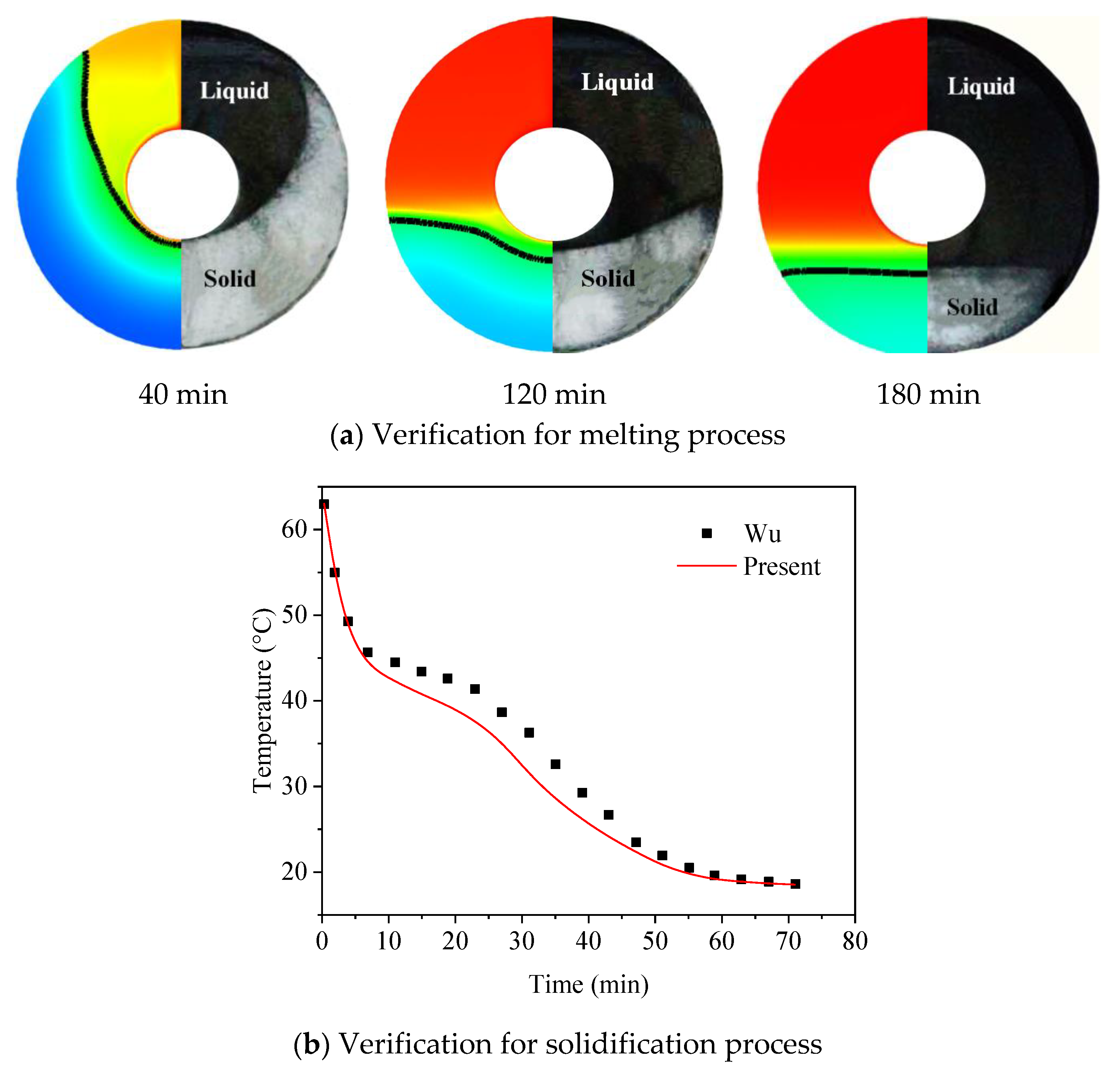
2.3. Model Verification

In this part, two test cases are performed to verify the independence of the mesh and time step, shown in Figure 2, and the liquid fraction of PCM is defined as:
F L = S T > T l S t o t a l d x d y
After the comparison, the cells of 17,539 and the time step of 0.05 s are selected in this work. To verify the accuracy in this work, two test cases are compared with existing data in the research [32,36], as shown in Figure 3. As expected, the numerical result and experiment show a good agreement, which verifies the accuracy of the present work.

3. Results and Discussion

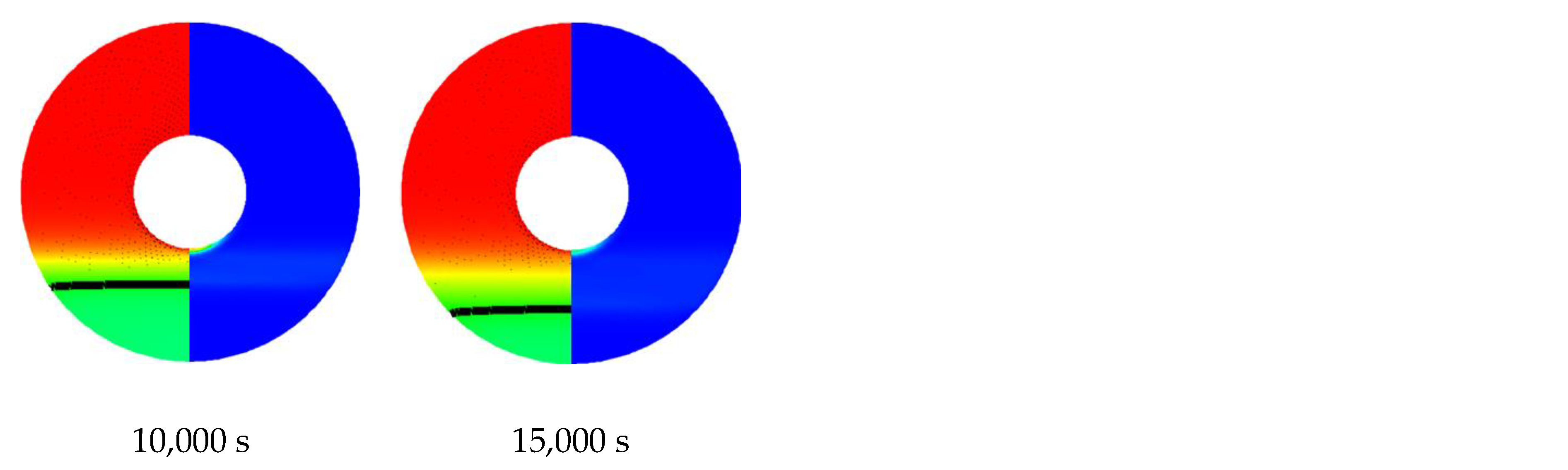
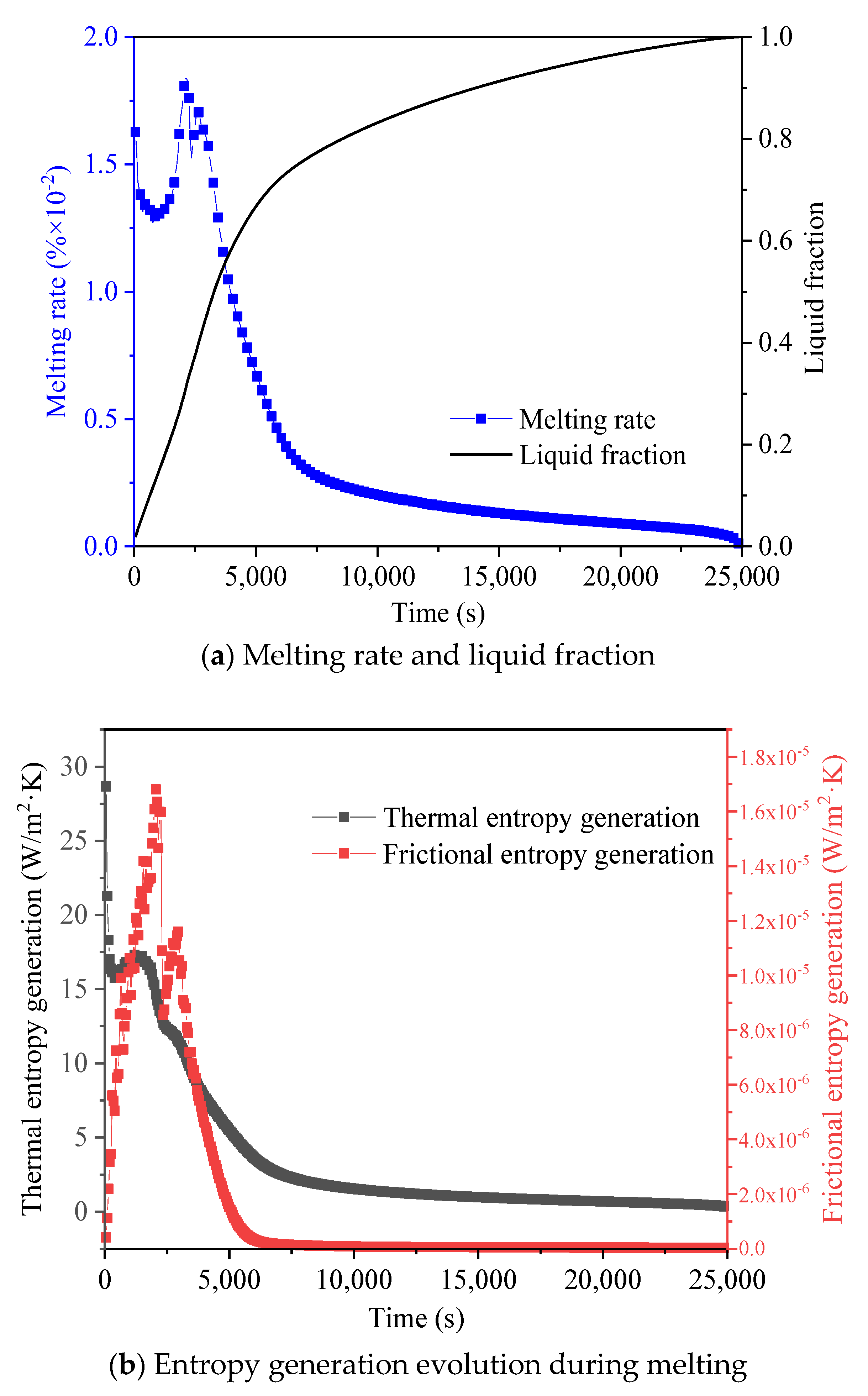
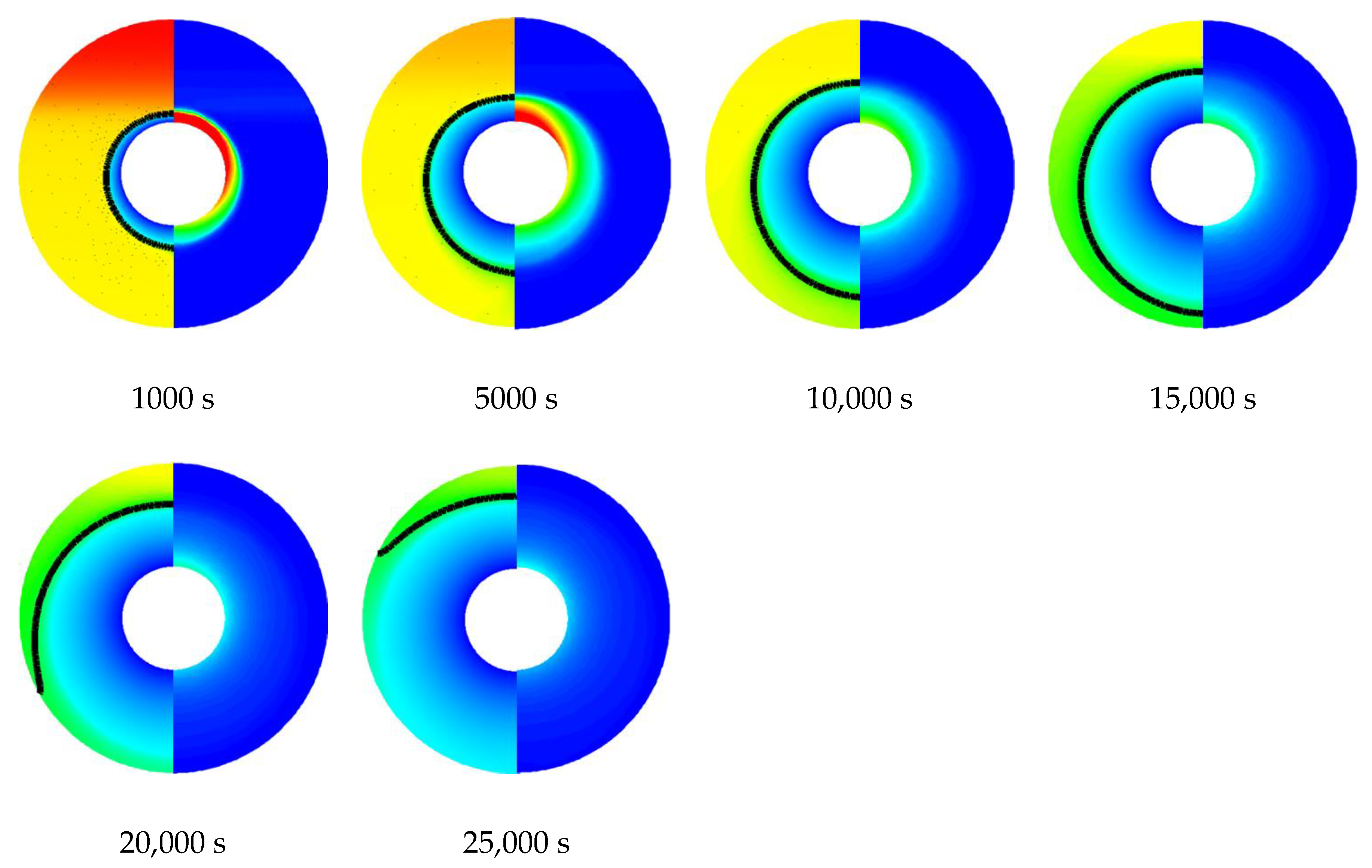
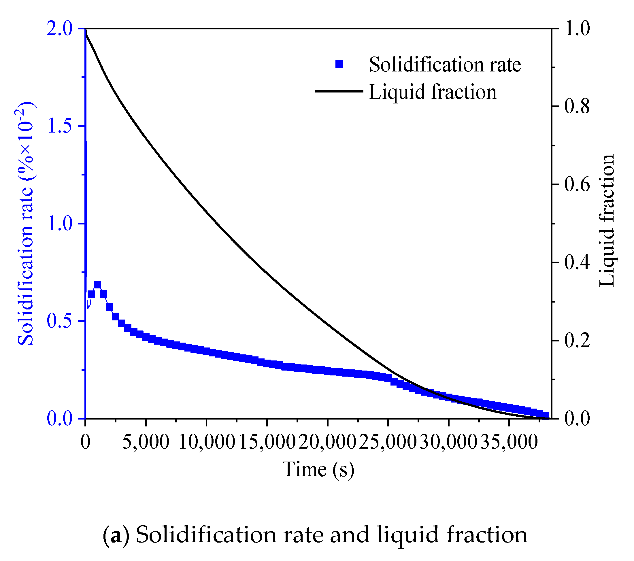
3.1. Melting and Solidification Processes for No-Fin Case

Before revealing the effects of the bifurcated fins on thermal performance and entropy generation of the LHETS unit, the case without fins is discussed and analyzed as a benchmark. The left side of Figure 4 shows the temperature distribution, liquid–solid interface and velocity vector, and the right side shows the local entropy generation distribution in the melting process. Meanwhile, Figure 5 shows the liquid fraction and entropy generation of the melting process, respectively. In the first 500 s of melting, the liquid PCM layer around the inner tube increases uniformly. At this time, there is no flow in the liquid region, and heat conduction dominates the melting. In addition, the melting rate reaches its maximum due to the huge temperature gradient between the PCM and inner tube. Correspondingly, local entropy is mainly generated in regions with large temperature gradient. It can be found from Figure 6b that the huge temperature gradient causes the heat transfer entropy to reach the maximum at the beginning of melting, and the friction entropy is zero since there is no flow in the liquid PCM. At 1000 s, natural convection occurs in the liquid region, and an obvious velocity vector appears. The liquid PCM is heated and exchange heat with the upper solid PCM, so the PCM there melts faster. As melting progressing, the thermal entropy is much bigger than the frictional entropy, which is due to the slower flow of natural convection. At 3000 s, as the liquid space further increases, natural convection begins to intensify. As a result, the melting rate increases, and the friction entropy increases. After 5000 s, the PCM in the upper part is completely melted. The smaller temperature gradient results in the suppression of natural convection, the heat transfer mechanism returns to heat conduction and melting begins to slow down. As a result, the thermal entropy and friction entropy both drop sharply and approach zero. Finally, the melting is completed in about 25,000 s.
Figure 6 shows the radial and circumferential temperature evolution for the melting process. Obviously, the temperature of Points 1–4 (see Figure 1) rises in sequence as melting progresses. It is worth noting that the temperature of PCM fluctuates before 2500 s, which is caused by the continuous mixing of high temperature and low temperature liquid PCM. In addition, there is a great lag in the radial temperature evolution and a great non-uniformity in the circumferential temperature evolution, as shown in Figure 6. Thus, the lag time, which is the time difference between various points to reach the melting point, is proposed to quantify the thermal penetration and thermal uniformity of the LHTES unit. According to the statistics, the lag times of thermal penetration and uniformity for no-fin case are 2300 s and 22,500 s, respectively. The poor thermal penetration and uniformity seriously affect the melting process.
Figure 7 shows the liquid–solid interfaces and local entropy generation during the solidification process. Additionally, Figure 8 shows the solidification rate and global entropy generation. In this work, solidification is performed after melting, so the slight overheating is considered [37]. At 1000 s, a solid PCM layer is formed around the inner tube. As the solid layer becomes thicker, the solidification rate becomes slower. It should be noted that the solid PCM layer above the inner tube is thinner than the PCM layer below the inner tube. This is because the high temperature above the LHTES unit after the melting and weak natural convection in solidification. Correspondingly, the entropy generation in the upper region is also higher than that in the lower region. Figure 8b shows the thermal entropy and friction entropy, respectively. As the temperature gradient becomes smaller, the thermal entropy sharply decreases, and the friction entropy is almost zero after 1000 s, which further proves that heat conduction is the main heat transfer mode of solidification. At about 35,000 s, the PCM completely solidified.
Figure 9 shows the lag time of no-fin case in solidification. The temperature of each point decreases as the solidification progresses, and latent heat is released when the solidification point is reached, then the temperature further decreases. Interestingly, different from melting, the radial lag time of solidification is greater than the circumferential lag time. This is because heat conduction is the main heat transfer mode of solidification, which causes solidification to be slower and more uniform than melting.

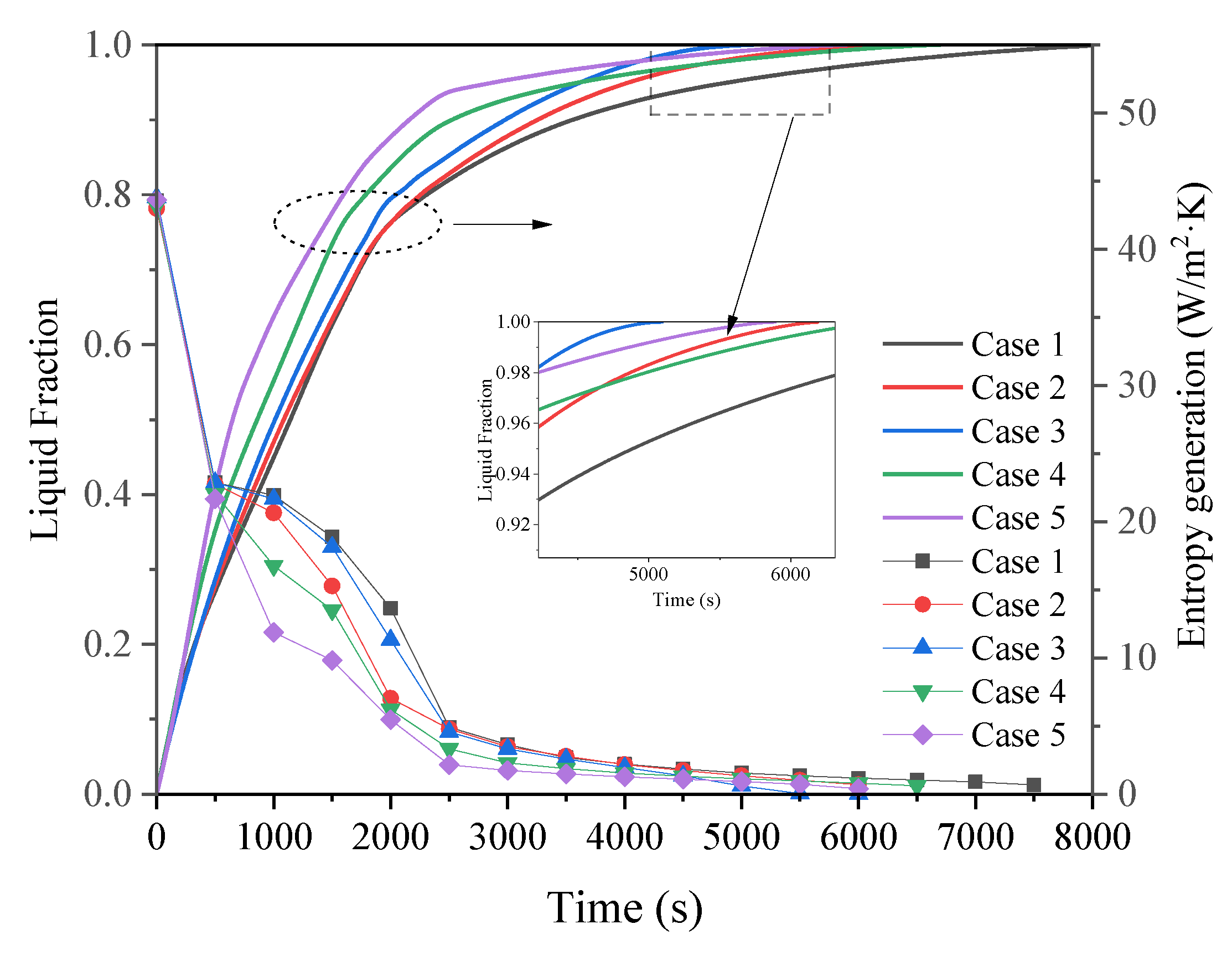
3.2. Promotion of Melting and Solidification by Bifurcated Fins

In this part, the bifurcated fins composed of straight fins are discussed firstly. According to the principle that the shortest distance between the outer edge of the fin and the shell (H1) is equal, the trunk and branch fin lengths are increased, respectively, to reveal the heat transfer enhancement mechanism of the trunk and branch fins on the phase change process, as shown in Figure 10. The fin parameters and discussed cases are shown in Table 2. Among them, Case 1 is equipped with bifurcated fins. The trunk fin lengths of Cases 2 and 3 are increased, and the H1 is shortened from 19 mm to 14 mm and 9 mm, respectively. In addition, the branch fin lengths of Cases 4 and 5 are increased on the basis of Case 1, and H1 of Cases 4 and 5 is equal to Cases 2 and 3, respectively.
Figure 11 shows the temperature distribution and entropy generation for Cases 1–5. Obviously, the heat transfer is significantly enhanced by the bifurcated fins. For Case 1, the PCM between the fins melts firstly, and natural convection is generated in the liquid PCM. Then, the liquid–solid interface further expends, and the PCM in the upper part of the LHTES unit melts faster due to the effect of natural convection. Meanwhile, the local entropy generation distribution indicates that the entropy is mainly generated in large temperature gradients region such as the inner tube and the liquid–solid interface. At 2000 s, increasing the trunk and branch fin lengths have different effects on heat transfer hysteresis zones. Increasing the trunk fin length, such as Cases 2 and 3, is beneficial to the melting of the bottom PCM, but fails to promote the heat transfer between the adjacent trunk fins. For Cases 4 and 5, the increased length of the branch fins effectively enhances the heat transfer between the adjacent trunk fins, but the PCM at the bottom of LHTES unit still has a lag in heat transfer.
Figure 12a,b shows the radial lag time and circumferential lag time of Cases 1–5 to evaluate the thermal penetration and thermal uniformity. The radial lag time is shortened from 1300 s to 700 s through increasing the branch fin lengths. However, increasing the trunk fin length does not improve the thermal penetration significantly. As for thermal uniformity, as shown in Figure 12b, increasing the trunk fin lengths (Cases 2 and 3) seems to be more effective in reducing the circumferential lag time. The extended bottom trunk fin effectively heats the PCM at the bottom of the LHTES unit.
Figure 13 shows the liquid fraction and global entropy generation for Cases 1–5. Increasing the trunk fin length is more effective in shortening melting when the H1 is certain due to better thermal uniformity. This is because at the end of melting, for the case with longer branch fins (Case 5), the heat transfer mode at Point 11 is heat conduction, and the melting is slow. For case with longer trunk fins (Case 3), natural convection still exists at points 9 and 10. Therefore, Case 3 melts faster than Case 5. Additionally, the huge temperature gradient at the beginning of melting causes the entropy generation to reach a maximum at the beginning. As melting progresses, the entropy generation gradually decreases. Obviously, the case with the longer fins generates smaller entropy. This is because the longer the fin, the stronger the heat transfer, which leads to smaller global temperature gradients and smaller entropy generation [32].
Likewise, Figure 14 shows the evolution of the temperature and entropy distribution of Cases 6–10. Among them, Cases 7 and 8 are the cases with the increase in trunk fin length, and Cases 9 and 10 are the cases with the increase in branch fin length. At the early stage of solidification, the liquid–solid interface is closely related to the geometric shape of the fins, and the solid PCM extend continuously with the shape of the fins. In addition, different from melting, the entropy during solidification seems to generate in the solid PCM region rather than the liquid–solid interface. The reason for this phenomenon is that the solidification is dominated by conduction, and the temperature gradient mainly exists in solid PCM. Interestingly, increasing the branch fin length seems to be more effective in reducing the heat transfer hysteresis region of solidification. Figure 15 further confirms this qualitative interpretation. Clearly, increasing the branch fin length has a positive effect on both heat penetration and uniformity. Furthermore, the increasing in trunk fins has no significant effect on heat transfer in solidification due to the hysteresis zone between adjacent branched fins.
Figure 16 shows the liquid fraction and global entropy generation for Cases 6–10. Compared with increasing the trunk fin length, increasing the branch fin length more effectively promotes the solidification process. On the one hand, the thermal penetration and uniformity of Cases 9 and 10 is excellent; on the other hand, the branch fins do not suppress the natural convection since the natural convection is negligible during the solidification. More importantly, increasing branch fin length more effectively reduces the global entropy generation.

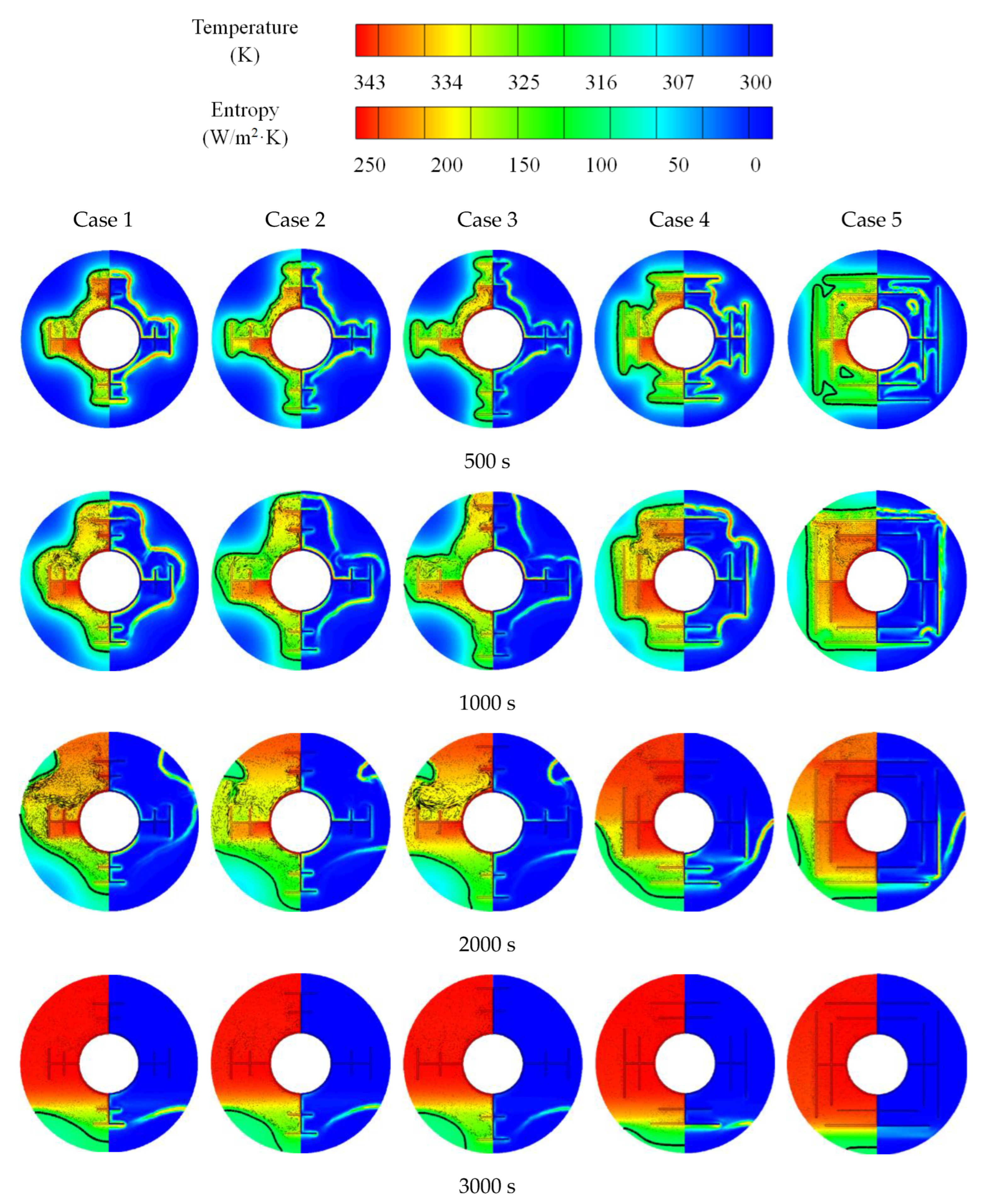
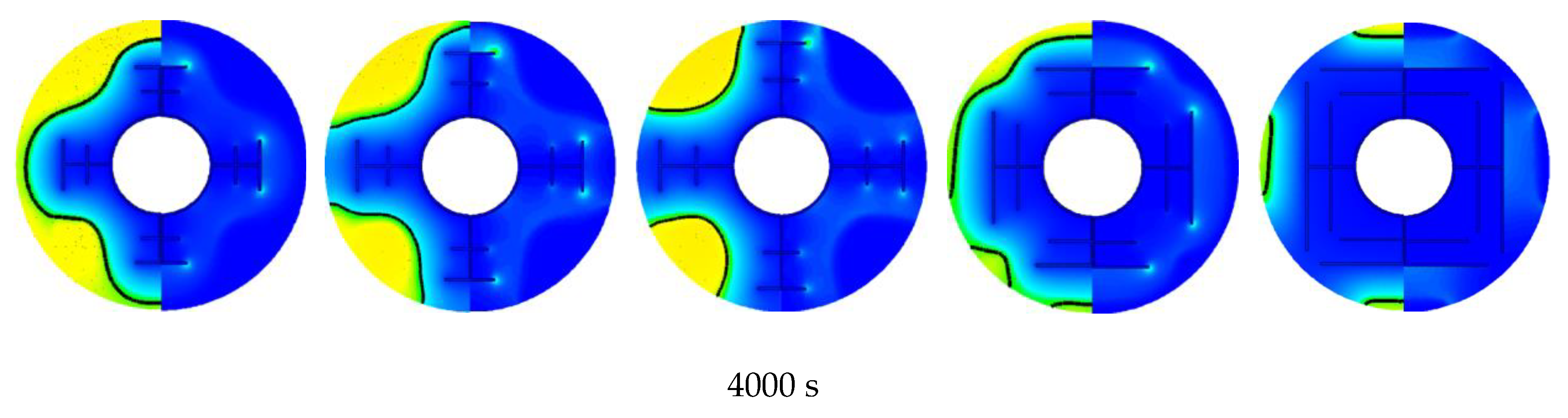
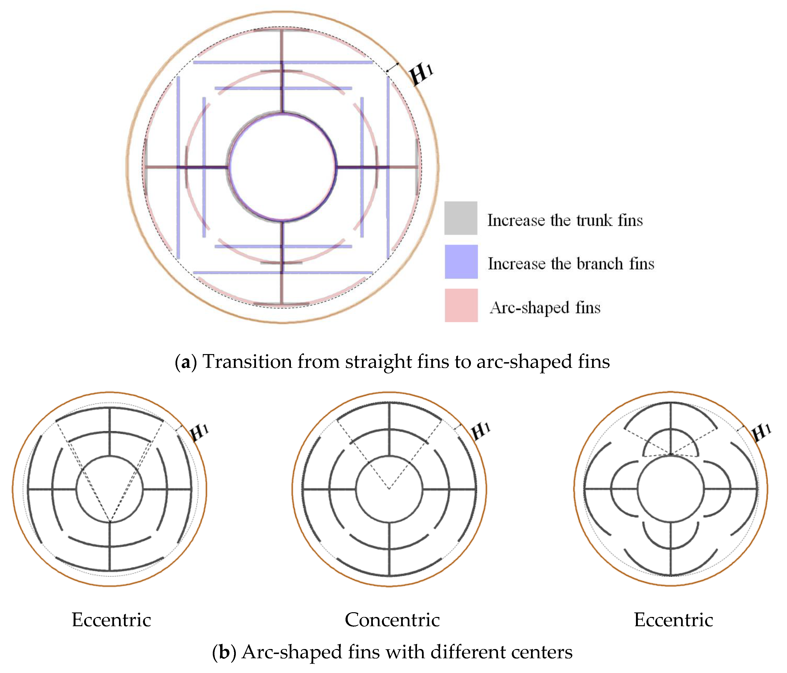
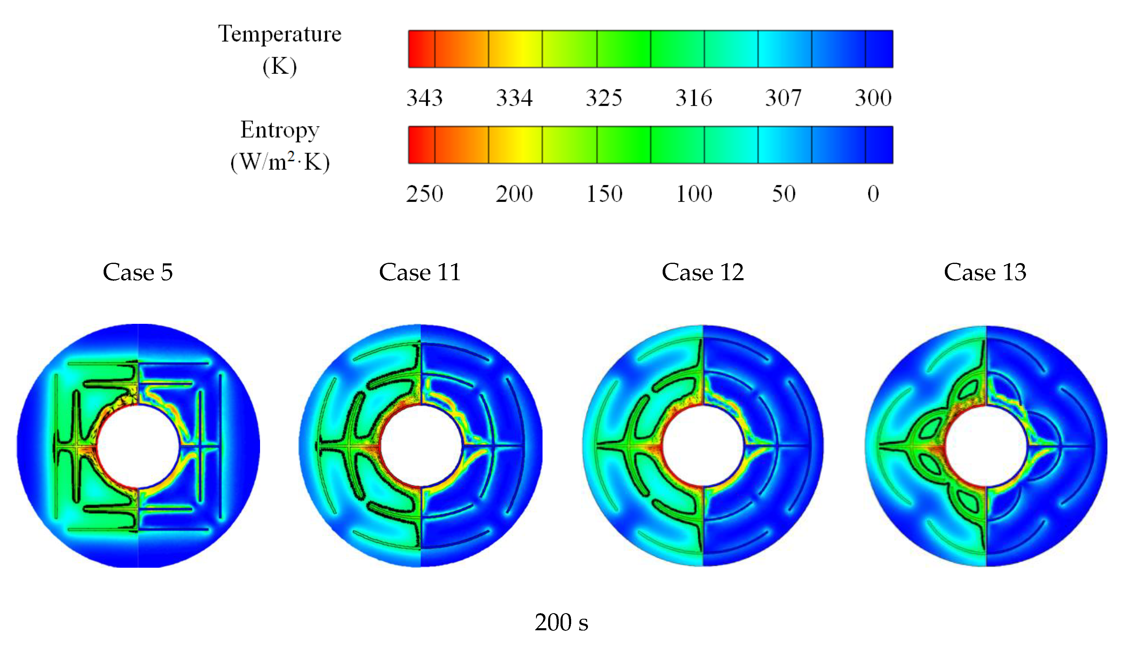
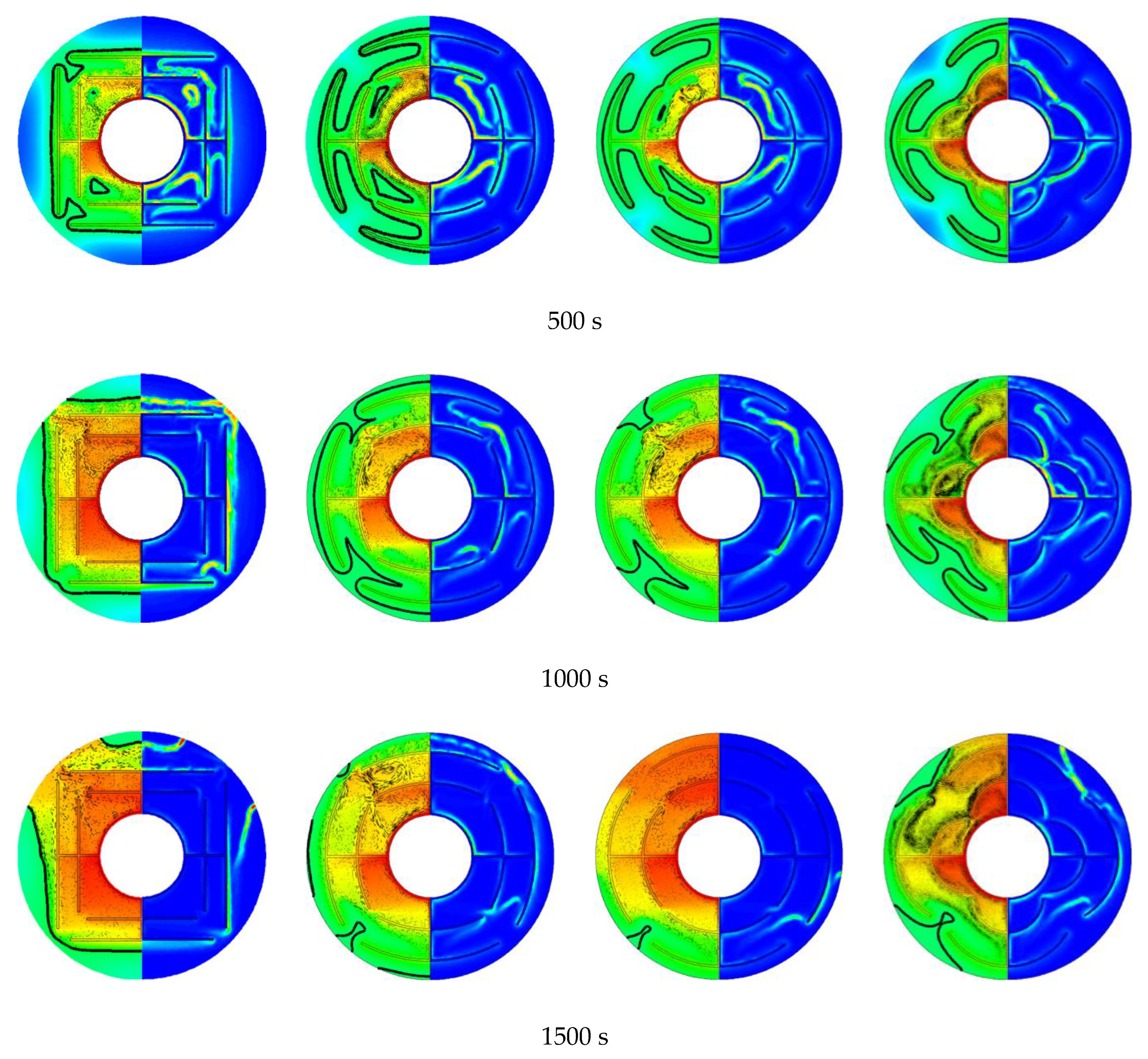
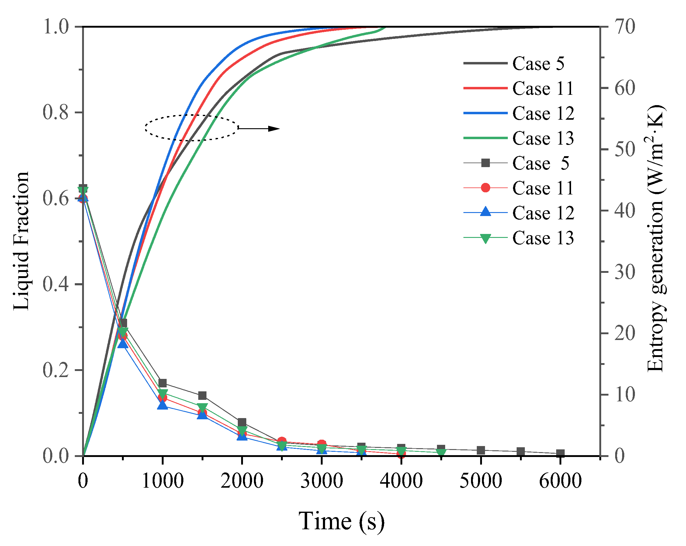
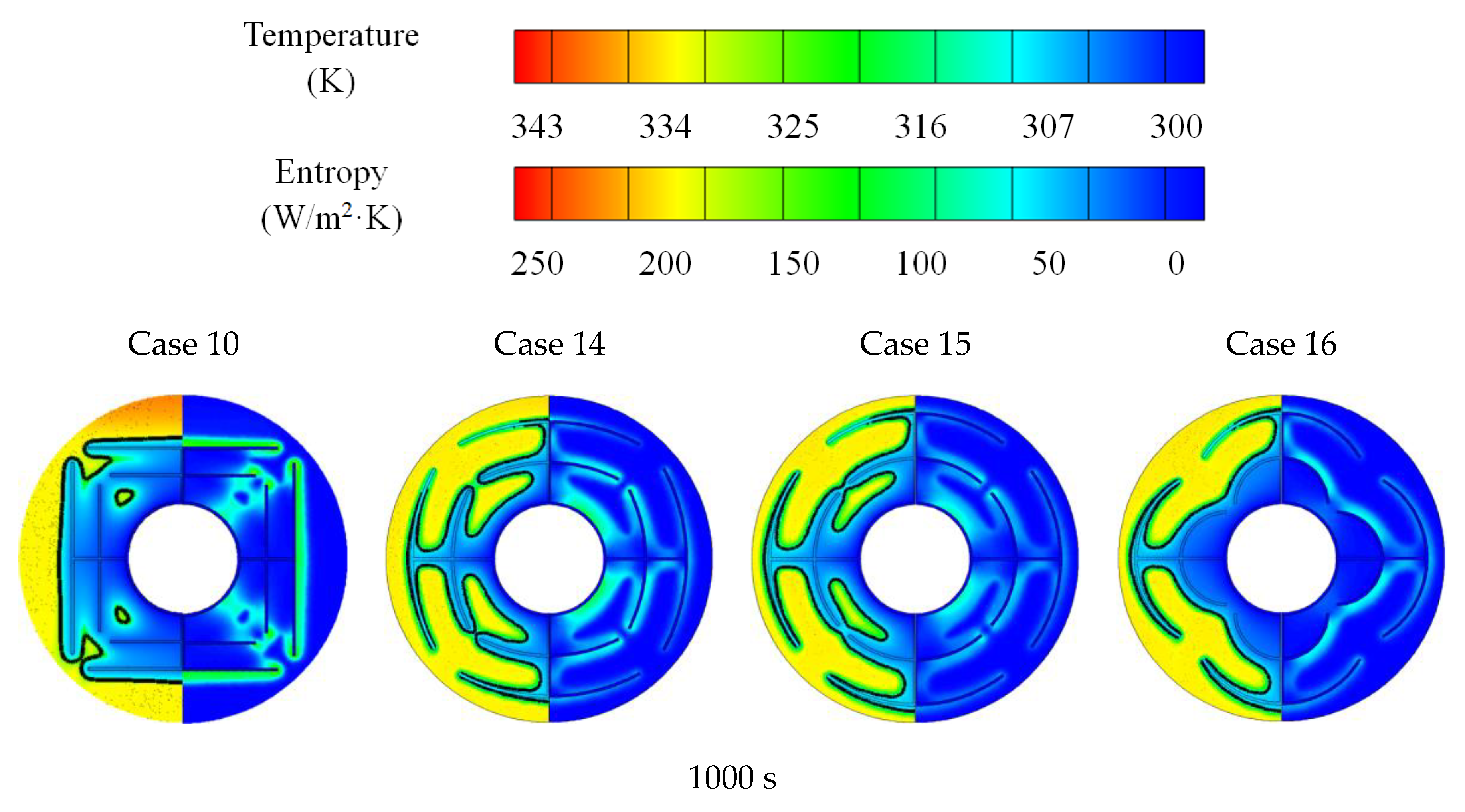
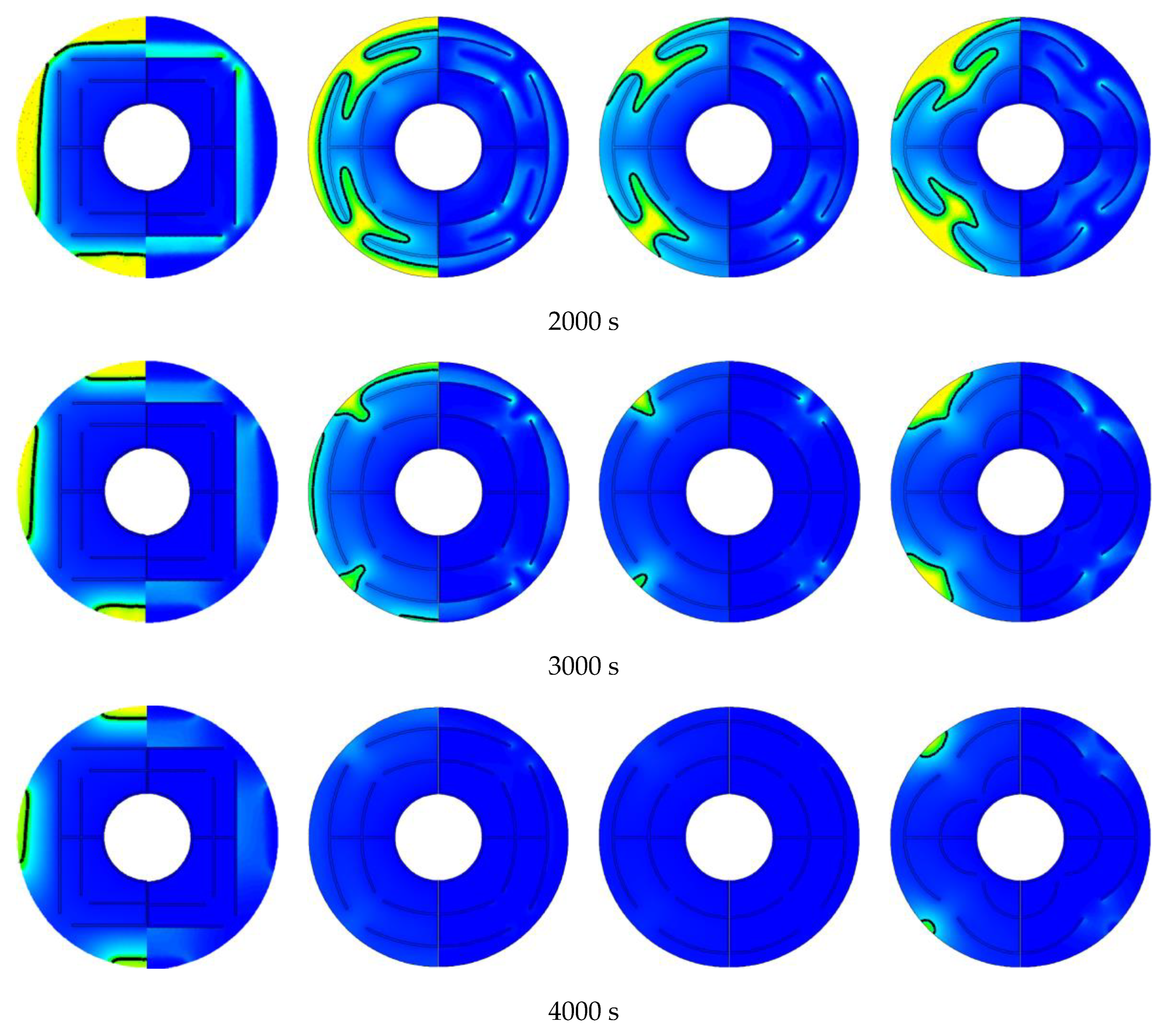
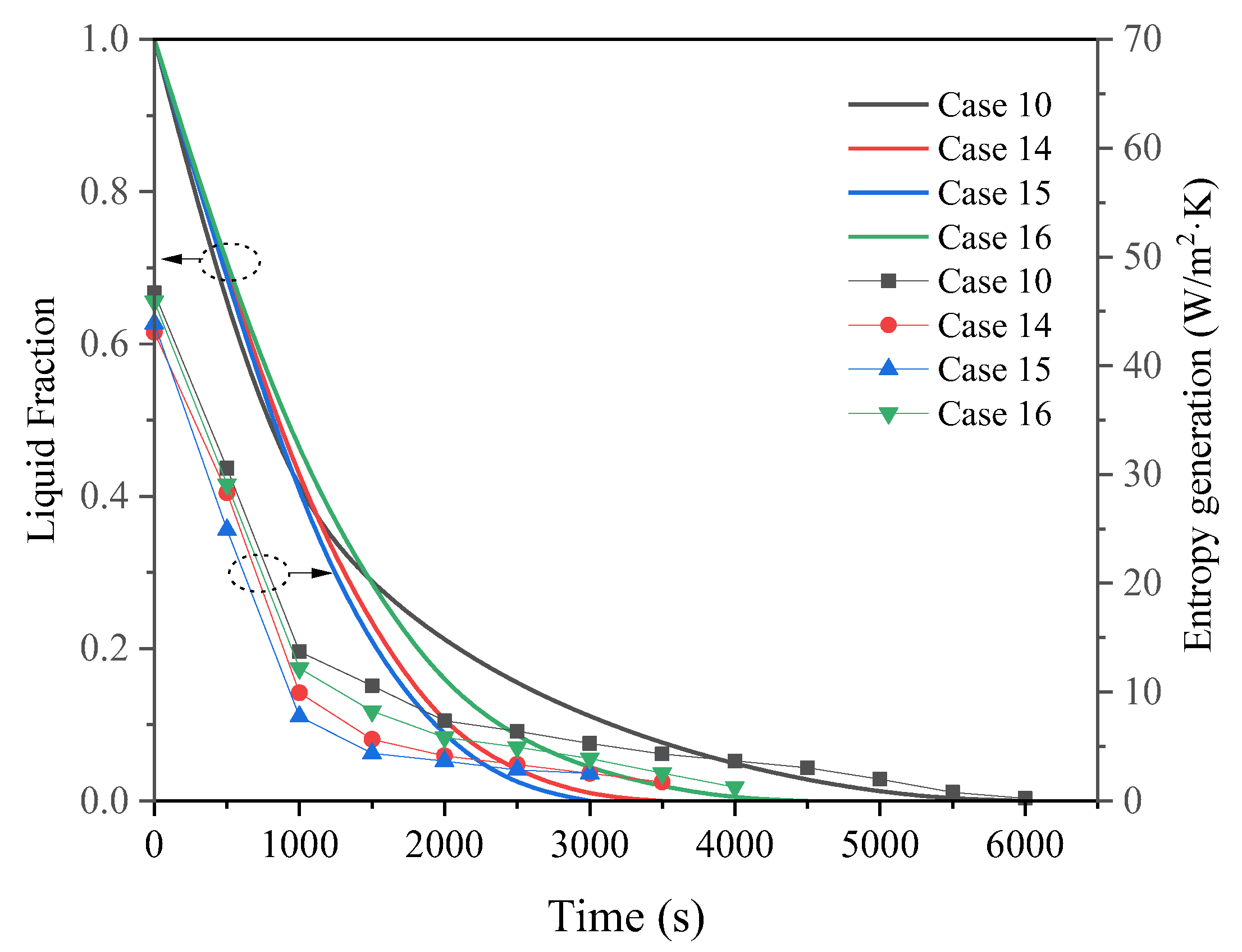
3.3. Promotion of Melting and Solidification by Arc-Shape Fins

In the previous discussion, it can be found that the trunk fins and branch fins play different roles in the thermal penetration and thermal uniformity of the PCM phase transition process. For the melting process, increasing the trunk fin length is more effective for the thermal uniformity, while for the solidification process, increasing the branch fin length seems more important. However, there is a contradiction in length increase in the trunk fins and branch fins due to the limited space. On the one hand, increasing the trunk fin length inevitably limits the increase in branch fin lengths; on the other hand, there are still hysteresis regions in the LHTES unit by increasing the trunk and branch fin lengths. Therefore, this work proposes a novel fin structure which uses arc-shaped fins instead as branches to achieve a synergistic improvement in melting and solidification in the limited space. The discussion is carried out in a later section.
Figure 17a shows the transition from straight fins to arc-shaped fins when H1 is the same (H1 = 9 mm). With the same H1, the arc-shaped fins realize the simultaneous increase in the trunk fin and the branch fin in length. In addition, the branch fins eccentric to the shell-tube LHTES unit are considered, as shown in Figure 17b, and the fin parameters and the discussed cases are shown in Table 3. Moreover, the case with straight branch fins is also compared and discussed to reveal the positive effects of the arc-shaped fins. The liquid–solid interface, temperature, velocity vector and entropy generation distribution for Cases 5 and 11–13 are shown in Figure 18. Figure 19 quantifies the thermal penetration and thermal uniformity, and Figure 20 shows the liquid fraction and global entropy generation of each case. At the beginning of melting, the liquid PCM layer is generated around the fins, and the solid PCM temperature also begins to increase significantly. After that, the temperature distribution and liquid–solid interface of cases with straight branch fins and arc-shaped fins show obvious differences. For straight branch fins, the solid PCM between the fins has almost completely melted. Correspondingly, straight branch fins improve the thermal penetration, and the liquid fraction is the highest before 1000 s. As for cases with arc-shaped fins, there is still unmelted PCM between the fins. At 1000 s, the melting of Cases 11 and 12 is significantly accelerated. For Case 13, there are heat transfer hysteresis regions between the fins and the shell due to the large curvature of the fin. The hysteresis of heat transfer is more obvious in Case 5. By quantifying the thermal uniformity, concentric are-shaped fins show the most excellent thermal uniformity and also show a shorter melting process and less global entropy generation. In the same space, the concentric arc fins shorten the melting time by 52.7% compared to straight fins.
For the solidification process, the liquid–solid interfaces, entropy distribution, thermal penetration and uniformity, liquid fraction and global entropy generation for Cases 10 and 14–16 are shown in Figure 21, Figure 22 and Figure 23, respectively. Similar to melting, the radial lag time of Case 10 is only 1000 s, and the thermal penetration of the LHTES unit is well promoted by the straight bifurcated fins. However, the circumferential lag time determines the overall solidification process. As shown in Figure 21, it can be found that there are obvious heat transfer hysteresis regions in Cases 10 and 16 after 3000 s, while Case 15 has a more uniform circumferential temperature distribution, and completely solidified within 3000 s. Therefore, compared with the thermal penetration, the thermal uniformity can more accurately reflect the phase change process of the LHTES unit. What is more, the concentric arc-shaped fins reduce the energy release time by 51.6% from the basis of straight fins by a more uniform temperature distribution.

4. Conclusions

In this work, a novel bifurcated fin configuration composed of arc-shaped fins was proposed to promote the melting and solidification process in a shell-tube latent heat thermal energy storage (LHTES) unit. Transient simulations were carried out to explore liquid–solid interfaces, temperature distribution velocity vector and entropy generation of the phase change process. Thermal penetration and thermal uniformity were quantified to evaluate the effects of fins. The major conclusions are summarized as follows:
(1)
For bifurcated fins composed of straight fins, increasing trunk fin length was more effective in the melting process in a certain space. For the solidification, however, increasing branch fin length was more effective. The straight branch fins were not compatible in shell-tube LHTES unit.
(2)
The arc-shaped fins effectively promoted thermal performance of the LHTES unit. More importantly, the arc-shaped fins concentric with the LHTES unit exhibited the best thermal uniformity the lowest global entropy generation. In the same space, the concentric arc-shaped fins shortened the energy storage time by 52.7% and the energy release time by 51.6%.
(3)
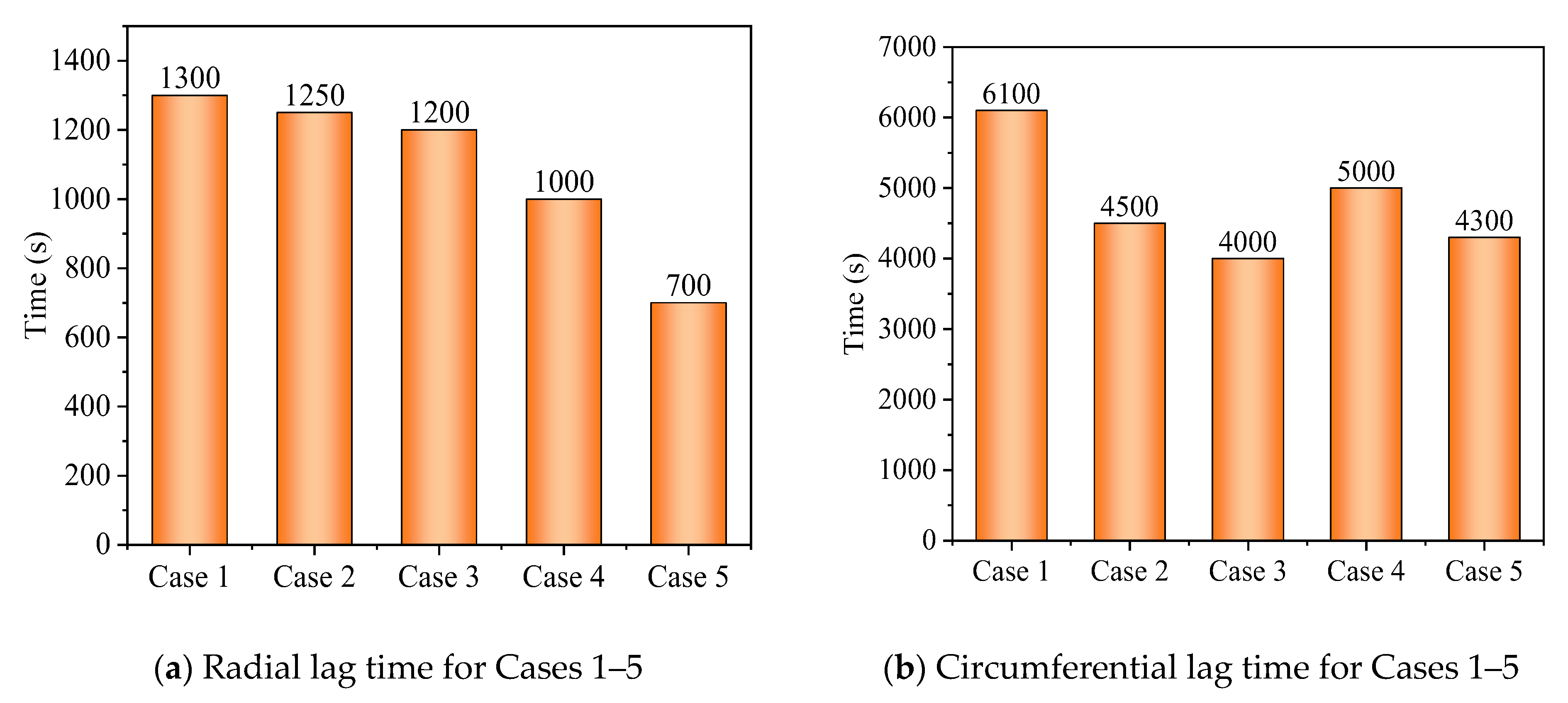
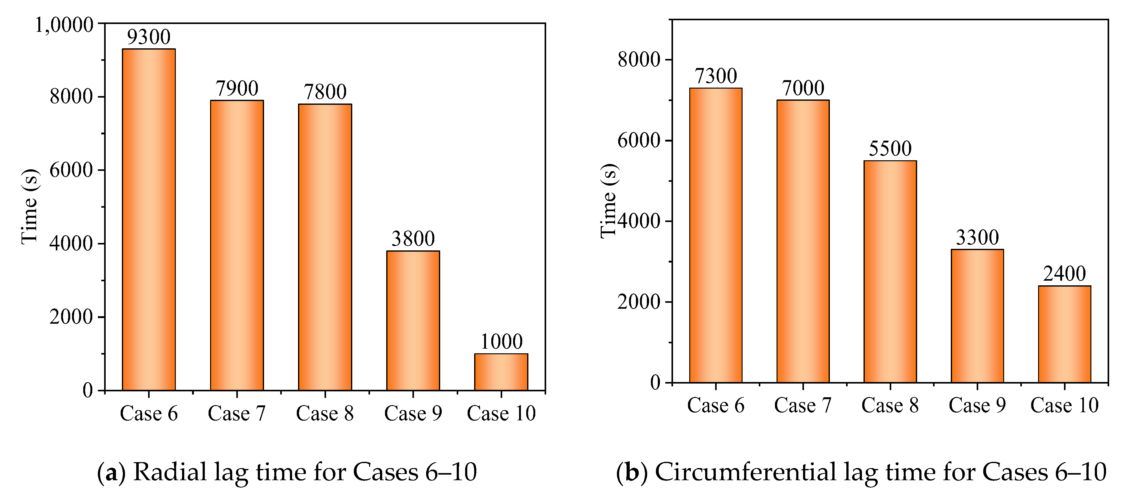
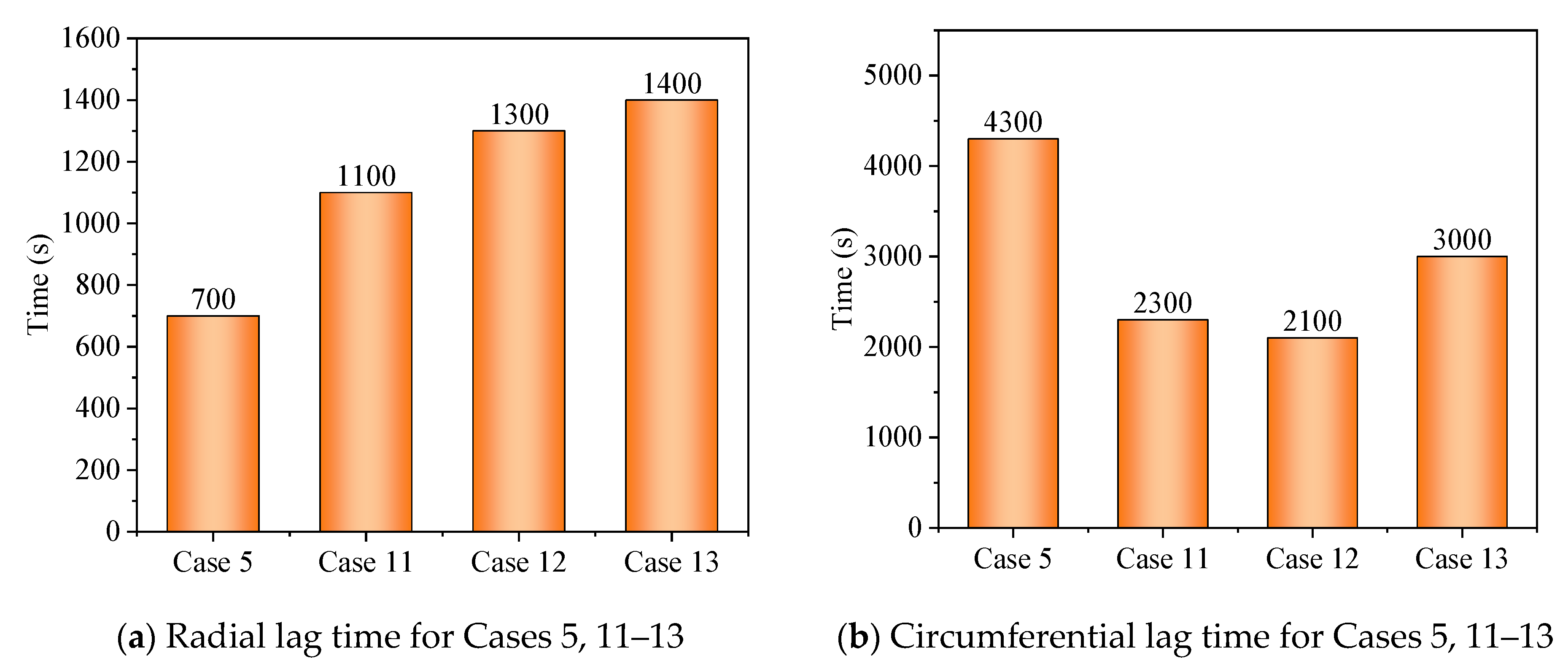
The circumferential thermal uniformity directly reflects the phase transition process. In addition, the radial thermal penetration in one direction could not comprehensively reflect the phase transition process because of the existence of the heat transfer hysteresis region. Thermal uniformity is a more important evaluation for shell-tube LHTES units.
(4)
The present conclusions are applicable to the LHTES units with single tubes. For technical LHTES units with multiple inner tubes, the applicability of arc fins still needs to be further evaluated.

Author Contributions

Q.C.: Conceptualization, Methodology, Writing—Original Draft, Supervision. J.W.: Resources, Data Curation, Writing—Original Draft, K.S.: Software, Visualization, Y.Z.: Software, Visualization. All authors have read and agreed to the published version of the manuscript.

Funding

This study was supported by National Natural Science Foundation of China (No. 52076033, 52222603).

Institutional Review Board Statement

Not applicable.

Informed Consent Statement

Not applicable.

Data Availability Statement

Not applicable.

Conflicts of Interest

The authors declare no conflict of interest.

References

  1. Kumar, A.; Saha, S.K. Performance study of a novel funnel shaped shell and tube latent heat thermal energy storage system. Renew. Energy 2021, 165, 731–747. [Google Scholar] [CrossRef]
  2. Thonon, M.; Fraisse, G.; Zalewski, L. Analytical modelling of PCM supercooling including recalescence for complete and partial heating/cooling cycles. Appl. Therm. Eng. 2021, 190, 116751. [Google Scholar] [CrossRef]
  3. Demirkran, S.G.; Cetkin, E. Emergence of rectangular shell shape in thermal energy storage applications: Fitting melted phase changing material in a fixed space. J. Energy Storage 2021, 37, 102455. [Google Scholar] [CrossRef]
  4. Mahdi, J.M.; Mohammed, H.I.; Talebizadehsardari, P. A new approach for employing multiple PCMs in the passive thermal management of photovoltaic modules. Sol. Energy 2021, 222, 160–174. [Google Scholar] [CrossRef]
  5. Li, X.; Duan, J.; Simon, T. Nonuniform metal foam design and pore-scale analysis of a tilted composite phase change material system for photovoltaics thermal management. Appl. Energy 2021, 298, 117203. [Google Scholar] [CrossRef]
  6. Wang, J.; Yu, K.; Duan, R. Enhanced Thermal Management by Introducing Nanoparticle Composite Phase Change Materials for Cooling Multiple Heat Sources Systems. Energy 2021, 227, 120495. [Google Scholar] [CrossRef]
  7. Rathore, P.; Shukla, S.K. An experimental evaluation of thermal behavior of the building envelope using macroencapsulated PCM for energy savings. Renew. Energy 2020, 149, 1300–1313. [Google Scholar] [CrossRef]
  8. Wen, R.; Liu, Y.; Yang, C. Enhanced thermal properties of stearic acid/carbonized maize straw composite phase change material for thermal energy storage in buildings. J. Energy Storage 2021, 36, 102420. [Google Scholar] [CrossRef]
  9. Peng, W.; Sadaghiani, O.K. Thermal function improvement of phase-change material (PCM) using alumina nanoparticles in a circular-rectangular cavity using Lattice Boltzmann method. J. Energy Storage 2021, 37, 102493. [Google Scholar] [CrossRef]
  10. Hosseinzadeh, K.; Montazer, E.; Shafii, M.B. Solidification enhancement in triplex thermal energy storage system via triplets fins configuration and hybrid nanoparticles. J. Energy Storage 2021, 34, 102177. [Google Scholar] [CrossRef]
  11. Li, W.Q.; Guo, S.J.; Tan, L. Heat transfer enhancement of nano-encapsulated phase change material (NEPCM) using metal foam for thermal energy storage. Int. J. Heat Mass Tran. 2021, 166, 120737. [Google Scholar] [CrossRef]
  12. Dinesh, B.; Bhattacharya, A. Comparison of energy absorption characteristics of PCM-metal foam systems with different pore size distributions. J. Energy Storage 2020, 28, 101190. [Google Scholar] [CrossRef]
  13. Zhao, C.; Opolot, M.; Liu, M. Numerical study of melting performance enhancement for PCM in an annular enclosure with internal-external fins and metal foams. Int. J. Heat Mass Tran. 2020, 150, 119348. [Google Scholar] [CrossRef]
  14. Qu, Y.; Wang, S.; Zhou, D. Experimental study on thermal conductivity of paraffin-based shape-stabilized phase change material with hybrid carbon nano-additives. Renew. Energy 2020, 146, 2637–2645. [Google Scholar] [CrossRef]
  15. Kuziel, A.W.; Dzido, G.; Turczyn, R. Ultra-long carbon nanotube-paraffin composites of record thermal conductivity and high phase change enthalpy among paraffin-based heat storage materials. J. Energy Storage 2021, 6, 102396. [Google Scholar] [CrossRef]
  16. Sodhi, G.S.; Muthukumar, P. Compound charging and discharging enhancement in multi-PCM system using non-uniform fin distribution. Renew. Energy 2021, 171, 299–314. [Google Scholar] [CrossRef]
  17. Mao, Q.; Li, Y. Experimental and numerical investigation on enhancing heat transfer performance of a phase change thermal storage tank. J. Energy Storage 2020, 31, 101725. [Google Scholar] [CrossRef]
  18. Raul, A.; Saha, S.K.; Jain, M. Transient performance analysis of concentrating solar thermal power plant with finned latent heat thermal energy storage. Renew. Energy 2020, 145, 1957–1971. [Google Scholar] [CrossRef]
  19. Jia, X.; Zhai, X.; Cheng, X. Thermal performance analysis and optimization of a spherical PCM capsule with pin-fins for cold storage. Appl. Therm. Eng. 2018, 148, 929–938. [Google Scholar] [CrossRef]
  20. Paria, S.; Baradaran, S.; Amiri, A. Performance evaluation of latent heat energy storage in horizontal shell-and-finned tube for solar application. J. Therm. Anal. Calorim. 2016, 123, 1371–1381. [Google Scholar] [CrossRef]
  21. Deng, S.; Nie, C.; Wei, G. Improving the melting performance of a horizontal shell-tube latent-heat thermal energy storage unit using local enhanced finned tube. Energy Build. 2019, 183, 161–173. [Google Scholar] [CrossRef]
  22. Al-Abidi, A.; Mat, S.; Sopian, K. Experimental study of melting and solidification of PCM in a triplex tube heat exchanger with fins. Energy Build. 2014, 68, 33–41. [Google Scholar] [CrossRef]
  23. Zarei, M.J.; Bazai, H.; Sharifpur, M. The Effects of Fin Parameters on the Solidification of PCMs in a Fin-Enhanced Thermal Energy Storage System. Energies 2020, 13, 198. [Google Scholar] [CrossRef] [Green Version]
  24. Kunal, B.; Mohit, P.; Saha, S.K. Estimation of thermal performance and design optimization of finned multitube latent heat thermal energy storage. J. Energy Storage 2018, 19, 135–144. [Google Scholar]
  25. Al-Abidi, A.A.; Mat, S.; Sopian, K. Numerical study of PCM solidification in a triplex tube heat exchanger with internal and external fins. Int. J. Heat Mass Tran. 2013, 61, 684–695. [Google Scholar] [CrossRef]
  26. Yldz, A.; Arc, M.; Nieti, S. Numerical investigation of natural convection behavior of molten PCM in an enclosure having rectangular and tree-like branching fins. Energy 2020, 207, 118223. [Google Scholar] [CrossRef]
  27. Alizadeh, M.; Khosseinzadeh, H. Solidification acceleration in a triplex-tube latent heat thermal energy storage system using V-shaped fin and nano-enhanced phase change material. Appl. Therm. Eng. 2019, 163, 114436. [Google Scholar] [CrossRef]
  28. Al-Mudhafar, A.; Nowakowski, A.F.; Nicolleau, F.G. Enhancing the thermal performance of PCM in a shell and tube latent heat energy storage system by utilizing innovative fins. Energy Rep. 2021, 7, 120–126. [Google Scholar] [CrossRef]
  29. Sciacovelli, A.; Gagliardi, F.; Verda, V. Maximization of performance of a PCM latent heat storage system with innovative fins. Appl. Energy 2015, 137, 707–715. [Google Scholar] [CrossRef]
  30. Hosseinzadeh, K.H.; Alizadeh, M.; Ganji, D.D. Solidification process of hybrid nano-enhanced phase change material in a LHTESS with tree-like branching fin in the presence of thermal radiation. J. Mol. Liq. 2018, 275, 909–925. [Google Scholar] [CrossRef]
  31. Zhang, C.; Li, J.; Chen, Y. Improving the energy discharging performance of a latent heat storage (LHS) unit using fractal-tree-shaped fins. Appl. Energy 2020, 259, 114102. [Google Scholar] [CrossRef]
  32. Cao, X.; Yuan, Y.; Xiang, B. Effect of natural convection on melting performance of eccentric horizontal shell and tube latent heat storage unit. Sustain. Cities. Soc. 2018, 38, 571–581. [Google Scholar] [CrossRef]
  33. Mallya, N.; Haussener, S. Buoyancy-driven melting and solidification heat transfer analysis in encapsulated phase change materials. Int. J. Heat Mass Tran. 2021, 164, 120525. [Google Scholar] [CrossRef]
  34. Nie, C.; Liu, J.; Deng, S. Effect of geometry modification on the thermal response of composite metal foam/phase change material for thermal energy storage. Int. J. Heat Mass Tran. 2021, 165, 120652. [Google Scholar] [CrossRef]
  35. Guelpa, E.; Sciacovelli, A.; Verda, V. Entropy generation analysis for the design improvement of a latent heat storage system. Energy 2013, 53, 128–138. [Google Scholar] [CrossRef] [Green Version]
  36. Wu, S.; Huang, Y.; Zhang, C. Role of tree-shaped fins in charging performance of a latent heat storage unit. Int. J. Energy Res. 2020, 44, 4800–4811. [Google Scholar] [CrossRef]
  37. Chen, S.B.; Saleem, S.; Alghamdi, M.N. Combined effect of using porous media and nano-particle on melting performance of PCM filled enclosure with triangular double fins. Case Stud. Therm. Eng. 2021, 25, 100939. [Google Scholar] [CrossRef]
Figure 1. Model of LHTES unit with bifurcated fins.
Energies 15 07799 g001
Figure 2. Time-step and mesh-size tests. (a) Time step and (b) mesh size.
Energies 15 07799 g002
Figure 3. Verification of numerical model.
Energies 15 07799 g003
Figure 4. Temperature distribution, liquid–solid interface (left side) and local entropy generation (right side) for no-fin case in melting.
Energies 15 07799 g004aEnergies 15 07799 g004b
Figure 5. Liquid fraction and entropy generation for melting process.
Energies 15 07799 g005
Figure 6. Evaluation of thermal penetration and thermal uniformity for melting.
Energies 15 07799 g006
Figure 7. Temperature distribution, liquid–solid interface (left side) and local entropy generation (right side) for no-fin case in solidification.
Energies 15 07799 g007aEnergies 15 07799 g007b
Figure 8. Liquid fraction and entropy generation for solidification process.
Energies 15 07799 g008aEnergies 15 07799 g008b
Figure 9. Evaluation of thermal penetration and thermal uniformity for solidification.
Energies 15 07799 g009
Figure 10. Two modes to increase the fin length.
Energies 15 07799 g010
Figure 11. Melting process for Cases 1–5.
Energies 15 07799 g011
Figure 12. Thermal penetration and thermal uniformity for Cases 1–5.
Energies 15 07799 g012
Figure 13. Liquid fraction and global entropy generation.
Energies 15 07799 g013
Figure 14. Solidification process for Cases 6–10.
Energies 15 07799 g014aEnergies 15 07799 g014b
Figure 15. Thermal penetration and thermal uniformity for Cases 6–10.
Energies 15 07799 g015
Figure 16. Liquid fractions and global entropy generation for Cases 6–10.
Energies 15 07799 g016
Figure 17. Schematic of arc-shaped fins.
Energies 15 07799 g017
Figure 18. Melting process for Cases 5, 11–13.
Energies 15 07799 g018aEnergies 15 07799 g018b
Figure 19. Thermal penetration and thermal uniformity for Cases 5, 11–13.
Energies 15 07799 g019
Figure 20. Liquid fractions and entropy generation for Cases 5, 11–13.
Energies 15 07799 g020
Figure 21. Solidification process for Cases 10, 14–16.
Energies 15 07799 g021aEnergies 15 07799 g021b
Figure 22. Thermal penetration and thermal uniformity for Cases 10, 14–16.
Energies 15 07799 g022
Figure 23. Liquid fractions and entropy generation for Cases 10, 14–16.
Energies 15 07799 g023
Table 1. Thermal parameters of paraffin and aluminum.
ParameterUnitParaffin (RT50)Aluminum
Specific heat capacity(kJ/kg·K)2.0947
Melting temperature(°C)51-
Solidification temperature(°C)45
Latent heat(kJ/kg)168-
Thermal conductivity(W/m·K)0.2237
Density(kg/m3)8002.7 × 103
Thermal expansion coefficientK−10.0006-
Dynamic viscosity(Pa·s)0.004
Table 2. Bifurcated fin parameters and discussed cases.
Case No.H1 (mm)L1 (mm)L2 (mm)P1 + P2 (mm)State
Case 1197.910.520Melting
Case 2147.910.525Melting
Case 397.910.530Melting
Case 41417.623.120Melting
Case 5926.534.620Melting
Case 6197.910.520Solidification
Case 7147.910.525Solidification
Case 897.910.530Solidification
Case 91417.623.120Solidification
Case 10926.534.620Solidification
Table 3. Arc-shaped fin parameters and discussed cases.
Case No.L1 (mm)L2 (mm)P1 + P2 (mm)Center of the Upper arc Fin (mm)State
Case 1126.534.630(0, −40)Melting
Case 1226.534.633(0, 0)Melting
Case 1326.534.633(0, 40)Melting
Case 1426.534.630(0, −40)Solidification
Case 1526.534.633(0, 0)Solidification
Case 1626.534.633(0, 40)Solidification
Publisher’s Note: MDPI stays neutral with regard to jurisdictional claims in published maps and institutional affiliations.

