Article

Modeling and Experimental Verification of the Required Power for Electrically Heated Clothing

1
Department of Microelectronics and Computer Science, Lodz University of Technology, 93-005 Lodz, Poland
2
Department of Personal Protective Equipment, Central Institute for Labour Protection—National Research Institute Lodz, 90-133 Lodz, Poland
3
Department of Ergonomics, Central Institute for Labour Protection—National Research Institute Warsaw, 00-701 Warsaw, Poland
*
Author to whom correspondence should be addressed.
Energies 2022, 15(20), 7713; https://doi.org/10.3390/en15207713
Submission received: 17 September 2022 / Revised: 11 October 2022 / Accepted: 13 October 2022 / Published: 19 October 2022

Abstract

:
The article presents simple modeling and experimental verification of the power required for thermal comfort in electrically heated clothing. The clothing consists of a jumpsuit with embedded heating insets, controlled by a dedicated microprocessor system. The user is able to set heating power using a smartphone app. The experiments, conducted in a mobile freezing chamber, aimed at verification of the model of theoretical power (according to ISO 11079) required to maintain thermal comfort in ambient temperatures below 0 °C. Three participants were asked to adjust heating power to reach thermal comfort. The experiment revealed the required power to be only 40–60% of the theoretical one, meaning that the design of the electrically heating clothing relying solely on the theoretical models and standards would lead to oversizing of the heating system power. Further study indicated that the mean skin temperature by itself is not sufficient as an input to the algorithm for automatic maintaining of thermal comfort, even in stationary conditions.

1. Introduction

Electrically heated clothing is an attractive solution of the problem of thermal insulation vs. convenience of use. In traditional clothing obtaining high thermal resistivity requires, even with modern insulation materials, substantial bulk. This means weight and movements restrictions. Moreover, passive clothing cannot adapt to the changing external or internal environment conditions. This is particularly troublesome when the user substantially alters the performed activity during exposure, for example switches between standing still and going fast uphill. In such a situation the same set of passive clothing may be at the same time too cold (when standing still) and too warm (when going uphill).
When designing electrically heated clothing it is crucial to match the heating power with the passive insulation value of clothing (often expressed in clo unit, equal to 0.155 W/m2K) and the desired range of external temperatures. ISO 11079 [1] presents one of the possible approaches towards this goal. However, it does not take into account many possible factors. For this reason, experimental verification in a controlled environment is important. This article reports results of such verification.
The main goal of the research was to check whether the power values calculated on the basis of the available standards (ISO 11079) are appropriate and suitable for design of protective clothing for mountain rescuers working in real-life scenarios. The article is a revised and expanded version of a paper presented at the 29th International Conference Mixed Design of Integrated Circuits and Systems, held in Wrocław, Poland on 23–25 June 2022 [2].

2. State-of-Art

Electrically heated clothing of many different kinds is currently available commercially. However, many (if not most) of them are in fact novelty items, serving little practical purpose, due to poor heating power, small capacity of the battery or small area of the heating insets [3,4,5,6]. The design of garments useful in professional application is still in its infancy.
The initial stage for electrically heated clothing design is the thermal analysis. In many cases the focus is placed on the fabric itself instead of heat production. However, one of the important questions is of the required heating power. This power can be calculated using various models of different level of complication [7,8,9,10,11]. Some of these models have now the range of standards. The important drawback of the model-based computations is the fact that even the more sophisticated models often exhibit poor accuracy, or are limited to a narrow range of environmental conditions (usually the external air temperature is the limiting factor) [12]. In particular, performance of the models in cold environment is usually poor [13]. Moreover, the elaborate models often require a lot of data and measurements as their inputs, which may be difficult to obtain, leading to far-reaching simplifications [14]. Finally, the theoretical models do not allow for the variability of user preferences—thermal comfort is largely a subjective phenomenon.
Another possible approach is the use of a thermal manikin (see Section 3.2 for a description of an example device). Manikins are used to experimentally determine thermal insulation of clothing: the heating power of the manikin is adjusted so that its surface temperature remains constant. As the heating power is equal to the heat being lost (through the clothing), and both the manikin and ambient temperatures are known, it is easy to compute thermal insulation. The same approach can be used for electrically heated clothing—additional heat generated by the clothing will reduce the power requirements of the manikin itself, resulting in observed higher thermal insulation of the clothing. Although this approach has been discussed in the literature [15], it is not commonly employed. One possible reason is the fact that in the electrically heated clothing the power is administered in a very nonuniform manner, possibly preventing correct temperature readout by the limited number of the manikin’s sensors, thus undermining the whole computations.
Evaluation of heating performance using other methods has also been reported in the literature, albeit the approaches rarely addressed the question of thermal comfort in real-life scenarios. For example, in [16] the authors evaluated effectiveness of warmers for gloves by recording temperature changes inside gloves placed in a climatic chamber; no subjective human factor was introduced in the experiment.
Some effort has also been put into determination of the most suitable placement of heating insets. Although this does not directly address the problem of the required power, it may lead to reduction of the required power due to better management of thermal losses and selection of areas responsible for thermal comfort sensation. This kind of study was reported in [17], its results for cold environment were similar to the placement selected by the authors of this article.
Yet another approach towards optimization of heating power was presented in [18], where the authors attempted to numerically model and analyse the heating product, with the aim to minimise heat losses and improve temperature distribution. Their study, however, was targeted at heating blanket, rather than wearable clothes. Application of a model to a piece of clothing was presented in [19]: the authors developed a numerical model of heat transfer mechanism and used this model to control heating levels of an electrically heated jacket. Although their approach resulted in thermal comfort of the subject, the proposed method required three separate temperature sensors for each heating pad.

3. Materials and Methods

3.1. ISO 11079 Standard

This standard is applicable for cold environments. It enables calculation of the clothing insulation required for thermal balance, IREQmin, and the clothing insulation required for thermal comfort, IREQneutral. According to the ISO 11079 standard, the first value “defines a minimal thermal insulation required to maintain body thermal equilibrium at a subnormal level of mean body temperature”, while the second “is defined as the thermal insulation required to provide conditions of thermal neutrality, i.e., thermal equilibrium maintained at a normal level of mean body temperature”. In this research IREQneutral is of interest, as the aim is to provide thermal comfort. Besides, the users can easily report when they are in comfort, while subjectively determining the state of border thermal equilibrium is not possible.
The computations in the standard are based on Equation (1) (see also [20])
MW = Eres + Cres + E + K + R + C + S,
where the variables are defined as follows: M—metabolic rate, W—effective mechanical power, Cres—respiratory heat exchange through convection, Eres—respiratory heat exchange through evaporation, E—evaporative heat exchange, K—conductive heat exchange, R—radiative heat exchange, C—convective heat exchange, S—body heat storage rate. Do note that the standard expresses all these values in W/m2, that is power per body surface area (as heat loss flux).
After expressing some of these variables in term of the others, readily measurable, and thanks to some simplifications it is possible to relate the following variables using an iterative formula:
  • Air temperature;
  • Mean radiant temperature;
  • Air velocity;
  • Metabolic rate;
  • Thermal insulation of clothing.
A Java applet is available that simplifies the calculations [21].

3.2. Newton-Type Thermal Manikin

Thermal manikin is a basic apparatus used to evaluate thermal insulation of clothing. In the research, Newton-type thermal manikin (Measurement Technology Northwest, Seattle, WA, USA) was used. It is made of a thermally conductive carbon–epoxy composite shell with integrated heating elements and sensors. This is a full-size male thermal manikin that has movable hip, knee, shoulder, elbow and ankle joints. The manikin can operate in the temperature range −20…50 °C and in relative humidity in the range 0…100%. It consists of 34 independently controlled segments and allows for evaluation of both clothing thermal insulation (i.e., dry heat exchange) and evaporative resistance (i.e., wet heat exchange). Laboratory tests of clothing thermal insulation are based on the assumptions from the following standards: EN ISO 15831 [22] and EN 342 [23]. The test principle is based on evaluation of the power needed to be delivered to the thermal manikin in order to keep it at constant surface temperature of 34 °C, in given conditions. On this basis, clothing thermal insulation is calculated and expressed in m2K/W or clo [24].

3.3. Mobile Freezing Chamber

The experiment was conducted in a chamber in which air temperature could be controlled at temperatures below 0 °C. Its floor plan dimensions were 4.20 m by 2.15 m, with height of 2.10 m. There was no forced air movement in the chamber (apart from the movement caused by the fans of the evaporator unit, which was negligible).

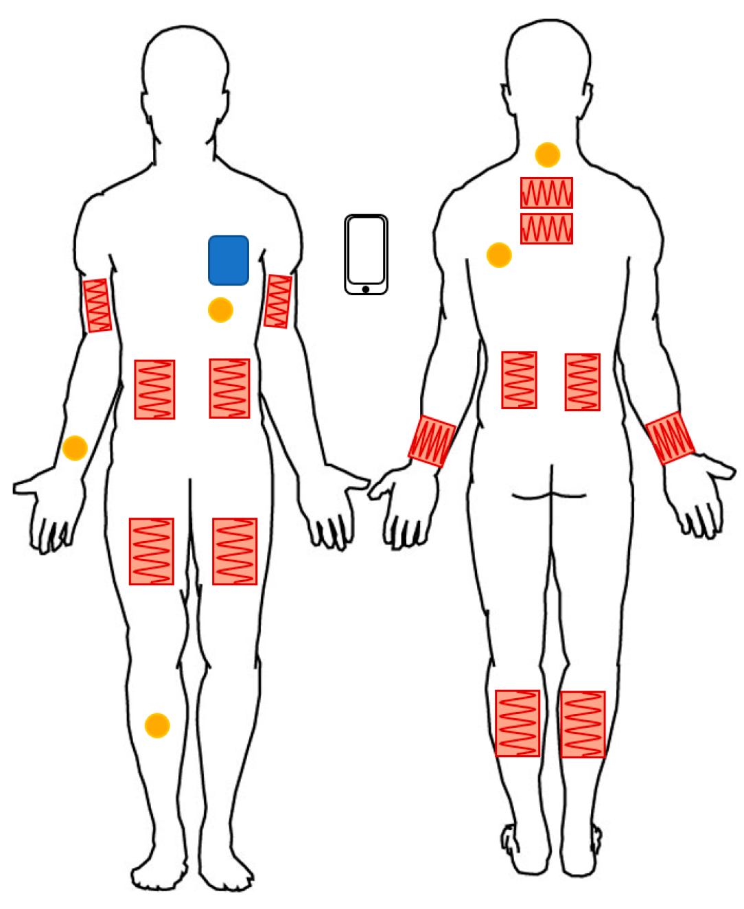
3.4. Electrically Heated Clothing

The ultimate objective of the research is to develop a set of professional-use clothing, consisting of (in one of the possible setups) a windproof Gore-Tex jacket, windproof trousers and an inner jumpsuit with integrated heating insets. The clothing design and production are the responsibility of PSA Małachowski, highly specialised producers of winter outerwear in Poland.
The heating insets are the effectors of the system, and therefore they are its most crucial part. In the course of the project development different materials have been considered for the heated insets (carbon fiber conductive sewing thread, steel heating wire, sputtering of conductors). Finally, the insets are manufactured using steel heating wire, sewn into the fabric. Separate insets are placed on the upper back, lower back, abdomen, hands, thighs and shins. The insets are controlled using the embedded system described in Section 3.5. The total power of the insets available in the tested version of the clothing prototype was 100 W. Placement of system components in the suit is presented in Figure 1. The placement of the heating insets is determined by two reasons. On the one hand, there were opinions of end users (mountain rescuers) describing what parts of the body, in their opinion, are particularly exposed to cold (some emphasized the importance of heating the central parts of the body, others complained that their hands and legs were rather cold during the rescue actions). On the other hand, the location of the heaters depended on the technical characteristics of the clothing itself:
  • the heated garment should be a single piece of clothing, so attaching heated gloves or socks was not possible,
  • heaters could not be installed on chest and arms, as the rescuers install various electronic equipment in these places,
  • the jumpsuit should fasten with zipper on the chest,
  • the heaters could not hinder sitting down and squatting.
The functionality of the clothing is not limited to the manual control of the insets—in order to provide automatic control a set of sensors is embedded into the clothing. In the experiment temperatures and humidities were recorded. However, preliminary work has shown that in this research we should focus solely on the temperature measurements. As the research presented in this article did not make use of the remainder of the sensors, the reader is referred to [25] for details.

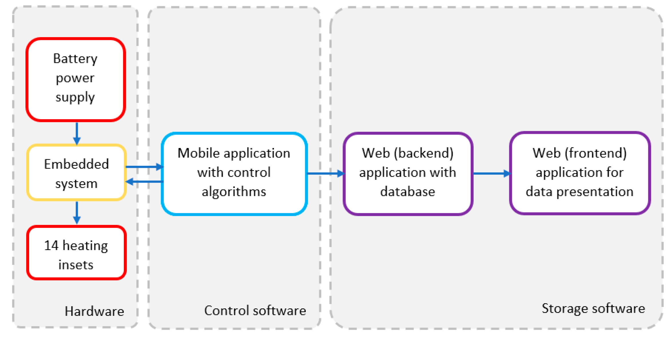
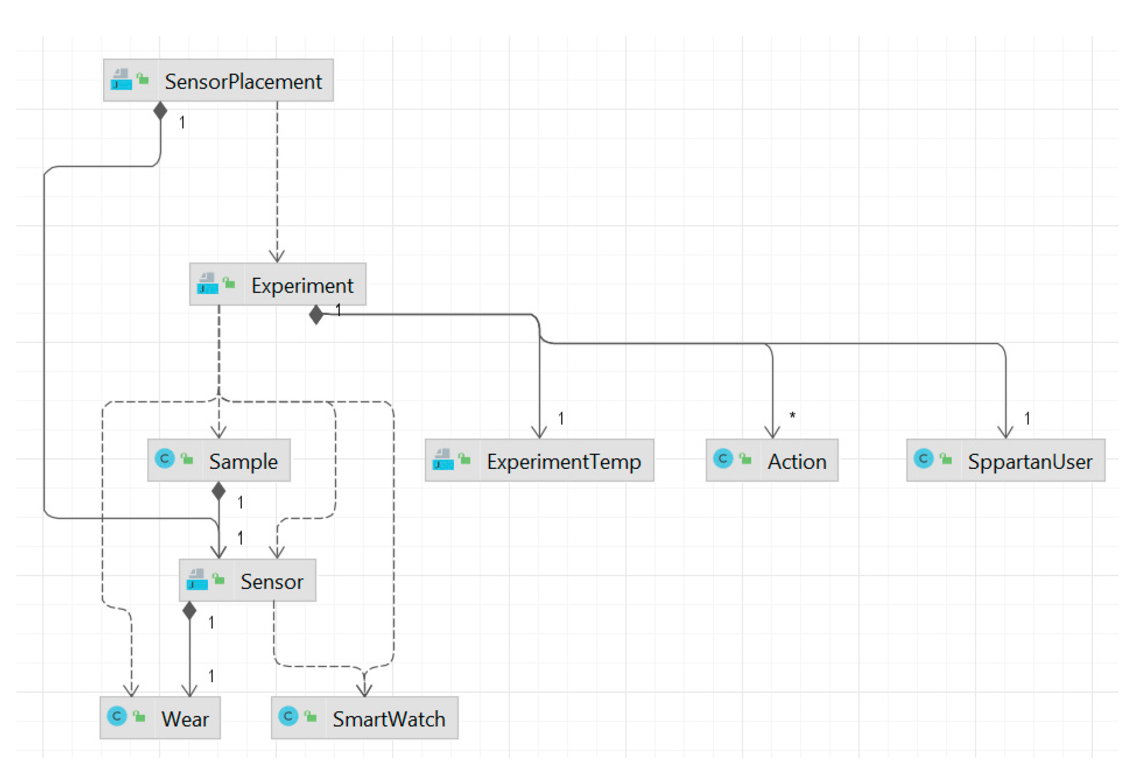
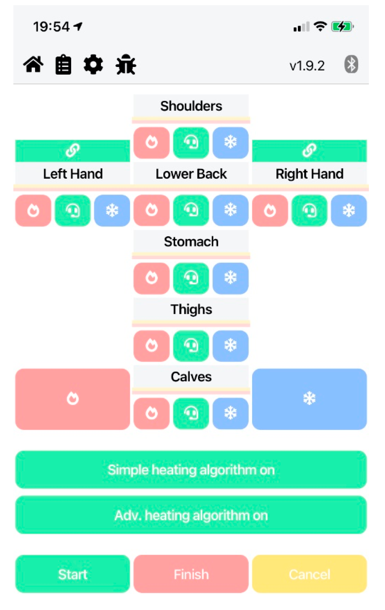
3.5. Power Supply and Control System

The control over the heating insets is possible thanks to a solution consisting of a dedicated embedded system and an application, running on an Android or iOS smartphone. The block diagram of the system is presented in Figure 2. The link between the embedded system and the smartphone is established through Bluetooth Low Energy. Power-wise, the most important task of the embedded system is first to transform the battery voltage into operating voltage, using a high-efficiency DC-to-DC converter, and then to distribute energy among the heating insets, using pulse width modulation to control heating levels.
The smartphone application was designed primarily to allow the user to control the heating levels, however, as the clothing solution is still in the development phase, it also contains a number of additional functionalities, including selection of the automatic control algorithm and the ability to send data collected from sensors to the backend web application. This allows the authors to analyse the recorded data from test experiments, which later leads to further system improvements. Communication between web application and the mobile application takes place via the rest API and with users via the website. The application has been designed in the client-server architecture with the use of standard open-source technologies. PostgreSQL [26] was chosen as the database engine. The data access layer was implemented in Hibernate [27], the server part in Spring Framework [28] and the client part in vue.js [29]. The data model is presented in Figure 3.
The screenshot of the mobile application is presented in Figure 4; the reader is referred to [30] for more details.

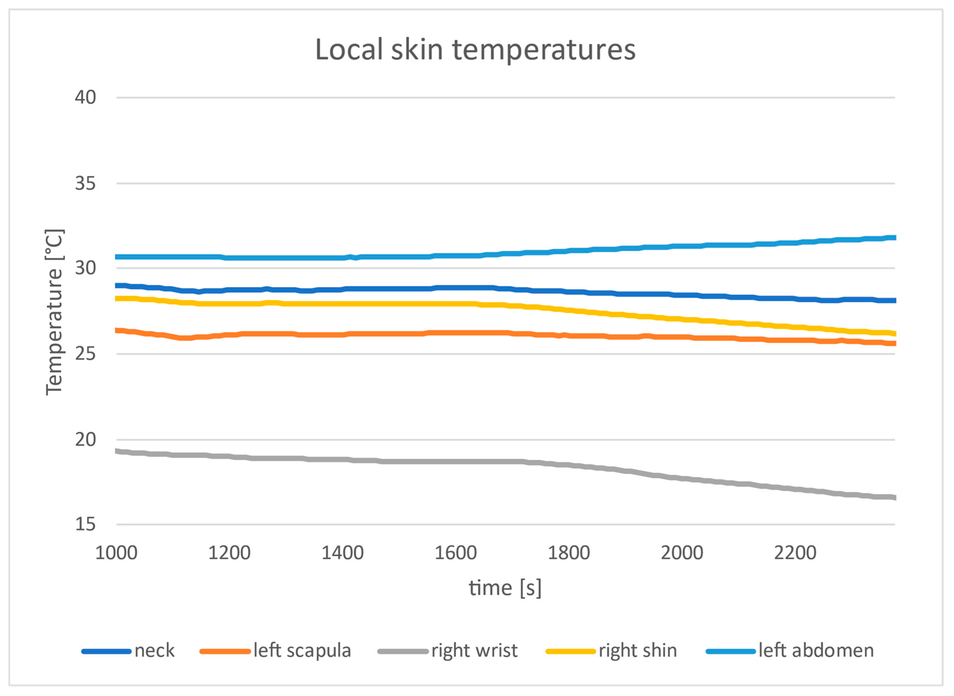
3.6. Ambient and Skin Temperature Measurements

The skin temperature was measured using a set of five Maxim Integrated iButton sensors (model DS1923, Figure 5) placed directly on the skin, affixed using strips of adhesive tape. The sensors were placed on the neck, left scapula, left abdomen, right wrist and right shin. The accuracy of the temperature readings was ±0.5 °C, and the data were collected with resolution of 0.0625 °C (11-bit). The sensors do not support continuous data transmissions, so the recorded measurements were saved in a protected memory section of sensors and had to be read after conclusion of the experiment.

3.7. Experiment

Three participants took part in the experiment and their characteristics are presented in Table 1. In the experiment conducted independently for each of them, they entered the freezing chamber and waited till distinct sensation of cold was felt in all body parts. Then they were asked to adjust, via smartphone application, the heating levels of the insets so that thermal comfort was achieved (or report that it was not possible to achieve such). The participants remained stationary at all times. In all cases the experiments lasted around 2400 s and thermal comfort was reached. Informed consent was obtained from all participants involved in the study.

4. Results

4.1. Computations Pursuant to ISO 11079

The input values for computations are gathered in Table 2 and Table 3. The thermal insulation of the clothing ensemble was calculated using the method stipulated by the ISO 9920 standard [31]. The standard provides two equations for computation of ensemble insulation based on insulation of individual items: empirical (2) and simplified (3).
I c l = 0.161 + 0.835 I c l u
I c l = I c l u ,
where Icl—basic thermal insulation of the clothing ensemble, Iclu—effective thermal insulation of the clothing ensemble units. In the discussed case most of the insulation comes from the tested clothing prototype, for which an exact value was obtained using thermal manikin, and which by itself constitutes a clothing ensemble. As the empirical equation applies to a situation where single individual items are considered, it is not appropriate in the discussed situation; consequently, the simplified one was used. The insulation value was taken from the manikin measurements described in Section 3.2 and supplemented by the typical values for other donned clothing items (e.g., boots, cap), as given in [12]—see Table 2.
The air temperature was set according to the measurements. The radiant temperature was assumed to be equal to the air temperature, which is usually a good approximation [32]. Air velocity was set at 0.4 m/s, lowest acceptable by the ISO 11079 standard. The resulting required heating power was determined by computing the total threshold required power for thermal comfort, then subtracting the metabolic energy production at rest (65 W/m2 according to the standard), and finally adjusting for the body surface area—see Table 3. The body surface area was computed using DuBois Formula (4) [33]
A = 0.202 W0.425H0.725,
where: W—weight in kg, H—height in m. This formula offers only a crude approximation of the body surface area, as it does not take into account variations of body shape attributed to sex, age, Body Mass Index (BMI), etc. However, as all the participants were males of similar age and BMI, this limitation is acceptable.

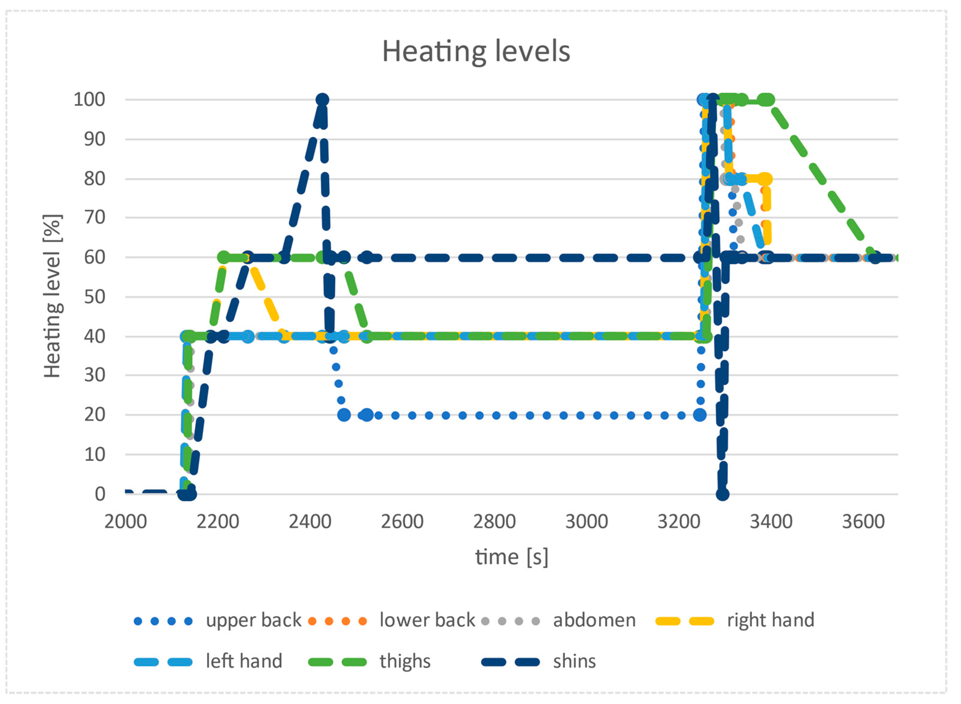
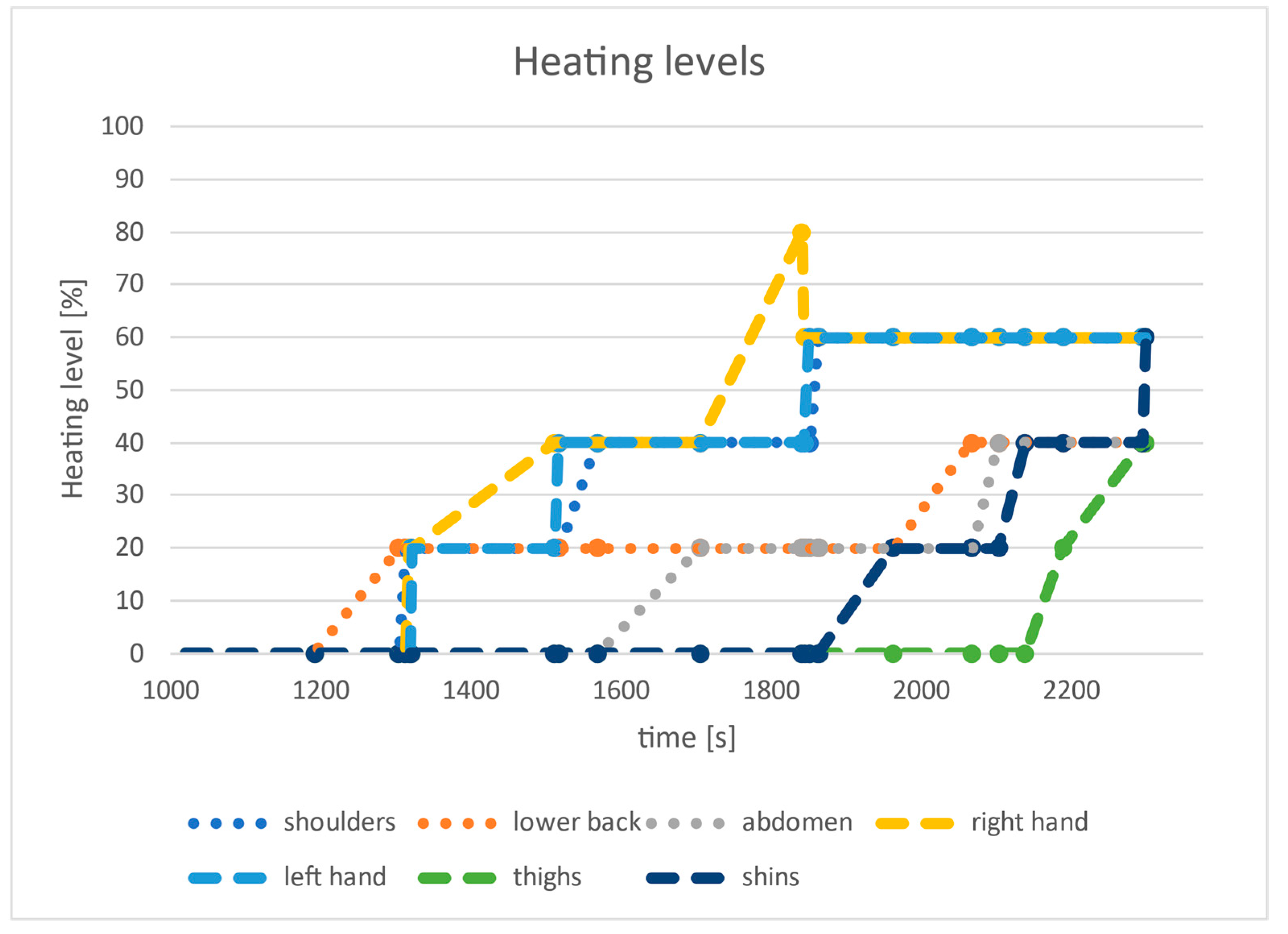
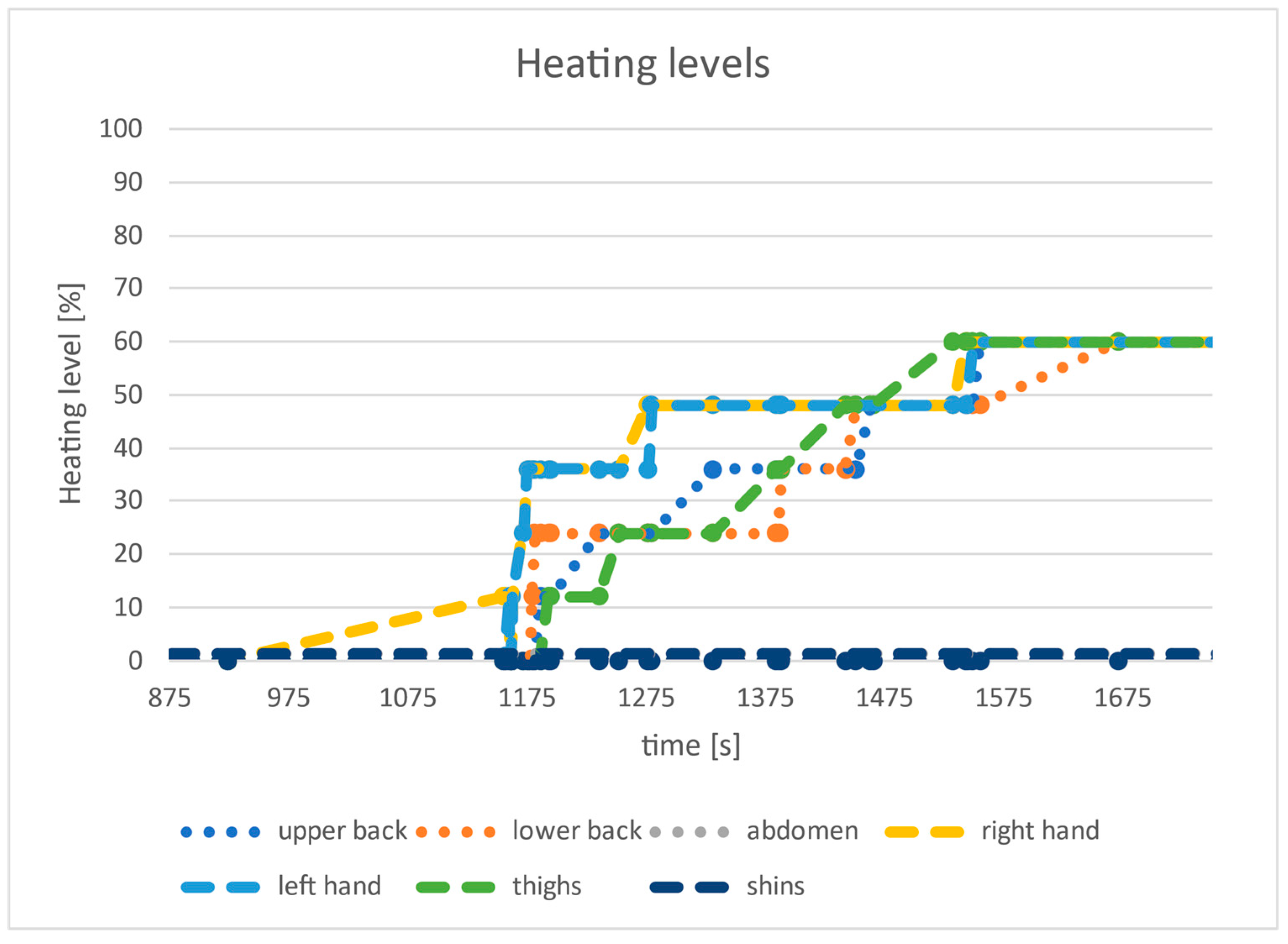
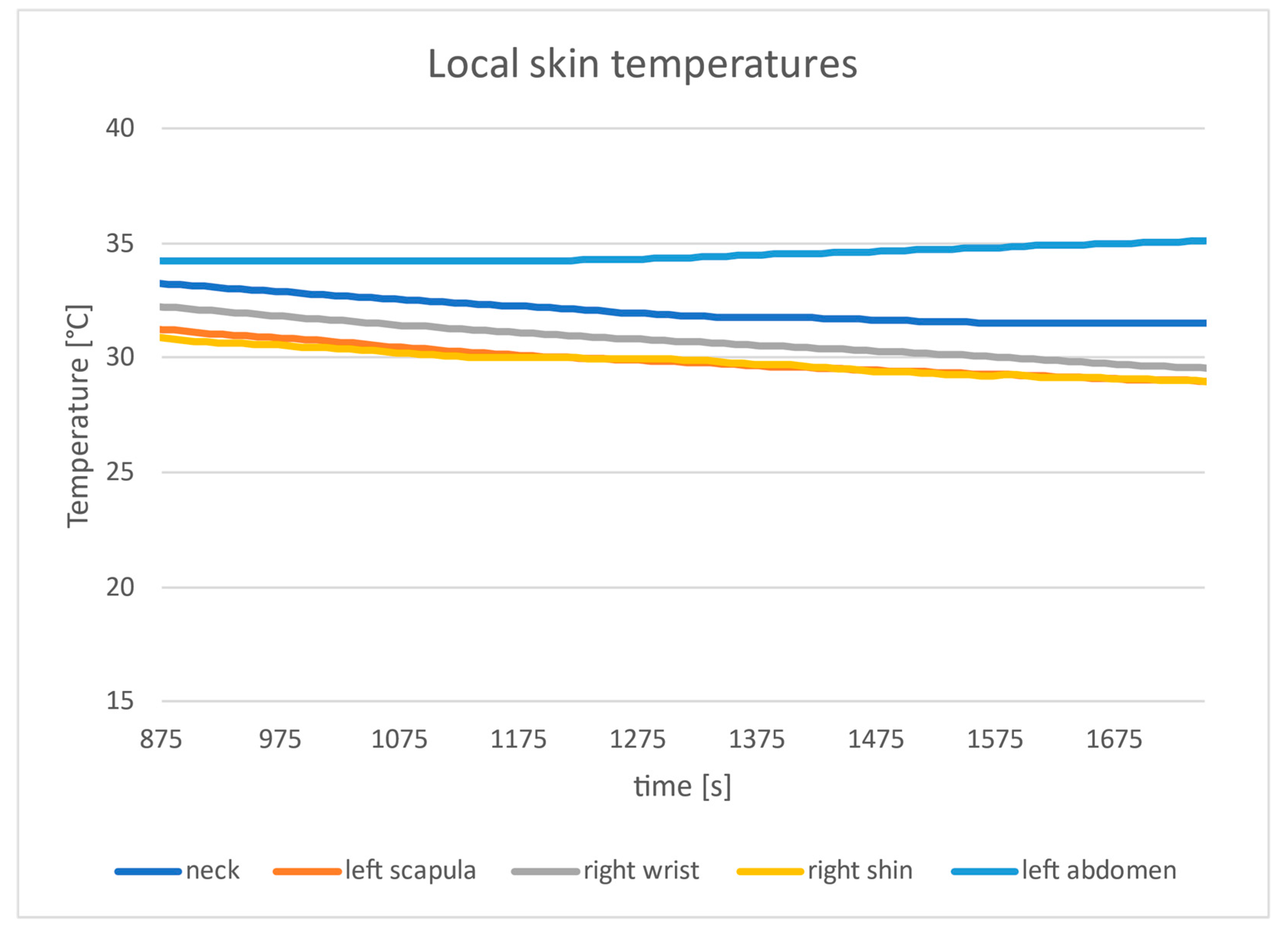
4.2. Experimental Results

The results for three participants are presented in Table 4 (in watts), while plot of heating levels for each participant are presented in Figure 6, Figure 7 and Figure 8 (in % of the nominal power of each inset, which is equal to 14.29 W).
The local skin temperature measurements are presented in Table 5. The presented values are for the moment when the participants reported reaching the state of thermal comfort.

5. Discussion

5.1. Theoretical vs. Experimental Values

There is a big discrepancy between the required power computed using the ISO 11079 standard and the values obtained experimentally: depending on the participant the experimental values are only 40–60% of the theoretical ones. There may be a number of reasons for this discrepancy:
  • The participants remained in the chamber for a relatively short period of time, up to 60 min. It is possible that longer exposure would require increasing the heating power in order to maintain thermal comfort
  • The computations using the ISO 11079 standard treat the power as generated through metabolic processes, which happens (to various extent) in all cells of the body. This means the heat is produced “inside” the body. On the other hand, when using the electrically heated garment, the heat is produced outside and close to the skin. Thermoreceptors are located in various parts of the body, but a significant number is located in the skin. Consequently, direct heating of the skin may result in false sensation of thermal comfort, while in fact the body is not in thermal balance and is losing heat.
  • The standard assumes that the skin temperature at thermal comfort is given by (5)
tsk = 35.7 − 0.0285 M,
where M—metabolic rate. At rest, with metabolic heat production of 65 W/m2, this formula gives 33.85 °C. As can be seen in Table 5, in the experiment most of the temperature readings were significantly lower. It indicates that, although the participants reported thermal comfort, the actual heat level of the body might be significantly lowered. It is also worth noting that the sensor readings are hardly affected by the power delivered to the heating insets: the temperature curves in Figure 9, Figure 10 and Figure 11 are virtually unaffected by the changing heating levels. Again, this suggests that local (intensive) heating of the skin may lead to sensation of thermal comfort, even though most of the skin surface has relatively low temperature.

5.2. Global vs. Local Comfort

Although all the participants claimed they achieved thermal comfort, this statement applied only to the body parts covered by the electrically heated jumpsuit. At the same time, all participants reported lack of thermal comfort in hands and feet—the garments used for these body parts had insufficient thermal insulation. This observation means that the participants were not in an overall thermal comfort, which further explains discrepancies in theoretical vs. observed power.

5.3. Automatic Computation of Heating Power

While during the experiment the participants manually adjusted the heating levels, it would be beneficial to make this task automatic. As the only readily available process variable describing the thermal state of the body is the skin temperature, it is straightforward to select it as a basis for the automatic control. However, the most obvious closed-loop approach, i.e., based on the error signal: the difference between the desired and actual value of this temperature, cannot be used. This is because, as this experiment shows, the controlled variable (power) does not influence the error signal. On the other hand, mounting the temperature sensor directly beneath the heating inset also does not solve the problem: as determined in a separate experiment, in such configurations the temperature readout reflects the temperature of the inset rather than the temperature of the skin.
Nonetheless, skin temperature could be used in an open-loop approach. In order to determine whether it is possible to tie in a physically-meaningful way this temperature with the required power, the authors proposed a simple model fulfilling the following requirements:
  • The difference between the measured and comfort skin temperature should be considered;
  • The heating power should be linearly dependent on this difference;
  • Body dimensions should be taken into account.
Impact of the information about clothing insulation could also be tested. However, using this value in the algorithm is debatable, as it may not be known to the user of the clothes. In the discussed model it was not included, as the total clothing insulations for all participants were similar (see Table 2).
The formula in question is given by (6)
P = (ts + tc) × Db x,
where ts—mean skin temperature, tc—comfort temperature, Db—body dimensions coefficient, x—scaling constant and P—electrical power required for comfort. For Db, the authors used skin area or body mass (both approaches were tested). Of interest is whether the scaling constant x could be set to the same value for all participants of the experiment.
As in this preliminary evaluation a single equation is to be used for the whole body, a question arises of how to compute the whole-body skin temperature. This is generally computed as a linear combination of skin temperatures at various points; a number of approaches exist, which differ by the number and location of sensors. The placement of the sensors during the experiment was close to the ISO 4-point layout, the only exception being the sensor placed on the wrist instead of the back of the hand. An additional approach, disregarding the wrist sensor, was also tested. The rationale behind this modification is the very low hand temperature for participants A and B, which was not reflected in participant C. The authors argued that for participants A and B this could be caused by imperfect tightening of the outer jacket sleeve wrist strap, which allowed air exchange, making the reading unreliable.
For the ISO 4-point approach the linear combination coefficients were 0.28, 0.28, 0.16 and 0.28, respectively, as stipulated by ISO 9886 [34], while for the second they were all set at 1/3.
Finally, it should be noted that the employed approaches provide only rough estimate, as in the cold environment the ISO 9886 standard requires temperature measurements in eight points.
Table 6 presents the mean skin temperature for both approaches, while Table 7 gives the obtained values of the scaling constant, x.
The obtained results indicate that even among only three persons it is impossible to set a common scaling coefficient. Smallest variability is observed in case of the modified ISO temperature measurements and body mass, but even in this case the ratio between the largest and the smallest value is 1.45. Even considering different underwear used by the participants, the difference is huge.

6. Conclusions

Experimental verification of the heating power computed using the ISO 11079 standard in view of the electrically heated garment design has been performed. Data were obtained from three subjects wearing electrically heated jumpsuits and standing motionlessly in a freezing chamber, adjusting heating levels for thermal comfort. The power required for thermal comfort measured during the experiment was between 42.85 W and 59.99 W, depending on the participant. This power is 40 and 60% of the power computed using the ISO 11079 standard. The observed large discrepancies mean that caution should be taken when designing heated garments, as relying solely on the theoretical models and standards may lead to oversizing of the heating system. On the other hand, analysis of the experiment conditions and thermal sensations voiced by the participants indicate that subjective responses of thermal comfort may be falsified by several factors, in turn resulting in undersized system not able to provide thermal comfort and thermal safety for long exposures.
Regarding automatic computation of heating power, the study showed that the mean skin temperature by itself is not an objective determinant of the electrical power required for comfort. The observed differences between the three participants mean that it is impossible to apply a method based on a rigid, always the same formula or procedure when only skin temperatures are used as inputs. In the opinion of authors, the only sensible approach is based on real-time control of heated clothing where sensor data are used in conjunction with individual user preferences. Preliminary tests show that the promising solution seems to be artificial intelligence (AI) techniques: initially, the heated clothing is controlled manually by the user, but the AI module gradually learns the user preferences and subsequently provide automatic, individualized control of heating insets. Further experiments are required to find out whether such an approach can reliably determine the required power.

Author Contributions

Conceptualization, W.T., R.K. and M.K.; Data curation, W.T. and R.K.; Formal analysis, W.T.; Investigation, W.T., R.K.; Methodology, W.T., R.K., A.D. and M.M.; Software, M.K.; Validation, W.T. and R.K.; Visualization, W.T. and R.K.; Writing—original draft, W.T.; Writing—review & editing, R.K., M.K., A.D. and M.M. All authors have read and agreed to the published version of the manuscript.

Funding

This work was supported by the Project “Personalized Protective Thermally Active clothing” from The National Centre for Research and Development under Grant POIR.04.01.04-00-0070/18.

Data Availability Statement

Data from the experiments are not publicly available due to foreseen commercial exploitation of the project’s results.

Conflicts of Interest

The authors declare no conflict of interest. The funders had no role in the design of the study; in the collection, analyses, or interpretation of data; in the writing of the manuscript, or in the decision to publish the results.

References

  1. ISO 11079:2007; Ergonomics of the Thermal Environment—Determination and Interpretation of Cold Stress When Using Required Clothing Insulation (IREQ) and Local Cooling Effects. ISO: Geneva, Switzerland, 2007. Available online: https://www.iso.org/standard/38900.html (accessed on 25 July 2022).
  2. Tylman, W.; Kotas, R.; Kaminski, M.; Dabrowska, A.; Mlynarczyk, M. Experimental verification of the required power for electrically heated clothing. In Proceedings of the 2022 29th International Conference on Mixed Design of Integrated Circuits and System, Wroclaw, Poland, 23–24 June 2022; pp. 192–195. [Google Scholar] [CrossRef]
  3. Wang, F.; Gao, C.; Kuklane, K.; Holmér, I. A Review of Technology of Personal Heating Garments. Int. J. Occup. Saf. Ergon. JOSE 2010, 16, 387–404. [Google Scholar] [CrossRef] [PubMed] [Green Version]
  4. Heated Glove Liners, Gloves, Jackets + More. ActiVHeat. Available online: https://www.activheat.com/ (accessed on 25 March 2022).
  5. Battery Heated Clothing Delivers Active Heat When You Need It. With Rechargeable Battery Technology It Is Easy to Choose between Different Heating Levels. Available online: https://heatexperience.eu/ (accessed on 25 March 2022).
  6. Heated Clothing, Heated Jackets, Heated Gloves, Heated Socks, Heated Vests. The Warming Store. Available online: https://www.thewarmingstore.com/ (accessed on 25 March 2022).
  7. Givoni, B.; Goldman, R.F. Predicting rectal temperature response to work, environment and clothing. J. Appl. Physiol. 1972, 2, 812–822. [Google Scholar] [CrossRef] [PubMed]
  8. Stolwijk, J.A.J.; Hardy, J.D. Control of Body Temperature. In Handbook of Physiology, Section 9: Reaction to Environmental Agents; American Physiological Society: Bethesda, MD, USA, 1977; pp. 45–68. [Google Scholar]
  9. Wissler, E.H. Mathematical simulation of human thermal behavior using whole body models. In Heat Transfer in Medicine and Biology; Shitzer, A., Eberhart, R.C., Eds.; Plenum: New York, NY, USA, 1985; Volume 1, pp. 325–373. [Google Scholar]
  10. Werner, L. Properties of the human thermostat: Results from mathematical and experimental analyses. In Proceedings of the International Conference on Environmental Ergonomics—IV, University of Texas, Austin, TX, USA, 1–5 October 1990. [Google Scholar]
  11. Fiala, D.; Lomas, K.J.; Stohrer, M. Dynamic simulation of human heat transfer and thermal comfort. In Proceedings of the 12th International Conference on Environmental Ergonomics, Portoroz, Slovenia, 19–24 August 2007. [Google Scholar]
  12. Parsons, K. Human Thermal Environments: The Effects of Hot, Moderate, and Cold Environments on Human Health, Comfort, and Performance, 3rd ed.; CRC Press: Boca Raton, FL, USA, 2014; ISBN 978-1-4665-9600-9. [Google Scholar]
  13. Haslam, R.A.; Parsons, K.C. Computerbased models of human responses to the thermal environments: Are their predictions accurate enough for practical use? In Thermal Physiology; Mercer, J.B., Ed.; Elsevier: Amsterdam, The Netherlands, 1989. [Google Scholar]
  14. Li, X.; Kuai, B.; Tu, X.; Tan, J.; Zhou, X. Three-dimensional analysis model of electric heating fabrics considering the skin metabolism. J. Eng. Fibers Fabr. 2021, 16, 15589250211047980. [Google Scholar] [CrossRef]
  15. Wang, F.; Lee, H. Evaluation of an Electrically Heated Vest (EHV) Using a Thermal Manikin in Cold Environments. Ann. Occup. Hyg. 2010, 54, 117–124. [Google Scholar] [CrossRef] [PubMed] [Green Version]
  16. Irzmańska, E.; Jurczyk-Kowalska, M. Assessment of the thermal effectiveness of mineral warmers for protective gloves used in cold environments. Int. J. Heat Technol. 2020, 38, 28–36. [Google Scholar] [CrossRef]
  17. Wang, L.; Tian, Y.; Kim, J.; Yin, H. The key local segments of human body for personalized heating and cooling. J. Therm. Biol. 2019, 81, 118–127. [Google Scholar] [CrossRef] [PubMed]
  18. Neves, S.F.; Couto, S.; Campos, J.B.L.M.; Mayor, T.S. Advances in the optimisation of apparel heating products: A numerical approach to study heat transport through a blanket with an embedded smart heating system. Appl. Therm. Eng. 2015, 87, 491–498. [Google Scholar] [CrossRef] [Green Version]
  19. Wu, J.-X.; Liao, Y.-C. Self-regulated thermal comfort control for wearable heating device. J. Taiwan Inst. Chem. Eng. 2021, 121, 74–80. [Google Scholar] [CrossRef]
  20. Fanger, P.O. Thermal Comfort. In Analysis and Applications in Environmental Engineering; Danish Technical Press: Copenhagen, Denmark, 1970. [Google Scholar]
  21. JAVA Applet for ISO 11079. 2008. Available online: https://www.eat.lth.se/fileadmin/eat/Termisk_miljoe/IREQ2009ver4_2.html (accessed on 25 March 2022).
  22. ISO 15831:2004; Clothing—Physiological Effects—Measurement of Thermal Insulation by Means of a Thermal Manikin. ISO: Geneva, Switzerland, 2004. Available online: https://www.iso.org/standard/28720.html (accessed on 25 July 2022).
  23. PN-EN 342:2018; Protective Clothing—Ensembles and Garments for Protection against Cold. European Committee for Standardization: Brussels, Belgium, 2018. Available online: https://sklep.pkn.pl/pn-en-342-2018-01e.html (accessed on 25 July 2022).
  24. Młynarczyk, M. Characteristics of Specialised Firefighter Clothing Used in Poland—The Thermal Parameters. Fibres Text. East. Eur. 2020, 139, 65–70. [Google Scholar] [CrossRef]
  25. Tylman, W.; Kotas, R.; Kamiński, M.; Woźniak, S.; Dąbrowska, A. Thermal Model for Processing Data from Undergarment Sensors in Automatic Control of Actively Heated Clothing. Energies 2022, 15, 169. [Google Scholar] [CrossRef]
  26. PostgreSQL: The World’s Most Advanced Open Source Relational Database. Available online: https://www.postgresql.org/ (accessed on 25 July 2022).
  27. Hibernate. Available online: https://hibernate.org/ (accessed on 25 July 2022).
  28. Spring Framework. Available online: https://spring.io/ (accessed on 25 July 2022).
  29. The Progressive JavaScript Framework. Available online: https://vuejs.org/ (accessed on 25 July 2022).
  30. Kotas, R.; Kamiński, M.; Tylman, W.; Woźniak, S.; Wojtera, M.; Dąbrowska, A. Comprehensive Information System for Management of Personalized Protective Thermally Active Clothing. In Proceeding of the 2021 28th International Conference on Mixed Design of Integrated Circuits and System, Lodz, Poland, 24–26 June 2021; pp. 274–279. [Google Scholar] [CrossRef]
  31. ISO 9920:2007; Ergonomics of the Thermal Environment—Estimation of Thermal Insulation and Water Vapour Resistance of a Clothing Ensemble. ISO: Geneva, Switzerland, 2007. Available online: https://www.iso.org/standard/39257.html (accessed on 25 July 2022).
  32. MDawe, M.; Raftery, P.; Woolley, J.; Schiavon, S.; Bauman, F. Comparison of mean radiant and air temperatures in mechanically-conditioned commercial buildings from over 200,000 field and laboratory measurements. Energy Build. 2020, 206, 109582. [Google Scholar] [CrossRef]
  33. Du Bois, D.; Du Bois, E.F. A formula to estimate surface area if height and weight are known. Arch. Intern. Med. 1916, 17, 86. [Google Scholar]
  34. ISO 9886:2004; Ergonomics—Evaluation of Thermal Strain by Physiological Measurements. ISO: Geneva, Switzerland, 2004. Available online: https://www.iso.org/standard/34110.html (accessed on 25 July 2022).
Figure 1. Placement of system components in the suit—left front, right back (red rectangles—heating insets; blue rectangle—embedded system; orange circles—temperature sensors).
Energies 15 07713 g001
Figure 2. Block diagram of the system.
Energies 15 07713 g002
Figure 3. Data model—classes representation of the business model. Number 1 and asterisk indicate cardinality, diamond symbol indicates container.
Energies 15 07713 g003
Figure 4. Smartphone control application.
Energies 15 07713 g004
Figure 5. Maxim Integrated iButton DS1923 sensor.
Energies 15 07713 g005
Figure 6. Heating levels for participant A when adjusting to reach subjective thermal comfort.
Energies 15 07713 g006
Figure 7. Heating levels for participant B when adjusting to reach subjective thermal comfort.
Energies 15 07713 g007
Figure 8. Heating levels for participant C when adjusting to reach subjective thermal comfort.
Energies 15 07713 g008
Figure 9. Local skin temperatures for participant A when adjusting to reach subjective thermal comfort.
Energies 15 07713 g009
Figure 10. Local skin temperatures for participant B when adjusting to reach subjective thermal comfort.
Energies 15 07713 g010
Figure 11. Local skin temperatures for participant C when adjusting to reach subjective thermal comfort.
Energies 15 07713 g011
Table 1. Characteristics of participants.
ParameterParticipant
ABC
age364046
height1.88 m1.72 m1.79 m
weight85 kg65 kg76 kg
underwearnonethinMedium
Table 2. Thermal insulation of garments.
GarmentParticipant
ABC
tested clothing 11.27 clo1.27 clo1.27 clo
underwear 20.05 clo0.14 clo0.17 clo
boots 20.1 clo0.1 clo0.1 clo
gloves 20.05 clo0.05 clo0.05 clo
cap 20.1 clo0.1 clo0.1 clo
total 31.57 clo1.66 clo1.69 clo
1 tested on the thermal manikin; 2 as in ISO 9920; 3 estimated according to ISO 9920.
Table 3. Input data for ISO 11079 computations.
ParameterParticipant
ABC
air temperature−3 °C0 °C−3 °C
radiant temperature−3 °C0 °C−3 °C
air velocity0.4 m/s0.4 m/s0.4 m/s
clothing insulation1.57 clo1.66 clo1.69 clo
body surface area2.11 m21.76 m21.94 m2
required power, scaled 126 W/m2111 W/m2119 W/m2
electrical power, scaled61 W/m246 W/m254 W/m2
electrical power128.66 W81.22 W104.81 W
Table 4. Experimental results of heating power.
Heating InsetParticipant
ABC
upper back8.57 W8.57 W8.57 W
lower back8.57 W5.71 W8.57 W
abdomen8.57 W5.71 W8.57 W
right upper limb8.57 W8.57 W8.57 W
left upper limb8.57 W8.57 W8.57 W
thighs8.57 W5.71 W0 W
shins8.57 W5.71 W0 W
Total59.99 W48.55 W42.85 W
Table 5. Local skin temperature measurements at thermal comfort.
Sensor PlacementParticipant
ABC
neck31.63 °C28.20 °C31.52 °C
left scapula26.83 °C25.75 °C29.73 °C
left abdomen35.35 °C31.69 °C34.98 °C
right wrist20.26 °C16.77 °C29.73 °C
right shin22.69 °C26.32 °C29.09 °C
Table 6. Skin temperature measurements at thermal comfort.
Computation MethodParticipant
ABC
ISO 4-point25.96 °C25.16 °C30.05 °C
ISO 4-point w/o wrist sensor27.05 °C26.75 °C30.11 °C
Table 7. Scaling constant relating skin temperature to the heating power.
ApproachParticipant
Skin TemperatureBody DimensionABC
ISO-4 pointArea3.613.185.82
ISO-4 pointMass0.0890.0860.148
ISO 4-point w/o hand sensorArea4.183.895.91
ISO 4-point w/o hand sensorMass0.1040.1050.151
Publisher’s Note: MDPI stays neutral with regard to jurisdictional claims in published maps and institutional affiliations.

