Article

A Reduced Reaction Mechanism for Diesel/2-Methyltetrahydrofuran Dual-Fuel Engine Application

1
School of Mechanical Engineering, Anyang Institute of Technology, Anyang 455000, China
2
Anyang Key Laboratory of Advanced Aeronautical Materials and Processing Technology, Anyang Institute of Technology, Anyang 455000, China
3
School of Mechanical and Electronic Engineering, Shandong Agricultural University, Taian 271018, China
*
Author to whom correspondence should be addressed.
Energies 2022, 15(20), 7677; https://doi.org/10.3390/en15207677
Submission received: 20 September 2022 / Revised: 9 October 2022 / Accepted: 12 October 2022 / Published: 18 October 2022

Abstract

:
2-methyltetrahydrofuran (MTHF2) has been recently regarded as a promising alternative engine fuel. However, the chemical reaction mechanism for MTHF2 combustion in the engine has not been reported to date. In this study, a reduced diesel/MTHF2 reaction mechanism with only 78 species among 233 reactions was constructed for diesel/MTHF2 dual-fuel engine simulations. Firstly, a diesel surrogate mechanism involving the sub-mechanisms of n-decane, iso-octane, methylcyclohexane (MCH), toluene, a reduced mechanism of C2-C3 species and a detailed mechanism of H2/CO/C1 was selected. Secondly, a skeletal MTHF2 mechanism containing 54 species and 294 reactions was formulated under engine-relevant conditions using combined mechanism reduction methods. Thirdly, a reduced sub-mechanism of MTHF2 oxidation with 11 species and 13 reactions was extracted and combined with the four-component diesel surrogate fuel mechanism. Subsequently, the reduced diesel/MTHF2 mechanism was obtained by improving the combined five-component mechanism based on sensitivity analysis. Finally, the proposed mechanism was validated with selected experimental data of ignition delay times, flame species concentrations and laminar flame speeds. In addition, the new measurements from diesel/MTHF2 dual-fuel engine combustion were obtained and then utilized to further assess the developed mechanism. Overall, the developed diesel/MTHF2 mechanism can be used for diesel and MTHF2 dual-fuel engine combustion simulation.

1. Introduction

Greenhouse gas emissions from the transportation sector contribute to anthropogenic climate change. The application of alternative fuels is an efficient strategy to reduce CO2 emissions from transportation facilities. Among various alternative fuels, saturated and unsaturated cyclic ethers have recently received a lot of attention due to their renewable and eco-friendly properties [1,2,3,4,5]. 2-methyltetrahydrofuran (MTHF2), as a representative example of saturated furans, has the potential to improve the combustion of internal combustion engines (ICEs) owing to its oxygenated nature. Large-scale production of MTHF2 from cellulosic biomass carbohydrates can be achieved via the processes of catalytic and pyrolytic [6,7]. Moreover, the lower heating value (LHV) of MTHF2 (32.7 MJ/L) is similar to that of gasoline (~31.6 MJ/L) [8]. With the above-mentioned merits, MTHF2 has been proposed as a favorable alternative transportation fuel.
The application of MTHF2 fuel in practical ICEs has been experimentally investigated recently. Rudolph and Thomas [9] reported that a gasoline/MTHF2 blend containing 10% MTHF2 could produce similar engine emissions and performance compared to pure gasoline. Comparisons were also conducted by Lucas et al. [10] when a SI engine using pure gasoline and gasoline/MTHF2 blend, and the comparisons demonstrated that gasoline/MTHF2 blend with 60% MTHF2 in volume had the advantage in lessening hydrocarbon (HC), carbon monoxide (CO) and benzene emissions compared to gasoline but raised nitrogen oxides (NOx) emission slightly. The experiments of Thewes et al. [11] found that MTHF2 combustion yields lower emission levels of HC and particulate matter (PM) compared to gasoline, while a similar NOx emission level was produced. Janssen et al. [12] concluded that PM emission could be almost entirely reduced when a diesel engine used a blend of 70% MTHF2 and 30% di-n-butylether by volume. The pre-ignition characteristics of a SI optical engine using gasoline, ethanol, MTHF2 and 2-methylfuran were explored by Hülser et al. [13]. Their results indicated that the overall ignition tendencies of gasoline, MTHF2 and 2-methylfuran corresponded well to the octane ratings.
In order to deeply explore the pyrolysis and oxidation characteristics of MTHF2, substantial advanced fundamental research has also been performed to date. Moshammer et al. [14] established a detailed MTHF2 mechanism that included 185 species among 1412 reactions. This mechanism was validated by comparing their measured species concentration profiles from a low-pressure (40 mbar) premixed MTHF2 flame. Furthermore, it was taken to study the ignition characteristic of MTHF2 by Wang et al. [15], who reported that this mechanism satisfactorily reproduces the experimental shock tube (ST) ignition delay times (IDTs) under high-temperature conditions. The pyrolysis products, premixed flame structure and laminar flame speeds (LFSs) for MTHF2 were experimentally studied by Bruycker et al. [16] at various operating conditions. The authors also proposed a detailed mechanism for MTHF2 oxidation and pyrolysis, which could satisfactorily reproduce the experimental data of speciation profiles and LFSs. Tripathi et al. [17] determined the IDTs of MTHF2 at 10–40 atm with equivalence ratios (φ) of 0.5, 1.0 and 2.0 by utilizing a high-pressure ST (HPST) and a rapid compression machine (RCM). Meanwhile, they built a detailed mechanism with 250 species and 2494 reactions, and the experimental IDTs and flame species concentrations were used to evaluate its performance. The IDTs of stoichiometric MTHF2/oxygen (O2)/inert mixtures in the pressure range 0.3–2.1 MPa were measured by Fenard et al. [18]. In addition, they proposed a detailed MTHF2 oxidation mechanism with 507 species and 2425 reactions. The measurements of IDTs and flame speciation data were taken to evaluate this mechanism. A detailed MTHF2 oxidation model consisting of 282 species among 1712 reactions was built by Wang et al. [19] from the mechanism of Moshammer et al. [14]. They validated this mechanism by employing their experimental IDT data covering an overall temperature range of 1050–1800 K, φ = 0.5–2.0 for pressures ranging from 1.2 to 10 atm. Recently, Wang and his co-workers [20] built a detailed high-temperature oxidation model for the MTHF2/iso-octane mixture, and the performance of the detailed mechanism was evaluated against measured LFS, IDT and laminar flame structure. Wu et al. [21] constructed a reduced saturated furanic fuels mechanism containing 56 species and 183 reactions. The predictive performance of this mechanism was assessed by comparing the previous fundamental experimental data, but the applicability of the reduced mechanism in practical ICEs was not reported.
As stated above, the previous engine tests [9,10,11,12,13] have demonstrated that MTHF2 is a promising alternative or additive for gasoline and diesel. However, numerical studies should be conducted before the wide application of MTHF2 in practice to better realize the effects of MTHF2 fuel on engine performance. Multi-dimensional engine simulations can be performed by coupling accurate and reliable fuel chemistry with a small size. However, as far as we know, this is the first work to construct the reduced diesel/MTHF2 mechanism for engine simulation.
In this study, a mixture of n-decane, iso-octane, toluene, and methylcyclohexane (MCH) was applied as a diesel surrogate, and a reduced diesel/MTHF2 mechanism comprised of only 78 species among 233 reactions was developed. The developed mechanism was well evaluated against the measured results of ST IDTs, species concentrations from JSRs and laminar premixed burners, LFSs, and diesel/MTHF2 dual-fuel engine combustion.

2. Mechanism Development

A decoupling methodology [22,23] was utilized to construct the new reduced diesel/MTHF2 mechanism, which can yield a skeletal mechanism with compact size while the ignition and combustion characteristics can be well retained. With this methodology, reduced sub-mechanisms of different fuels’ oxidation were coupled with a reduced C2-C3 mechanism and a detailed H2/CO/C1 mechanism.

2.1. Base Diesel Surrogate Mechanism

The four-component diesel surrogate fuel model from the work of Chang and co-workers [22] was adopted as the base mechanism, and this model was constructed by applying the decoupling methodology [22,23]. As known, commercial diesel fuel is a mixture of hundreds to thousands of hydrocarbon components, and its main components can be classified as n-alkanes, iso-alkanes, cycloalkanes and aromatics [24]. Those four components in actual diesel fuel were represented by n-decane, iso-octane, MCH and toluene, respectively, in the diesel surrogate of Chang et al. [22]. And the key physicochemical parameters of diesel fuel, such as C/H ratio, LHV and aromatic content, could be reasonably captured by determining the composition of the four surrogate fuels. Moreover, the four-component mechanism has been widely validated using the measurements of shock tube IDTs, species profiles from fundamental burners, LFSs, and extinction strain rates. It has been demonstrated that an overall satisfactory match between the simulations and measurements was acquired.

2.2. The Reduced MTHF2 Mechanism

The detailed combustion kinetics model for MTHF2 developed systematically by Tripathi and his co-workers [17] was chosen for constructing the diesel/MTHF2 mechanism in the present study. As previously mentioned, this detailed mechanism compares 250 species and 2494 reactions and has been validated against measured results under engine-like conditions. The decoupled species and irrelevant reactions contained in the detailed MTHF2 mechanism were initially removed with the directed relation graph with error propagation (DRGEP) method [25,26,27,28]. This reduction process was conducted with a wide range of conditions: 1–80 bar, temperatures of 600–1600 K, and φ = 0.5, 1.0 and 2.0. IDTs of MTHF2/air mixtures were adopted as the constraint parameter, and the predicted IDT was determined as the time of temperature increasing from reflected shock temperature by 400 K. After the DRGEP reduction process, a reduced MTHF2 mechanism with 87 species among 507 reactions was acquired.
Subsequently, the obtained reduced mechanism was further downsized with the reaction path analysis (RPA) method. During this reduction stage, the RPA for MTHF2 was done under temperatures of 700 and 1500 K with a pressure of 40 bar and simulation times corresponded to 20% fuel consumption. The reactions with negligible flux path were identified and eliminated, which led to the generation of a new skeletal MTHF2 combustion model comprised of 57 species among 301 reactions. Figure 1 presents a comparison of calculated IDTs of MTHF2/air using the detailed Tripathi’s mechanism [17] and the reduced MTHF2 mechanism based on the DRGEP and RPA methods. As seen, the ignition delays calculated by the two mechanisms were quite similar at different operating conditions. This indicates that the main reaction pathway of MTHF2 was reasonably preserved in the reduced MTHF2 mechanism.
Based on the new skeletal MTHF2 mechanism, a RPA of stoichiometric MTHF2/air mixtures oxidation at low and high temperatures are depicted in Figure 2. As seen, MTHF2 was firstly consumed through H-abstraction reactions, yielding two isomers (MTHF22J and MTHF25J). The isomers for large molecule radicals can be lumped to further minimize the number of species in the generated reduced MTHF2 mechanism. It is observed that the main channel of MTHF2 consumption was H-atom abstraction to produce the MTHF25J radical; this path consumes about 67.4% and 72.7% of MTHF2 at 700 and 1500 K, respectively. Therefore, MTHF25J remained to maintain the major combustion reaction pathways of MTHF2. Due to the formation reaction of MTHF22J consuming 32.6% and 27.3% of the MTHF2 fuel at 700 and 1500 K, respectively, thus the process of isomer lumping would introduce some errors in the predictions, as seen in Figure 3, especially at the low-temperature region, the maximum induced error recorded was 93.92%, 94.97%, 95.69% and 96.05% at 10, 20, 40 and 80 bar, respectively. The errors introduced by the removal of isomers and non-essential reaction pathways can be reduced by adjusting the rate coefficients of the corresponding reactions. After the processes of mechanism reduction, a reduced mechanism for MTHF2 oxidation containing 54 species and 294 reactions was formulated.

2.3. Formation of the Reduced Diesel/MTHF2 Mechanism

As previously mentioned, the decoupling methodology [22,23] was adopted to construct the skeletal combustion chemistry of diesel/MTHF2. Therefore, based on the newly formulated reduced MTHF2 mechanism in the previous stage, the main fuel consumption reactions of MTHF2 (11 species and 13 reactions) were extracted and merged with the base diesel surrogate mechanism, and the co-oxidation or cross-reactions between various fuels were not considered. Table 1 lists the complete MTHF2 sub-mechanism. After the merge, a skeletal combined n-decane/iso-octane/MCH/toluene/MTHF2 mechanism included 78 species, and 233 reactions were obtained. As for the combined mechanism, the predictive performance of the n-decane, iso-octane, MCH and toluene sub-mechanisms were retained since the species or reactions in the base diesel surrogate mechanism were not eliminated. However, due to the processes of mechanism reduction and combination, significant deviations between the calculated ignition delays for MTHF2 using the combined mechanism and the experimental data were observed, thus improvement for the MTHF2 sub-mechanism was conducted to lessen the induced error caused by the elimination of unimportant reactions and isomers.
In order to ascertain the sensitive reactions on IDT, a sensitivity analysis was conducted for the ignition delays of stoichiometric MTHF2/air under temperatures of 600–1600 K at 10–80 bar, as exhibited in Figure 4. The sensitivity coefficient (S) is defined as: S = (τ2.01.0) − 1, where τ1.0 and τ2.0 are the original IDT and the simulated IDT with the pre-exponential factor (A) of a reaction multiplied by two, respectively. A positive value of S extends the ignition delay; thereby, the reactivity was reduced. According to the results of the sensitivity analysis, the pre-exponential factors of five important sensitive reactions related to MTHF2 were adjusted. Table 1 summarizes the modified reactions and their rate parameters.

3. Mechanism Validation

In this section, simulations were conducted by using the SENKIN, PREMIX and perfectly stirred reactor (PSR) subroutines in the CHEMKIN package [29] and KIVA-3V code [30]. The SENKIN code was employed to conduct ST IDT simulations. To simulate the laminar premixed flames, the PREMIX code was used. JSR species profiles were simulated using the PSR code. The KIVA-3V code [30] was adopted for the engine simulations.

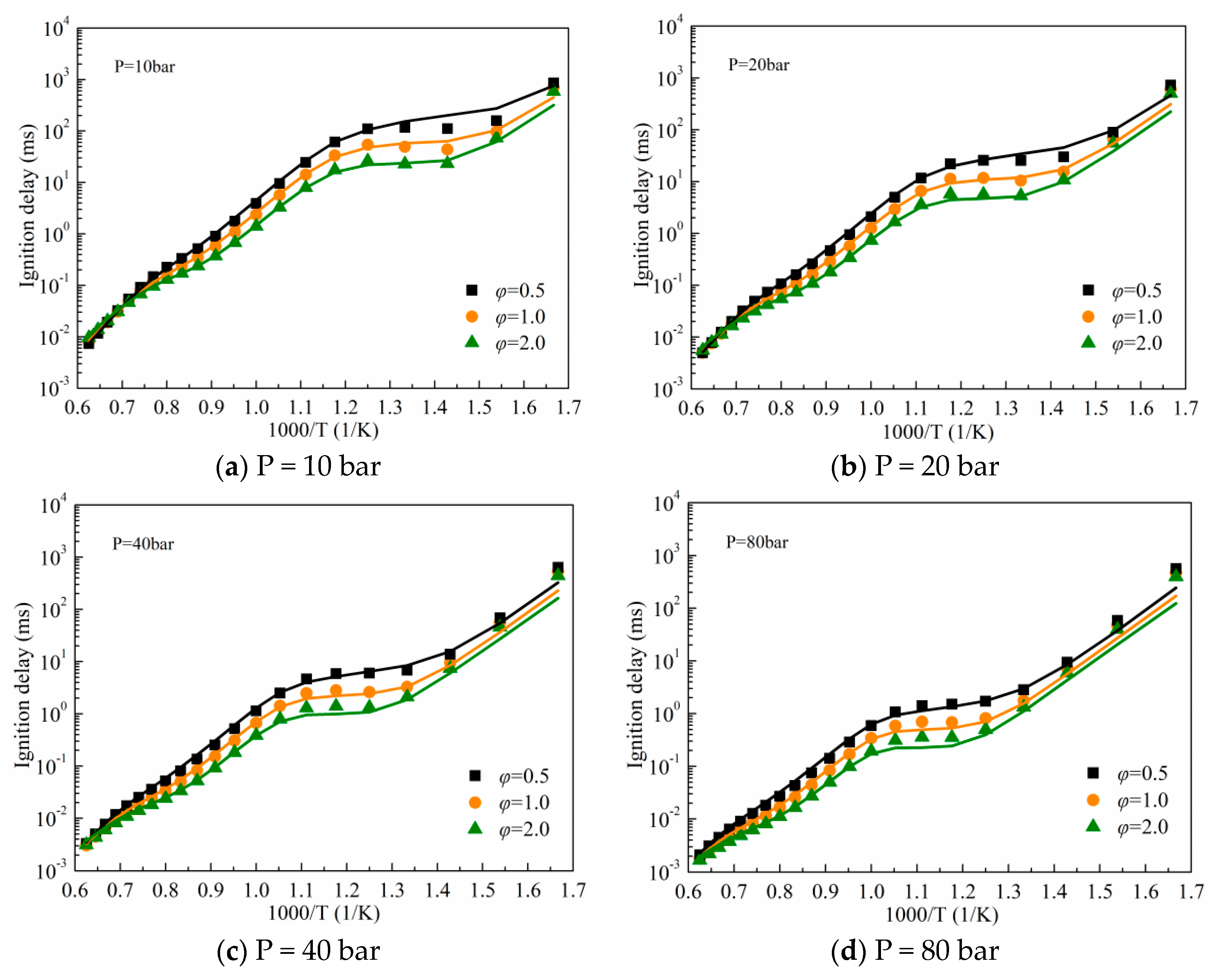
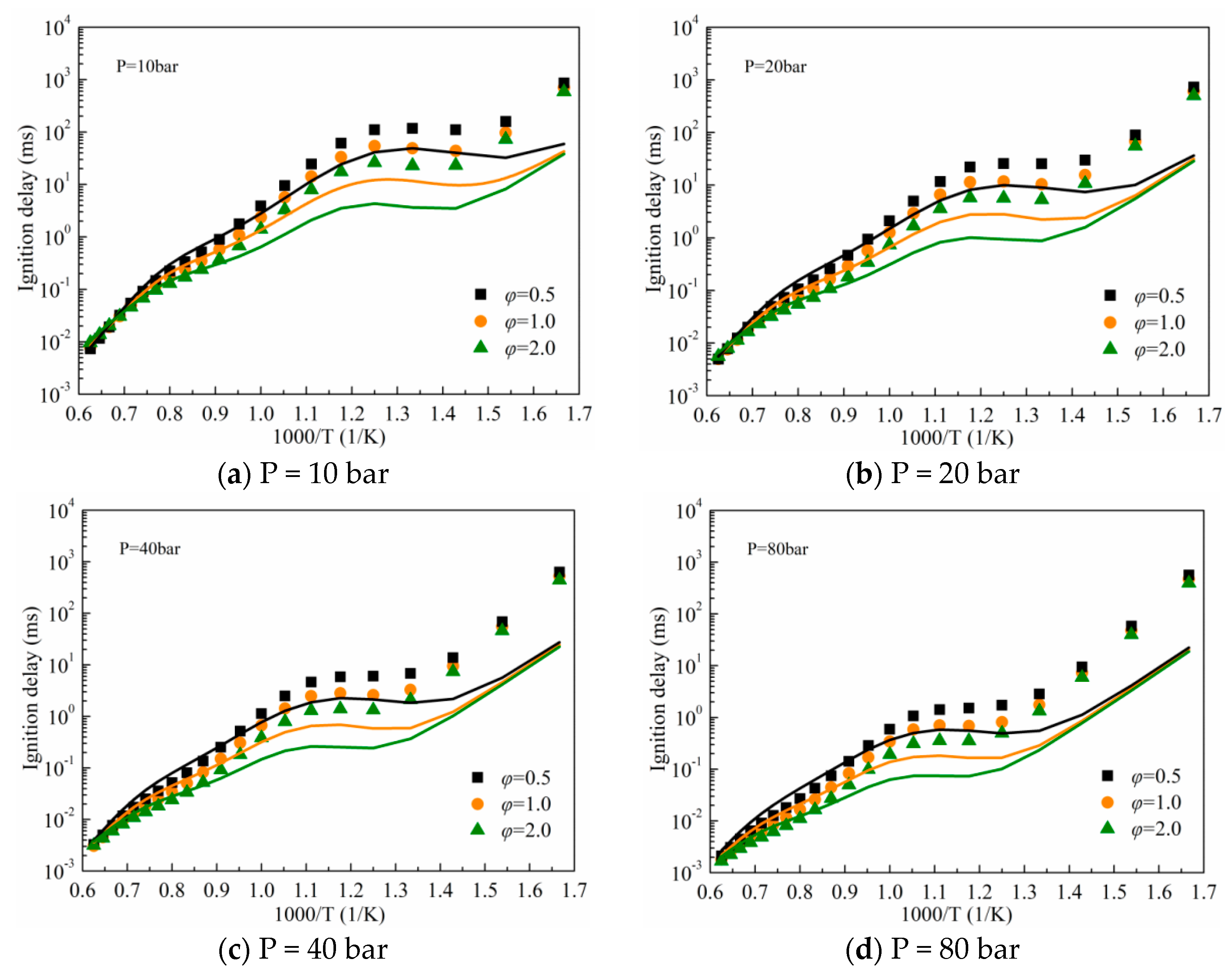
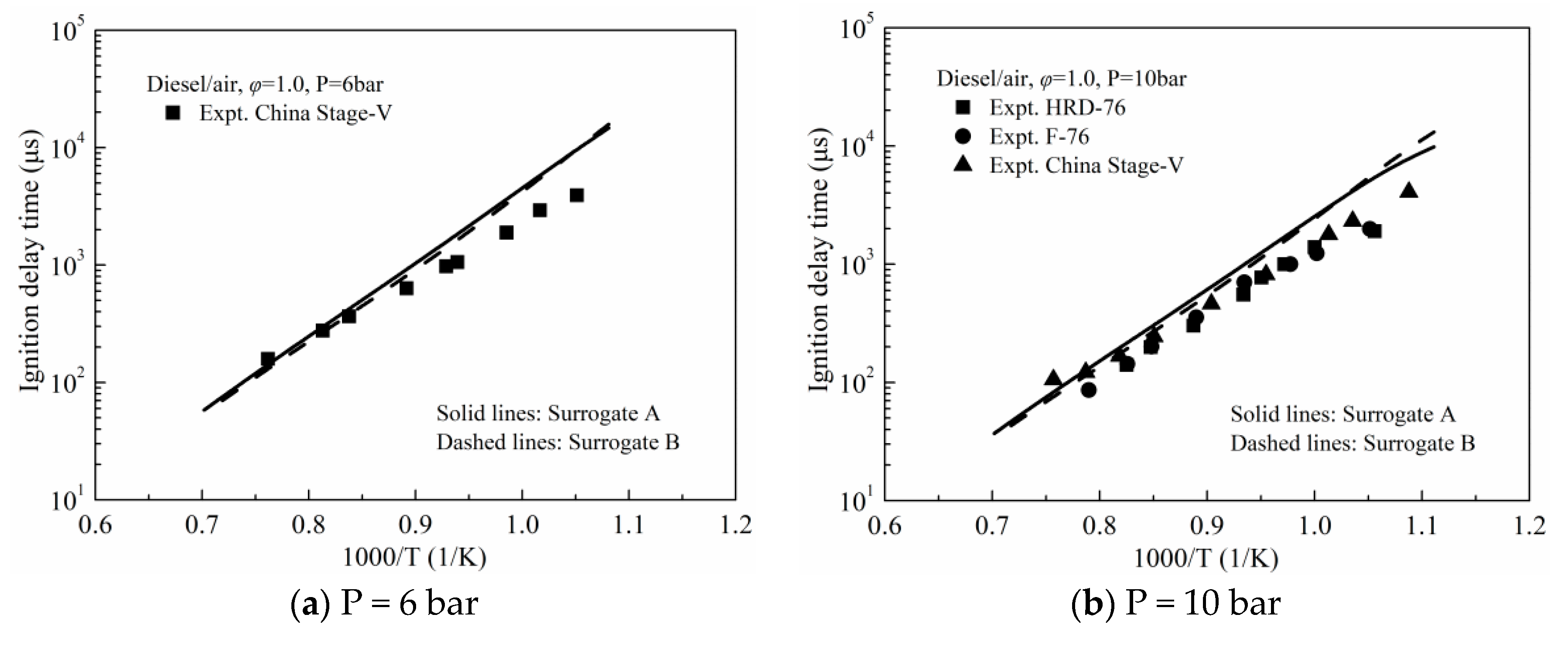
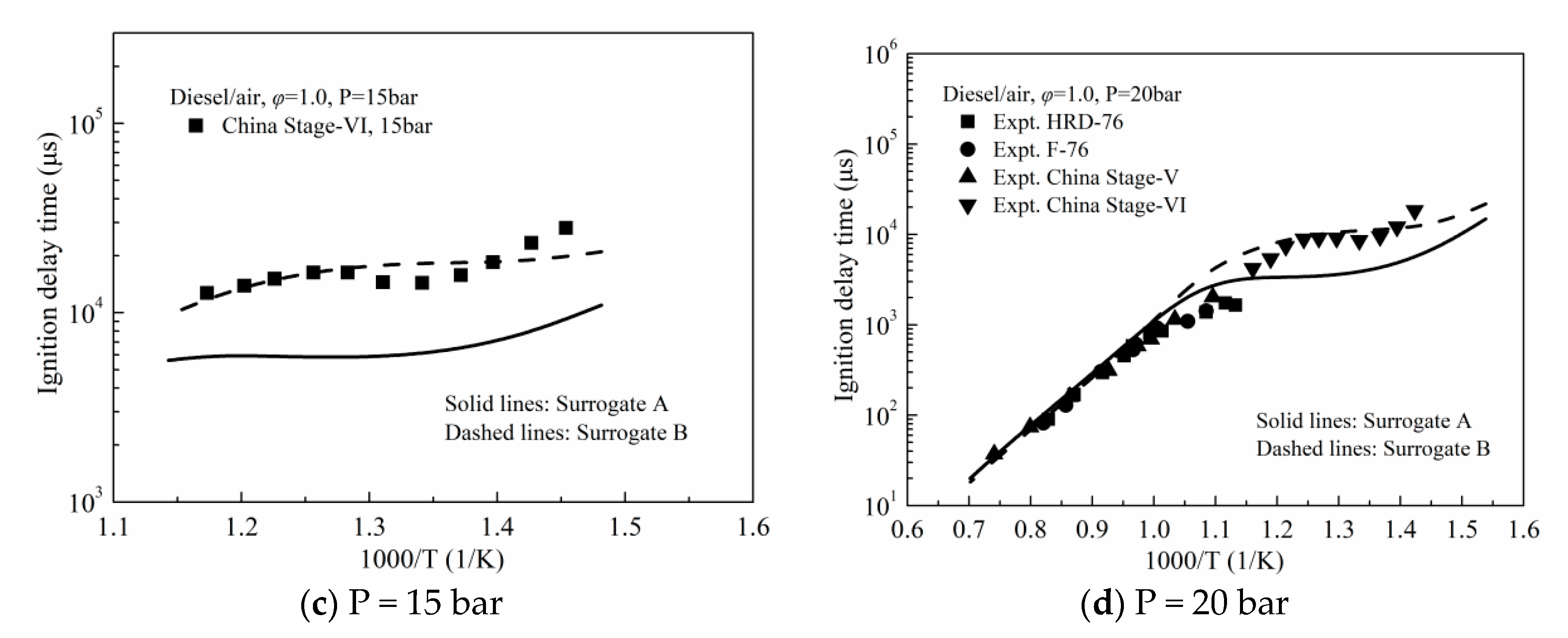
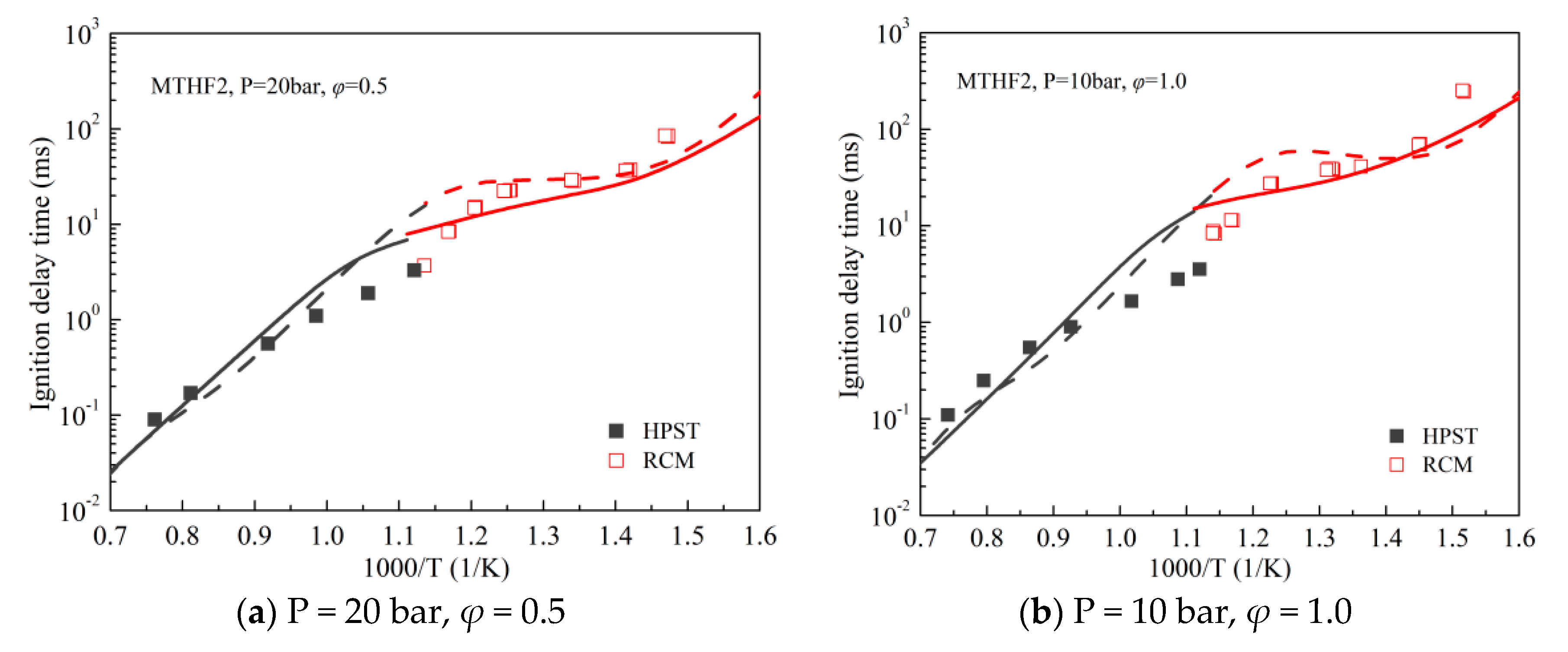
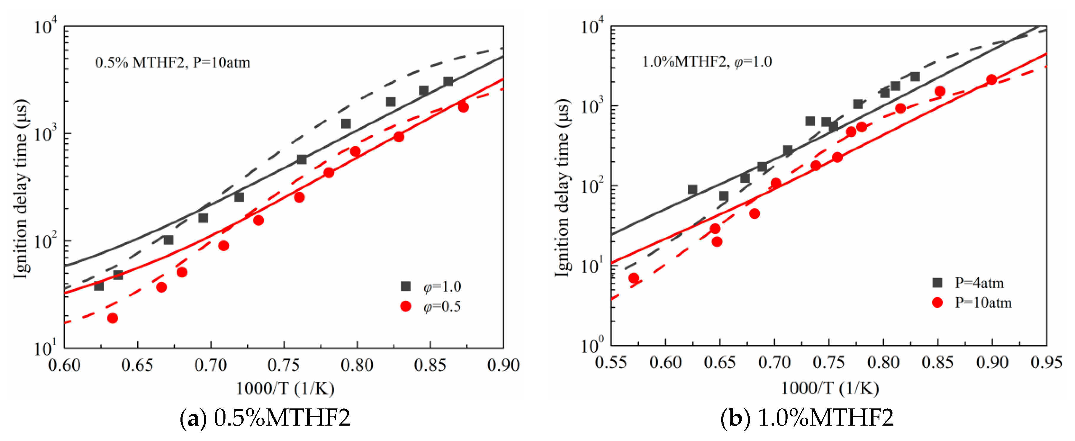
3.1. Validation against Ignition Delay Times

According to the work of Chang et al. [22], 50.39% n-decane/10.56% iso-octane/12.86% MCH/26.19% toluene (Surrogate A) and 26.67% n-decane/14.89% iso-octane/36.81% MCH/21.64% toluene (Surrogate B) were confirmed as two diesel surrogate fuels. In this section, both surrogates were employed to validate the reliability of the proposed five-component surrogate mechanism for predicting the IDTs of real diesel fuel. The calculated IDTs were compared with the experimental IDTs of F-76 diesel [31], HRD-76 diesel [31], ULSD#2 diesel [32], FD9A diesel [32], China-V diesel [33] and China-VI diesel [34], as shown in Figure 5 and Figure 6. The pressure range for validation spans the range of 6–20 bar under temperatures of 678–1371 K, which is close to diesel engine ignition and combustion conditions [35]. Generally, the experimental results were reasonably reproduced using both surrogate models, especially since the negative temperature coefficient behavior could be captured under the low-temperature condition. Some disagreement between the predictions and measurements can be primarily due to the discrepancy in component type and component content among the surrogate fuels and real diesel fuels.
In addition, the two surrogates exhibit similar IDT predictions at high temperatures beyond 900 K, but the apparent difference between the predicted IDT values of the two surrogates was observed at lower temperature conditions. As shown in Figure 6c,d, Surrogate A obviously underestimates the experimental IDTs of China-VI diesel, but surrogate B was able to well reproduce those experimental results, which indicates that the fuel component proportions have a significant impact on the ignition behavior prediction. Commercial China-VI diesel was adopted for the new dual-fuel engine experiments in this study. Thus, surrogate B was chosen as the diesel surrogate fuel in the following section.
The IDT measurements for MTHF2 in HPST and RCM by Tripathi and his co-workers [17] at pressures of 10, 20, and 40 bar, ranging temperatures of 639–1413 K and the experimental data in a ST for MTHF2 in argon (Ar)-diluted oxygen mixture by Wang et al. [19] at 4 and 10 atm from 1112 to 1752 K were used to evaluate the developed mechanism. Figure 7 and Figure 8 illustrate the comparison of the calculated IDTs using the present mechanism with the measurements, the predicted values of the detailed MTHF2 mechanism [17] are also included for reference. As shown in Figure 7, the experimental results were fairly reproduced using the two mechanisms under various pressure and temperature conditions, although some deviations between the predicted data and experiments were present. It was also observed from Figure 8 that both mechanisms could well capture the measured IDTs at various operating conditions. However, the proposed mechanism slightly over-predicts the IDTs compared to the experimental results and the predictions of the detailed mechanism [17] at temperatures beyond 1425 K. As the temperature increases to 1580 K, the proposed mechanism overestimated the IDT with a 121.05% error from experimental data at a fuel mole concentration of 0.5%, a pressure of 10 atm and φ = 0.5. Therefore, the high-temperature chemistry of MTHF2 needs to be further improved.

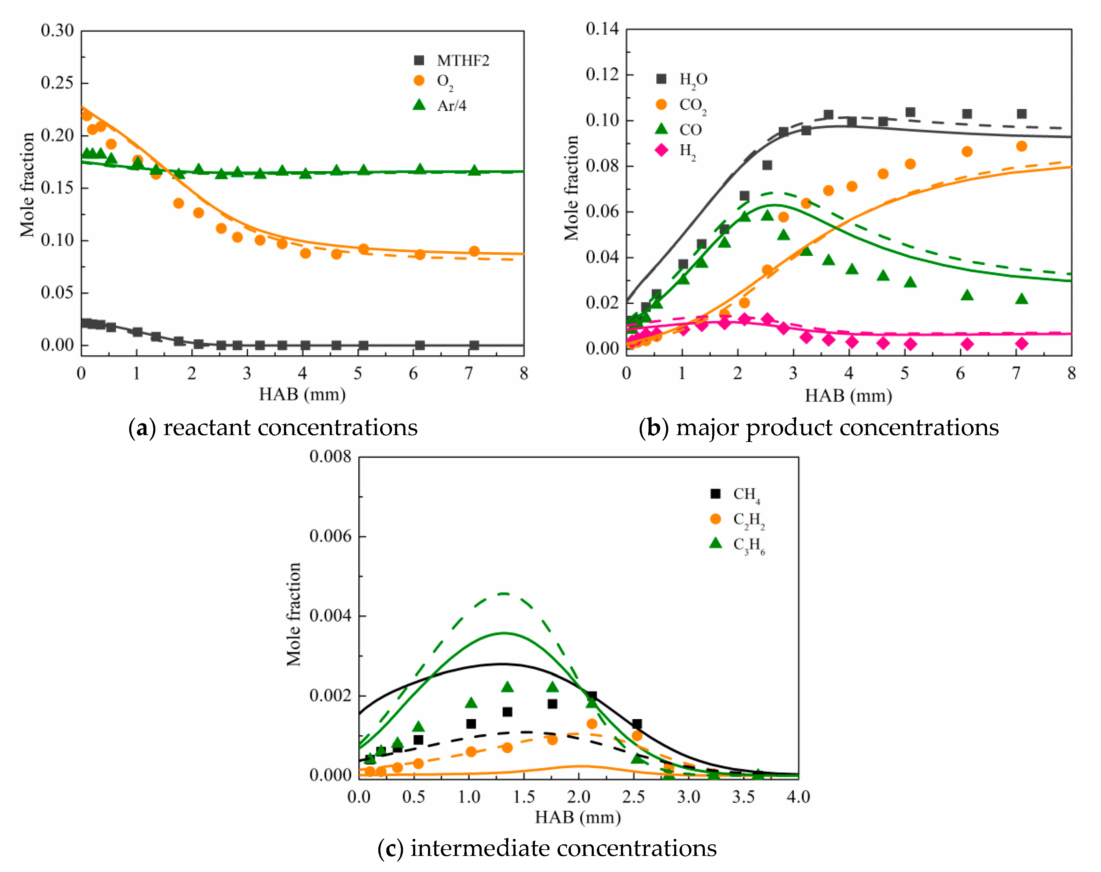
3.2. Validation against Species Concentration Profiles

Figure 9 demonstrates the measurements [36] and predictions for the major JSR species profiles of synthetic diesel fuel, including O2, carbon monoxide (CO), carbon dioxide (CO2), hydrogen (H2), methane (CH4), formaldehyde (CH2O), acetylene (C2H2). The experimental results were determined by Mati and his co-workers [36] over the temperature range of 800–1200 K, φ = 0.5 and 2.0, at 10 atm with residence time (τ) of 0.5 s. As seen, the proposed mechanism tends to slightly under-estimate the reactivity in the two operating conditions. The predicted CO and H2 concentrations agree with those of the measurements very well. Although some deviations between the predicted values and the measurements were noticed for the CO2, CH4 and CH2O profiles, the varying tendencies for the three species can be well captured under the operating conditions. C2H2 has been considered an important soot precursor [4,26]. As presented in Figure 9a, the simulated C2H2 concentration at lean condition (φ = 0.5) meets the experimental data quite well. However, the experimental C2H2 mole fraction profile was not fully captured with the developed mechanism under fuel-rich conditions (φ = 2.0), although the maximum mole fraction of C2H2 was properly predicted, as displayed in Figure 9b. Overall, the proposed mechanism performs satisfactorily against the experimental species concentration profiles considering its small size and the difference in component composition between the surrogate model and synthetic diesel.
Bruycker et al. [16] measured the species mole fraction profiles in premixed MTHF2/O2/Ar flames at 6.7 kPa and φ = 0.7, 1.0 and 1.3. In Figure 10, Figure 11 and Figure 12, the measurements of reactants, major combustion products and three selected intermediate species in the three premixed flames are compared to the simulated results with the reduced diesel/MTHF2 mechanism and the detailed MTHF2 mechanism [17]. As shown, the mole fractions of reactants and major products were reasonably reproduced using the two models. However, the simulations for the concentrations of CH4, C2H2 and propylene (C3H6) with the reduced diesel/MTHF2 mechanism were only in qualitative agreement with those experimental values, especially the detailed mechanism performs well for the C2H2 profile. Regardless, the proposed mechanism qualitatively predicted the shape of C2H2 profiles with 81.86%, 78.84% and 73.93% under-prediction of the peak value of C2H2 concentration at φ = 0.7, 1.0 and 1.3, respectively, this behavior can be mainly ascribed to the simplification of the MTHF2 sub-mechanism.

3.3. Validation against Laminar Flame Speeds

Figure 13 compares the experimental [37,38] and predicted LFSs for ultra-low sulphur grade diesel under atmospheric pressure at an elevated temperature of 470 K. Basically, predicted results with the developed mechanism reasonably match those of the experimental flame velocities and the maximum error was 14.67%. As known, the reactions containing small radicals and hydrocarbons dominate the flame velocities [22], and these reactions in the base diesel surrogate mechanism are kept unmodified, which have been widely verified by comparing fundamental experimental results. The agreement between the measurements and simulations can be acceptable by considering the difference in components between the surrogate model and real diesel, and the uncertainties in the measurements.
Figure 14 displays the predicted LFSs of MTHF2/air mixtures using the proposed mechanism compared with the measured results taken from Wang et al. [20]. The predicted values using the detailed MTHF2 mechanism [17] are also included. As can be seen, the maximum flame velocity appears around φ = 1.1 for a given initial temperature and pressure, and the LFSs of MTHF2/air mixtures were observed to decrease with the initial temperature decrease or pressure increase. Generally speaking, a good match between predicted values with the proposed mechanism and measurements was achieved, and the current mechanism can well capture the dependence of flame velocities on temperature and pressure.

3.4. Validation against the Dual Fuel Combustion in the Engine

A single-cylinder dual-fuel engine was employed for conducting new dual-fuel engine experiments. Figure 15 displays the dual-fuel engine test system. Table 2 presents the engine specifications and operating conditions. During the experiments, commercial China-VI diesel was directly injected into the combustion chamber with a pressure of 60 MPa. A low-pressure injector mounted in the intake port was used to supply MTHF2 fuel to the intake manifold to form the homogeneous charge, and the start of injection (SOI) timing was kept at −300 degrees crank angle (°CA) after top dead center (ATDC). Two cases with different diesel injection timing were used, with a diesel-equivalent total energy of about 18.2 mg/cyc. Pure diesel (M00) and M30 (the energy percentage of MTHF2 is 30%) fuels were prepared and tested.
A dual-fuel engine modelling study was performed with the KIVA-3V code [30], and the simulated values were compared with measured results to appraise the predictive capacity of the current mechanism on ICE. Table 3 summarizes the physicochemical models used in this study. In addition, diesel spray and combustion processes were simulated with the single-physical multi-chemical model [39,40]. The non-chemical-kinetic process of diesel was simulated with the diesel fuel model DF2, and the ignition and combustion processes of fuel/air mixture were modeled using the developed diesel/MTHF2 model, and a mixture of 26.67% n-decane/14.89% iso-octane/36.81% MCH/21.64% toluene was used as diesel surrogate. To reduce the computational cost, a 40-degree (1/9 of the cylinder) mesh with the flat-top piston geometry was adopted, as illustrated in Figure 16.
Figure 17 depicts the comparisons of the experimental data of in-cylinder pressure and HRR and the simulations for M00 and M30 combustion under two different diesel injection timings. As can be seen, the experiments of in-cylinder pressure and HRR can be well reproduced using the proposed mechanism, although slightly higher HRR profiles were predicted. The predicted difference may be due to the uncertainties of measurements and simulation settings. Overall, the developed mechanism can reasonably simulate the combustion behavior of diesel/MTHF2 dual-fuel engines.

4. Conclusions

In this study, a reduced diesel/MTHF2 mechanism containing 78 species and 233 reactions was developed. A diesel surrogate model consisting of n-decane, iso-octane, MCH and toluene was selected as the base mechanism. Then, a reduced MTHF2 mechanism involving 54 species and 294 reactions was obtained based on the methods of DRGEP, RPA and isomer lumping. After that, a combined five-component mechanism was formulated by coupling the base diesel surrogate mechanism and the reduced MTHF2 mechanism based on the decoupling methodology. Finally, the rate parameters of some reactions in the MTHF2 sub-mechanism were adjusted to improve the reproducibility. The proposed diesel/MTHF2 mechanism was validated by comparing the literature data and the new experimental data in terms of ignition delays, flame species concentrations, LFSs, in-cylinder pressure and HRR traces of dual-fuel engine combustion. The validation results illustrate that the proposed reduced mechanism can give a fairly good prediction on the measurements, but there is room for improvement in terms of predicting the IDTs of MTHF2 at high temperatures and the small species concentrations in JSRs and premixed laminar flames. Overall, the proposed mechanism could be applied for modelling diesel/MTHF2 dual-fuel engine combustion.

Author Contributions

Conceptualization, S.L. and J.L.; methodology, S.L. and J.L.; software, C.H.; validation, S.L. and C.H.; formal analysis, C.Y. and W.Y.; investigation, S.L.; resources, S.L.; data curation, S.L.; writing—original draft preparation, S.L.; writing—review and editing, C.H. and T.Z.; visualization, S.L.; supervision, J.L.; project administration, J.L. and T.Z.; funding acquisition, S.L. All authors have read and agreed to the published version of the manuscript.

Funding

This research was funded by the Science and Technology Development Project of Anyang city, grant number 2021C01GX006; Doctoral Start-up Funding of Anyang Institute of Technology, grant number BSJ2019006; Key Scientific Research Projects of Colleges and Universities in Henan Province, grant number 21B470002.

Data Availability Statement

Not applicable.

Conflicts of Interest

The authors declare no conflict of interest.

References

  1. Daniel, R.; Wei, L.X.; Xu, H.M.; Wang, C.M.; Wyszynski, M.L.; Shuai, S.J. Speciation of hydrocarbon and carbonyl emissions of 2,5-dimethylfuran combustion in a DISI engine. Energy Fuels 2012, 26, 6661–6668. [Google Scholar] [CrossRef]
  2. Wu, Y.; Zhang, X.; Zhang, Z.; Wang, X.; Geng, Z.; Jin, C.; Liu, H.F.; Yao, M.F. Effects of diesel-ethanol-THF blend fuel on the performance and exhaust emissions on a heavy-duty diesel engine. Fuel 2020, 271, 117633. [Google Scholar] [CrossRef]
  3. Xiao, H.L.; Yang, X.L.; Hou, B.B.; Wang, R.; Xue, Q.; Ju, H.L. Combustion performance and pollutant emissions analysis of a diesel engine fueled with biodiesel and its blend with 2-methylfuran. Fuel 2019, 237, 1050–1056. [Google Scholar] [CrossRef]
  4. Liu, X.; Wang, H.; Wei, L.; Liu, J.; Reitz, R.D.; Yao, M. Development of a reduced toluene reference fuel (TRF)-2,5-dimethylfuran-polycyclic aromatic hydrocarbon (PAH) mechanism for engine applications. Combust. Flame 2016, 165, 453–465. [Google Scholar] [CrossRef]
  5. Li, S.; Huang, C.; Liu, J.P.; Zhang, T.T. Development of a reduced n-heptane/toluene/tetrahydrofuran mechanism for dual-fuel engine combustion prediction. Fuel 2022, 326, 124914. [Google Scholar] [CrossRef]
  6. Grochowski, M.R.; Yang, W.; Sen, A. Mechanistic study of a one-step catalytic conversion of fructose to 2,5-dimethyltetrahydrofuran. Chem. A Eur. J. 2012, 18, 12363–12371. [Google Scholar] [CrossRef] [PubMed]
  7. Yang, W.; Sen, A. One-step catalytic transformation of carbohydrates and cellulosic biomass to 2,5-dimethyltetrahydrofuran for liquid fuels. ChemSusChem 2010, 3, 597–603. [Google Scholar] [CrossRef]
  8. Li, Y.; Xu, W.; Jiang, Y.; Liew, K.M.; Qiu, R. Laminar burning velocities of 2-methyltetrahydrofuran at elevated pressures. Proc. Combust. Inst. 2021, 38, 2175–2183. [Google Scholar] [CrossRef]
  9. Rudolph, T.W.; Thomas, J.J. NOx, NMHC and CO emissions from biomass derived gasoline extenders. Biomass 1988, 16, 33–49. [Google Scholar] [CrossRef]
  10. Lucas, S.V.; Loehr, D.A.; Meyer, M.E.; Thomas, J.J.; Gordon, E.E. Exhaust emissions and field trial results of a new, oxygenated, non-petroleum-based, waste-derived gasoline blending component: 2-methyltetrahydrofuran. In Proceedings of the Fuels and Lubricants Meeting and Exposition, Philadelphia, PA, USA, 18–21 October 1993. [Google Scholar]
  11. Thewes, M.; Muther, M.; Brassat, A.; Pischinger, S.; Sehr, A. Analysis of the effect of biofuels on the combustion in a fownsized DI SI Engine. SAE Int. J. Fuels Lubr. 2011, 5, 274–288. [Google Scholar] [CrossRef]
  12. Janssen, A.J.; Kremer, F.W.; Baron, J.H.; Muether, M.; Pischinger, S.; Klankermayer, J. Tailor-Made fuels from biomass for homogeneous low-temperature diesel combustion. Energy Fuels 2011, 25, 4734–4744. [Google Scholar] [CrossRef]
  13. Hülser, T.; Grünefeld, G.; Brands, T.; Günther, M.; Pischinger, S. Optical investigation on the origin of pre ignition in a highly boosted SI engine using bio-fuels. In Proceedings of the SAE 2013 World Congress & Exhibition, Detroit, MI, USA, 16–18 April 2013. [Google Scholar]
  14. Moshammer, K.; Vranckx, S.; Chakravarty, H.K.; Parab, P.; Fernandes, R.X.; Kohse-Höinghaus, K. An experimental and kinetic modeling study of 2-methyltetrahydrofuran flames. Combust. Flame 2013, 160, 2729–2743. [Google Scholar] [CrossRef]
  15. Wang, J.; Wang, X.; Fan, X.; Yang, K. Shock tube experimental and modeling study of MTHF ignition characteristics at high temperatures. In Proceedings of the JSAE/SAE 2015 International Powertrains, Fuels & Lubricants Meeting, Kyoto, Japan, 1–4 September 2015. [Google Scholar]
  16. De Bruycker, R.; Tran, L.S.; Carstensen, H.H.; Glaude, P.A.; Monge, F.; Alzueta, M.U.; Battin-Leclerc, F.; van Geem, K.M. Experimental and modeling study of the pyrolysis and combustion of 2-methyltetrahydrofuran. Combust. Flame 2017, 176, 409–428. [Google Scholar] [CrossRef] [Green Version]
  17. Tripathi, R.; Lee, C.; Fernandes, R.X.; Olivier, H.; Curran, H.J.; Sarathy, S.M.; Pitsch, H. Ignition characteristics of 2-methyltetrahydrofuran: An experimantal and kinetic study. Proc. Combust. Inst. 2017, 36, 587–595. [Google Scholar] [CrossRef] [Green Version]
  18. Fenard, Y.; Boumehdi, M.A.; Vanhove, G. Experimental and kinetic modeling study of 2-methyltetrahydrofuran oxidation under engine-relevant conditions. Combust. Flame 2017, 178, 168–181. [Google Scholar] [CrossRef]
  19. Wang, J.; Wang, X.; Fan, X.; Yang, K.; Zhang, Y. An ignition delay time and kinetic study of 2-methyltetrahydrofuran at high temperatures. Fuel 2016, 186, 758–769. [Google Scholar] [CrossRef]
  20. Wang, X.; Fan, X.; Yang, K.; Wang, J.; Jiao, X.; Guo, Z. Laminar flame characteristics and chemical kinetics of 2-methyltetrahydrofuran and the effect of blending with iso-octane. Combust. Flame 2018, 191, 213–225. [Google Scholar] [CrossRef]
  21. Wu, S.H.; Tay, K.L.; Yu, W.B.; Lin, Q.J.; Li, H.; Zhao, F.Y.; Yang, W.M. Development of a highly compact and robust chemical reaction mechanism for the oxidation of tetrahydrofurans under engine relevant conditions. Fuel 2020, 276, 118034. [Google Scholar] [CrossRef]
  22. Chang, Y.; Jia, M.; Li, Y.; Liu, Y.; Xie, M.; Wang, H.; Reltz, R.D. Development of a skeletal mechanism for diesel surrogate fuel by using a decoupling methodology. Combust. Flame 2015, 162, 3785–3802. [Google Scholar] [CrossRef]
  23. Liu, Y.D.; Jia, M.; Xie, M.Z.; Pang, B. Improvement on a skeletal chemical kinetic model of iso-octane for internal combustion engine by using a practical methodology. Fuel 2013, 103, 884–891. [Google Scholar] [CrossRef]
  24. Pitz, W.J.; Mueller, C.J. Recent progress in the development of diesel surrogate fuels. Prog. Energy Combust. Sci. 2011, 37, 330–350. [Google Scholar] [CrossRef] [Green Version]
  25. Pepiot-Desjardins, P.; Pisch, H. An efficient error-propagation-based reduction method for large chemical kinetic mechanisms. Combust. Flame 2008, 154, 67–81. [Google Scholar] [CrossRef]
  26. Li, S.; Li, Y.; Liu, J.P.; Meng, W.; Wang, M.Y.; Cao, Y.S.; Cao, S.; Yao, L.B.; Zhang, K.P. Development of a phenomenological soot model integrated with a reduced TRF-PAH mechanism for diesel engine application. Fuel 2021, 283, 118810. [Google Scholar] [CrossRef]
  27. Liu, X.L.; Wang, H.; Zheng, Z.Q.; Liu, J.L.; Reitz, R.D.; Yao, M.F. Development of a combined reduced primary reference fuel-alcohols (methanol/ethanol/propanols/butanols/n-pentanol) mechanism for engine applications. Energy 2016, 114, 542–558. [Google Scholar] [CrossRef]
  28. Wang, H.; Yao, M.F.; Yue, Z.Y.; Jia, M.; Reitz, R.D. A reduced toluene reference fuel chemical kinetic mechanism for combustion and polycyclic-aromatic hydrocarbon predictions. Combust. Flame 2015, 162, 2390–2404. [Google Scholar] [CrossRef]
  29. Kee, R.J.; Rupley, F.M.; Miller, J.A. CHEMKIN II: A Fortran Chemical Kinetics Package for the Analysis of Gas-Phase Chemical Kinetics; Technical Report; Sandia National Laboratories: Livermore, CA, USA, September 1989. [Google Scholar]
  30. Amsden, A.A. Kiva-3v: A Block-Structured Kiva Program for Engines with Vertical or Canted Valves; Technical Report; Los Alamos National Lab: Los Alamos, NM, USA, July 1997. [Google Scholar]
  31. Gowdagiri, S.; Wang, W.; Oehlschlaeger, M.A. A shock tube ignition delay study of conventional diesel fuel and hydroprocessed renewable diesel fuel from algal oil. Fuel 2014, 128, 21–29. [Google Scholar] [CrossRef]
  32. Kukkadapu, G.; Sung, C.J. Autoignition study of ULSD#2 and FD9A diesel blends. Combust. Flame 2016, 166, 45–54. [Google Scholar]
  33. Wang, S.X.; Mao, Y.B.; Raza, M.; Yu, L.; Lu, X.C. Autoignition of diesel/oxygen/nitrogen mixture under elevated temperature in a heated shock tube. Fuel 2019, 254, 115635. [Google Scholar] [CrossRef]
  34. Yu, L.; Mao, Y.B.; Qiu, Y.; Wang, S.X.; Li, H.; Tao, W.C.; Qian, Y.; Lu, X.C. Experimental and modeling study of the autoignition characteristics of commercial diesel under engine-relevant conditions. Proc. Combust. Inst. 2019, 37, 4805–4812. [Google Scholar] [CrossRef]
  35. Villano, S.M.; Huynh, L.K.; Carstensen, H.H.; Dean, A.M. High-pressure rate rules for Alkyl+O2 reactions. 1. the dissociation, concerted elimination, and isomerization channels of the alkyl peroxy radical. J. Phys. Chem. A 2015, 115, 13425–13442. [Google Scholar] [CrossRef]
  36. Mati, K.; Ristori, A.; Gaiel, S.; Pengloan, G.; Dagaut, P. The oxidation of a diesel fuel at 1–10 atm: Experimental study in a JSR and detailed chemical kinetic modeling. Proc. Combust. Inst. 2007, 31, 2939–2946. [Google Scholar] [CrossRef]
  37. Bai, Y.Q.; Wang, Y.; Wang, X.C.; Wang, P. Development of a skeletal mechanism for tri-component diesel surrogate fuel: N-hexadecane/iso-cetane/1-methylnaphthalene. Fuel 2020, 259, 116217. [Google Scholar] [CrossRef]
  38. Chong, C.T.; Hochgreb, S. Measurements of laminar flame speeds of liquid fuels: JetA1, diesel, palm methyl esters and blends using particle imaging velocimetry (PIV). Proc. Combust. Inst. 2011, 33, 979–986. [Google Scholar] [CrossRef]
  39. Chang, Y.; Jia, M.; Li, Y.; Zhang, Y.; Xie, M.; Wang, H.; Reitz, R.D. Development of a skeletal oxidation mechanism for biodiesel surrogate. Proc. Combust. Inst. 2015, 35, 3037–3044. [Google Scholar] [CrossRef]
  40. Wang, P.; Jia, M.; Zhang, Y.; Xu, G.; Chang, Y.; Xu, Z. Development of a decoupling physical-chemical surrogate (DPCS) model for simulation of the spray and combustion of multi-component biodiesel fuels. Fuel 2019, 240, 16–30. [Google Scholar] [CrossRef]
  41. Han, Z.; Reitz, R.D. Turbulence modeling of internal combustion engines using RNG k-ε; models. Combust. Sci. Technol. 1995, 106, 267–295. [Google Scholar] [CrossRef]
  42. Han, Z.; Reitz, R.D. A temperature wall function formulation for variable-density turbulent flows with application to engine convective heat transfer modeling. Int. J. Heat Mass Transf. 1997, 40, 613–625. [Google Scholar] [CrossRef]
  43. Ricart, L.M.; Reltz, R.D.; Dec, J.E. Comparisons of diesel spray liquid penetration and vapor fuel distributions with in-cylinder optical measurements. J. Eng. Gas Turbines Power 2000, 122, 588–595. [Google Scholar] [CrossRef]
  44. Nordin, N. Complex Chemistry Modeling of Diesel Spray Combustion. Ph.D. Thesis, Chalmers University of Technology, Goteborg, Sweden, 2001. [Google Scholar]
  45. Han, Z.Y.; Xu, Z.; Trigui, N. Spray/wall interaction models for multidimensional engine simulation. Int. J. Engine Res. 2000, 1, 127–146. [Google Scholar] [CrossRef]
Figure 1. Predicted ignition delays of MTHF2 by detailed mechanism [17] (symbols) and reduced mechanism (lines) based on DRGEP + RPA.
Energies 15 07677 g001
Figure 2. Schematic of RPA for stoichiometric MTHF2/air at 20% fuel consumption at a pressure of 40 bar, temperatures of 700 K (black numbers) and 1500 K (red numbers).
Energies 15 07677 g002
Figure 3. Predicted ignition delays of MTHF2 by detailed mechanism [17] (symbols) and reduced mechanism (lines) based on DRGEP + RPA+ isomers lumping.
Energies 15 07677 g003
Figure 4. Sensitivity coefficients of ignition delays for reactions involved in the MTHF2 sub-mechanism.
Energies 15 07677 g004
Figure 5. Ignition delay comparisons between simulation and experiment [31,32,33,34] for diesel fuel at φ = 0.5. Symbols: experiment; lines: simulation.
Energies 15 07677 g005
Figure 6. Ignition delay comparisons between simulation and experiment [31,32,33,34] for diesel fuel at φ = 1.0. Symbols: experiment; lines: simulation.
Energies 15 07677 g006aEnergies 15 07677 g006b
Figure 7. Measured (symbols) [17] and calculated (lines) ignition delay times for MTHF2. Solid lines: reduced diesel/MTHF2 mechanism; dashed lines: detailed MTHF2 mechanism [17].
Energies 15 07677 g007aEnergies 15 07677 g007b
Figure 8. Measured (symbols) [19] and calculated (lines) ignition delay times for MTHF2. Solid lines: reduced diesel/MTHF2 mechanism; dashed lines: detailed MTHF2 mechanism [17].
Energies 15 07677 g008
Figure 9. Measured (symbols) [36] and calculated (lines) species concentrations in a JSR for synthetic diesel fuel/air mixtures at 10 atm, τ = 0.5 s, φ = 0.5 and 2.0.
Energies 15 07677 g009
Figure 10. Measured (symbols) [16] and calculated (lines) species concentrations in premixed MTHF2 flames at φ = 0.7. Solid lines: reduced diesel/MTHF2 mechanism; dashed lines: detailed MTHF2 mechanism [17].
Energies 15 07677 g010
Figure 11. Measured (symbols) [16] and calculated (lines) species concentrations in premixed MTHF2 flames at φ = 1.0. Solid lines: reduced diesel/MTHF2 mechanism; dashed lines: detailed MTHF2 mechanism [17].
Energies 15 07677 g011aEnergies 15 07677 g011b
Figure 12. Measured (symbols) [16] and calculated (lines) species concentrations in premixed MTHF2 flames at φ = 1.3. Solid lines: reduced diesel/MTHF2 mechanism; dashed lines: detailed MTHF2 mechanism [17].
Energies 15 07677 g012
Figure 13. Measured (symbols) [37,38] and calculated (lines) laminar flame speeds of diesel/air mixtures.
Energies 15 07677 g013
Figure 14. Measured (symbols) [36] and calculated (lines) species concentrations in a JSR for synthetic diesel fuel/air mixtures at 10 atm, τ = 0.5 s, φ = 0.5 and 2.0.
Energies 15 07677 g014
Figure 15. Schematic of the experimental setup.
Energies 15 07677 g015
Figure 16. Computational mesh.
Energies 15 07677 g016
Figure 17. Comparisons between the modeled and experimental in-cylinder pressure and HRR profiles for M00 and M30.
Energies 15 07677 g017
Table 1. Reactions in MTHF2 sub-mechanism.
ReactionsA (cm, mol, s)βE (cal/mol)Ref.
R1MTHF2 + OH = MTHF25J + H2O2.400 × 1062.00−2630[17]
R2MTHF2 + H = MTHF25J + H25.800 × 1042.492330This work
R3MTHF2 + HO2 = MTHF25J + H2O22.800 × 1052.6915,348This work
R4MTHF2 + O2 = MTHF25J + HO22.865 × 10130.0047,640[17]
R5MTHF25J + O2 = MTHF25OOJ6.046 × 1014−0.92−130[17]
R6MTHF25OOJ = MTHF25OOH2J3.080 × 1061.5314,622[17]
R7MTHF25OOH2J + O2 = MTHF25OOH2O22.464 × 10100.40−800[17]
R8MTHF25OOH2O2 = MTHF22OOH5KET + OH3.616 × 10100.1314,470[17]
R9MTHF22OOH5KET => CH3CO + C2H4 + CO2 + OH4.494 × 10130.0041,600This work
R10MTHF25OOH2J => MTHF2O2-5 + OH6.520 × 1090.109330[17]
R11MTHF2O2-5 + OH => H2O + CH3 + 2CH2CO6.064 × 1090.000This work
R12MTHF25J = O*CCCCJC5.000 × 10120.0021,821This work
R13O*CCCCJC = C3H6 + CH2CHO5.000 × 10130.0019,789[17]
Table 2. Dual-fuel engine specifications and operating conditions.
ParameterValue
Number of valves4
Bore × Stroke (mm × mm)96 × 115
Piston typeflat
Engine speed (rpm)1000
Intake temperature (K)338
Intake pressure (bar)1.04
Diesel fuel injectorBosch, 9 holes, 60MPa fuel injection pressure
Diesel injection timing (CA ATDC)−12.5°, −10°
Port fuel injectorDelphi, 6 holes, 0.5MPa fuel injection pressure
Port fuel injection timing (CA ATDC)−300°
EGR ratio (%)0
Table 3. Computational sub-models used in the engine simulations.
PhenomenonModel
TurbulenceRenormalized (RNG) k-ε model [41]
Heat transferHan and Reitz model [42]
Spray breakupKH-RT model [43]
Collision modelNordin model [44]
Spray-wall interaction modelHan model [45]
Combustion modelCHEMKIN [29]
Publisher’s Note: MDPI stays neutral with regard to jurisdictional claims in published maps and institutional affiliations.

