Article

Double Cathode Modification Improves Charge Transport and Stability of Organic Solar Cells

Department of Physics, Beijing Technology and Business University, Beijing 100048, China
*
Author to whom correspondence should be addressed.
Energies 2022, 15(20), 7643; https://doi.org/10.3390/en15207643
Submission received: 4 October 2022 / Revised: 11 October 2022 / Accepted: 13 October 2022 / Published: 16 October 2022
(This article belongs to the Special Issue High-Efficiency Organic Photovoltaics)

Abstract

:
Introducing a cathode modification layer is an effective method to obtaining highly efficient organic solar cells (OSCs) and improving their stability. Herein, we innovatively introduced a double cathode modification layer (SnO2/ZnO) into a non-fullerene OSCs based on PM7:IT-4F and explored the mechanisms. The effects of SnO2/ZnO film on charge carriers transfer in OSCs are studied via a variety of electrical testing methods including Photo-CELIV measurements. As a result, a cathode buffer layer with low recombination rate and high carrier mobility could be introduced, which is beneficial to electron transport and collection. The champion device based on the double cathode modification layer acquires an efficiency of 12.91%, obviously higher than that of the single cathode modification layer (SnO2 or ZnO) device. Moreover, The SnO2/ZnO double layer is demonstrated to be of great help in the improvement of device stability, and our work could provide a new inspiration for the preparation of OSCs cathode modification layer.

1. Introduction

Over recent years, remarkable progress have been made in the field of organic solar cells (OSCs), which is considered a potential candidate to accessing clean energy [1,2,3]. Most of these breakthroughs are owing to synthetic new materials [4,5,6,7], optimization of device structure [8,9,10], morphology control of active layers [11,12,13], as well as adopting the interface modification layers which have been considered an efficient method to achieve high-efficient and stable OSCs for the advantages of adjusting the energy barrier between electrode and organic active layers and improving the charge extraction ability of the electrode [14,15,16]. Poly(3,4-(ethylenedioxy)thiophene):poly(styrenesulfonate) (PEDOT:PSS) is the most commonly used anode buffer layer materials in the normal OSCs fabrication for their superior hole transport capability, good transparency in the spectral response range and so on [17,18]. While for cathode buffer layer, the most commonly used modification materials can be divided into two categories: inorganic materials and organic materials. Inorganic materials are mainly metal oxides, such as zinc oxide (ZnO) [19,20], titanium oxide (TiOX) [21], lithium fluoride (LiF) [22]. For organic materials, poly[(9,9-bis(3′-(N,N-dimethylamino)propyl)-2,7-fluorene)-alt-2,7-(9,9 –dioctylfluorene)] (PFN) [23,24,25], Polyethylenimine ethoxylated (PEIE) [26], perylene diimide derivatives (PDIN-o) [27,28] and PDIN [29,30] are usually used.
Except the power conversion efficiency (PCE), the long-term stability still remains to be a great challenge of OSCs development which is always overlooked by high-efficiency device reports. At present, the main way to enhance the lifetime of OSCs is to consider how to slow down the rate of erosion caused by moisture and oxygen. Methods have been taken, such as synthesizing hydrophobic organic materials, encapsulating devices, and so on [31,32,33]. Moreover, regulation of electrode modification layer has been considered an important approach to resist moisture and oxygen molecules into device [34,35], which can affect both active layer and electrode for the special location in the device structure. Therefore, the study of electrode modification layer is of great significance for enhancing device efficiency and stability simultaneously.
In this work, we fabricated the inverted OSCs based on Poly[(2,6-(4,8-bis(5-(2-ethylhexyl-3-chloro)thiophen-2-yl)-benzo[1,2-b:4,5-b’]dithiophene))-alt-(5,5-(1′,3′-di-2-thienyl-5′,7′-bis(2-ethylhexyl)benzo[1′,2′-c:4′,5′-c’]dithiophene-4,8-dione)] (PM7) as donor and 3,9-bis(2-methylene-((3-(1,1-dicyanomethylene)-6,7-difluoro)-indanone))-5,5,11,11-tetrakis(4-hexylphenyl)-dithieno[2,3-d:2′,3′-d’]-s-indaceno[1,2-b:5,6-b’]dithiophene (IT-4F) as acceptor with SnO2/ZnO (ZnO and SnO2 for comparison) as cathode modification layer. It should be noted that the use of a double layer of inorganic material as a charge transport layer (electrode modification layer) has been previously used in devices based on other material systems (such as perovskite) [36,37,38], but to our knowledge has not been used in PM7:IT-4F based OSCs. SnO2/ZnO film improves the power conversion efficiency (PCE) of the device to 12.91% with FF of 70%, JSC of 20.04 mA/cm2 and VOC of 0.92 V, due to the improvement of charge transfer/collection. Moreover, compared with the single cathode modification layer (ZnO, SnO2), the adoption of SnO2/ZnO film effectively improves the stability of the device, with a reduced rate of dark-degradation in both air and nitrogen. Taken together, this work would provide insights into OSCs interfacial modification mechanism study with new revelation in-depth elucidation of the underlying mechanisms associated with improved device efficiency and stability, which will provide insights into OSCs interfacial modification studies.

2. Materials and Methods

The active polymer PM7 and Non-fullerene small molecule material IT-4F were used as donor and acceptor, respectively. Active layer solvent is o-Xylene (OX). ZnO, SnO2 and MoO3 were utilized in the preparation of electron-transport layer and anode buffer layer, respectively. Among them, ZnO was prepared by sol gel with Zn(Ac)2·2H2O, C2H7NO and C3H8O2. PM7 and small molecule acceptor material IT-4F were purchased from 1-Material Inc (Dorval, Quebec, Canada). Organic reagents such as OX, DClO, C2H7NO, C3H8O2 and CH2Cl2 were acquired from Sigma-Aldrich (Merck KGaA, Darmstadt, Germany). Zn(Ac)2·2H2O and SnO2 were purchased from J&K Scientific (Beijing, China). All the materials were used as received without any further treatment. Donor material PM7 and acceptor material IT-4F were put into a solution bottle (Agilent, Santa Clara, California, United States) in a mass ratio of 1.25:1, and added CH2Cl2 (1.5 μL/mg). Then left the bottle in glove box (Mikrouna, Shanghai, China) with high purity nitrogen to dry thoroughly and await further processing. Once the organic materials (PM7 and IT-4F) dried, donor and acceptor materials were dissolved in OX (20 mg/mL) by heating 60 °C with stirring for 6 h. As for ZnO precursor solution, in briefly, 164.61 mg of Zn(Ac)2·2H2O and 45.81 mg of C2H7NO (molar ratio 1:1) were dissolved in 1 mL C3H8O2 and then stirred continuously in the dark, heating 60 °C, until the solids completely dissolved (almost 12 h). SnO2 solution (purchased from J&K Scientific, Beijing, China) was diluted by adding deionized water in a volume ratio of 1:6 for further use.
Devices were fabricated by featuring three kinds of cathode modification layer (ZnO, SnO2 and SnO2/ZnO), respectively, in an inverted structure: indium tin oxide (ITO)/buffer layer/PM7:IT-4F/MoO3/Ag (Figure 1a). The chemical structural formulas of the donor material PM7 and the acceptor material IT-4F used in the experiment are shown in Figure 1b, c. For the device preparation, all the devices were fabricated on cleaned ITO-coated glass substrates (sheet resistance: 15 Ω/Sq), cleaned by followed steps with sequential sonication in deionized water, acetone, ethanol each for 20 min. Wait until the ITO-coated substrate fully dries by high purity nitrogen for further ultraviolet-ozone treatment for 8 min. The buffer layer was spin coated on the treated ITO substrates as cathode modification layer using a sol-gel process. Next, it was thermal-annealed at 150 °C for 30 min (for ZnO), 200 °C for 60 min (for SnO2) and 180 °C for 40 min (for SnO2/ZnO). Subsequently, place the prepared ITO/cathode modification layer films into the glove box filled with high purity nitrogen (O2 and H2O content < 0.01 ppm), and then a blend layer of PM7:IT-4F was spin-coated on the films and dried for 30 min to obtain the dry active layer film. Place the ITO/cathode modification layer/active layer in a thermal evaporative coating instrument (Mikrouna, Shanghai, China), vacuumed to a vacuum of 1.5 × 10⁻⁶ Torr, and then MoO3 and silver were successively deposited as anode buffer layer and anode, respectively.
The thickness for each layer of the device (including anode modification layer, cathode modification layer, active layer and Ag electrode) was measured via the Dektak XT Stylus Profile (Bruker Corporation, Billerica, MA, USA). The UV-vis absorption spectra of PM7:IT-4F films (with different electronic transport layer, including ZnO, SnO2 and SnO2/ZnO) were recorded using a U3900H spectrophotometer (Hitachi, Tokyo, Japan). The Keithley 2400 measurement unit (Tektronix Inc., Beaverton, OR, United States) was used to obtain the current density-voltage (J-V) characteristic curves (AM 1.5G) of each device (San-Ei Electric, Osaka, Japan). The EQE curves of each device was measured by a SC100 solar cell QE/IPCE testing system (Zolix Instruments CO., Ltd., Beijing, China). In addition, The Paios carrier characterization system (FLUXiM AG, Winterthur, Switzerland) was utilized to measure the TPV/TPC and Photo-CELIV.

3. Results and Discussion

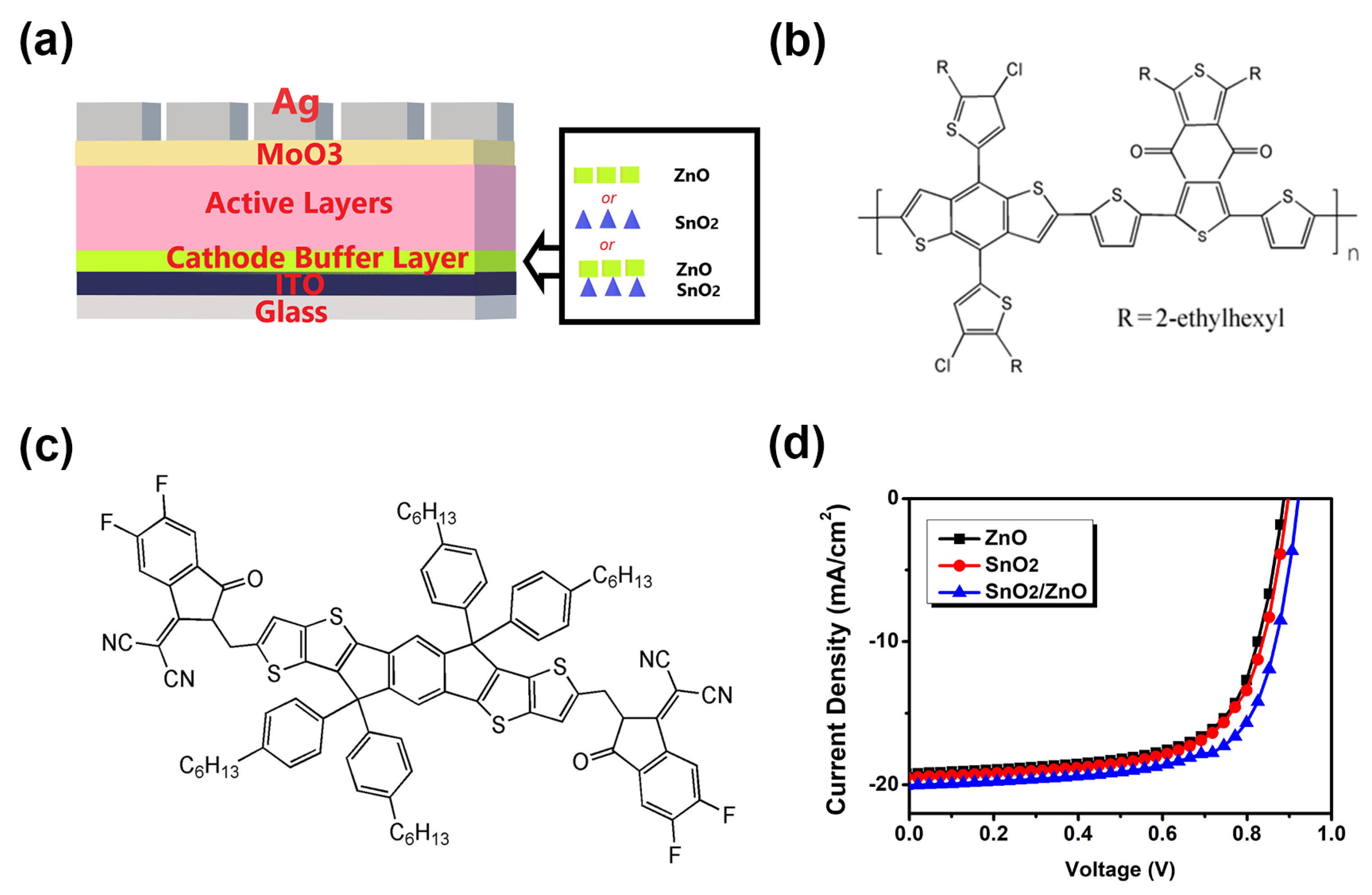
3.1. Device Performance

As shown in, organic solar cells were fabricated with different electron transport layer (ZnO, SnO2 and SnO2/ZnO). The J-V curves of the devices are shown in Figure 1d, while the relevant photovoltaic parameters are listed in Table 1, including short-circuit current density (JSC), open-circuit voltage (VOC), fill factor (FF) and power conversion efficiency (PCE). Meanwhile, the parameters of OSCs based on PM7:IT-4F active layer in other studies are presented in Table 2 for reference. By modified with SnO2/ZnO, the device exhibits a PCE of 12.9% with a JSC of 20.04 mA/cm2, a VOC of 0.91 V and a FF of 70%. For comparation, the device with single cathode buffer layer ZnO shows a PCE of 11.45%, and JSC, VOC and FF are 19.22 mA/cm2, 0.88 V and 67%, respectively. While the SnO2 modified device shows a PCE of 12.03%, a JSC of 19.45 mA/cm2, a VOC of 0.90 V and a FF of 68%.
Compared to the device with the ZnO buffer layer the SnO2 cathode modifier layer device shows a significant improvement of FF and JSC, which is due to the fact that SnO2 film is smoother than ZnO film (see Figure S1) and would form better contact with the active layer. While the device base on SnO2/ZnO modification layer gives the best performance for all parameters, we think there are two main reasons for this. On one hand, it has been shown that preparing SnO2 on ITO can improve the surface of ITO [46], and we speculate that inserting a layer of SnO2 between ITO and ZnO could improve the quality of ZnO film, which is more conducive to the transmission of electrons between the active layer and the cathode electrode by reducing the generation of traps at the interface and the recombination of charge at the cathode electrode. On the other hand, the surface of SnO2 film usually shows a large number of defects, mainly oxygen vacancies (donor defects) [47,48], cover the ZnO film on the SnO2 cathode buffer layer may passivate these surface defects, which can reduce the possible leakage current between the active layer and the electrode, provide an effective transfer channel for the transmission of electrons from the active layer to the cathode electrodes, reduce the recombination of carriers, so as to improve the FF and JSC of the device. The improvement of the VOC should be mainly attributed to that the double cathode modification layers optimize the interface layer contact and reduce the energy barrier between the electrode and the active layer. Meanwhile, the calculated work function of ZnO, SnO2 and SnO2/ZnO modified electrodes are 4.57, 4.03 and 4.26 eV (see Figure S2 and Table S1), respectively, considering that the LUMO level of the acceptor material IT-4F is −4.15 eV, the energy level between the active layer and the SnO2/ZnO modified electrode is more compatible, which is more conducive to the transmission of electrons.

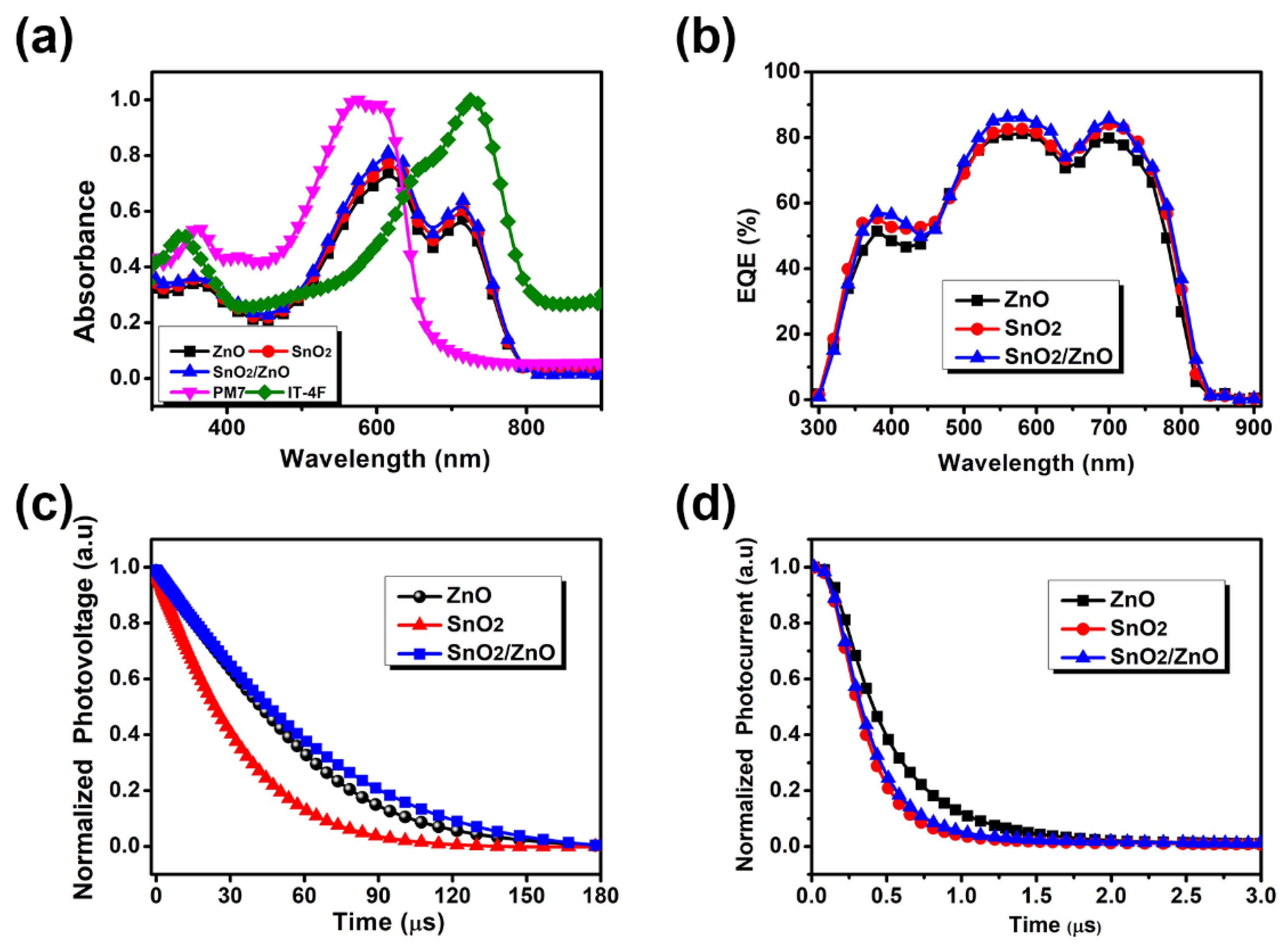
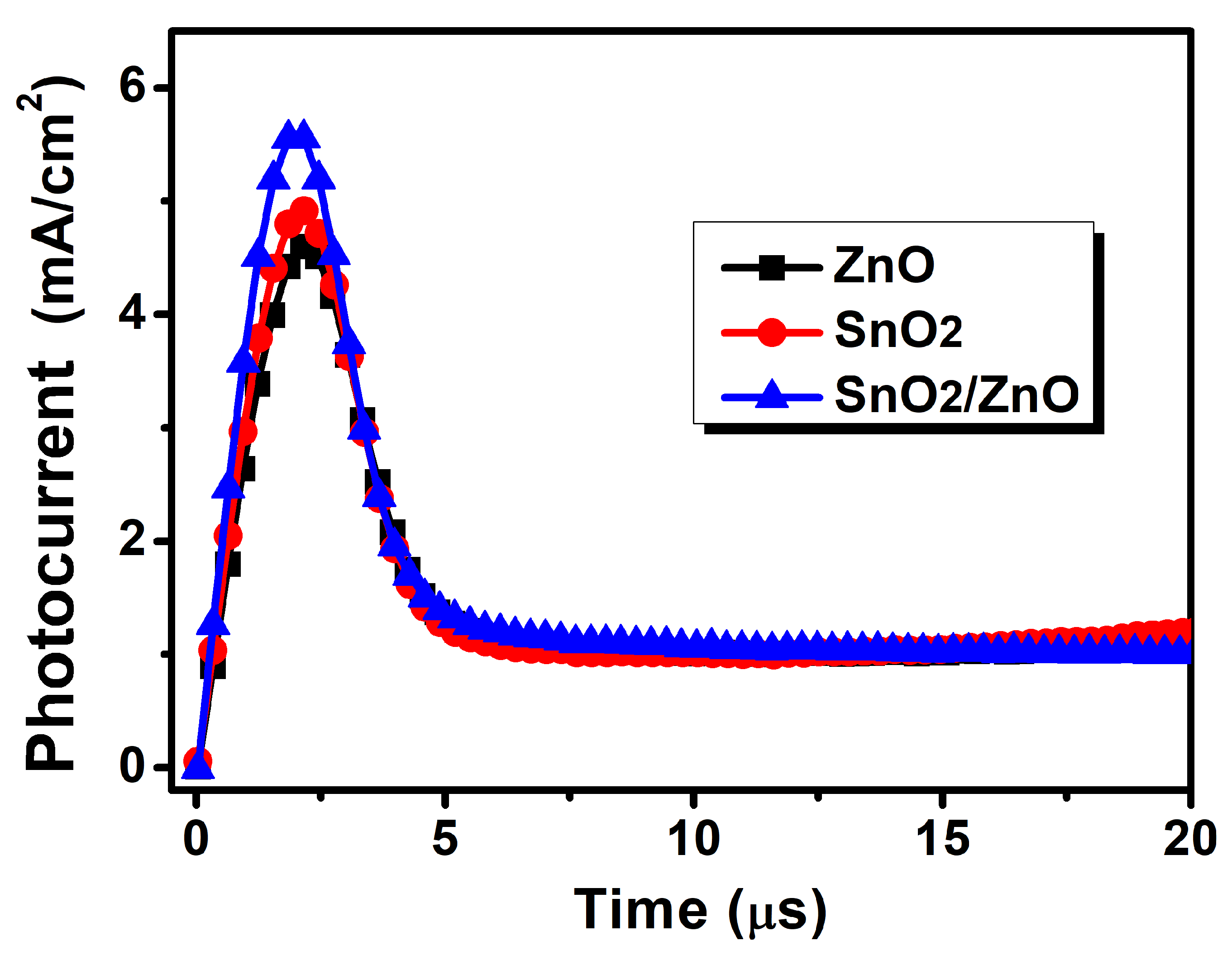
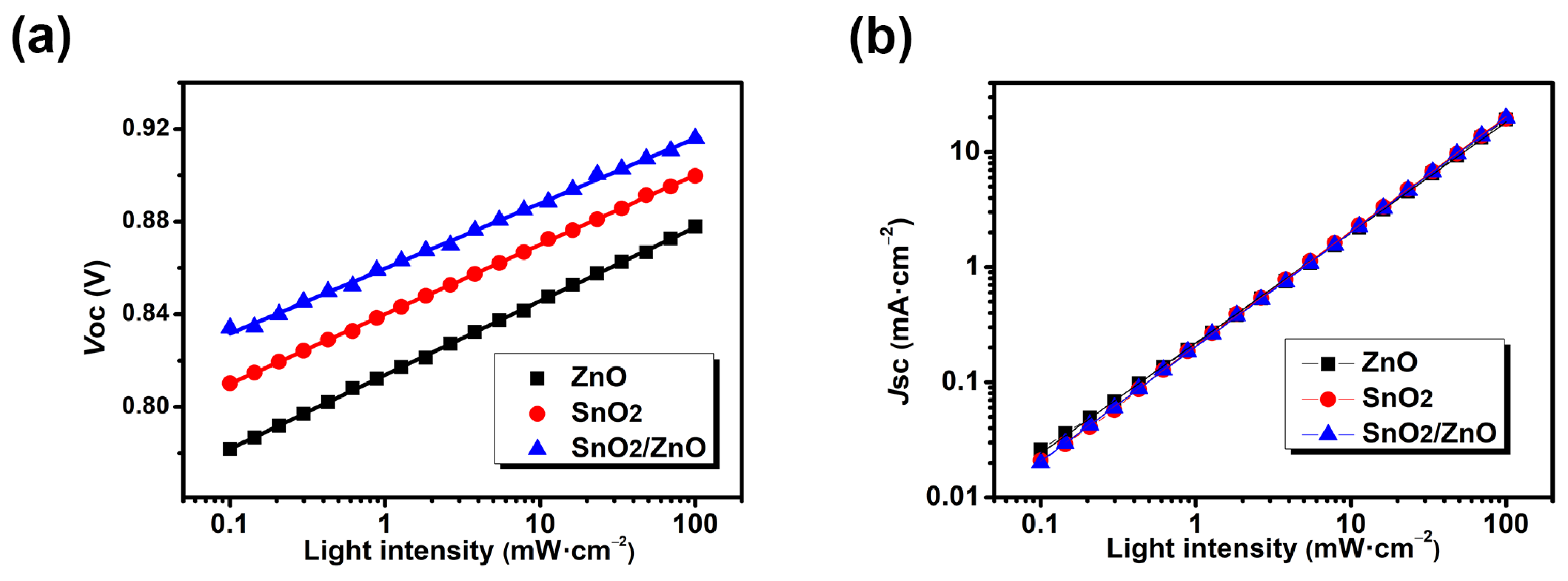
3.2. Characterization of Opto-Electronic Properties

The ultraviolet-visible absorption spectrum and external quantum efficiency spectra of the devices with ZnO, SnO2 and SnO2/ZnO (Figure 2) were measured to further understand the effect of the double-cathode buffer layer on the improvement of device performance. As the UV-Vis absorption spectrum shown in Figure 2a, there is no significant increase in light absorption for device based on SnO2/ZnO, indicating that the increase of JSC is not due to the improvement of the absorption of the film. As we all know, the improvement of JSC is associated with the ability to capture photons, the transmission and collection of charges [49]. Therefore, the improvement of JSC by the double cathode modification layer should be attributed to the improvement of charge transfer/collection in device. The EQE spectrum of devices with different cathode buffer layers were measured (Figure 2b). It can be seen that the curve of the double modification layer device is improved as a whole compared with that of the single modification layer devices, and the JSC calculated via integrating the EQE curves were in good agreement with the JSC obtained from the J-V curves (within 5% mismatch). Considering the results of UV-Vis absorption spectrum, we illustrate that the increase in JSC corresponds to the improvement of the charge transport and the reduce of the charge recombination.
Transient photovoltage (TPV) and transient photocurrent (TPC) measurements were applied to further study the charge transfer and charge extraction dynamics of the devices with different cathode buffer layers (ZnO, SnO2 and SnO2/ZnO).
TPV measurement can be utilized to analyze the charge recombination characteristic of the OSCs by exploring the decay lifetime via recording the voltage decay process under open circuit condition [50]. The TPV curve is recorded by keeping the device at open circuit voltage under bias-illumination [51,52]. On this basis, the device is applied an additional LED pulse to generate additional charges, and then the photovoltage decays exponentially. Meanwhile, the charge carrier lifetime can be calculated directly from the decay curve. In TPV analysis, the charge recombination time can be derived from a single exponential equation V = Aexp(−t/τ) (where A is a constant of the fitted peak height, t is the time and τ is the decay time) [52,53]. By fitting the TPV curves in Figure 2c, the transient photovoltage decay lifetime of ZnO, SnO2 and SnO2/ZnO modified devices is 69.18 μs, 34 μs and 77 μs, respectively (Table 3). The results suggest that the SnO2/ZnO layer is contributing to prolong the transient photovoltage decay lifetime of the OSCs. A short decay lifetime results from a premature recombination of charge carriers, which means the inefficient charge transport and low power conversion efficiency [54]. Compared to the device modified with single cathode buffer layer (ZnO or SnO2), the device with SnO2/ZnO have prolonged decay lifetime and exhibited higher device performance, which indicates the reduced charge carrier recombination due to the SnO2/ZnO modification. For the SnO2 modified device with the shortest decay lifetime, we speculate that the unfavorable energy level arrangement at the interface between SnO2 modified electrode and the active layer leads to charge accumulation and thus increased recombination.
TPC measurement is a method applied to obtain the charge extraction time τTPC of the OSCs via exponential fitting the normalized transient photocurrent decay curves derived from recording the current response of an optical step under short-circuit condition [55,56], and the short τTPC stands for good carrier transport and extraction [57]. By fitting the TPC curves in Figure 2d, the charge extraction time of devices modification by difference cathode buffer layer are summarized in Table 3. The charge extraction time for ZnO modification layer device is 0.45 μs, for SnO2 is 0.31 μs, and for double cathode modification layer device is 0.33 μs. Due to the vertical growth of SnO2 nanocrystal and the characteristic of hole blocking [58], the τTPC of the device modified with SnO2 is shorter than other devices. The device modified with ZnO film shows the longest charge extraction time, which could result from the ZnO film fabricated in this study is amorphous, the electron transport characteristic of which is inferior to crystalline ZnO film [59]. However, the device prepared by covering a SnO2 layer before preparing the ZnO film as cathode modification layer (SnO2/ZnO) shows a significant reduce in extraction time, compared to the device that directly fabricated ZnO film. The result indicates that the double cathode modification layer effectively enhances the efficiency of OSCs via improving charge collection at the electrode.
Through analyzing the characterization of carrier lifetime and charge extraction, we can conclude that the significant enhancement caused by double cathode modification layer (SnO2/ZnO) is mainly based on the improvement of the charge transfer and collection in the device, which is in good agreement with UV-vis and EQE results.
Photo-induced charge extraction linear increasing voltage (Photo-CELIV) measurement is applied to gain the carrier mobility of OSCs modified with ZnO, SnO2 and SnO2/ZnO [56,60], which is an effective research technology in revealing the internal charge transport characteristics of the device in operation. The corresponding photocurrent curves recorded by Photo-CELIV measurement are shown in Figure 3. A white LED light pulse is applied to the device tested in Photo-CELIV experiment, and then a linearly boosted signal is used to extract the photo-generated free charger inside the device [56,61]. During the Photo-CELIV test, the recorded photo-generated current curves show a rise, then slowly decrease, and finally tend to equilibrium. The charge carrier mobility can be calculated by the formula μ = 2d2/3Atmax2·1/(1 + 0.36Δj/jdisp) (where μ is the charge carrier mobility, A is the ramp rate, d is the active layer thickness (~120 nm), Δj is the peak current minus the displacement current, 1 + 0.36Δj/jdisp is an empirical correction for electric field redistribution, jdisp is the displacement current, tmax is the time when the current reaches the peak) [61]. The values of carrier mobility for the devices modified with ZnO, SnO2 and SnO2/ZnO are summarized in Table 3 calculated by the above formula. The device modified with these three kinds of buffer layers performed a charge carrier mobility of 8.10 × 10⁻⁵ cm2·V−1·s−1, 9.89 × 10⁻⁵ cm2·V−1·s−1 and 1.54 × 10⁻⁴ cm2·V−1·s−1, respectively, which reveals the improved carrier transport between the two electrodes, is one of the main mechanisms for the improving of device performance.
In order to further investigate the charge transport and carrier recombination properties, the relationship between VOC/JSC and light intensity (Plight) of the device was measured (Figure 4).
The dependence of VOC on Plight (see Figure 4a) is consistent with the logarithmic relationship: VOC∝βInPlight, where β = nκT/q, κ is the Boltzmann constant value, n is the ideal factor, T is the absolute temperature and q is the elementary charge. The ideal factor n is usually between 1 to 2, which means that β is usually between 1κT/q to 2κT/q. The β value symbolizes the competitive relationship between trap-assisted Shockley-Read-Hall (SRH) recombination and bimolecular recombination [57]. In general, the β values tend to 1κT/q suggests that bimolecular recombination is the dominant factor, whereas β values tend to 2κT/q indicates additional Shockley-Read-Hall (SRH) recombination have involved [62]. The lower β value means the Shockley-Read-Hall (SRH) recombination is the weaker factor in carrier recombination, and the SRH recombination is associated with interface defects that cause electrons and holes to be trapped and then recombined. The fitted lines for the devices modified with ZnO, SnO2 and SnO2/ZnO, showed the β values of 1.22κT/q, 1.16κT/q and 1.08κT/q, respectively (Table 4), indicating that SnO2/ZnO film contributes to the suppressed SRH recombination with less interface trap and more efficient charge transfer. Furthermore, the suppressed trap-assisted recombination results in higher FF and VOC, which is in good agreement with the TPV and TPC results.
In addition, the dependence of the JSC value on Plight were investigated for each device to further understand the bimolecular recombination and space charge accumulation in different devices. By fitting the lines in Figure 4b, the α values for devices modified with ZnO, SnO2 and SnO2/ZnO are 0.9594, 0.9977 and 0.9949, respectively. Following in theoretical consideration, the bimolecular recombination is associated by the α value in a logarithmic plot of JSC∝Plightα. Compared to the ZnO modified device, the α values of the SnO2 and SnO2/ZnO modified devices are more tend to 1 indicating the introduction of SnO2 could effectively suppress bimolecular recombination in the device. This may be due to the fact that SnO2 can effectively block holes [58] and improve the quality of ZnO film. Meanwhile, the addition of SnO2 provides a more efficient charge transfer channel for the transport of electrons, and improves the ability to extract charge at the cathode.
In briefly, SnO2/ZnO device showed relatively suppressed trap-assisted recombination and bimolecular recombination, which is the main reason for improvement of OSC performance, and in line with the TPV/TPC and UV-Vis results.

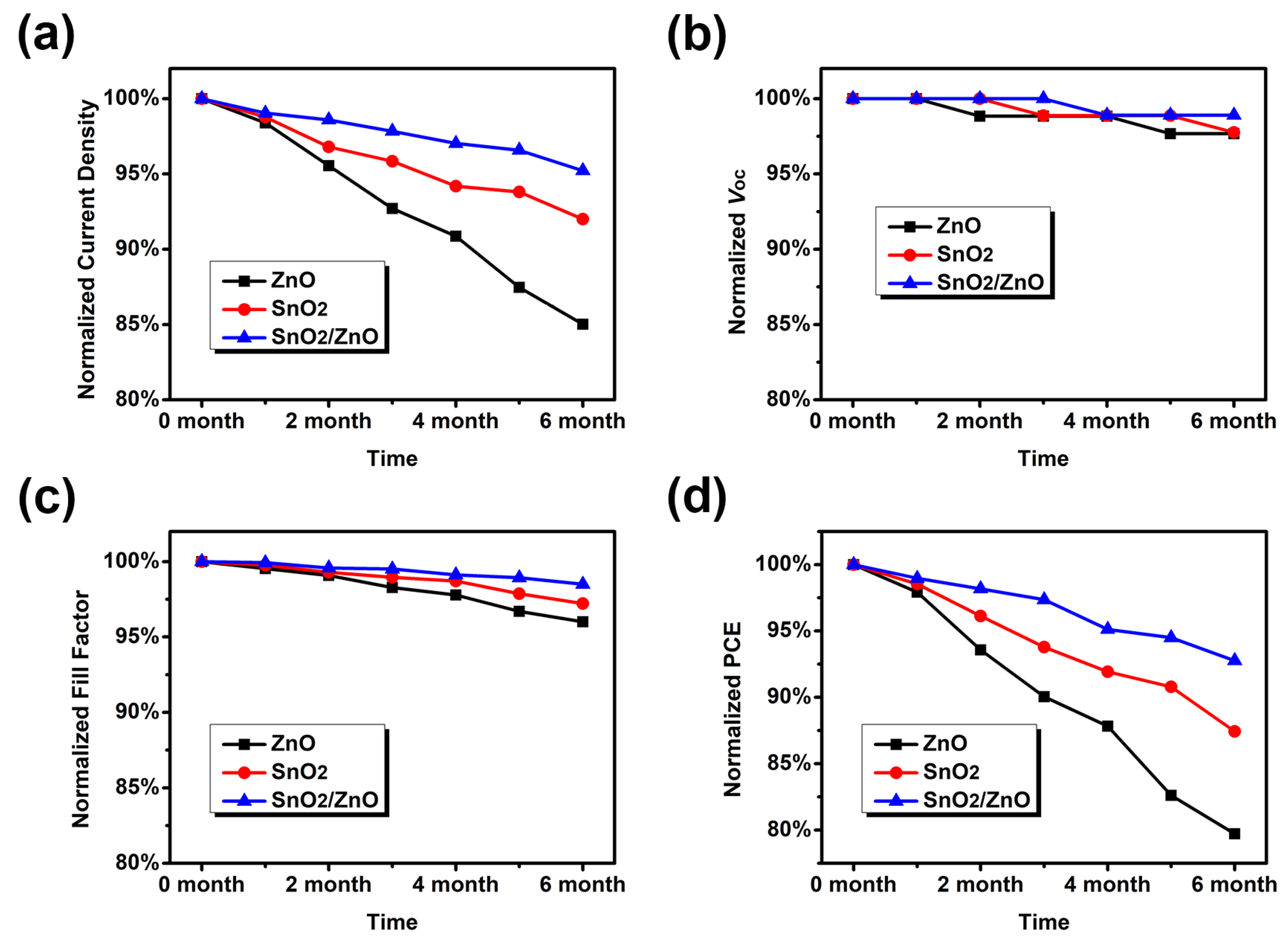
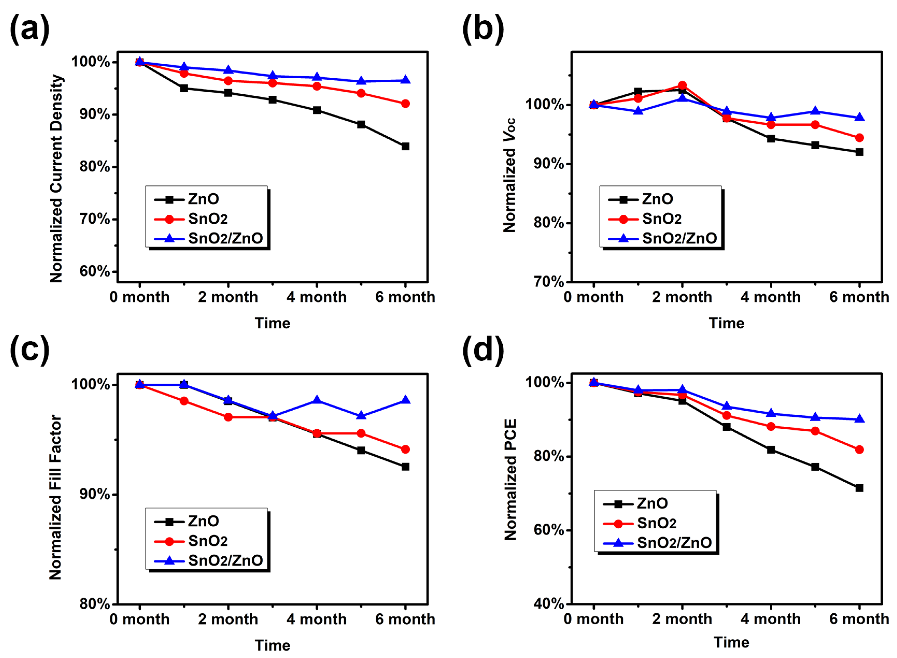
3.3. Improving Device Stability via SnO2/ZnO

There has been a lack of reports on the long-term stability of high-efficiency non-fullerene OSCs. Here we specifically tested and compared the long-term stability of devices based on three cathode modification layers. Figure 5 and Figure 6 show the dark-degradation curves of the photovoltaic characteristic parameters of the OSCs in nitrogen atmosphere and air conditions. As shown in Figure 5, the values of efficiency after six months for ZnO, SnO2 and (SnO2/ZnO) modified devices are decay to 80%, 87% and 93% of the initial device, respectively. The results suggest that the device modified with SnO2/ZnO film is able to avoid the direct contact between ITO and ZnO film effectively. Meanwhile, cover the SnO2 layer with a ZnO film can passivate the surface defects of SnO2 film and prevent downward penetration of molecules from the active layer into the electrode. In briefly, the improvement of stability for the OSCs from the introduction of SnO2/ZnO film as cathode modification layer results in the life extension of OSCs in nitrogen atmosphere.
To confirm the environmental stability of SnO2/ZnO modified device, we evaluated the stability for each device modified with single and double modification layers in air (Figure 6). As well known, oxygen could cause the oxidation of organic materials in the active layer, and the increase of the hole concentration inside the active layer may result in the carrier concentration to be out of balance [63]. In air atmosphere, the devices modified with ZnO, SnO2 and SnO2/ZnO showed decay efficiency to 68%, 72% and 83% of the initial device after six months, respectively. The device with SnO2/ZnO exhibited better efficiency stability compared to the devices with SnO2 and ZnO in air due to the denser film formed by the double cathode modification layer, which can efficiently prevent the water and oxygen molecules from entering into the device, so that effectively reduce the influence of water and oxygen in the air.
It is worth noting that the performance degradation of ZnO modified device is the most severe in both nitrogen atmosphere and air, and it is mainly due to the decline of JSC. This is most likely due to the strong absorption of UV by ZnO, which leads to the photodegradation of IT-4F, and the addition of SnO2 layer can effectively alleviate this problem [64]. In conclusion, the adoption of SnO2/ZnO films as cathode modification layer is proved to be an effective strategy to enhance the stability of OSCs, which could reduce the rate of dark-degradation both in nitrogen atmosphere and air condition.

4. Conclusions

In summary, we have prepared high-efficiency and high stability inversion OSCs based on PM7:IT-4F system by introducing the SnO2/ZnO film as a double cathode modification layer. Herein, we revealed the mechanism of improving the device performance and stability via SnO2/ZnO cathode modification layer. The advantages of both single ZnO and SnO2 films are reflected in SnO2/ZnO double cathode modified layer. Cover the ZnO on the SnO2 film efficiently passivate the surface defects of SnO2, and fabricate a SnO2 film before ZnO film is more conducive to electron transport and block holes. Compared to the single cathode modification layer, the SnO2/ZnO buffer layer enhances the PCE of OSCs obviously to 12.91% with a FF of 70%, a JSC of 20.04 mA/cm2 and a VOC of 0.92 V. The results obtained from charge transport and extraction study via TPV/TPC, Photo-CELIV measurements and dependence of VOC/JSC on light intensity imply the reducing energy barrier between the electrode and active layer and the reducing trap near the interface layer, which result in suppressed charge recombination, efficient charge transfer and collection near the active layer/(SnO2/ZnO) interface. Furthermore, the denser SnO2/ZnO modification layer, on one hand, prevents the downward infiltration of the active material into electrode, and on the other hand, efficiently reduces the immigration of water and oxygen into the interface between modification layer and active layer, which significantly slowed down the dark-degradation in both nitrogen and air atmosphere with a degradation rate of 7% in nitrogen, and 17% in air. Our work not only provides the method to fabricate OSCs with high efficiency and stability through double cathode modification layer, but more importantly elaborates the underlying mechanisms associated with improving the device efficiency and stability via cathode modification, which would provide new inspiration in the relevant studies.

Supplementary Materials

The following supporting information can be downloaded at: https://www.mdpi.com/article/10.3390/en15207643/s1, Figure S1: Atomic force microscopy (AFM) images of the ZnO (a,d), SnO2 (b,e) and SnO2/ZnO (c,f) films. In addition, the root-mean-square (RMS) roughness of the ZnO, SnO2 and SnO2/ZnO films are 2.95 nm, 1.76 nm and 1.94 nm, respectively; Figure S2: Ultraviolet photoelectron spectrometry (UPS) spectra of the ZnO, SnO2 and SnO2/ZnO films; Table S1: The secondary electron cutoff and work function derived from UPS spectra.

Author Contributions

Conceptualization, T.L. and T.D.; methodology, T.D.; validation, T.L.; formal analysis, T.D.; investigation, T.L.; resources, T.L.; data curation, T.L.; writing—original draft preparation, T.D.; writing—review and editing, T.L.; visualization, T.D.; supervision, T.L.; project administration, T.L.; funding acquisition, T.L. All authors have read and agreed to the published version of the manuscript.

Funding

Supported by the Research Foundation for Youth Scholars of Beijing Technology and Business University, grant number QNJJ2022-42.

Data Availability Statement

Not applicable.

Acknowledgments

The authors are very grateful for the support by the Research Foundation for Youth Scholars of Beijing Technology and Business University.

Conflicts of Interest

The authors declare no conflict of interest.

References

  1. Cheng, P.; Yan, C.; Wu, Y.; Wang, Y.; Qin, M.; An, Q.; Cao, J.; Huo, L.; Zhang, F.; Ding, L.; et al. Alloy Acceptor: Superior Alternative to PCBM toward Efficient and Stable Organic Solar Cells. Adv. Mater. 2016, 28, 8021–8028. [Google Scholar] [CrossRef]
  2. Cui, Y.; Xu, Y.; Yao, H.; Bi, P.; Hong, L.; Zhang, J.; Zu, Y.; Zhang, T.; Qin, J.; Ren, J.; et al. Single-Junction Organic Photovoltaic Cell with 19% Efficiency. Adv. Mater. 2021, 33, 2102420. [Google Scholar] [CrossRef] [PubMed]
  3. Qin, F.; Sun, L.; Chen, H.; Liu, Y.; Lu, X.; Wang, W.; Liu, T.; Dong, X.; Jiang, P.; Jiang, Y.; et al. 54 cm2 Large-Area Flexible Organic Solar Modules with Efficiency Above 13%. Adv. Mater. 2021, 33, 2103017. [Google Scholar] [CrossRef] [PubMed]
  4. Liu, Y.; Liu, G.; Xie, R.; Wang, Z.; Zhong, W.; Li, Y.; Huang, F.; Cao, Y. A Rational Design and Synthesis of Cross-Conjugated Small Molecule Acceptors Approaching High-Performance Fullerene-Free Polymer Solar Cells. Chem. Mater. 2018, 30, 4331–4342. [Google Scholar] [CrossRef]
  5. Zhu, C.; Meng, L.; Zhang, J.; Qin, S.; Lai, W.; Qiu, B.; Yuan, J.; Wan, Y.; Huang, W.; Li, Y. A Quinoxaline-Based D-A Copolymer Donor Achieving 17.62% Efficiency of Organic Solar Cells. Adv. Mater. 2021, 33, 2100474. [Google Scholar] [CrossRef] [PubMed]
  6. Yuan, J.; Zhang, Y.; Zhou, L.; Zhang, G.; Yip, H.; Lau, T.; Lu, X.; Zhu, C.; Peng, H.; Johnson, P.A.; et al. Single-Junction Organic Solar Cell with over 15% Efficiency Using Fused-Ring Acceptor with Electron-Deficient Core. Joule 2019, 3, 1140–1151. [Google Scholar] [CrossRef]
  7. Liu, Q.; Jiang, Y.; Jin, K.; Qin, J.; Xu, J.; Li, W.; Xiong, J.; Liu, J.; Xiao, Z.; Sun, K.; et al. 18% Efficiency organic solar cells. Sci. Bull. 2020, 65, 272–275. [Google Scholar] [CrossRef] [Green Version]
  8. Zhan, L.; Li, S.; Xia, X.; Li, Y.; Lu, X.; Zuo, L.; Shi, M.; Chen, H. Layer-by-Layer Processed Ternary Organic Photovoltaics with Efficiency over 18%. Adv. Mater. 2021, 33, 2007231. [Google Scholar] [CrossRef] [PubMed]
  9. Hong, L.; Yao, H.; Cui, Y.; Bi, P.; Zhang, T.; Cheng, Y.; Zu, Y.; Qin, J.; Yu, R.; Ge, Z.; et al. 18.5% Efficiency Organic Solar Cells with a Hybrid Planar/Bulk Heterojunction. Adv. Mater. 2021, 33, 2103091. [Google Scholar] [CrossRef]
  10. Wang, J.; Zheng, Z.; Zu, Y.; Wang, Y.; Liu, X.; Zhang, S.; Zhang, M.; Hou, J. A Tandem Organic Photovoltaic Cell with 19.6% Efficiency Enabled by Light Distribution Control. Adv. Mater. 2021, 33, 2102787. [Google Scholar] [CrossRef]
  11. Zhang, M.; Zhu, L.; Hao, T.; Zhou, G.; Qiu, C.; Zhao, Z.; Hartmann, N.; Xiao, B.; Zou, Y.; Feng, W.; et al. High-Efficiency Organic Photovoltaics using Eutectic Acceptor Fibrils to Achieve Current Amplification. Adv. Mater. 2021, 33, 2007177. [Google Scholar] [CrossRef] [PubMed]
  12. Lou, S.J.; Szarko, J.M.; Xu, T.; Yu, L.; Marks, T.J.; Chen, L.X. Effects of additives on the morphology of solution phase aggregates formed by active layer components of high-efficiency organic solar cells. J. Am. Chem. Soc. 2011, 133, 20661–20663. [Google Scholar] [CrossRef] [PubMed]
  13. Dai, T.; Li, X.; Zhang, Y.; Xu, D.; Geng, A.; Zhao, J.; Chen, X. Performance improvement of polymer solar cells with binary additives induced morphology optimization and interface modification simultaneously. Sol. Energy 2020, 201, 330–338. [Google Scholar] [CrossRef]
  14. Cai, C.; Yao, J.; Chen, L.; Yuan, Z.; Zhang, Z.; Hu, Y.; Zhao, X.; Zhang, Y.; Chen, Y.; Li, Y. Silicon Naphthalocyanine Tetraimides: Cathode Interlayer Materials for Highly Efficient Organic Solar Cells. Angew. Chem. Int. Ed. 2021, 60, 19053–19057. [Google Scholar] [CrossRef] [PubMed]
  15. Meng, H.; Liao, C.; Deng, M.; Xu, X.; Yu, L.; Peng, Q. 18.77% Efficiency Organic Solar Cells Promoted by Aqueous Solution Processed Cobalt(II) Acetate Hole Transporting Layer. Angew. Chem. Int. Ed. 2021, 60, 22554–22561. [Google Scholar] [CrossRef] [PubMed]
  16. Liu, L.; Chen, S.; Qu, Y.; Gao, X.; Han, L.; Lin, Z.; Yang, L.; Wang, W.; Zheng, N.; Liang, Y.; et al. Nanographene-Osmapentalyne Complexes as a Cathode Interlayer in Organic Solar Cells Enhance Efficiency over 18%. Adv. Mater. 2021, 33, 2101279. [Google Scholar] [CrossRef]
  17. Yu, Z.; Xia, Y.; Du, D.; Ouyang, J. PEDOT:PSS Films with Metallic Conductivity through a Treatment with Common Organic Solutions of Organic Salts and Their Application as a Transparent Electrode of Polymer Solar Cells. ACS Appl. Mater. Interfaces 2016, 8, 11629–11638. [Google Scholar] [CrossRef]
  18. Girotto, C.; Voroshazi, E.; Cheyns, D.; Heremans, P.; Rand, B.P. Solution-processed MoO3 thin films as a hole-injection layer for organic solar cells. ACS Appl. Mater. Interfaces 2011, 3, 3244–3247. [Google Scholar] [CrossRef]
  19. Aqoma, H.; Park, S.; Park, H.; Hadmojo, W.T.; Oh, S.; Nho, S.; Kim, D.; Seo, J.; Park, S.; Ryu, D.Y.; et al. 11% Organic Photovoltaic Devices Based on PTB7-Th: PC71BM Photoactive Layers and Irradiation-Assisted ZnO Electron Transport Layers. Adv. Sci. 2018, 5, 1700858. [Google Scholar] [CrossRef]
  20. Wen, X.; Fang, S.; Xu, Y.; Zheng, N.; Liu, L.; Xie, Z.; Würthner, F. Enhanced Electron Transportation by Dye Doping in Very Low-Temperature (<130 °C)-Processed Sol-Gel ZnO toward Flexible Organic Solar Cells. ACS Appl. Mater. Interfaces 2019, 11, 34151–34157. [Google Scholar] [CrossRef]
  21. You, J.; Chen, C.; Dou, L.; Murase, S.; Duan, H.; Hawks, S.A.; Xu, T.; Son, H.; Yu, L.; Li, G.; et al. Metal oxide nanoparticles as an electron-transport layer in high-performance and stable inverted polymer solar cells. Adv. Mater. 2012, 24, 5267–5272. [Google Scholar] [CrossRef] [PubMed]
  22. Brabec, C.J.; Shaheen, S.E.; Winder, C.; Sariciftci, N.S. Effect of LiF/metal electrodes on the performance of plastic solar cells. Appl. Phys. Lett. 2002, 80, 1288–1290. [Google Scholar] [CrossRef]
  23. Yu, S.; Yang, W.; Li, L.; Zhang, W. Improved Chemical Stability of ITO Transparent Anodes with a SnO2 Buffer Layer for Organic Solar Cells. Sol. Energy Mater. Sol. Cells 2016, 144, 652–656. [Google Scholar] [CrossRef]
  24. Lee, E.; Heo, S.; Han, Y.; Moon, D. An organic-inorganic hybrid interlayer for improved electron extraction in inverted polymer solar cells. J. Mater. Chem. C 2016, 4, 2463–2469. [Google Scholar] [CrossRef]
  25. He, R.; Yu, L.; Cai, P.; Peng, F.; Xu, J.; Ying, L.; Chen, J.; Yang, W.; Cao, Y. Narrow-Band-Gap Conjugated Polymers Based on 2,7-Dioctyl-Substituted Dibenzo[a,c]phenazine Derivatives for Polymer Solar Cells. Macromolecules 2014, 47, 2921–2928. [Google Scholar] [CrossRef]
  26. Xiong, S.; Hu, L.; Hu, L.; Sun, L.; Qin, F.; Liu, X.; Fahlman, M.; Zhou, Y. 12.5% Flexible Nonfullerene Solar Cells by Passivating the Chemical Interaction Between the Active Layer and Polymer Interfacial Layer. Adv. Mater. 2019, 31, 1806616. [Google Scholar] [CrossRef]
  27. Pan, F.; Sun, C.; Li, Y.; Tang, D.; Zou, Y.; Li, X.; Bai, S.; Wei, X.; Lv, M.; Chen, X.; et al. Solution-Processable n-Doped Graphene-Containing Cathode Interfacial Materials for High-Performance Organic Solar Cells. Energy Environ. Sci. 2019, 12, 3400–3411. [Google Scholar] [CrossRef]
  28. Zhang, Z.; Qi, B.; Jin, Z.; Chi, D.; Qi, Z.; Li, Y.; Wang, J. Perylene Diimides: A Thickness-Insensitive Cathode Interlayer for High Performance Polymer Solar Cells. Energy Environ. Sci. 2014, 7, 1966–1973. [Google Scholar] [CrossRef]
  29. Zhou, P.; Yang, Y.; Chen, X.; Zhang, Z.; Li, Y. Design of a Thiophene-fused Benzotriazole Unit as an Electron Acceptor to Build D-A Copolymers for Polymer Solar Cells. J. Mater. Chem. C 2017, 5, 2951–2957. [Google Scholar] [CrossRef]
  30. Jiang, T.; Yang, J.; Tao, Y.; Fan, C.; Xue, L.; Zhang, Z.; Li, H.; Li, Y.; Huang, W. Random Terpolymer with a Cost-effective Monomer and Comparable Efficiency to PTB7-Th for Bulk-heterojunction Polymer Solar Cells. Polym. Chem. 2016, 7, 926–932. [Google Scholar] [CrossRef]
  31. Uddin, A.; Upama, M.B.; Yi, H.; Duan, L. Encapsulation of Organic and Perovskite Solar Cells: A Review. Coatings 2019, 9, 65. [Google Scholar] [CrossRef] [Green Version]
  32. Burlingame, Q.; Ball, M.; Loo, Y. It’s time to focus on organic solar cell stability. Nat. Energy 2020, 5, 947–949. [Google Scholar] [CrossRef]
  33. Duan, L.; Uddin, A. Progress in Stability of Organic Solar Cells. Adv. Sci. 2020, 7, 1903259. [Google Scholar] [CrossRef] [Green Version]
  34. Hains, A.W.; Liu, J.; Martinson, A.B.F.; Irwin, M.D.; Marks, T.J. Anode Interfacial Tuning via Electron-Blocking/Hole-Transport Layers and Indium Tin Oxide Surface Treatment in Bulk-Heterojunction Organic Photovoltaic Cells. Adv. Funct. Mater. 2010, 20, 595–606. [Google Scholar] [CrossRef]
  35. Son, H.; Kim, S.; Kim, D. Critical Impact of Hole Transporting Layers and Back Electrode on the Stability of Flexible Organic Photovoltaic Module. Adv. Energy Mater. 2017, 7, 1601289. [Google Scholar] [CrossRef]
  36. Shaikh, S.F.; Kwon, H.; Yang, W.; Hwang, H.; Lee, H.; Lee, E.; Ma, S.; Moon, J. La2O3 interface modification of mesoporous TiO2 nanostructures enabling highly efficient perovskite solar cells. J. Mater. Chem. A 2016, 4, 15478–15485. [Google Scholar] [CrossRef]
  37. Shaikh, S.F.; Kwon, H.; Yang, W.; Mane, R.S.; Moon, J. Performance enhancement of mesoporous TiO2-based perovskite solar cells by ZnS ultrathin-interfacial modification layer. J. Alloys Compd. 2018, 738, 405–414. [Google Scholar] [CrossRef]
  38. Khan, U.; Iqbal, T.; Khan, M.; Wu, R. SnO2/ZnO as double electron transport layer for halide perovskite solar cells. Sol. Energy 2021, 223, 346–350. [Google Scholar] [CrossRef]
  39. Fan, Q.; Zhu, Q.; Xu, Z.; Su, W.; Chen, J.; Wu, J.; Guo, X.; Ma, W.; Zhang, M.; Li, Y. Chlorine substituted 2D-conjugated polymer for high-performance polymer solar cells with 13.1% efficiency via toluene processing. Nano Energy 2018, 48, 413–420. [Google Scholar] [CrossRef]
  40. Pan, M.; Lau, T.; Tang, Y.; Wu, Y.; Liu, T.; Li, K.; Chen, M.; Lu, X.; Ma, W.; Zhan, C. 16.7%-efficiency ternary blended organic photovoltaic cells with PCBM as the acceptor additive to increase the open-circuit voltage and phase purity. J. Mater. Chem. A 2019, 7, 20713–20722. [Google Scholar] [CrossRef]
  41. Zhang, Z.; Liu, X.; Yu, J.; Wang, H.; Zhang, M.; Yang, L.; Geng, R.; Cao, J.; Du, F.; Liu, F.; et al. Enhancing phase separation with a conformation-locked nonfullerene acceptor for over 14.4% efficiency solar cells. J. Mater. Chem. C 2019, 7, 13279–13286. [Google Scholar] [CrossRef]
  42. Wang, C.; Jiang, B.; Lu, J.; Cheng, M.; Jeng, R.; Lu, Y.; Chen, C.; Wong, K. A Near-Infrared Absorption Small Molecule Acceptor for High-Performance Semitransparent and Colorful Binary and Ternary Organic Photovoltaics. ChemSusChem 2020, 13, 903–913. [Google Scholar] [CrossRef] [PubMed]
  43. Cheng, J.; Zhang, L.; Jiang, H.; Yuan, D.; Wang, Q.; Cao, Y.; Chen, J. Investigation of halogen-free solvents towards high-performance additive-free non-fullerene organic solar cells. Org. Electron. 2020, 85, 105871. [Google Scholar] [CrossRef]
  44. Dai, T.; Li, X.; Zhang, Y.; Zhou, X.; Zhu, Y.; Zhou, J.; Xu, D.; Lin, T. Electric-Induced Degradation of Cathode Interface Layer in PM7:IT-4F Polymer Solar Cells. Sol. RRL 2021, 5, 2100151. [Google Scholar] [CrossRef]
  45. Zhou, X.; Dai, T.; Li, X.; Yan, Y.; Xiong, W.; Lin, T.; Zhou, J.; Xu, D.; Zhu, Y.; Zhao, J.; et al. Improved Charge Transport and Reduced Carrier Recombination of Nonfullerene Organic Solar Cells with the Binary Solvent. ACS Appl. Energy Mater. 2021, 4, 8175–8182. [Google Scholar] [CrossRef]
  46. Tran, V.; Eom, S.; Yoon, S.; Kim, S.; Lee, S. Enhancing device performance of inverted organic solar cells with SnO2/Cs2CO3 as dual electron transport layers. Org. Electron. 2019, 68, 85–95. [Google Scholar] [CrossRef]
  47. Ai, Y.; Liu, W.; Shou, C.; Yan, J.; Li, N.; Yang, Z.; Song, W.; Yan, B.; Sheng, J.; Ye, J. SnO2 surface defects tuned by (NH4)2S for high-efficiency perovskite solar cells. Sol. Energy 2019, 194, 541–547. [Google Scholar] [CrossRef]
  48. Xiong, Y.; Lin, Y.; Wang, X.; Zhao, Y.; Tian, J. Defect engineering on SnO2 nanomaterials for enhanced gas sensing performances. Adv. Powder Mater. 2022, 1, 100033. [Google Scholar] [CrossRef]
  49. An, Q.; Ma, X.; Gao, J.; Zhang, F. Solvent additive-free ternary polymer solar cells with 16.27% efficiency. Sci. Bull. 2019, 64, 504–506. [Google Scholar] [CrossRef] [Green Version]
  50. Chen, J.; Zhang, L.; Jiang, X.; Gao, K.; Liu, F.; Gong, X.; Chen, J.; Cao, Y. Using o-Chlorobenzaldehyde as a Fast Removable Solvent Additive during Spin-Coating PTB7-Based Active Layers: High Efficiency Thick-Film Polymer Solar Cells. Adv. Energy Mater. 2017, 7, 1601344. [Google Scholar] [CrossRef]
  51. Xiao, J.; Chen, Z.; Zhang, G.; Li, Q.; Yin, Q.; Jiang, X.; Huang, F.; Xu, Y.; Yip, H.; Cao, Y. Efficient device engineering for inverted non-fullerene organic solar cells with low energy loss. J. Mater. Chem. C 2018, 6, 4457–4463. [Google Scholar] [CrossRef]
  52. Blom, P.W.M.; Mihailetchi, V.D.; Koster, L.J.A.; Markov, D.E. Device Physics of Polymer:Fullerene Bulk Heterojunction Solar Cells. Adv. Mater. 2007, 19, 1551–1566. [Google Scholar] [CrossRef] [Green Version]
  53. Li, Z.; Gao, F.; Greenham, N.C.; McNeill, C.R. Comparison of the Operation of Polymer/Fullerene, Polymer/Polymer, and Polymer/Nanocrystal Solar Cells: A Transient Photocurrent and Photovoltage Study. Adv. Funct. Mater. 2011, 21, 1419–1431. [Google Scholar] [CrossRef]
  54. Chatri, A.R.; Torabi, S.; Corre, V.M.L.; Koster, L.J.A. Impact of Electrodes on Recombination in Bulk Heterojunction Organic Solar Cells. ACS Appl. Mater. Interfaces 2018, 10, 12013–12020. [Google Scholar] [CrossRef] [Green Version]
  55. Soci, C.; Moses, D.; Xu, Q.; Heeger, A.J. Charge-carrier Relaxation Dynamics in Highly Ordered Poly(p-phenylene vinylene): Effects of Carrier Bimolecular Recombination and Trapping. Phys. Rev. B 2005, 72, 245204. [Google Scholar] [CrossRef] [Green Version]
  56. Stephen, M.; Genevičius, K.; Juška, G.; Arlauskas, K.; Hiorns, R.C. Charge transport and its characterization using photo-CELIV in bulk heterojunction solar cells. Polym. Int. 2017, 66, 13–25. [Google Scholar] [CrossRef]
  57. Cowan, S.R.; Roy, A.; Heeger, A.J. Recombination in polymer-fullerene bulk heterojunction solar cells. Phys. Rev. B 2010, 82, 245207. [Google Scholar] [CrossRef] [Green Version]
  58. Huang, S.; Tang, Y.; Yu, A.; Wang, Y.; Shen, S.; Kang, B.; Silva, S.R.P.; Lu, G. Solution-processed SnO2 Nanoparticle Interfacial Layers for Efficient Electron Transport in ZnO-based Polymer Solar Cells. Org. Electron. 2018, 62, 373–381. [Google Scholar] [CrossRef]
  59. Yin, Z.; Zheng, Q.; Chen, S.; Cai, D. Interface Control of Semiconducting Metal Oxide Layers for Efficient and Stable Inverted Polymer Solar Cells with Open-Circuit Voltages over 1.0 Volt. ACS Appl. Mater. Interfaces 2013, 5, 9015–9025. [Google Scholar] [CrossRef] [PubMed]
  60. Sandberg, O.J.; Nyman, M. Charge extraction by a linearly increasing voltage of photo-generated carriers: The influence of two mobile carrier types, bimolecular recombination, and series resistance. Org. Electron. 2019, 64, 97–103. [Google Scholar] [CrossRef]
  61. Neukom, M.; Züfle, S.; Jenatsch, S.; Ruhstaller, B. Opto-electronic characterization of third-generation solar cells. Sci. Technol. Adv. Mater. 2018, 19, 291–316. [Google Scholar] [CrossRef] [PubMed] [Green Version]
  62. Song, K.; Singh, R.; Lee, J.; Sin, D.; Lee, H.; Cho, K. Propeller-shaped small molecule acceptors containing a 9,9′-spirobifluorene core with imide-linked perylene diimides for non-fullerene organic solar cells. J. Mater. Chem. C 2016, 4, 10610–10615. [Google Scholar] [CrossRef]
  63. Dkhil, S.B.; Pfannmöller, M.; Schröder, R.R.; Alkarsifi, R.; Gaceur, M.; Köntges, W.; Heidari, H.; Bals, S.; Margeat, O.; Ackermann, J.; et al. Interplay of Interfacial Layers and Blend Composition To Reduce Thermal Degradation of Polymer Solar Cells at High Temperature. ACS Appl. Mater. Interfaces 2018, 10, 3874–3884. [Google Scholar] [CrossRef] [PubMed]
  64. Jiang, Y.; Sun, L.; Jiang, F.; Xie, C.; Hu, L.; Dong, X.; Qin, F.; Liu, T.; Hu, L.; Jiang, X.; et al. Photocatalytic effect of ZnO on the stability of nonfullerene acceptors and its mitigation by SnO2 for nonfullerene organic solar cells. Mater. Horiz. 2019, 6, 1438–1443. [Google Scholar] [CrossRef]
Figure 1. (a) Device architecture and photoactive materials; (b) PM7 (where n indicates the degree of polymerization); (c) IT-4F; (d) The J-V characteristic curves of the OSCs with ZnO, SnO2 and SnO2/ZnO cathode buffer layers.
Energies 15 07643 g001
Figure 2. (a) UV-Vis absorption spectra and (b) the EQE spectra of the devices; Normalized (c) TPV and (d) TPC decay curves of the device with different cathode buffer layers.
Energies 15 07643 g002
Figure 3. Photo-CELIV curves of the device with different cathode buffer layers.
Energies 15 07643 g003
Figure 4. The light intensity dependence of (a) VOC and (b) JSC of the device with different cathode buffer layers.
Energies 15 07643 g004
Figure 5. The normalized photovoltaic performance curves of devices in purity nitrogen atmosphere: (a) for JSC; (b) for VOC; (c) for FF; (d) for PCE.
Energies 15 07643 g005
Figure 6. The normalized photovoltaic performance curves of devices in air: (a) for JSC; (b) for VOC; (c) for FF; (d) for PCE.
Energies 15 07643 g006
Table 1. Photovoltaic performance of devices with ZnO, SnO2 and SnO2/ZnO films.
Jsc (mA/cm2)Voc (V)FFPCE (%)
ZnO19.22 a
(19.06 b ± 0.15)
0.88 a
(0.88 b ± 0.01)
0.67 a
(0.66 b ± 0.01)
11.45 a
(11.42 b ± 0.04)
SnO219.45 a
(19.28 b ± 0.12)
0.90 a
(0.90 b ± 0.01)
0.68 a
(0.68 b ± 0.01)
12.03 a
(11.92 b ± 0.12)
SnO2/ZnO20.04 a
(19.72 b ± 0.29)
0.92 a
(0.91 b ± 0.01)
0.70 a
(0.69 b ± 0.01)
12.91 a
(12.66 b ± 0.24)
a For champion device. b For average of 30 devices.
Table 2. Photovoltaic parameters of devices in relevant research.
Device StructureJsc
(mA/cm2)
Voc
(V)
FFPCE
(%)
ITO/NP-ZnO/PM7:IT-4F/MoO3/Al [39]20.90.880.7113.1
ITO/PEDOT:PSS/PM7:IT-4F/PDINO/Al [40]20.50.850.7713.4
ITO/ZnO/PM7:IT-4F/MoO3/Ag [41]20.210.860.7212.48
ITO/ZnO/PM7:IT-4F/MoO3/Ag [42]15.80.900.649.1
ITO/PEDOT:PSS/PM7:IT-4F/PFN-Br/Al [43]17.140.930.7311.72
ITO/PEDOT:PSS/PM7:IT-4F/PFN-Br/Al [44]20.480.870.559.77
ITO/ZnO/PM7:IT-4F/MoO3/Ag [45]20.470.900.6912.74
This work20.040.920.7012.91
Table 3. The parameters derived from TPV/TPC and Photo-CELIV measurements for the devices with different cathode buffer layers.
τTPV (μs)τTPC (μs)Carrier Mobility (cm2·V−1·s−1)
ZnO69.180.458.10 × 10−5
SnO234.270.319.89 × 10−5
SnO2/ZnO77.420.331.54 × 10−4
Table 4. The values of the light intensity dependence of JSC and VOC of the device with different cathode buffer layers.
αβ (κT/q)
ZnO0.95941.22
SnO20.99771.16
SnO2/ZnO0.99491.08
Publisher’s Note: MDPI stays neutral with regard to jurisdictional claims in published maps and institutional affiliations.

