Article

Evaluation and Optimization of heat Pump Combined District Heating System: A Case Study of China

1
School of Environmental Science and Engineering, Tianjin University, Tianjin 300350, China
2
China Electric Power Research Institute, Beijing 100192, China
3
State Grid Beijing Electric Power Company, Beijing 100031, China
*
Author to whom correspondence should be addressed.
Energies 2022, 15(20), 7622; https://doi.org/10.3390/en15207622
Submission received: 2 September 2022 / Revised: 9 October 2022 / Accepted: 12 October 2022 / Published: 15 October 2022
(This article belongs to the Special Issue Energy Conservation and Carbon Mitigation Technology of Buildings)

Abstract

:
The district heating area in China is continuously increasing, which brings an increase in district heating load. In order to solve the shortage of heating power and realize the carbon neutral target, this study proposes two retrofit schemes for district heating system by integrating air source heat pump and water source heat pump, respectively. Mathematical models are established to study the performance of the integrated systems and a bilevel optimization model is proposed to optimize them. The results show that the air source heat pump combined district heating system has better performance compared to the conventional system, which reduces 50% energy consumption, 10.8% carbon emissions and achieves better economy. The dynamic coupling property of the district heating network and power grid are also considered, and the results indicate that the introduction of air source heat pump can effectively improve the efficiency and stability of power grid and reduce the seasonal fluctuation. The potential of large-scale application of air source heat pump combined system in Beijing is evaluated. The results reveal that retrofit scheme of integrating air source heat pumps into district heating system can cover 2930 MW heating load and bring 362 million Chinese Yuan profit by reducing 219,000 tons of carbon emissions and 539,000 tons of standard coal consumption in 2025.

1. Introduction

China has set a national political goal of achieving carbon peaking by 2030 and carbon neutrality by 2060, which involves reforms to reduce energy consumption and carbon emissions in all walks of life, including transportation, buildings, industry, and energy production [1]. In building sector, the energy consumption of space heating accounts for 21% of building energy consumption [2]. China has built the world’s largest district heating (DH) system with 426,000 km of networks by 2020, covering nearly all the cities in Northern China [3], and the main heat sources are coal-fired boilers, gas-fired boilers, combined power and heat (CHP) plants, etc. In order to reduce the energy consumption and carbon emissions in the DH sector, the Chinese government has implemented many initiatives, such as shutting down coal-fired boilers and switching to electric heating and gas heating [4]. Although these measures have led to a reduction in carbon emissions in the DH sector, they have also led to the shortage of heat sources, and meanwhile the ongoing urbanization has been drawing an increasing heating demand in China. Therefore, China’s DH system is facing a challenge of finding low-carbon, clean and efficient way to supplement its heat shortage. In Europe, Lund et al. [5,6,7] proposed the concept of the 4th generation district heating (GDH) system, i.e., DH system with renewable energy, low-temperature water supply, and decarbonization. Jodeiri et al. [2,8] reviewed studies, achievements, technical aspects and challenges related to the DH system transition towards the 4th generation, and they found that heat pumps would play a crucial role in the integration of renewable energy sources and industrial waste heat into DH systems. Electric-driven heat pump (HP) is a device that can use renewable energy to produce heat. Therefore, integrating electric driven heat pumps into DH system is a feasible way to solve the problem of low-carbon heat source shortage and transform to the 4th GDH.
Ziemele et al. [9,10] proposed several technical pathways for the transition to the 4th GDH system, and their study proved that HPs would play an important role in the transition to achieve a balance between energy savings and investment costs. Averfalk et al. [11] compared heat supply costs for a set of different heat supply sources at two pre-determined temperature levels and the results indicated that with decreasing distribution temperatures, the required installing capacity of HPs was reduced, and HPs were able to cover more of the total heat load. Lund et al. [12] discussed fairness and effectiveness of the tariffs introduced by district heating supply companies with penalties for high return temperatures and benefits for low return temperatures, and some recommendations are given to improve the tariffs. Li et al. [13] studied possibilities, bottlenecks and challenges of the transition process to the 4th GDH, and the potential of HPs in application of low-level heat sources, supply of domestic hot water and space heating was illustrated. Su et al. [14] proposed a spatial system analysis method as a tool for heating-solution feasibility evaluation, and the findings proved that air source heat pumps for space heating had great potential in both south and north rural China. A lot of scholars have studied the economic potential of using HPs for DH. Bjarne Bach et al. [15] analyzed the feasibility for the integration of large-scale HPs in the DH systems of Copenhagen by considering different heat sources and connections. Their study showed that the integration was profitable for the system and connecting HPs to the distribution network was more competitive than to the transmission network. Lund et al. [16] studied the potential for introducing large-scale HPs into DH in Denmark and concluded that the application of HPs could bring great socioeconomic benefits of 100 million euros each year in 2025. Zhang et al. [17] analyzed the economic performance of using HPs in the decarbonization of the heating sector in UK. They found that using only HPs was less cost-effective than integrating HPs with gas boilers, and DH system was the least economical way by taking infrastructure costs into consideration.
As more and more countries have put forward their national political goal of decarbonization, renewables are becoming a more important power source in the national grid [18]. During the transition to the future power system, electric driven HPs may play an important role in realizing the flexibility of power grid [19]. The potential of HPs to use renewable energy and reach lower carbon emissions has also been explored. Sun et al. [20] studied a DH system integrated with industrial exhausted heat using electric driven HPs, and they concluded that HPs contributed to recovering waste heat, improving the thermal performance and financial benefit of the DH system. Blarke and Lund [21] investigated the performance of large-scale HP units coupled with CHP plants in DH system. The results indicated that the integration of HPs with existing DH system might be the key to introduce a large number of renewables into the power grid and promote the integration of heating and power sector. In addition, many studies [22,23,24,25] have also proved that the introduction of HPs into energy systems is economically advantageous and can reduce carbon emissions.
Although numerous studies have shown that integrating HPs into DH system could bring economic benefits and contribute to carbon mitigation as well as the transition to the 4th GDH, most of the studies focused only on the national energy system and strategies in Europe, where the energy structure, population size and infrastructure situation is totally different from that of China. For China it is still quite a challenge to realize the 4th GDH transition with the existing large-scale DH network of nearly 426,000 km. The supply temperature of the primary network is usually more than 100 °C, which is clearly too high for the supply temperature of HPs. In addition, the coefficient of performance (COP) of HP will decrease significantly with the increase of supply temperature. In this case, it is more reasonable to integrate HPs into the secondary network in the DH substations. Song et al. [26] proposed an absorption heat pump-based (AHP) system to integrate geothermal water into the secondary network in DH substations without decreasing supply temperature of the primary network. They used MATLAB [27] to simulate the proposed system and the whole substation, and a real business center in Tianjin was taken as a case for further analysis. The results of their study indicated that using AHP in DH could save 8% of the annual cost and reduce 25.6% of carbon emissions. Shu et al. [28] investigated the impact factors for energy saving of seawater source heat pump integrated DH system, and concluded that the energy saving would be directly impacted by the heating district radius and the design parameters of seawater source heat pump. However, the impact on the power grid caused by the application of electric driven HPs is often neglected, yet this would be critical to the integration of HPs into DH system.
Therefore, based on the idea of integrating HPs into the secondary network of DH systems, this study investigates the systematic retrofitting scheme of introducing air-source heat pump (ASHP) and water-source heat pump (WSHP), respectively, into DH substations to satisfy the increasing heating load demand. The performance of these two retrofitting schemes is studied and the potential of large-scale application of the proposed system is evaluated. Section 2 gives the configuration and mathematical models of the system. The optimization model is also described in this chapter. In Section 3 an onsite DH substation in Beijing is selected to study the performance of the proposed system and the results are presented and discussed in Section 4. The conclusions are given in Section 5.
2. System and Model Construction

The system construction of integration ASHP and WSHP, respectively, into DH system is studied and the mathematical models are built. A bilevel optimization model [29] focusing on energy saving and economic costs is developed, and solved by the particle swarm optimization algorithm [30].

2.1. System Description

2.1.1. ASHP Combined DH System

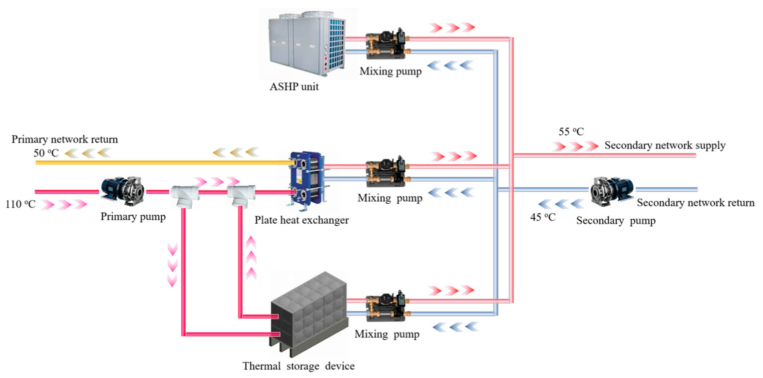
The retrofit scheme of introducing ASHP into the exiting DH system is developed to fill the heating gap caused by the increasing of heating demand, and the system schematic diagram is shown in Figure 1. The proposed system mainly consists of ASHP, thermal storage (TS) device and the existing plate heat exchanger of the heating substation. ASHP units, plate heat exchanger and TS device are connected in parallel, which allows them to work together or separately according to the heating demand. The supply water of the primary network is used for TS device charging during the low heating demand period, which can take full advantage of the high temperature hot water (designed at 110 °C).
To reach the lower operation costs, the operation modes of the system are developed as follows considering COP of ASHP, peak and valley load tariffs and heat price.
  • ASHP priority mode:
    • ASHP units is turned on in priority to meet the heat demand.
    • Heat storage tank discharge thermal storage when heat demand exceeds the heating capacity of ASHP.
    • When the heat demand exceeds ASHP’s heating capacity, and heat storage tank cannot release heat anymore, plate heat exchanger is used for heat supply together with ASHP.
    • The heat storage tank should be charged by primary network when there is surplus of the primary network supply.
  • Plate heat exchanger priority mode:
    • Plate heat exchanger is turned on in priority to meet the heat demand.
    • Heat storage tank discharge thermal when heat demand exceeds the heating capacity of the plate heat exchanger.
    • When the heat demand exceeds the heating capacity of plate heat exchanger, and heat storage tank cannot release heat anymore, ASHP units are turned on for heat supply together with plate heat exchanger.
    • The heat storage tank should be charged by primary network when there is a surplus of the primary network supply.
  • Control strategy of TS device:
    • TS device is charged by the primary network when the plate heat exchanger is unoccupied or operates at partial load.
    • TS device release heat when there is heating power deficit of the system.

2.1.2. WSHP Combined DH System

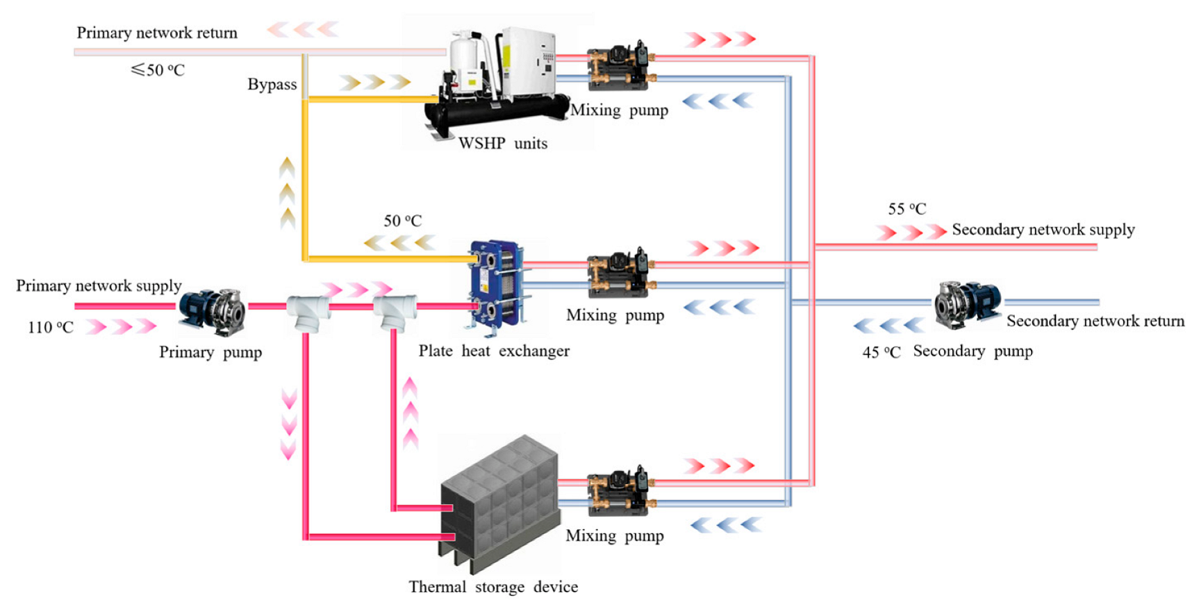
WSHP retrofit scheme is to reuse the return water of the primary network as the heat source to boost the return water temperature of the secondary network. It can enlarge the temperature difference between the supply and return water of the primary network, and reduce the transmission energy consumption. The schematic diagram is illustrated in Figure 2. Compared with the retrofit scheme of ASHP system, the heat replenished by the WSHP is mainly from the primary network and the operation costs are higher. Therefore, in view of the energy conversion costs of electricity to heat, the operation strategies of WSHP-based system are made. The heat from the primary network is used in priority through the plate heat exchanger, while the WSHP and TS are used as auxiliary heating devices. The TS is charged by the primary network when the plate heat exchanger is unoccupied or operates at partial load.

2.2. Mathematical Model

2.2.1. Air Source Heat Pump Unit

As the COP and heating capacity of the ASHP are related to the ambient temperature, output temperature of condenser and load factor, etc., DOE-2 [31] model is used to analyze the dynamic performance of ASHP. The performance of ASHP can be evaluated by the following equations:
C A P a = a 1 + b 1 × T a i r + c 1 × T a i r 2 + d 1 × T a c ,   o u t   + e 1 × T a c ,   o u t   2 + f 1 × T a i r × T a c ,   o u t C O P P L R a = a 2 + b 2 × P L R a + c 2 × P L R a 2 P L R a = C A P a / C A P a , r C O P a = C O P a , r × C O P P L R a
where, C A P a is the actual heating capacity of ASHP, kW, C O P a is the actual COP of ASHP,   C A P a , r is the rated heating capacity of ASHP, kW, C O P a , r is the rated COP of ASHP, C O P P L R a is the ratio of C O P a and C O P a , r , P L R a is the load factor of ASHP, T a i r is the ambient temperature, °C, and T a c , o u t is the output temperature of condenser, °C.
Considering the reduction of carbon emissions, the ASHP should be operated on the condition that the C O P a is higher than 3 (COP should be greater than the ratio of the carbon emission factors of natural gas to electricity). In addition, the coefficients of a 1 ~ f 1 and a 2 ~ c 2 are obtained from the heat pump heating performance data and power consumption data provided by the manufacturer.
The power consumption of ASHP can be calculated by:
W a = C A P a / C O P a
where W a represents the ASHP actual power consumption, kW.

2.2.2. Water Source Heat Pump Unit

Similar to the ASHP model, the WSHP model can be expressed as:
C A P w = a 3 + b 3 × T w c , o u t + c 3 × T w c , o u t 2 + d 3 × G w c + e 3 × G w c 2 + f 3 × T w e , i n + g 3 × T w e , i n 2 + h 3 × G w e + i 3 × G w e 2 C O P w = a 4 + b 4 × T w c , o u t + c 4 × T w c , o u t 2 + d 4 × G w c + e 4 × G w c 2 + f 4 × T w e , i n + g 4 × T w e , i n 2 + h 4 × G w e + i 4 × G w e 2
where C A P w is the heating capacity of WSHP, kW, C O P w is the COP of WSHP, T w e , i n and T w c , o u t are the input and output water temperature of the WSHP condenser, °C, G w e and G w c are the mass flow rate of water entering the WSHP evaporator and condenser, kg/h. The coefficients of a 3 ~ i 3 and a 4 ~ i 4 are obtained from the manufacturer.
The outputs of WSHP module can be expressed as:
W w = C A P w / C O P w T w e , o u t = T w e , i n C A P w W a G w e c p , w e
where W w represents the power consumption rate of WSHP, kW, T w e , o u t is the output water temperature of WSHP evaporator, °C, c p , w e is the specific heat capacity of water in evaporator, kJ/(kg·°C).

2.2.3. Plate Heat Exchanger

The plate heat exchanger model is developed to analyze the heat exchange between the secondary and primary network, so a steady-state heat transfer model is adopted and can be calculated as follows:
1 η p Q 1 = Q 2 = Q 3 Q 1 = c s × G s × T sg T sh Q 2 = c l × G l × T l g T l h Q 3 = K F Δ T η p 0 , 1
where Q 1 , Q 2 , Q 3 are the heat transfer rate calculated from primary network side, secondary network side and the plate heat exchanger side, respectively, kW, and η p is the heat loss rate of the heat exchanger. G s and c s , G l and c l are the mass flow rate, kg/s, and specific heat capacity, kJ/(kg·°C), of the water in primary and secondary network, while T sg , T sh , T l g and T l h are the supply and return water temperature of primary and secondary network, °C. K is the heat transfer coefficient, W/(m2·K), F and Δ T are the heat transfer area, m2, and average temperature difference, °C, of plate heat exchanger.

2.2.4. Thermal Storage Device

The mathematical model of TS device is established as follows:
Q T S τ = Q T S τ 1 1 β + α η c P c 1 α P d η d Δ τ η c 0 , 1 η d 0 , 1 α = 0 , 1 Φ T S m i n Φ T S τ Φ T S m a x P c = g c T s g τ , T T S τ , G s g τ P d = g d T l h τ , T T S τ , G l h τ
where Q T S τ represents the stored thermal energy, kW, in TS at moment τ , β is the heat loss rate of TS, α is used to illustrate whether the TS is charging or discharging. η c , η d , P c and P d are the charging and discharging efficiency and power of TS, kW. Φ T S is the heat storage of TS, Φ T S m a x and Φ T S m i n are the upper and lower limits of Φ T S , GJ.  T s g τ , T l h τ , G s g τ and G l h τ are the temperature, °C, and mass flow rate, kg/s, of primary network and secondary network entering TS, and T T S τ is the temperature, °C, of working fluid in TS at moment τ .

2.2.5. Flow Mixer

The schematic diagram of flow mixer is shown in Figure 3. Hot water from heat pumps, heat exchanger or TS is mixed with the return water from the secondary network to control the temperature and mass flow rate of supply water in the secondary network.
The model of flow mixer can be expressed as:
G = G 1 + G 2 G × T = G 1 × T 1 + G 2 × T 2

2.3. Optimization Model

A bilevel optimization model is built to solve the multi-objective, multi-variable, multi-constraint and multi-step decision-making problem. The bilevel optimization model divides the optimization process into two optimization models consisting of a design optimization model (upper level) and an operation optimization model (lower level). The outputs from the upper level are transferred to the lower level as the input information, and the outputs of the lower level are sent back to the upper level. To the end, the iteration between design optimization and operation optimization is established.

2.3.1. Design Optimization Model

(1)
Objective function
The objective of the design optimization model is to minimize the total annualized cost of the system, which consists of the capital cost of facilities and the energy purchase cost, and it can be calculated as follows:
m i n   C a n n = m i n C F + C E
where C a n n is the total annualized cost of the system, C F is the annual capital cost of facilities, C E is the energy consumption cost during heating season, Chinese yuan (CNY). The capital cost of facilities includes initial investment costs and installation and maintenance cost, which can be calculated by the following equation:
C F = i = 1 k M i × P i + C i o t h e r × C R F n , r
where M i and P i are the capacity, kW, and per-unit capacity price, CNY/kW, of equipment i , C i o t h e r is the installation and maintenance cost, CNY, of equipment i , r is the interest rate, n is the number of years, C R F n , r is the capital recovery factor, which is calculated as:
C R F n , r = r 1 + r n 1 + r n 1  
The energy consumption cost can be divided into electricity purchase cost and heat purchase cost, which is calculated as follows:
C E = Δ u U Q D H Δ u × P h Δ u + Δ v V E P G Δ v × P e Δ v
where U is the set of time periods during which the system takes heat from the primary network, V is the set of time periods during which the system purchases electricity from the power grid, Q D H Δ u and E P G Δ v are the heat, GJ, and electricity, kWh, purchased by the system during Δ u and Δ v , respectively, P h Δ u and P e Δ v are the unit price of heat, CNY/GJ, and electricity, CNY/kWh, during Δ u and Δ v .
(2)
Constraints
The constraints include heat balance constraints, energy balance constraints, and regional power grid constraints. As to the heat balance constraints, the customers’ heat demand is met by the plate heat exchanger, HP and TS device, so the heat balance of the system can be expressed as:
Q t H L = Q t h e + Q t h p + Q t s t × 1 ε  
where Q t H L is the heat demand in time t; Q t h e , Q t h p and Q t s t are the output power of heat plate exchanger, HP and TS device in time t, respectively, kW, ε is the heat loss from transmission in the secondary network.
When the system runs in steady state and there is no heat charging or discharging, the energy balance constraints are defined as:
Φ D H × η D H + Φ P G × η P G = Φ s u p  
where Φ D H is the thermal energy taken by the system from the primary network, GJ, Φ P G is the electricity consumed by electric driven heat pumps, GJ, η D H is the heat transmission efficiency of the system, η P G is the electrothermal conversion efficiency of the heat pumps, Φ s u p is the total energy output of the system, GJ.
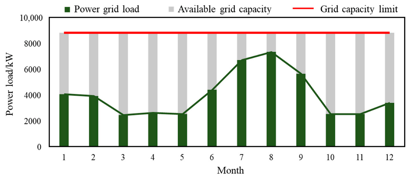
The application of electric driven HPs is restricted by the maximum power supply capacity of the grid in the researched district. Therefore, the available power supply capacity of the grid is investigated. There are five power substations around the research area and each is equipped with two transformers with a single capacity of 1100 kW, so the total power supply capacity for the research area is 11,000 kW. As required by the power company that the electrical load should not exceed 80% of the total power supply capacity, so the maximum power supply capacity of the grid is 8800 kW. The daily electrical load of the research area can be obtained through the monitored data. The available power supply capacity of the grid is shown in Figure 4.
As the maximum input power of the system is restricted by the available power of the regional grid, so the power grid constraints can be defined as:
j Π W j t P E g r i d t
where W j t is the input power of equipment j in time t, kW, Π is the device that consume electricity, P E g r i d t is the available power of the regional grid, kW.

2.3.2. Operation Optimization Model

(1)
Objective function
The objective of operation optimization model is to minimize the operation costs in the heating season, includes the energy costs of heat and electricity. It can be described as follows:
C o p = j Π k Θ j W j k × P e k + s Φ Q s × P h s  
where W j k is the input power of equipment j in time k , kW, P e k is the price of electricity in time k , CNY/kWh, Θ j is the running time of equipment j , Q s is the heat taken from the primary network in time s , kW, P h s is the price of heat in time s , CNY/kWh, Φ is the time of the system exchanges heat from the primary network.
(2)
Constraints
In addition to the constraints for design optimization model, the operation optimal process is restricted by the maximum output of equipment, which can be expressed as follows:
Q h p Q h p m a x G p u m p G p u m p m a x Φ T S m i n Φ T S Φ T S m a x
where Q h p , G p u m p and Φ T S are the heating capacity of HP, kW, flowrate of water pumps, m3/h, and heat storage of TS, GJ, respectively; Q h p m a x , G p u m p m a x , Φ T S m a x and Φ T S m i n are the output limitation of each equipment.

2.3.3. Solving Method

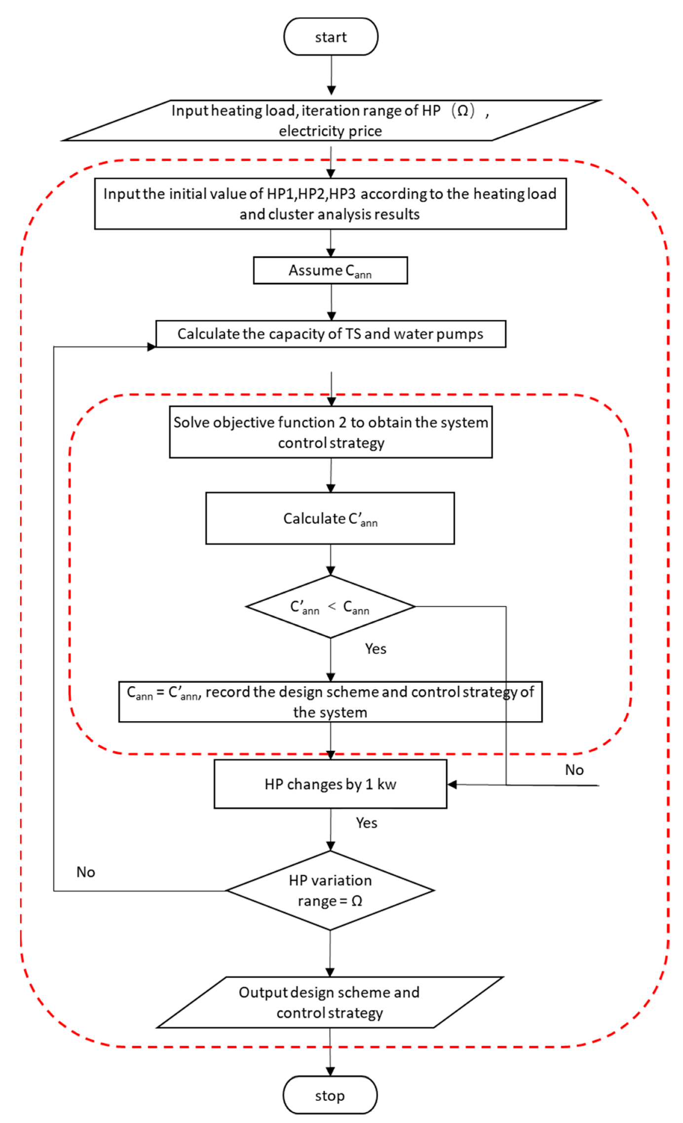
Base on the mathematical models established in the above sections, the bilevel optimization framework used in our study is shown in Figure 5, where the out layer is design optimization, and the inner layer is operation optimization. The bilevel optimization is divided into two stages [32]. Firstly, the required initial values of design optimization model are supplemented by load simulation and cluster analysis, and then the design optimization is solved through GENOPT [33]. Secondly the calculated results of the out layer are imported into the inner layer for operation optimization and thus the two stages are solved iteratively. The particle swarm optimization algorithm is used to solve the bilevel optimization model theoretically and the optimization results are then input to TRNSYS [33] software to simulate the dynamic operation performance of the system, which is given in 3.4 in detail.
In the optimization process, it is necessary to input the price of each equipment, electricity and heat to calculate the C a n n and C o p of the system, which are listed in Table 1 in detail. The prices for the purchase and installation of equipment are taken from market sales data and are converted into unit capacity prices. Electricity and heat prices are obtained from the data released by the Beijing Municipal Development and Reform Commission.

3. Case Study

A heating substation in Beijing that covers the space heating demand of a residential community is selected for the study, the research area is shown in Figure 6. The heating load is increased due to the enlargement of new building areas and the original heating substation cannot meet the heating demand. HP is considered to make up the gap of heating load in the heating substation, and ASHP as well as WSHP retrofit schemes are investigated. The basic parameters of the selected case are shown in Table 2.

3.1. The Heat-Supply Gap

The community consists of 6 buildings with identical structure. With the development of urbanization in Beijing, 6 more buildings are under construction in this community. The heating load of the community is multiplied, and the heating capacity of the original heating substation is insufficient. In order to obtain the precise heating load of the community, an energy-consumption model is built with eQUEST software using detailed field data provided by the building owner. The residential building consists of 20 floors with a total building area of 14,400 m2, so the building area of the whole community with 12 residential buildings is 172,800 m2. The buildings are heated by floor radiant heating system and the indoor temperature should be higher than 18 °C. The supply water temperature for space heating is 55 °C from the heating substation and the temperature difference between supply and return water is designed to be 10 °C. The heating period of Beijing is from 15 November to 15 March with a total of 121 days.
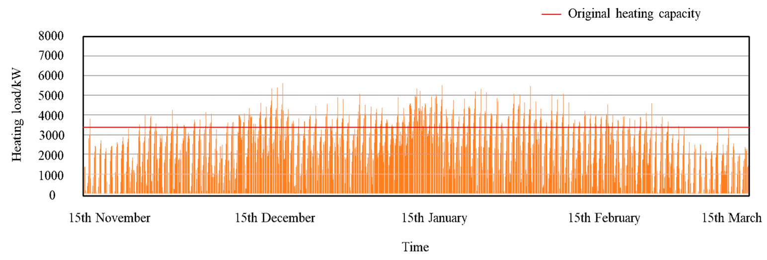
The heating load simulation results are shown in Figure 7. It can be seen from the figure that the maximum heating load is 6846 kW, which occurs at the middle of January. The heating capacity of the original heating substation is designed to be 3352 kW and the maximum heat-supply gap is 3494 kW, which should be satisfied by the HP and TS device.

3.2. Cluster Analysis

As is shown in Figure 7, the heating load of the community varies widely over time, which affects the load factor of the heat pump and, in turn, the efficiency, energy consumption, and operating costs of the system. Therefore, it is rewarding to design multiple HPs to meet the heating load than one to make the operation more flexible and ensure the HPs working at high efficiency [34]. Here, cluster analysis is carried out to divide heating load data into several categories with similar characteristics so that the heating demand in the same category can be met by one heat pump.
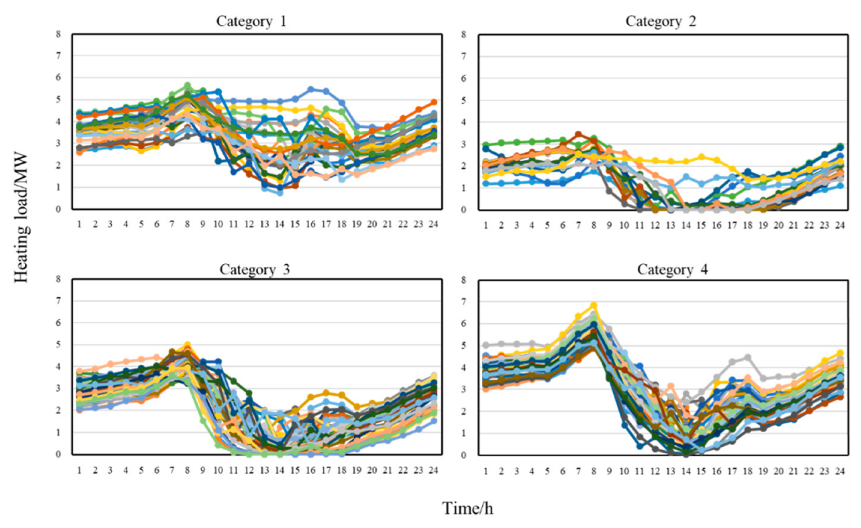
As a large database is required in cluster analysis and operation control is normally determined by the daily heating loads, the daily heating loads of the heating season are adopted as the object for clustering process and the peak value, average value and peak-valley difference are adopted as clustering variables. Considering the number of clusters should be determined using hierarchical clustering [35], SPSS 24 software [36] is used for the cluster analysis and two-step cluster algorithm is used. The two-step cluster algorithm in SPSS is applied for calculation. All variables are taken as continuous, log-likelihood is chosen for the distance measure, the number of clusters is determined automatically, and the clustering criterion is the Schwarz Bayesian criterion (BIC). Based on the above options, the number of categories calculated via two-step clustering is 4 and the results of daily heating load of each category are shown in Figure 8.
It can be seen from Figure 8 that the samples are divided into four categories and there are significant differences among different categories, which indicates that the classification is reasonable. The peak value of daily heating load for each category is 5644 kW, 3444 kW, 5011 kW and 6846 kW, and the results are then taken as the initial value and iteration range of the HP unit in the subsequent optimization model. Considering the heating load covered by the original DH network, the initial value and iteration range of the HP unit, the relevant water flow rate and TS device capacity are listed in Table 3.

3.3. TRNSYS Model

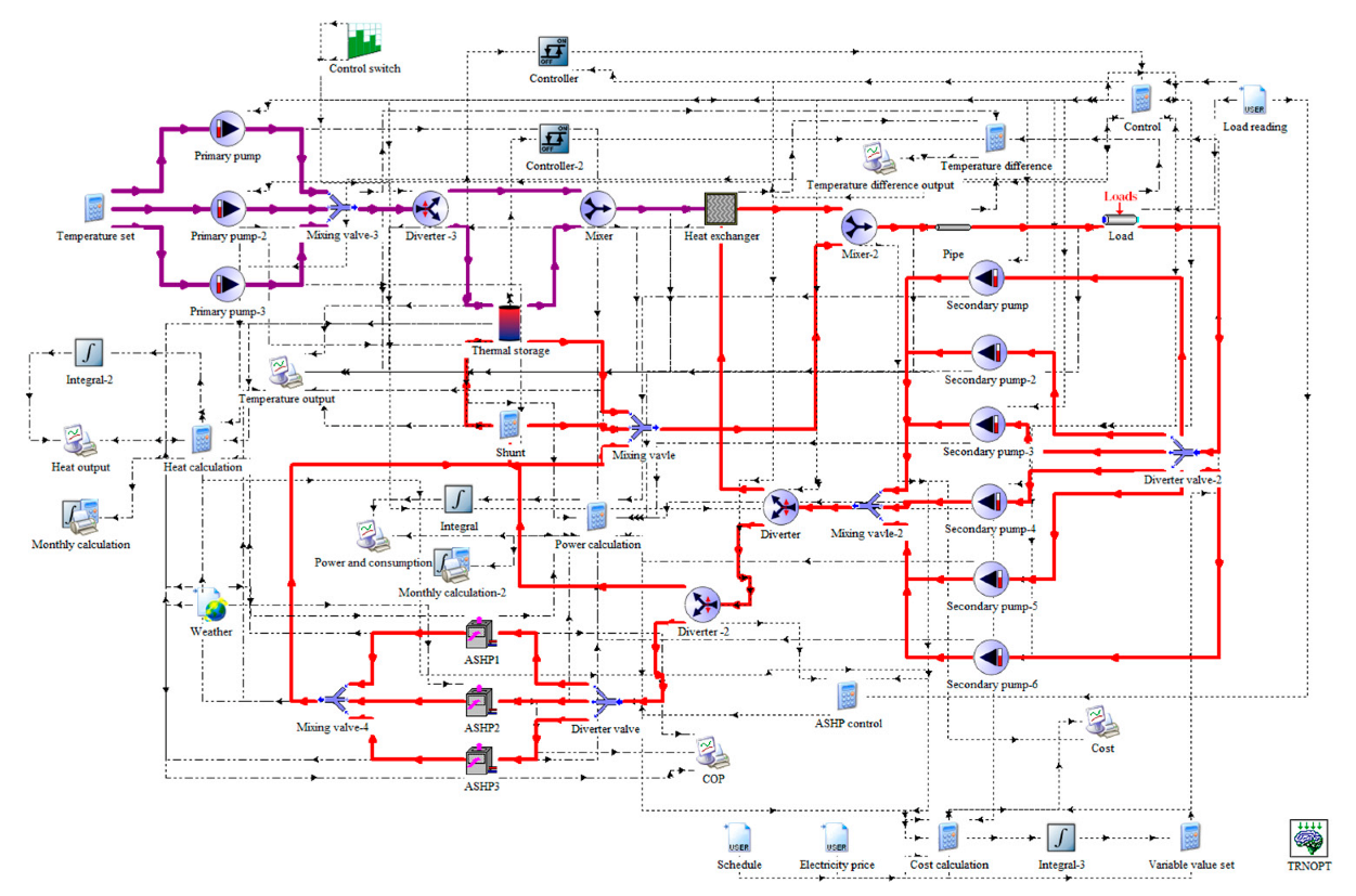
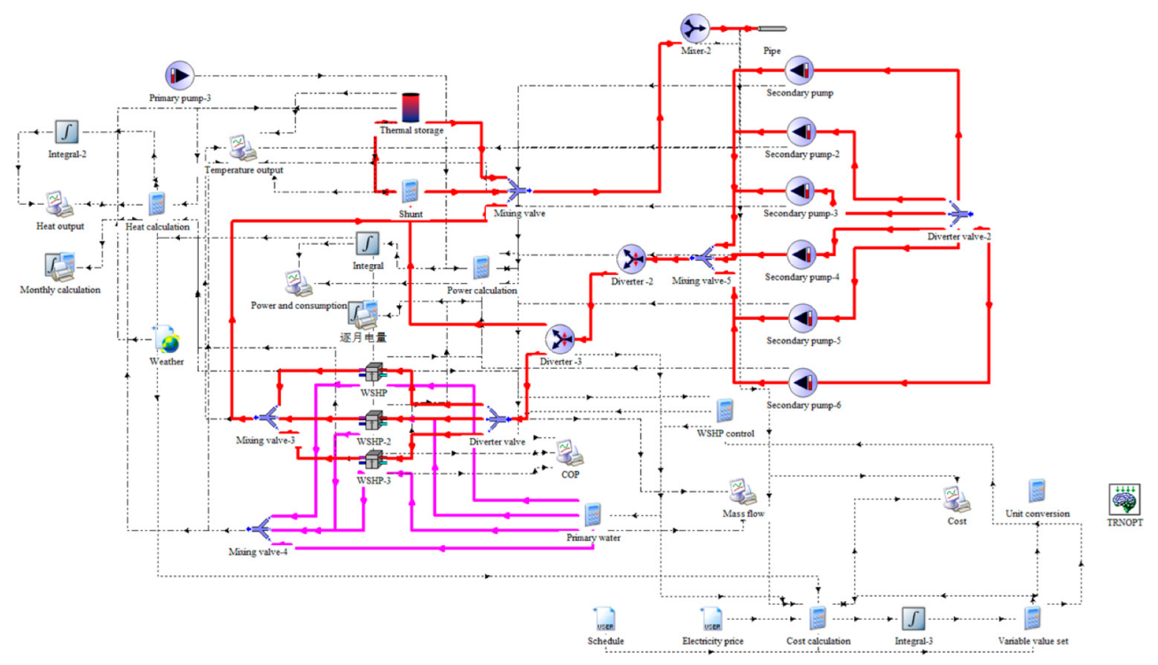
To solve the model built is 2.2, TRNSYS 16 software is used and the integrated heating systems model of ASHP with DH as well as WSHP with DH are built and solved with TRNSYS. The schematic diagrams are shown in Figure 9 and Figure 10.
The initial values of each equipment in the system are obtained according to the heating load and operating data of the research area. Table 4 illustrates the detailed initial parameters for the TRNSYS model.

3.4. Performance Indicators

3.4.1. Environmental Indicators

The annual CO2 emission of the HP combined DH system is used as the environmental indicator in this study, which can be calculated as:
CO 2 = E × F
where CO 2 represents the annual CO2 emission, E represents system’s annual energy consumption, which can be obtained by the transient simulation results. In addition, F is the carbon emission factor.

3.4.2. Economic Indicators

The net present value (NPV) over lifecycle is used to evaluate the economic performance of HP combined DH systems, which can be calculated as:
N P V = E Z C Z × 1 + r n 1 r 1 + r n I Z  
where E Z is the annual revenue of the heating substation from supplying heat to the customers, C Z is the present value of the annual operating cost, I Z is the initial investment cost of the heating substation renovation, r is the discount rate which is taken as 5% and n is the system lifetime which is taken as 20 years.

3.4.3. Grid Load Characteristics Indicators

The application of large capacity electric driven heat pumps has significant impact on the power grid of the research area, so it is necessary to analyze the characteristics of the power load and the following indicators are considered.
The peak-valley difference of the grid is to evaluate the volatility of the power load over a period, which can be calculated as:
d p v = P m a x P m i n  
where d p v is the peak-valley difference of the grid, P m a x and P m i n are the peak and valley values of the grid load, respectively.
The seasonal unbalance factor can be used as a basis for load analysis and the development of the grid’s annual operation plans, which can be calculated by the following equation:
f s = n = 1 12 P m a x , n 12 P m a x , y
where f s is the seasonal unbalance factor of the grid, P m a x , n is the peak load of month n and P m a x , y is the peak load of the year.

4. Results and Discussion

4.1. ASHP Combined DH System

The design optimization results of the ASHP combined DH system are listed in Table 5. Compared with the initial value listed in Table 3, the optimized HP capacity is reduced by about 10%. It can be attributed to the introduction of TS device and the installed capacity is not based on the peak load.
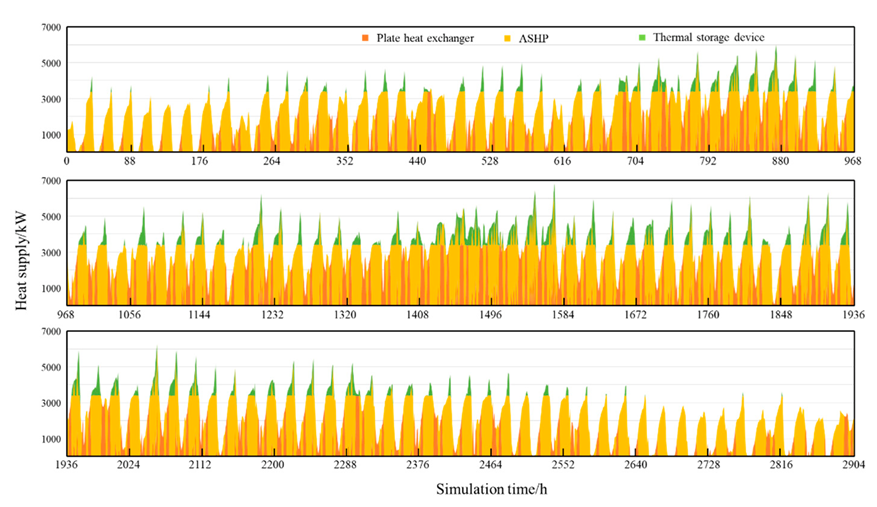
In the ASHP combined DH system, the heating load is satisfied by plate heat exchanger, heat pumps and TS device together. The operating conditions are optimized based on the operation optimization model. Figure 11 shows the hourly heat supply of each device during the entire heating season.
It can be seen from Figure 11 that the ASHP units takes most of the heating load during the heating season. It can be attributed to the lower heat price and high efficiency of ASHP, and it has high priority for space heating. The total heat supply of ASHP units in the heating season is 5.31 × 10⁶ kWh, accounting for 70.04% of the total heat supply.
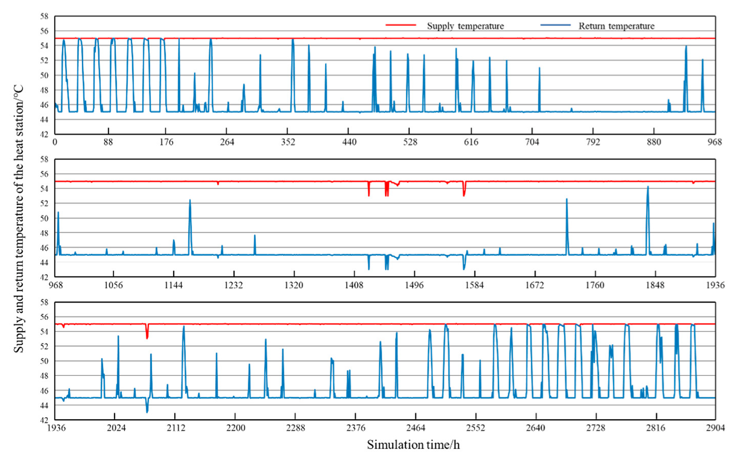
The performance and stability of the ASHP combined DH system can be evaluated by the return and supply temperature of the heating substation, as illustrated in Figure 12. It can be seen from the figure that the water supply temperature of ASHP combined DH system are stable at 55 °C. The return water temperature fluctuates with the variation of heating demand on the customer side, but are still above 43 °C. Therefore, it can conclude that the ASHP combined DH system operates stably and reliably enough to meet the community’s heating demand during the whole heating season.
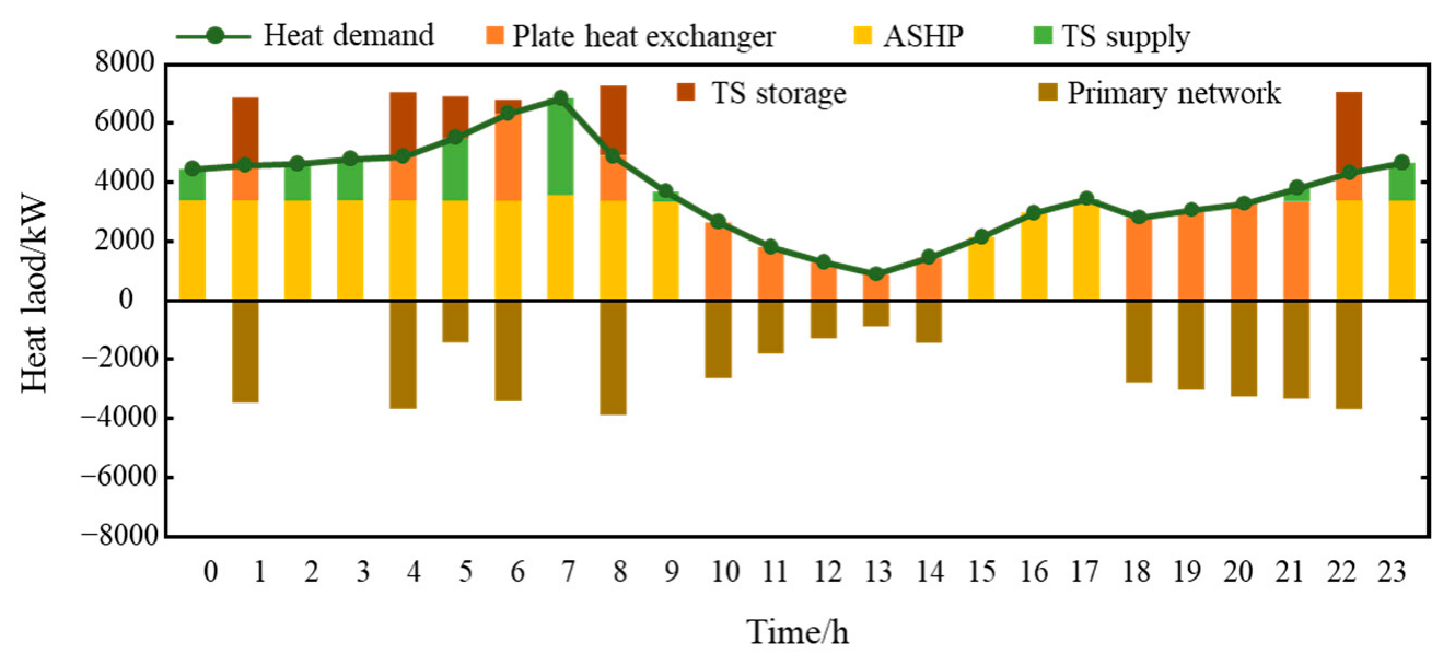
Figure 13 shows the operation results of ASHP combined DH system in a typical day. It can be found that ASHP combined DH system can make timely to response to the heating load and the flexibility of the system is improved. Figure 13 also shows the proportion of heating load for each equipment during the day. It can be seen that the ASHP nearly works at full load during the peak and plain period, the TS device and plate heat exchanger are used as auxiliary heat source during this period.

4.2. WSHP Combined DH System

The design optimization results of the WSHP combined DH system are listed in Table 6. It can be seen that the optimized HP capacity is reduced by about 8.7% and the TS device capacity increases 8.4% compared with the initial value listed in Table 3.
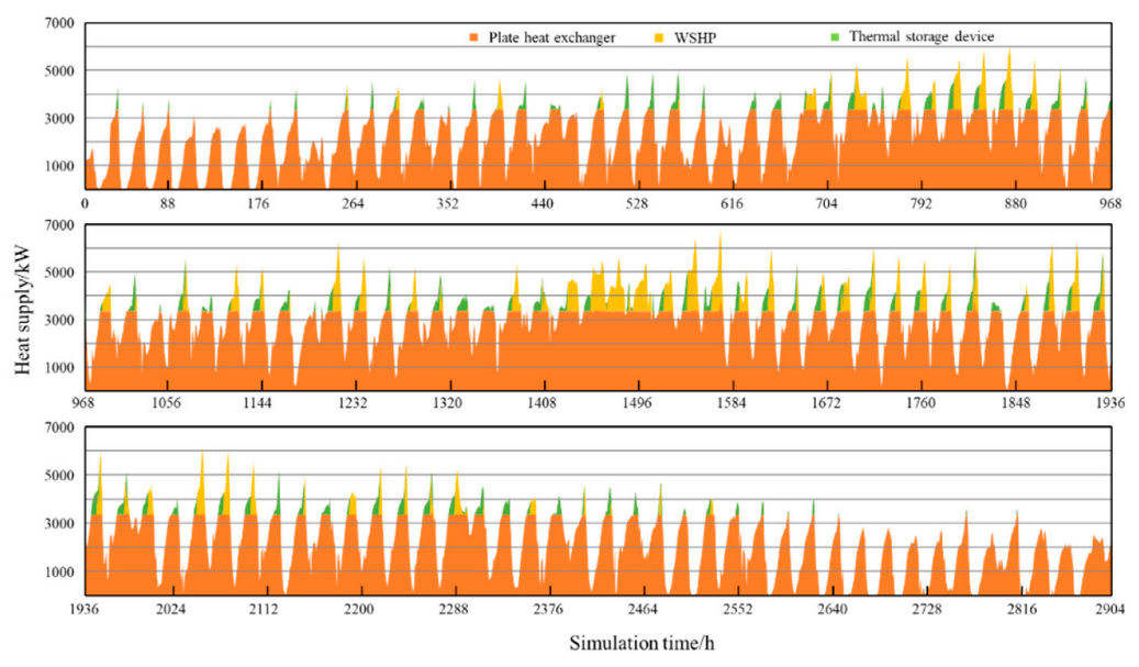
Figure 14 shows the hourly heat supply of each device in WSHP combined DH system during the entire heating season. Compared with ASHP combined DH system, plate heat exchanger takes most of the heating load in the WSHP combined DH system. It is due to the high heat price of the WSHP, which is consisted by the cost of heat from the primary network and the cost of electricity. Therefore, plate heat exchanger and TS device has higher priority than WSHP, and it is used as auxiliary heat source and operates during the peak load period.
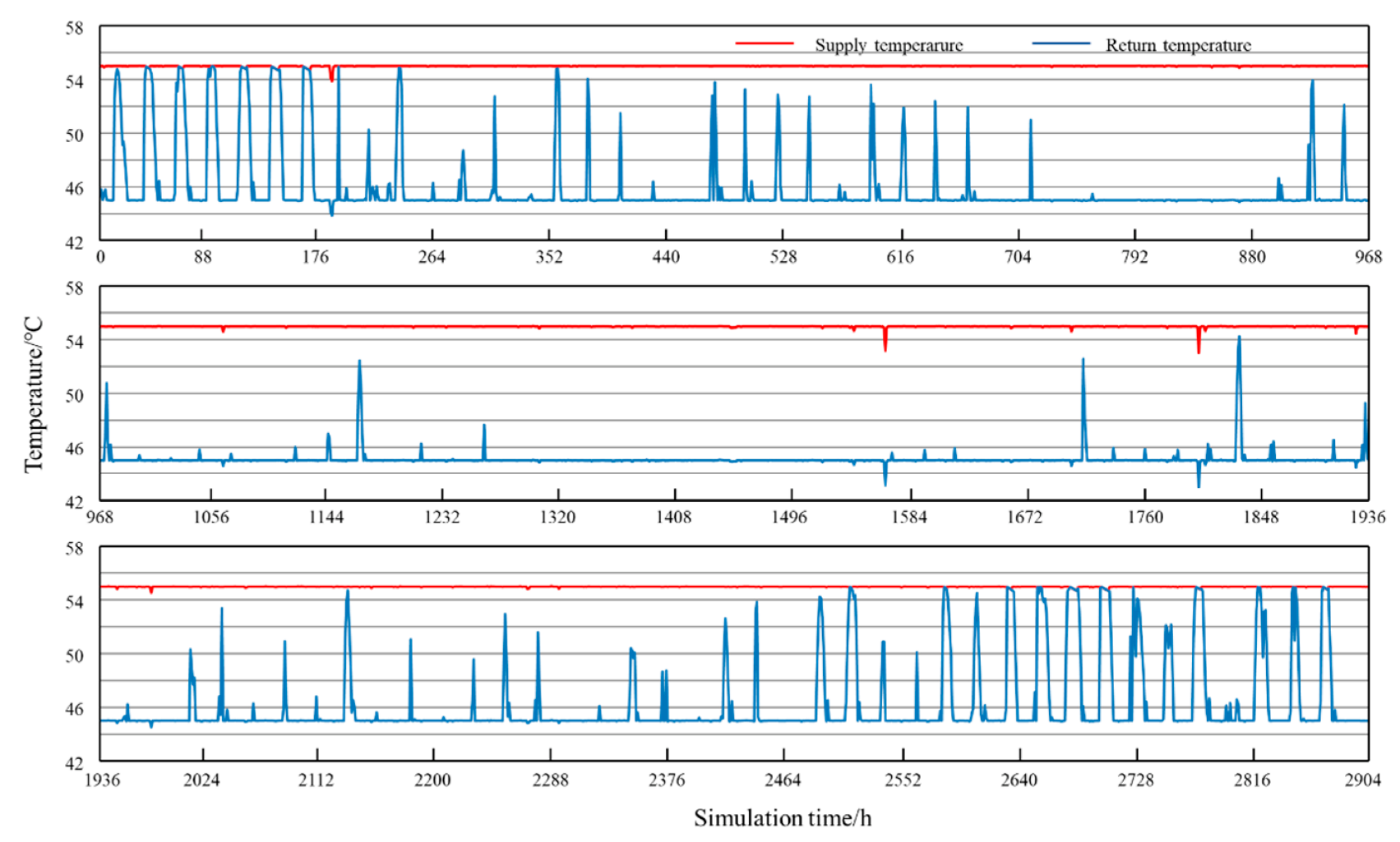
Figure 15 presents the water supply temperature of WSHP combined DH system. It can be seen from Figure 15 that the supply water temperature drops slightly at some points during the heating period, but are still above 53 °C. The return water temperature fluctuates with the variation of heating demand on the customer side and remain above 45 °C. Therefore, it can conclude that WSHP combined DH system operates stably and reliably enough to meet the community’s heating demand during the whole heating season.
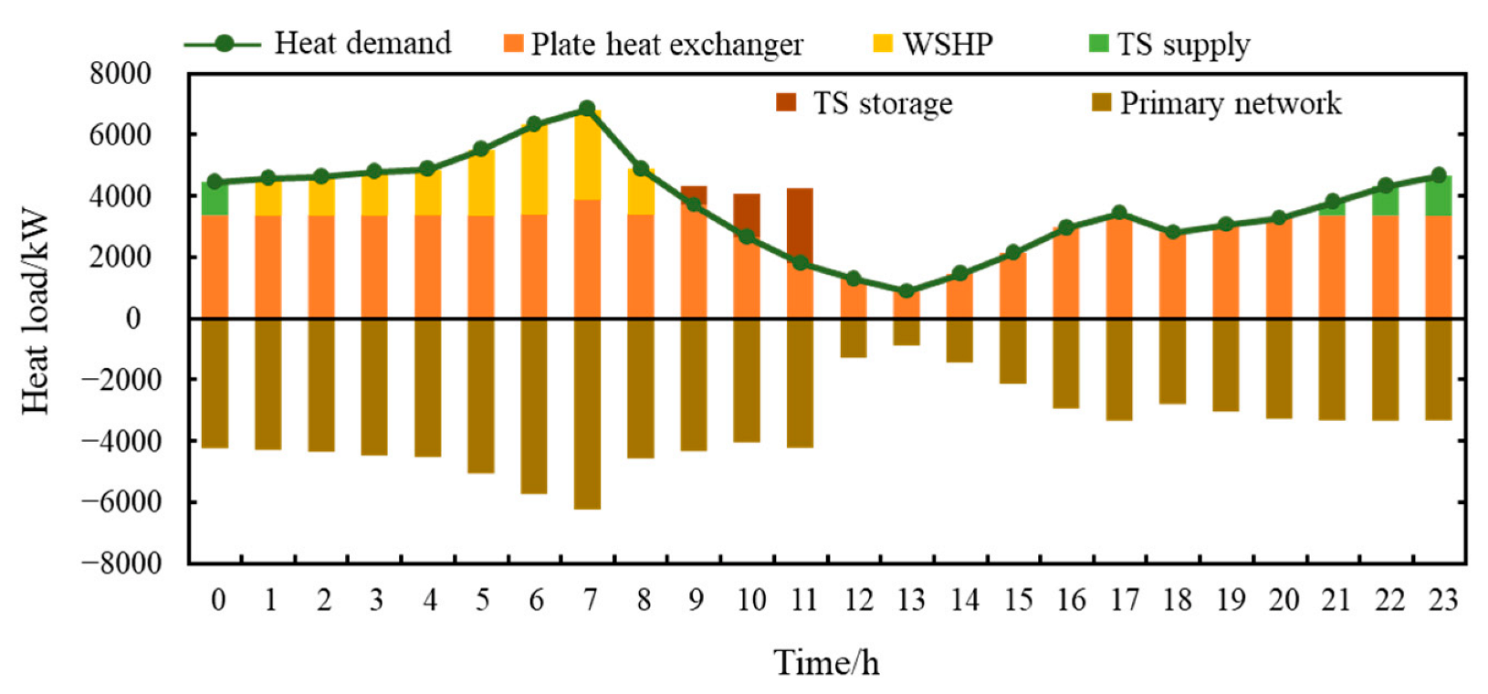
Figure 16 shows the operation results of WSHP combined DH system in a typical day. It can be found that although the control strategies of WSHP combined DH system are quite different from ASHP combined DH system, the flexibility of WSHP combined DH system is still improved. The operation of WSHP combined DH system is much similarly to the conventional heating substation with only plate heat exchangers, but control strategies are optimized to reach the lowest expense. The WSHP and TS device work at the peak load period to ease the burden of the primary network.

4.3. Performance Analysis

4.3.1. Annual Energy Consumption

From Table 7, it can be seen that the annual energy consumption of ASHP combined DH system is the lowest due to the high efficiency and the free energy gain from the air. The energy consumption of WSHP combined DH system is basically the same with the conventional system. However, the introduction of WSHP is able to meet the growing heat demand without constructing additional heating substations and enlarging the networks. The results also indicate that the ASHP combined DH system achieves the best CO2 mitigation potential, and it reduces the CO2 emission by about 10.8% compared with the conventional system. However, the CO2 mitigation potential of WSHP combined DH system is the lowest, it can be attributed to the higher carbon emission factor of electricity than that of the natural gas.

4.3.2. Economic Performance

The economic performances of ASHP and WSHP combined DH system are listed in Table 8. The results indicate that the initial cost of ASHP is higher than that of WSHP, but the operation costs are 33% lower. This is consistent with the results presented in Table 7, wherein ASHP system has the lowest annual energy consumption. The NPV of ASHP combined DH system is about 117.35% higher than that of the WSHP combined DH system, so it has better economic performance. Therefore, the ASHP combined DH system is the preferred solution for the heating substation retrofit.

4.3.3. Impacts on Power Grid

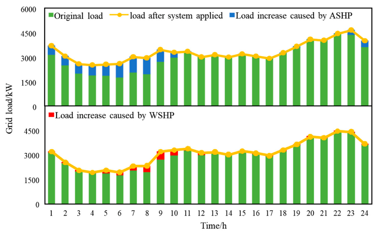
The impacts of introducing ASHP and WSHP into the heating substation on the regional power grid are considered in this study. Figure 17 illustrates the daily impacts and it can be seen from Figure 17 that the hourly grid load with ASHP operation increases significantly during the plain and valley load tariff periods of 23:00–10:00. During the peak load tariff period, the operating scheme of ASHP combined DH system is adjusted and plate heat exchanger is preferred, while ASHPs are activated only during peak heating load and works at low load factor, corresponding to 18:00–21:00. The peak-valley difference of power grid in a day is reduced by about 20% due to the application of ASHP. It has significant effects on peak shaving and improves the utilization efficiency of the power grid. The application of WSHP combined DH system also improves the hourly grid load. However, the increase is much lower than that of ASHP combined DH system. It can be attributed to the totally different control strategy of WSHP combined DH system, which initiates WSHPs only during peak heating load as auxiliary heating device. In addition, the peak-valley difference of power grid in a day is reduced by about 5.6% due to the application of WSHP.
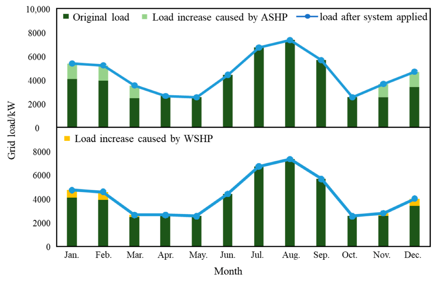
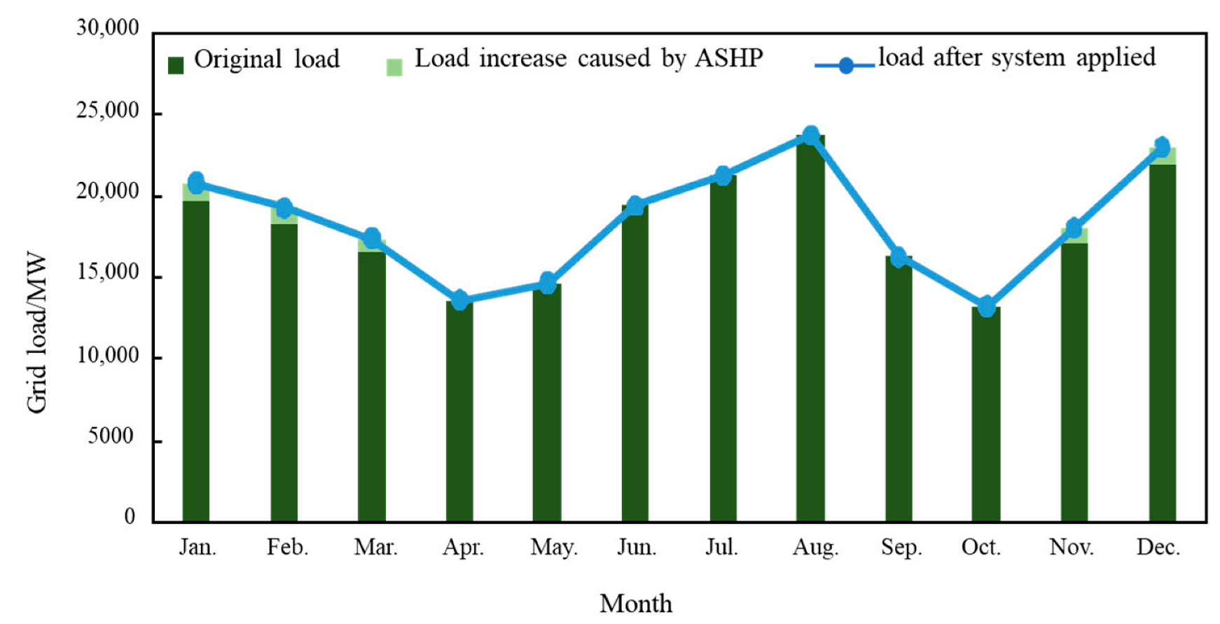
The electrical load distribution of the researched area throughout the year is also improved, as shown in Figure 18. The peak load period appears in July and August due to the high air-conditioning load, and the seasonal unbalance factor is only 0.542 for this region. The introduction of ASHP and WSHP increases the regional power load in heating season. The seasonal unbalance factor is increased by 13.4% to 0.615 with the application of ASHP combined DH system, and it is increased by 4.9% to 0.574 by introducing WSHP into DH system, which can improve the utilization efficiency and smooth the seasonal power fluctuation of the regional power grid, as well as enhance the flexible interaction between power grid and heating network.

4.4. Potential Analysis of ASHP Combined DH System

As released by the 14th five-year plan in district heating development that the urban heating area in Beijing will reach 1.05 billion m2 by 2025 and the clean heating area will take about 10%. Furthermore, the traditional natural gas heating is forbidden, and the increased heating load should be satisfied by the clean heating technologies. As the increase of heating load during these years, it will come to 44,100 MW by 2025 and a heating power deficit of 2930 MW will be a difficult problem for the government to solve. ASHP combined with DH will be a competitive technology to fill the heating gap and avoid the reconstruction of heating substations and networks, as well as increase the clean heating proportion to realize carbon mitigation in DH system. Thus, the economic and environmental benefits of large-scale application of ASHP combined DH system is evaluated.
The 2025 scenario is studied by assuming that the additional 2930 MW of heating load is taken by the ASHP combined DH system through heating substations. The results in the previous section are taken as the basis for analysis here. The potential of the large-scale application of ASHP combined DH systems in Beijing are analyzed and compared with the traditional natural gas heating system in terms of carbon mitigation, energy saving and economic benefits.
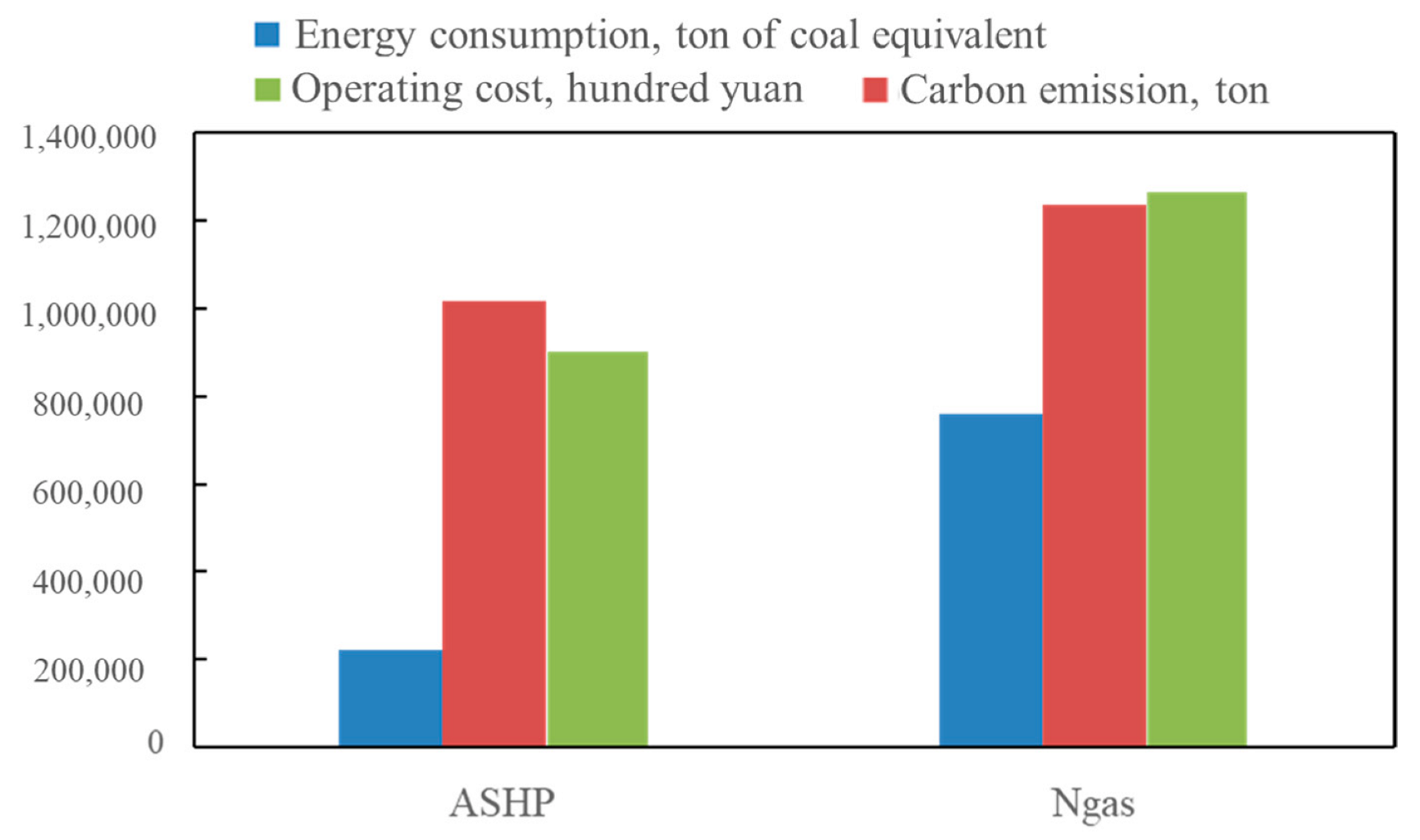
It can be found from Figure 19 that the energy saving potential of ASHP combined DH system in 2025 is about 539,000 tce/year (ton of coal equivalent/year), and the natural gas shortage in Beijing can be alleviated. Compared to the traditional natural gas heating system, the large-scale application of ASHP system in 2025 will reduce CO2 emission by 219,000 ton/year, which is of great significance to achieve carbon neutrality target. As discussed in the previous section that the ASHP combined DH system is economically feasible. The large-scale application will bring economic benefits of 362 million CNY/year and the investment payback period is less than 2 years. Therefore, the proposed district heating system can be widely promoted. It can accelerate the realization of low-carbon heating as well as the transition to the 4th GDH.
Figure 20 shows the electrical load distribution of Beijing with the large-scale application of ASHP combined DH system. It can be found that the current peak load period appears in August and the current grid capacity is sufficient to accommodate the increase in power load due to the introduction of ASHP. The large-scale application of ASHP combined DH system brings a slight increase in grid load in heating season and improves the seasonal unbalance factor by 2.3% to 0.775. Furthermore, the ASHP combined DH system has high flexible potential in coupling the power grid and DH system.

5. Conclusions

In this study, a DH system retrofit scheme based on electric driven heat pump to solve the heating power shortage problem is developed. Two retrofit configurations based on ASHP and WSHP, respectively, are proposed and a bilevel optimization model for the system is developed. Models of these two retrofit schemes are built and solved by TRNSYS to evaluate the system’s performance. In addition, a scenario in 2025 is investigated to evaluate the potential of large-scale application of the retrofit scheme in Beijing. The main conclusions are drawn as follows:
(1)
The proposed heat pump combined district heating systems are proved to be a feasible way to enlarge the heating capacity without reconstruction of heating substations and networks. Both systems could work stable enough to meet the increasing heating load and achieve considerable annual revenue.
(2)
Taking the selected case as example, the ASHP combined system could cut down the annual operation cost by about 33% and improve the NPV over lifecycle by about 117% in comparison with the WSHP combined DH system.
(3)
Compared with enlarging the capacity of plate heat exchanger retrofit scheme, the ASHP combine DH system with optimal system configuration has better thermal and environmental performance. It can reduce the energy consumption and CO2 emission by49% and 10.8%, respectively.
(4)
The introduction of ASHP and WSHP to heating substation can reduce the peak-valley difference of the regional power grid in a typical day by 20% and 5.6%, respectively. In addition, the seasonal unbalance factor by introducing ASHP is increased by 13.4% while that for WSHP is increased by 4.9%. Both systems have significant effects on peak shaving and improves the utilization efficiency of the power grid.
(5)
The large-scale application of ASHP combined DH system in Beijing can bring significant economic and environmental benefits. It can save 539,000 tce energy consumption, reduce 219,000 ton carbon emissions and bring 362 million CNY profits in the year of 2025.

Author Contributions

Data curation, S.X.; Investigation, S.L. and Y.L.; Methodology, H.Z.; Resources, S.Z. and Z.L.; Supervision, B.L.; Writing—original draft, L.C.; Writing—review & editing, Z.Y. and W.Z. All authors have read and agreed to the published version of the manuscript.

Funding

This research was funded by the Science and technology project of state grid corporation-research and demonstration of municipal heating technology for power grid-heat network coupling (5400-202111161A-0-0-00).

Data Availability Statement

Not applicable.

Conflicts of Interest

The authors declare no conflict of interest.

Abbreviations

4th GDHfourth generation district heating
AHPabsorption heat pump
ASHPair source heat pump
CHPcombined heat and power
CNYChinese yuan
COPcoefficient of performance
DHdistrict heating
HPheat pump
NPVnet present value
PSOparticle swarm optimization
SCOPseasonal coefficient of performance
TSthermal storage
WPwater pump
WSHPwater source heat pump

References

  1. The State Council of China. 2021. Available online: http://www.gov.cn/zhengce/2021-10/24/content_5644613.htm (accessed on 2 September 2022). (In Chinese)
  2. Building Energy Research Center of Tsinghua University. Annual Report of China Building Energy Conservation 2019; China’s Architecture and Building Press: Beijing, China, 2019. (In Chinese) [Google Scholar]
  3. Fu, L.; Li, Y.; Wu, Y. Low carbon district heating in China in 2025-a district heating mode with low grade waste heat as heat source. Energy 2021, 230, 120765. [Google Scholar] [CrossRef]
  4. The State Council of China. 2018. Available online: http://www.gov.cn/xinwen/2018-02/04/content_5263760.htm (accessed on 2 September 2022). (In Chinese)
  5. Lund, H.; Werner, S.; Wiltshire, R. 4th Generation District Heating (4GDH): Integrating smart thermal grids into future sustainable energy systems. Energy 2014, 68, 1–11. [Google Scholar] [CrossRef]
  6. Lund, H.; Østergaard, P.A.; Chang, M. The status of 4th generation district heating: Research and results. Energy 2018, 164, 147–159. [Google Scholar] [CrossRef]
  7. Lund, H.; Duic, N.; Østergaard, P.A. Future district heating systems and technologies: On the role of smart energy systems and 4th generation district heating. Energy 2018, 165, 614–619. [Google Scholar] [CrossRef]
  8. Jodeiri, A.M.; Goldsworthy, M.J.; Buffa, S.; Cozzini, M. Role of sustainable heat sources in transition towards fourth generation district heating–A review. Renew. Sustain. Energy Rev. 2022, 158, 112156. [Google Scholar] [CrossRef]
  9. Ziemele, J.; Gravelsins, A.; Blumberga, A. Combining energy efficiency at source and at consumer to reach 4th generation district heating: Economic and system dynamics analysis. Energy 2017, 137, 595–606. [Google Scholar] [CrossRef]
  10. Ziemele, J.; Gravelsins, A.; Blumberga, A. System dynamics model analysis of pathway to 4th generation district heating in Latvia. Energy 2016, 110, 85–94. [Google Scholar] [CrossRef]
  11. Averfalk, H.; Werner, S. Economic benefits of fourth generation district heating. Energy 2020, 193, 116727. [Google Scholar] [CrossRef]
  12. Lund, H.; Thorsen, J.E.; Jensen, S.S.; Madsen, F.P. Fourth-Generation District Heating and Motivation Tariffs. ASME Open J. Eng. 2022, 1, 8. [Google Scholar] [CrossRef]
  13. Li, H.; Nord, N. Transition to the 4th generation district heating-possibilities, bottlenecks, and challenges. Energy Proc. 2018, 149, 483–498. [Google Scholar] [CrossRef]
  14. Su, C.; Urban, F. Carbon Neutral China by 2060: The Role of Clean Heating Systems. Energies 2021, 14, 7461. [Google Scholar] [CrossRef]
  15. Bach, B.; Werling, J.; Ommen, T. Integration of large-scale heat pumps in the district heating systems of Greater Copenhagen. Energy 2016, 107, 321–334. [Google Scholar] [CrossRef] [Green Version]
  16. Lund, R.; Ilic, D.; Trygg, L. Socioeconomic potential for introducing large-scale heat pumps in district heating in Denmark. J. Clean. Prod. 2016, 139, 219–229. [Google Scholar] [CrossRef] [Green Version]
  17. Zhang, X.; Strbac, G.; Teng, F. Economic assessment of alternative heat decarbonisation strategies through coordinated operation with electricity system–UK case study. Appl. Energy 2018, 222, 79–91. [Google Scholar] [CrossRef]
  18. Pinson, P.; Mitridati, L.; Ordoudis, C. Towards fully renewable energy systems: Experience and trends in Denmark. CSEE J. Power Energy Syst. 2017, 3, 26–35. [Google Scholar] [CrossRef]
  19. Zhao, N.; You, F. Can renewable generation, energy storage and energy efficient technologies enable carbon neutral energy transition? Appl. Energy 2020, 279, 115889. [Google Scholar] [CrossRef]
  20. Sun, F.; Xie, Y.; Svendsen, S. New low-temperature central heating system integrated with industrial exhausted heat using distributed electric compression heat pumps for higher energy efficiency. Energies 2020, 13, 6582. [Google Scholar] [CrossRef]
  21. Blarke, M.B.; Lund, H. Large-scale heat pumps in sustainable energy systems: System and project perspectives. Sustain. Develop. Energy Water Environ. Syst. 2007, 69–78. [Google Scholar] [CrossRef] [Green Version]
  22. Meibom, P.; Kiviluoma, J.; Barth, R. Value of electric heat boilers and heat pumps for wind power integration. Wind Energy 2007, 10, 321–337. [Google Scholar] [CrossRef]
  23. Kiviluoma, J.; Meibom, P. Flexibility from district heating to decrease wind power integration costs. In Proceedings of the 12th International Symposium on District Heating and Cooling, Tallinn, Estonia, 5–7 September 2010; pp. 5–7. [Google Scholar]
  24. Münster, M.; Morthorst, P.E.; Larsen, H.V. The role of district heating in the future Danish energy system. Energy 2012, 48, 47–55. [Google Scholar] [CrossRef]
  25. Mathiesen, B.V.; Blarke, M.; Hansen, K. The Role of Large-Scale Heat Pumps for Short Term Integration of Renewable Energy; Aalborg University: Aalborg, Denmark, 2011. [Google Scholar]
  26. Song, Z.; Wang, N.; You, S. Integration of geothermal water into secondary network by absorption-heat-pump-assisted district heating substations. Energy Build. 2019, 202, 109403. [Google Scholar] [CrossRef]
  27. Lofberg, J. YALMIP: A toolbox for modeling and optimization in MATLAB. In Proceedings of the IEEE International Symposium on Computer Aided Control Systems Design, Taipei, Taiwan, 2–4 September 2005; IEEE: Piscataway, NJ, USA, 2005. [Google Scholar]
  28. Shu, H.; Duanmu, L.; Shi, J. Field measurement and energy efficiency enhancement potential of a seawater source heat pump district heating system. Energy Build. 2015, 105, 352–357. [Google Scholar] [CrossRef]
  29. Colson, B.; Marcotte, P.; Savard, G. An overview of bilevel optimization. Ann. Oper. Res. 2007, 153, 235–256. [Google Scholar] [CrossRef]
  30. Li, X.; Tian, P.; Min, X. A hierarchical particle swarm optimization for solving bilevel programming problems. In Proceedings of the International Conference on Artificial Intelligence and Soft Computing, Zakopane, Poland, 25–29 June 2006; Springer: Berlin/Heidelberg, Germany, 2006. [Google Scholar]
  31. Yubo, B.H. Reliability research of building energy-consumption analysis by DOE-2 software. Heati. Vent. Air Cond. 2003, 33, 90–92. [Google Scholar]
  32. Sinha, A.; Malo, P.; Deb, K. A Review on Bilevel Optimization: From Classical to Evolutionary Approaches and Applications. IEEE Trans. Evolut. Comput. 2018, 22, 276–295. [Google Scholar] [CrossRef]
  33. Asadi, E.; da Silva, M.G.; Antunes, C.H.; Dias, L. A multi-objective optimization model for building retrofit strategies using TRNSYS simulations, GenOpt and MATLAB. Build. Environ. 2012, 56, 370–378. [Google Scholar] [CrossRef]
  34. Guo, F.; Li, Y.; Xu, Z.; Qin, J.; Long, L. Multi-objective optimization of multi-energy heating systems based on solar, natural gas, and air- energy. Sustain. Energy Technol. Assess. 2021, 47, 101394. [Google Scholar] [CrossRef]
  35. D’Andrade, R.G. hierarchical clustering. Psychometrika 1978, 43, 59–67. [Google Scholar] [CrossRef]
  36. Pallant, J. SPSS Survival Manual: A Step by Step Guide to Data Analysis Using SPSS for Windows Version 15; SPSS Survival Manual: A Step by Step Guide to Data Analysis Using SPSS for Windows Version 15; Routledge: London, UK, 2007. [Google Scholar]
Figure 1. Schematic diagram of ASHP combined DH system.
Energies 15 07622 g001
Figure 2. Schematic diagram of WSHP combined DH system.
Energies 15 07622 g002
Figure 3. The schematic diagram of flow mixer.
Energies 15 07622 g003
Figure 4. Power grid constraints of the research area.
Energies 15 07622 g004
Figure 5. The flowchart of the bilevel optimization.
Energies 15 07622 g005
Figure 6. The satellite map of the research area.
Energies 15 07622 g006
Figure 7. Heating load of the community during heating period.
Energies 15 07622 g007
Figure 8. Cluster analysis results of daily heating load.
Energies 15 07622 g008
Figure 9. TRNSYS model of ASHP combined with DH system.
Energies 15 07622 g009
Figure 10. TRNSYS model of WSHP combined with DH system.
Energies 15 07622 g010
Figure 11. Hourly results of ASHP combined DH system during the heating season.
Energies 15 07622 g011
Figure 12. Supply and return temperature of ASHP combined DH system.
Energies 15 07622 g012
Figure 13. Hourly results of ASHP combined DH system on a typical day.
Energies 15 07622 g013
Figure 14. Hourly results of WSHP combined DH system during the heating season.
Energies 15 07622 g014
Figure 15. Supply and return temperature of WSHP combined DH system.
Energies 15 07622 g015
Figure 16. Hourly results of WSHP combined DH system on a typical day.
Energies 15 07622 g016
Figure 17. Impacts of ASHP on regional power grid in a typical day.
Energies 15 07622 g017
Figure 18. Distribution of power grid load over a year.
Energies 15 07622 g018
Figure 19. Large-scale application performance of ASHP combined DH system in Beijing.
Energies 15 07622 g019
Figure 20. Large-scale application impacts of ASHP combined DH system on power grid.
Energies 15 07622 g020
Table 1. Parameters for Life-cycle cost.
ItemClassificationValue
Equipment costASHP550 CNY/kW
WSHP450 CNY/kW
Water pump140 CNY/(m3/h)
TS5000 CNY/GJ
Installation cost2.5% of equipment price
Electricity chargesPeak load price1.293 CNY/kWh
Plain load price0.7673 CNY/kWh
Valley load price0.2939 CNY/kWh
Municipal heating chargesUnit heat price86.5 CNY/GJ
Note: Peak load price period 10:00~15:00, 18:00~21:00; Plain load price period 7:00~10:00, 15:00~18:00; Valley load price period 23:00~7:00.
Table 2. Case study parameters.
ItemValue
Current heating area86,400 m2
Building area under construction86,400 m2
Total heating area172,800 m2
Heating period121 days
Current heating capacity3352 kW
Supply temperature of DH substation55 °C
Return temperature of DH substation45 °C
Supply temperature of primary network110 °C
Power grid capacity limit8800 kW
Table 3. Initial values and iteration ranges of the variables.
VariableInitial ValueInterion Range
Rated capacity of HP1650 kW200~1100 kW
Rated capacity of HP21200 kW600~1800 kW
Rated capacity of HP31600 kW1000~2200 kW
Rated flow rate of WP156 m3/h50~200 m3/h
Rated flow rate of WP2103 m3/h50~200 m3/h
Rated flow rate of WP3136 m3/h50~200 m3/h
TS device capacity30 GJ0~100 GJ
Table 4. Initial parameters for the simulation model.
ItemParameterValue
Primary networkSupply temperature110 °C
Plate heat exchangerHeat transfer capacity3352 kW
Heat transfer coefficient3 kW/(m2·°C)
Heat transfer area20.40 m2
Output temperature50 °C
Primary pumpNumber3
Rated flow16 m3/h
Lift35 m
Efficiency0.70
Rated power2.18 kW
Frequency30~50 Hz
Secondary pump (original)Number3
Rated flow98 m3/h
Lift35 m
Efficiency0.70
Rated power13.36 kW
Frequency30~50 Hz
Heat pumpNumber3
Power range20~100% of rated power
Secondary pump (new)Number3
Efficiency0.70
Frequency30~50 Hz
Thermal storageUpper temperature limit90 °C
Lower temperature limit55 °C
DH design parametersHeat load6846 kW
Supply temperature55 °C
Return temperature45 °C
Table 5. Optimization results of ASHP combined DH system.
ItemOptimal Value
Rated capacity of HP11150 kW
Rated capacity of HP2700 kW
Rated capacity of HP31250 kW
Rated flow rate of WP1115 m3/h
Rated flow rate of WP285 m3/h
Rated flow rate of WP394 m3/h
TS device capacity25.16 GJ
Table 6. Optimization results of WSHP combined DH system.
ItemOptimal Value
Rated capacity of HP11100 kW
Rated capacity of HP2850 kW
Rated capacity of HP31200 kW
Rated flow rate of WP194 m3/h
Rated flow rate of WP298 m3/h
Rated flow rate of WP3102 m3/h
TS device capacity32.52 GJ
Table 7. Comparison of annual energy consumption.
ASHPWSHPConventional
Electricity/kWhCirculating pumps6.93 × 1047.67 × 1047.49 × 104
Heat pump unit1.57 × 1069.32 × 104
Heat/kWhPlate heat exchanger1.73 × 1066.84 × 1067.58 × 106
Thermal storage5.52 × 1052.85 × 105
Heat pump unit 3.67 × 10⁵
Carbon emission/ton 1383.11595.91562.3
Table 8. Economic indicators of ASHP and WSHP combined DH system.
SystemInitial
Investment/CNY
Annual
Operation Costs/CNY
Annual Revenue from Heat Sales Based on Area Charges/CNYAnnual Revenue from Heat Sales Based on Heat Charges/CNYNPV by Area Charge/CNYNPV by Heat Charge/CNY
ASHP2,131,3001,665,2004,147,2003,288,10028,799,30018,093,500
WSHP1,708,7002,483,0004,147,2003,288,10019,030,5008,324,600
Publisher’s Note: MDPI stays neutral with regard to jurisdictional claims in published maps and institutional affiliations.