Article

Design and Fabrication of a Robust Chitosan/Polyvinyl Alcohol-Based Humidity Sensor energized by a Piezoelectric Generator

1
Department of Electronic Engineering, Gachon University, 1342 Seongnamdaero, Seongnam-si 13120, Korea
2
Department of Electrical Engineering, Sukkur IBA University, Sukkur 65200, Pakistan
3
Department of Health Science and Technology, GAIHST, Gachon University, Incheon 21999, Korea
*
Author to whom correspondence should be addressed.
Energies 2022, 15(20), 7609; https://doi.org/10.3390/en15207609
Submission received: 14 September 2022 / Revised: 11 October 2022 / Accepted: 12 October 2022 / Published: 15 October 2022

Abstract

:
Due to their rapid growth in industrial and environmental applications, there is a need to develop self-powered humidity sensor systems with improved sensitivity, a wide detection range, and an eco-friendly nature. In this study, an aqueous solution of chitosan (CS) and polyvinyl alcohol (PVA) was blended to yield a composite film material with enhanced humidity detection properties. Meanwhile, a polyvinylidene difluoride (PVDF)-loaded chitosan composite film was developed and employed as a piezoelectric generator. Moreover, the developed composite materials for both devices (the piezoelectric generator and the humidity sensor) were optimized based on output performance. The piezoelectric generator generates a maximum of 16.2 V when a force of 10 N is applied and works as a power source for the humidity-sensing film. The sensing film swells in response to changes in relative humidity, which affects film resistance. This change in resistance causes a change in voltage through the piezoelectric generator and allows the precise measurement of relative humidity (RH). The fabricated sensor showed a linear response (R2 = 0.981) with a reasonable sensitivity (0.23 V/% RH) in an environment with an RH range of 21–89%. In addition, the device requires no external power, and therefore, it has numerous sensing applications in various fields.

Graphical Abstract

1. Introduction

There are myriad environmental parameters, such as light, pressure, temperature and humidity, that have a significant importance in different applications. Of these, humidity plays a pivotal role, especially in medical, agricultural, food, and other industrial applications. Controlling and monitoring humidity has been attracting increasing interest in various fields, including pharmaceutical processing, food storage, medicine processing, and weather forecasting [1,2,3,4]. The humidity-sensing mechanism is based on changes in the electrical properties of the sensing film in response to water molecules. The change due to water adsorption can be resistive [5], capacitive [6], optical [7], impeditive [8], or acoustic [9]. Generally, humidity sensors are characterized by various essential parameters, including high sensitivity, quick response time, wide detection range, low fabrication cost, simple fabrication methodology, and linearity. A wide range of materials, techniques, and mechanisms have been investigated with respect to their humidity-sensing capabilities. Active sensing layers may include polymers [10], ceramics [11], metal oxides [12], and carbon nanotubes [13,14]. Recently, 2D materials with excellent sensing properties have also been explored for humidity-sensing applications [15,16].
Different functional materials have been proposed for sensing humidity in the environment. For instance, polymer moisture sensors exhibit excellent sensing qualities. In addition, polymeric sensors possess the advantages of simple fabrication, light weight, and low cost [17,18]. Similarly, chitosan, a biocompatible polymer, is considered an ideal humidity-sensing material that can interact with water molecules via hydrogen bonding. Chitosan is a polysaccharide composed of B-(1,4)-linked D-glucosamine residues with a varying number of randomly positioned N-acetyl-glucosamine groups, depending on the mode of preparation [19,20]. It has two types of reactive functional groups: an amino group and a hydroxyl group [21]. Chitosan-based devices have been widely investigated in nanoelectronics as humidity and gas sensors, because they are biocompatible and naturally biodegradable [22,23]. In addition, they have excellent film-forming properties and the ability to swell when exposed to water molecules [24,25]. This change in the physical structure of chitosan affects both its absorption spectrum and electrical conductivity, which ensures its application as a sensor of relative humidity. Moreover, PVA is a non-toxic and inexpensive hydrophilic semicrystalline polymer with strong film-forming properties. It can boost the humidity-sensing effectiveness of chitosan owing to the additional water adsorption sites. Although an enormous amount of research has been performed on the development of cost-effective and inexpensive materials for robust sensing, most of these sensors rely on external power sources, which limits their application in the case of power failure. Simultaneously, conventional batteries fail to address permanent energy demands because of their heavy weight, limited life span, and potential to cause environmental damage. Therefore, these shortcomings necessitate the establishment of highly desirable self-powered humidity sensors that combine humidity sensing and power generation.
To achieve the self-powered feature in humidity sensors, piezoelectric energy harvesters are promising candidates in a variety of applications [26,27,28,29]. They harvest different types of mechanical energy, which is the most abundant, eco-friendly, and readily available energy source. To date, several studies have reported self-powered sensors with piezoelectric-based nanogenerators as their power source. For example, Xu et al. reported a self-powered UV sensor with a piezoelectric-based nanogenerator fabricated from ZnO nanowires [30]. When UV irradiation changes across the sensor, the output voltage of the piezoelectric generator changes with the sensor resistance. Lee et al. investigated the practicability of a self-powered piezoelectric-based sensor for detecting mercury ions in aqueous solutions [31]. The piezoelectric generator lights up a light emission diode when mercury ions are released in the water solution. In a recent study, Vivekana et. al. then reported a self-powered piezoelectric biopolymer device with average sensitivity in the range of 50–90% RH [32]. The collagen-nanofibril biopolymer was coated onto a cotton fabric, which simultaneously works as an energy harvester and HS. The reported studies suggest that both the power unit and sensing properties are crucial for the development of high-performance self-powered sensors. Therefore, this suggests that there is a need for the exploration of biocompatible materials that can not only harvest energy for the operation of device, but can also sense the wide range of humidity in the environment.
In this study, we propose a self-powered humidity sensor enabled by the piezoelectric effect from biocompatible materials such as chitosan (CS), polyvinylidene difluoride (PVDF), and polyvinyl alcohol (PVA). Chitosan was conjugated with PVDF at different concentrations to develop a piezoelectric nanogenerator as a power source for HSs. Meanwhile, the humidity senor was developed using a composite of CS-PVA. Moreover, the structure of the materials and their concentration were studied in detail while making the composite materials for both the piezoelectric generator and humidity sensor. Both devices were carefully optimized on the basis of the output performance and thoroughly investigated for various parameters. The voltage applied to the sensing film by the PNG changes with the sensor resistance when the humidity in the environment changes. The sensing performance of the humidity sensor was studied by measuring the piezoelectric potential against different percentages of RH under a periodically changing force with an amplitude of 10 N applied to the piezoelectric device. The CS-PVA-based HS exhibited a linear response (R2 = 0.981) and good sensitivity (0.23 V/% RH) in the range of 21–89% RH.

2. Experimental Section

2.1. Fabrication of CS-PVDF-Based Composite Film and Piezoelectric Device

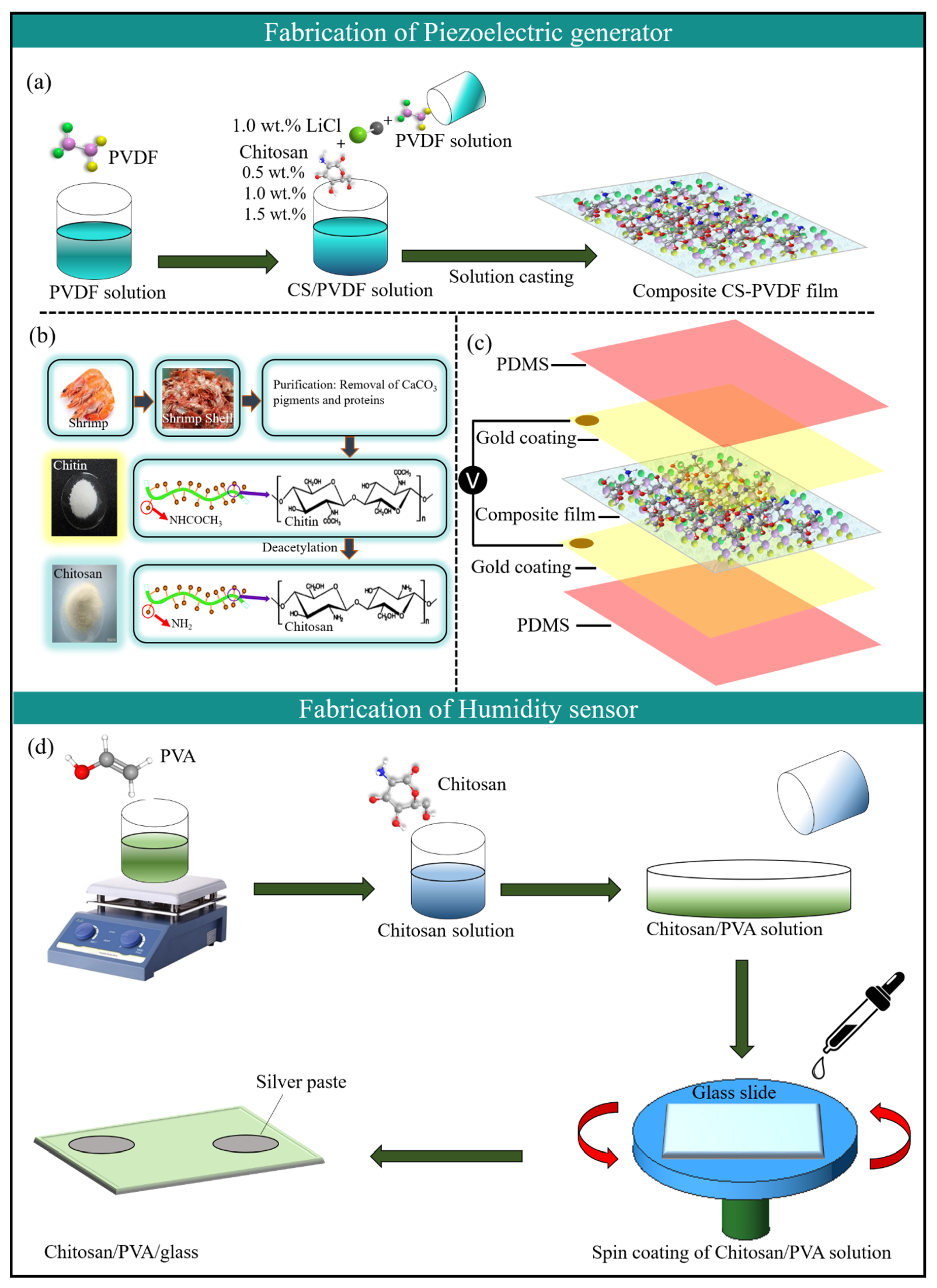
PVDF (8 g) was dissolved in 100 mL of 8 wt.% dimethylformamide (DMF) and stirred at 60 °C until a homogeneous solution was obtained. Generally, 10–12 wt.% PVDF has been used to prepare PVDF membranes [33]. However, the addition of CS can significantly increase the viscosity of a polymer solution [34]. Therefore, a low concentration of 8 wt.% PVDF was used to produce a porous PVDF membrane. Subsequently, three different methods were used to prepare the CS-PVDF blend for the composite film and piezoelectric device. (1) In the first attempt, smaller chitosan particles obtained from shrimp shells (Figure 1b) in a solid form were mixed with the PVDF dope; (2) 1% (w/v) of chitosan was dissolved in 100 mL of 1% (v/v) aqueous acetic acid solution and then mixed with the PVDF dope; and (3) CS particles were suspended in 1% (w/w) LiCl/DMF solution, which was then mixed with the polymer dope. The first and second methods were unsuccessful, because the direct addition of ground CS particles to the PVDF dope did not show characteristic FTIR peaks for chitosan. In addition, when mixed with the PVDF dope, the acetic acid-based chitosan solution formed a gel, which made it impossible to cast a film or sheet. The third method was successful, as it confirmed the presence of chitosan through FTIR analysis. Therefore, this method was selected for further experiments. Different concentrations of CS (0.5, 1, 1.5 wt.%) were loaded onto the previously prepared PVDF dope while keeping the LiCl concentration constant at 1% (w/w). The solutions were stirred to mix them properly, followed by degassing to remove bubbles. The resulting solutions were poured onto a glass Petri dish and dried in an electric oven to evaporate the solvent. Composite CS-PVDF-based films were obtained with thicknesses of 0.51, 0.97, and 1.38 mm, which were cut into the following dimensions: 4 cm × 4 cm. To devise a piezoelectric nanogenerator, both sides of the films were coated with 100 nm of gold to act as the electrodes. The electrode area was maintained at 3 cm × 3 cm. To measure the electrical output of the device, thin conducting copper wires were attached to the opposite sides of the gold electrodes using silver paste. The entire device was packed within a PDMS layer with dimensions of 5 cm × 5 cm. The fabrication of the composite film and PNG device is shown schematically in Figure 1. The designed PNG unit was polarized for 12 h at room temperature to improve the piezoelectric polarization.

2.2. Fabrication of the CS-PVA-Based Composite Film and HS

For the preparation of the CS-PVA-based composite sensing film, 1% (w/v) chitosan was dissolved in 100 mL of 1% (v/v) aqueous acetic acid solution. The mixture was continuously stirred for 24 h at room temperature until a homogenous solution was obtained. PVA was dissolved in MilliQ water and stirred for 2 h at 80 °C to obtain a 5% (w/v) solution. The PVA solution was added to the chitosan solution prepared earlier with different CS-PVA volume ratios of 90/10 70/30, 50/50 and 40/60. The mixtures were stirred for 1 h at room temperature. Afterwards, the prepared CS-PVA solutions were spun onto glass slides using a spin coater, followed by drying to remove excess water molecules. The samples were then cooled to room temperature, and two silver electrodes were diagonally attached using silver paste. The electrical connections were made using thin conductive copper wires. A control film of chitosan was fabricated by following the same procedure but without the addition of PVA. The fabrication mechanism of the humidity sensor is schematically displayed in Figure 1d.

3. Characterization

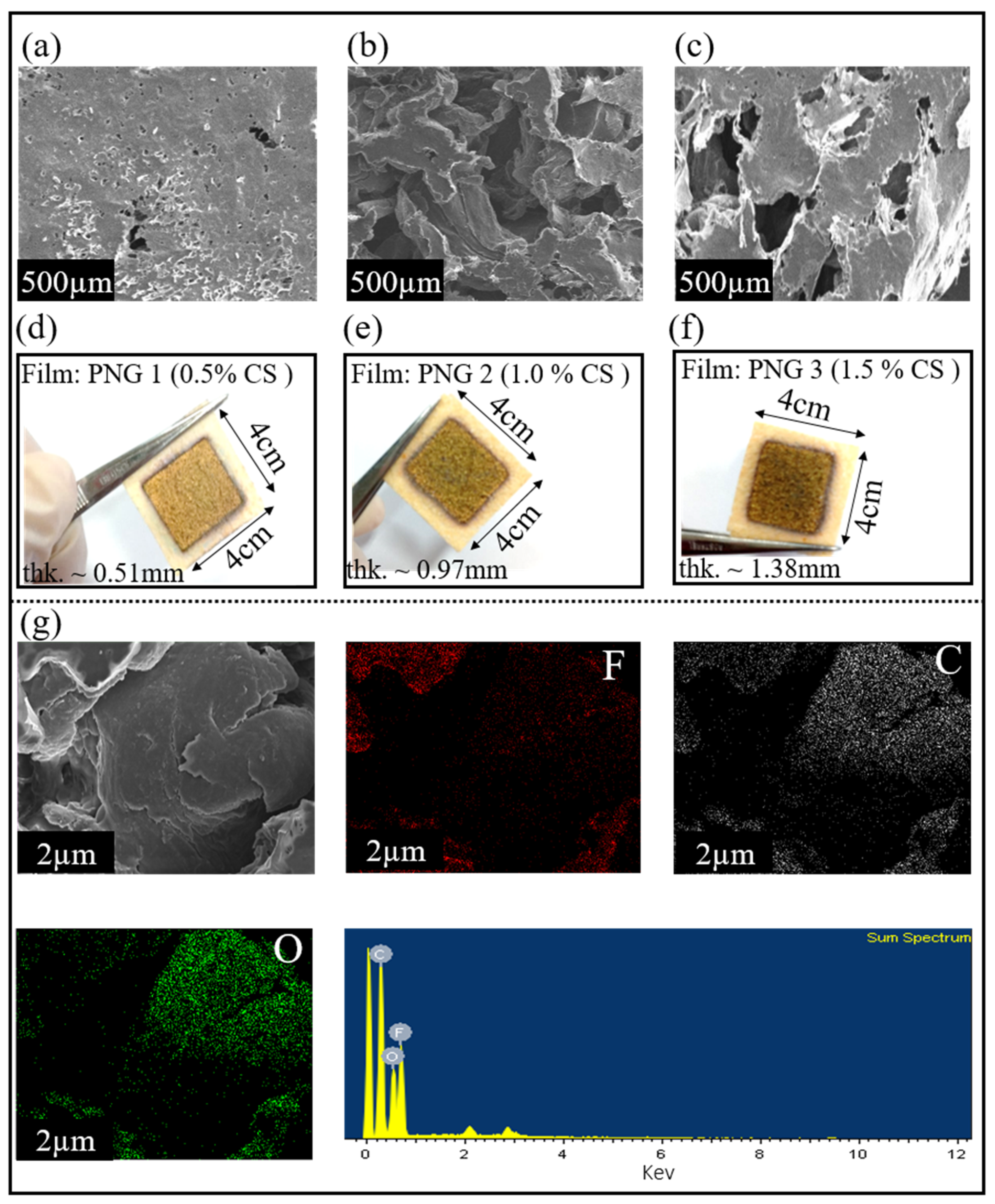
The surface morphologies of the pure PVDF and composite (PVDF-CS) films were analyzed using scanning electron microscopy (SEM). Figure 2a reveals that the composite (PVDF-CS) film containing 0.5 wt.% of chitosan has a smooth morphology. Figure 2b shows that the membrane pore size and surface roughness increased with increasing concentration of chitosan, ensuring a large surface area. However, increasing the chitosan concentration beyond 1 wt.% decreases the surface area, as can be seen in Figure 2c. This change in the structure could be attributed to the high concentration of chitosan, leading to poor penetration of CS particles into the membrane pores, resulting in the formation of a thicker film. Moreover, the elemental composition of the materials was identified using EDS analysis. Figure 2g shows the EDS mapping of fluoride (F), oxygen (O), and carbon (C) in the composite (CS-PVDF) film. PVDF ((C2H2F2) n) does not contain oxygen; however, chitosan does, because of the presence of the hydroxyl (-OH) group. The EDS maps show the distribution of oxygen, confirming the presence of chitosan in the composite film.
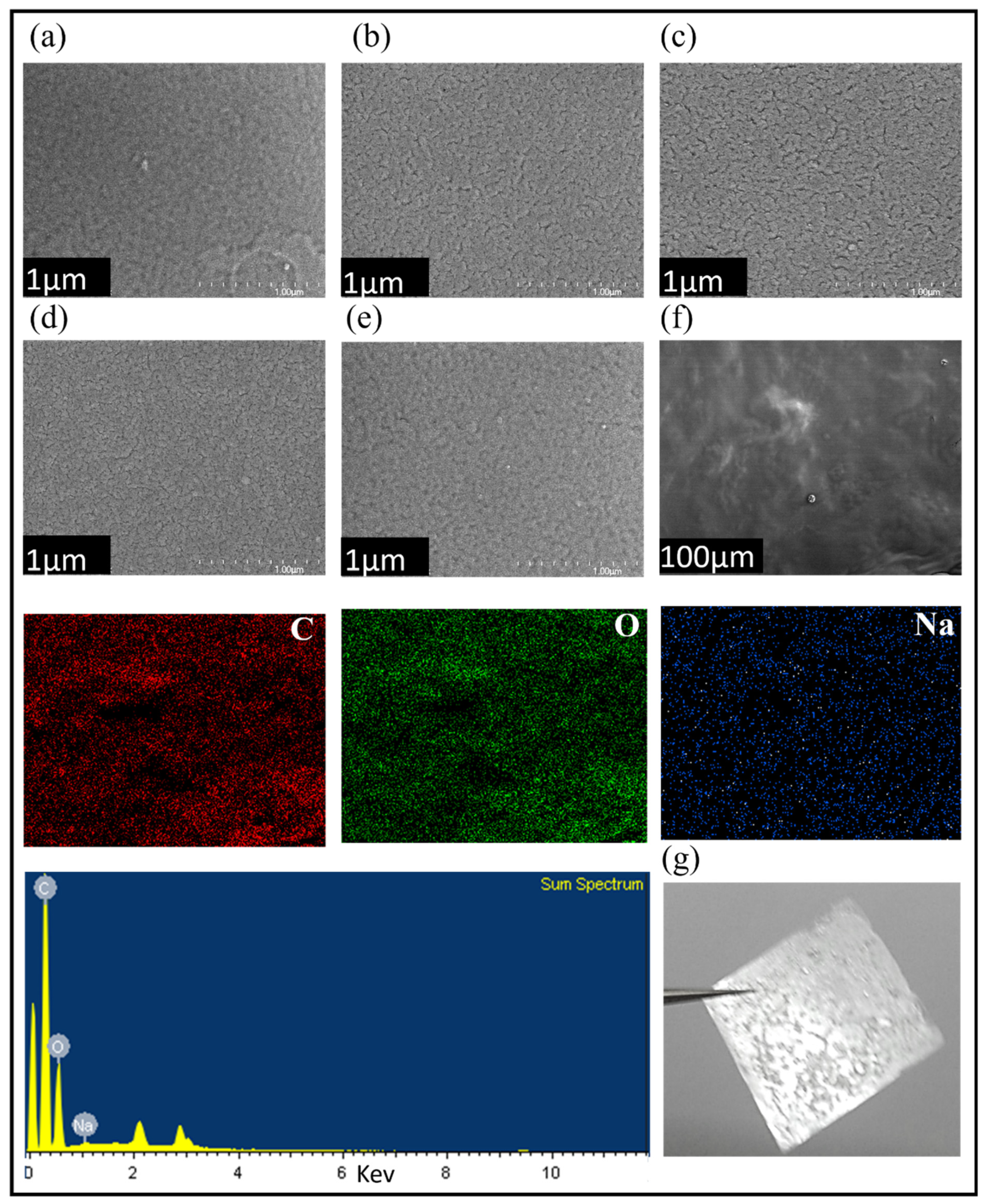
Similarly, the surface morphologies of the pure PVA and composite (CS-PVA) films were investigated using scanning electron microscopy (SEM). From the SEM results shown in Figure 3, it can be observed that CS-PVA composite with 70/30 of volume ratio (Figure 3c) have good microstructure compared to the rest of the CS-PVA composites with volume ratio of 90/10, 50/50 and 40/60. This means that there is an optimum CS-PVA volume ratio that improves the mixing of chitosan and PVA with good microstructure. The EDS analysis shows the elemental composition, which is uniformly distributed over the entire surface of the CS-PVA blend. The characteristic peaks of carbon (C), oxygen (O) and sodium (Na) elements owing to the CS-PVA polymeric blend are shown in Figure 3f.
FTIR analysis was performed to study the chemical interactions between PVDF and chitosan in all of the CS-PVDF composite films, as shown in Figure 4a. The functional groups from the pure chitosan spectra are recognizable, as the strong band between 3600 and 3000 cm−1 corresponds to O-H and N-H stretching, while the band ranging from 2800 to 3000 cm−1 is related to C-H stretching. The characteristic bands at 1508 and 1634 cm−1 indicate NH vibrations in the amino group and C=O stretching of the N-acetyl group, respectively. The composite CS-PVDF films showed absorption peaks for chitosan at approximately 3230 cm−1, although the peaks were not intense. Moreover, there are two notable phenomena: (1) the composite film containing 0.5% CS, which clearly shows no CS characteristics peaks, and (2) the intensity of the CS peaks also increases with increasing chitosan concentration. Notably, the LiCl concentration was maintained at 1% in all the composite films, whereas the CS concentration was allowed to vary. Similarly, the FTIR spectra of the sensing film (CS-PVA) were compared, as shown in Figure 4b. In the case of the pure chitosan film, the characteristic peak at 3338 cm−1 is related to O-H and N-H stretching, while the peak at 2905 cm−1 corresponds to C-H stretching. The addition of PVA to the chitosan results in a decrease in intensity. In addition, the CS-PVA composite film displays an absorption peak at approximately 3234 cm−1 as a result of O-H and C-H asymmetric stretching from PVA [35].

4. Results and Discussion

This work describes in detail the fabrication process and working mechanism of a self-powered HS enabled by the piezoelectric effect. First, composite (CS-PVDF) films of different thicknesses were evaluated based on their piezoelectric capabilities. Furthermore, a parallel connection was established between the piezoelectric generator and HS (both CS and CS-PVA) to demonstrate its self-powered sensing capabilities against different percentages of RH. The electrical output generated from the piezoelectric harvester was used to drive the HS. The output results reveal that the energy-harvesting device and HS lead the path for the future in the field of self-powered sensors.
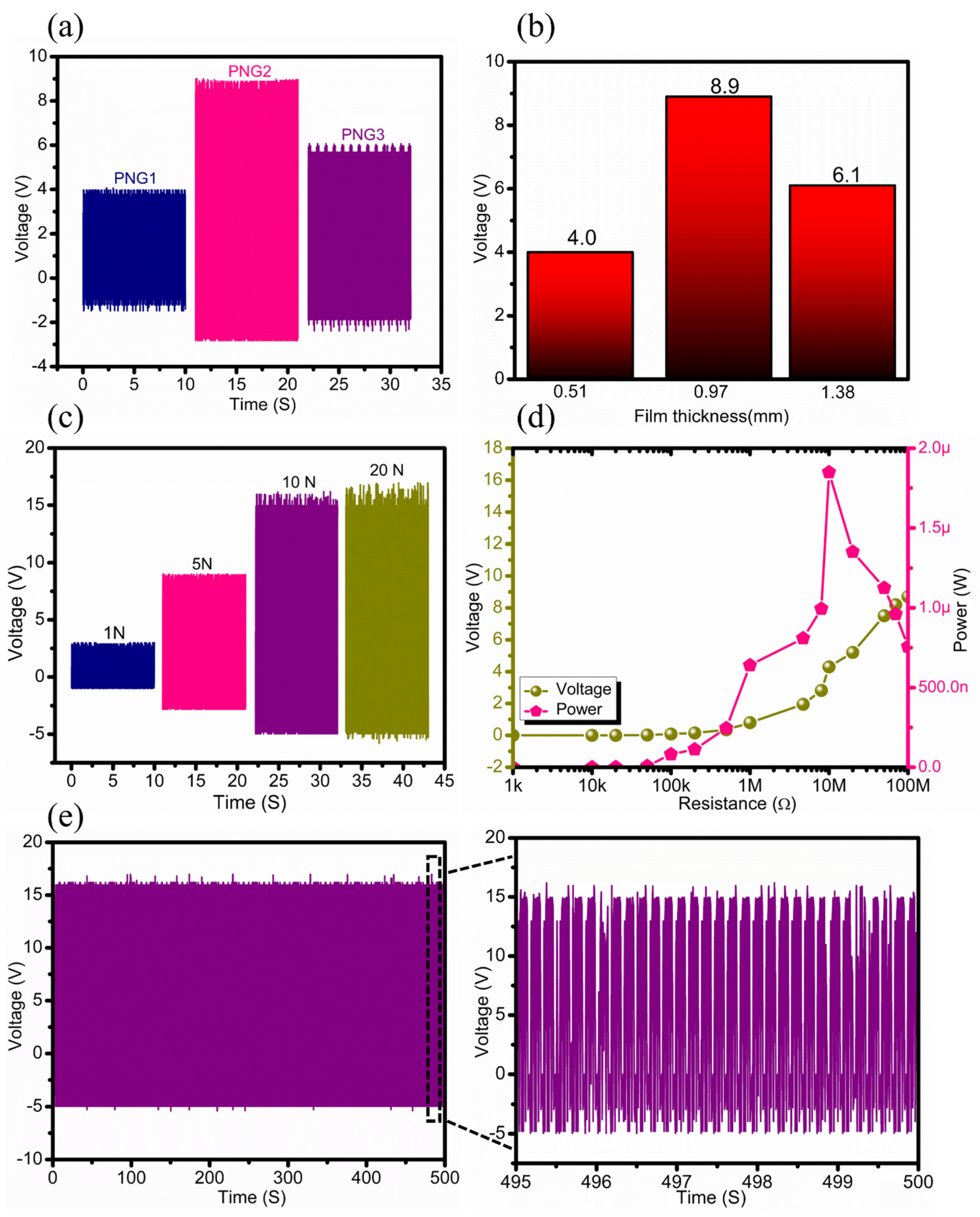
As mentioned previously, CS-PVDF-based composite films with different CS concentrations and different film thicknesses, such as 0.51 mm, 0.97 mm, and 1.38 mm were used to devise PNG1, PNG2, and PNG3 devices, respectively. The fabricated piezoelectric generators were evaluated based on their electrical output performance (electrical) under a constant mechanical force of 5 N, as shown in Figure 5a. The generated output voltage reached a maximum value of Voc ~ 8.9 V for the PNG2 device. The PNG1 and PNG3 devices showed a lower output voltage than the PNG2 device, as shown in Figure 5a. This change in the output performance of the PNG3 device can be attributed to the high concentration of chitosan (1.5 wt.%), which leads to poor penetration of CS particles into the PVDF membrane, and results in the formation of a relatively thicker film with less surface area and in a lower output performance. In addition, lower concentrations of chitosan (0.5 wt.%) cause the improper distribution of CS particles into the PVDF membrane, which limits the output performance of PNG1. Therefore, PNG2 was preferred for further studies because it has the highest output performance among the other two piezoelectric devices (PNG1 and PNG3).
Furthermore, the electrical output response of the PNG2 device was tested under different mechanical forces ranging from 1 N to 20 N, as shown in Figure 5c. The figure shows that increasing the compressive force (from 1 to 10 N) causes an increase in the output response of PNG2. However, the output response of the PNG was stabilized with a further increase in the mechanical force, as there was no significant change in the output performance, as shown in Figure 5c. This means that PNG2 exhibits better performance at a compressive force of 10 N, which is favorable for further studies. The load resistance analysis was carried out by deploying external resistances to monitor the power output of the PNG2 device, as shown in Figure 5d. A stability test of the device was performed, as shown in Figure 5e. Moreover, the PNG device was operated at three different frequencies (0.5 Hz, 1 Hz and 2 Hz). The relationship between the generated voltage and the frequency of changes of the force applied to the PNG device is shown in Figure S1 in the Supplementary Materials.
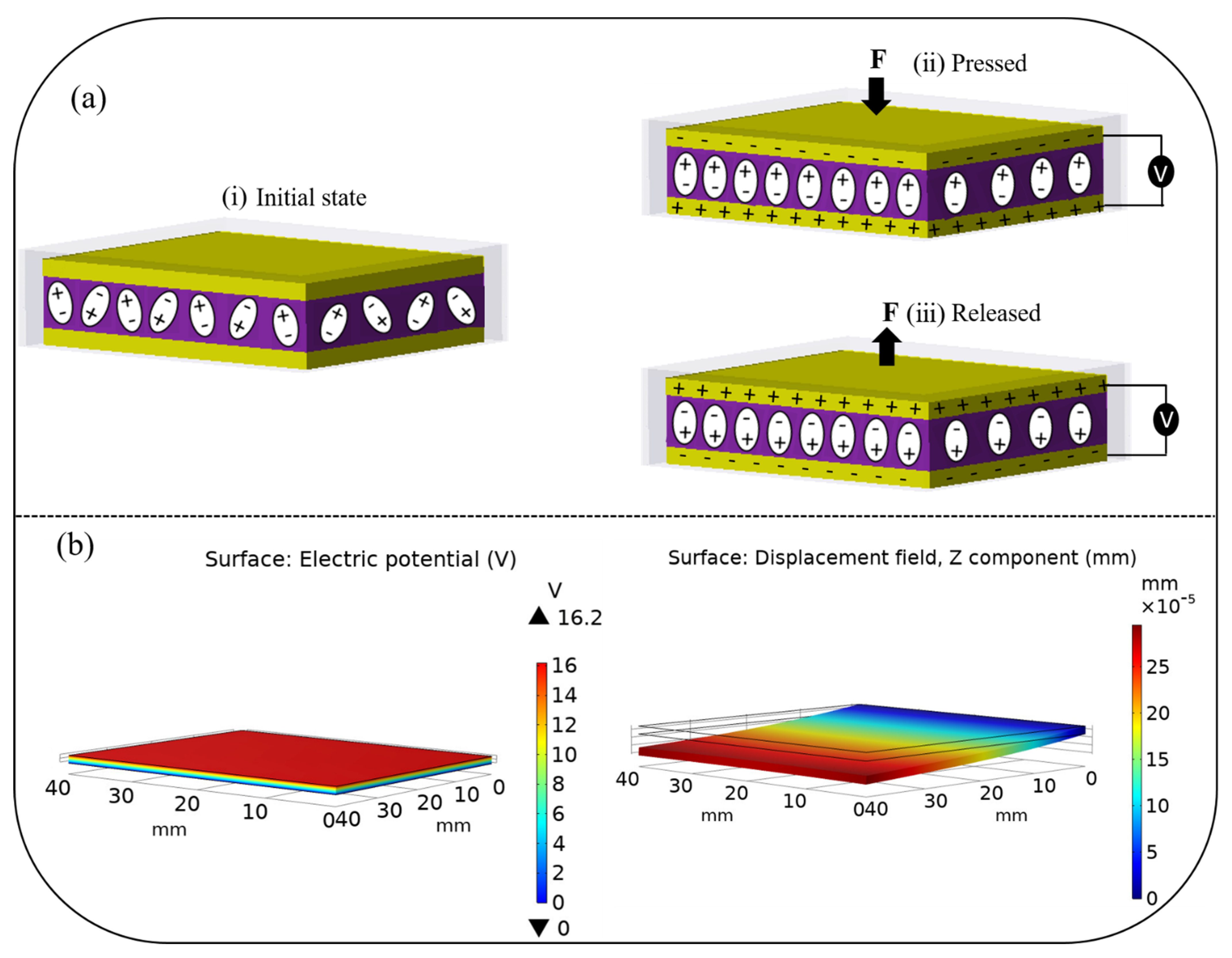
The working mechanism of the PNG device under compressive force is schematically shown in Figure 6a. Initially, there is no piezoelectric potential, and the surface charges are exactly balanced in the absence of an external force. However, deforming the structure of piezoelectric crystals by employing an external force results in the alignment of the dipoles. The surface charges become unbalanced, which produces a net electric charge on the crystal surface. Hence, the charge starts flowing from one electrode to another through an external circuit. To maintain the charge balance after the external force is removed, the electric dipoles are aligned in the opposite direction, during which a reverse signal is generated. Furthermore, the reverse piezoelectric effect was simulated in COMSOL to investigate the mechanical energy produced by the PNG in response to applied electrical energy, as shown in Figure 6b.
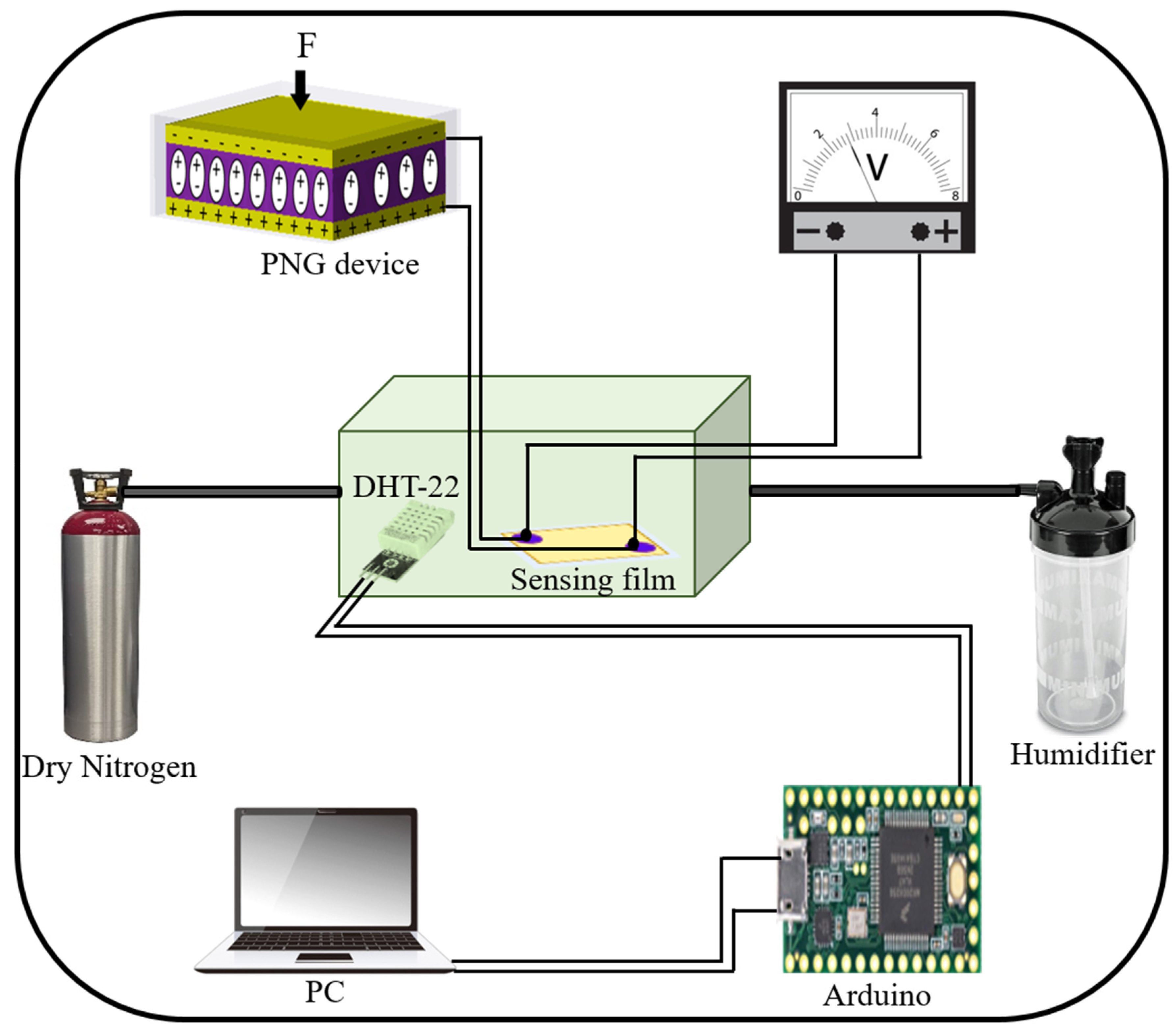
After studying the structural and piezoelectric properties of the CS-PVDF-based PNG device, humidity analysis was performed to examine the affinity of both the CS and CS-PVA films for water molecules. The force was applied perpendicular to the planer surface of the PNG device. Accordingly, a parallel connection was individually established between the PNG device and HSs (CS and CS-PVA) to determine the sensing behavior on the basis of the IV characteristics, as well as its potential to operate as a self-powered system. The humidity-sensing experiment was performed in a customized humidity chamber, and the humidity within the chamber was controlled using a humidifier and nitrogen. A commercially available humidifier was used to regulate the humidification level between 0% RH and 100% inside the chamber. Dry nitrogen gas (N2) was used to adjust the dehumidification level inside the chamber. Furthermore, to monitor the humidity level inside the chamber, a commercially available DHT-22 sensor was employed as a reference HS with a measuring range of 0 to 100% with a 2–5% accuracy. The reference sensor was connected to an Arduino and PC for data acquisition. The detailed humidity-sensing mechanism is illustrated in Figure 7. Meanwhile, an optical image of the operating humidity-sensing mechanism is given in Figure S2 in the Supplementary Materials.
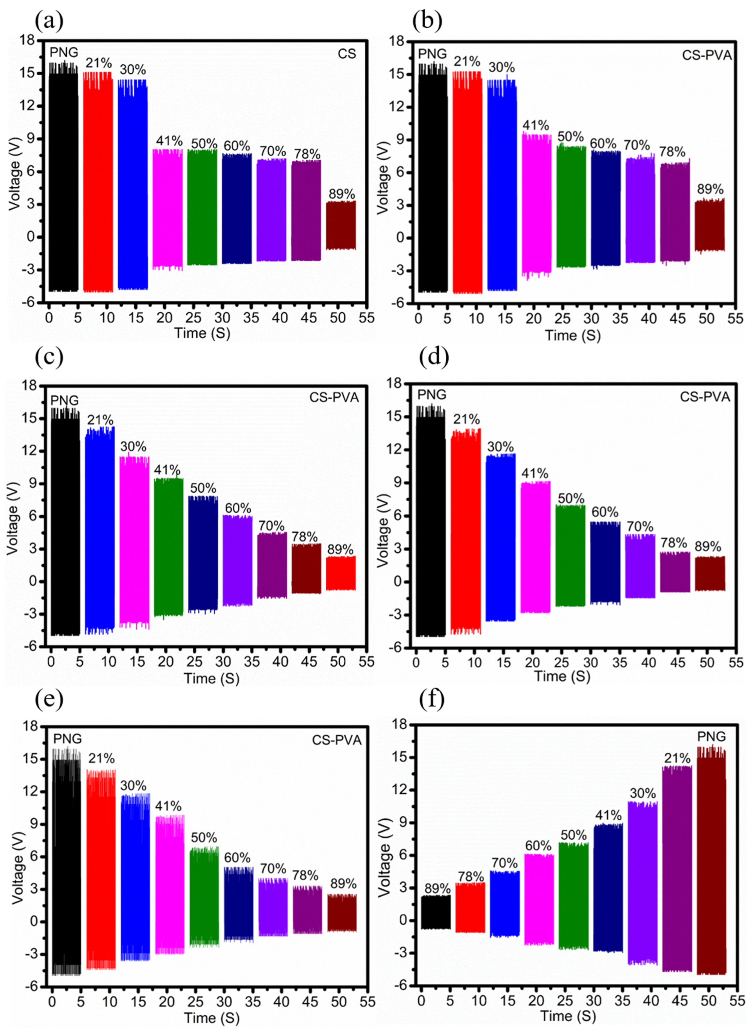
The PNG device was given a constant force of 10 N using a linear motor, and the derived electrical output from the PNG was fed as an input to both the CS- and CS-PVA-based humidity sensors in succession to determine the humidity-sensing response on the basis of the I–V measurement. The humidity-sensing performance of the CS-based humidity sensor is shown in Figure 8a. When the sensor was exposed to water molecules, the VOC decreased with increasing %RH, as can be seen in Figure 8a. At low RH, between 0% and 30%, a small change in voltage could be attributed to the exposure of the chitosan sensor to very few hydrophilic functional groups for chemisorption of water molecules. However, a dramatic decrease in voltage values was observed in the range of 30% RH to 41% RH. This is due to the physisorption of water molecules onto the surface of the previously chemisorbed water molecules. With a further increase in relative humidity (41% RH to 78% RH), excessive water molecules were chemisorbed by the internal hydrophilic group, leading to a slight reduction in the voltage values. Again, sharp decrements in the voltage values were recorded in the high relative humidity environment (78% RH to 89%RH). This was caused by the physisorption of additional water molecules in the chitosan sensing film.
The sensing mechanism of the CS-PVA-based humidity sensors with different volume ratios (90/10, 70/30, 50/50 and 40/60) of CS-PVA were tested with different ranges of relative humidity as shown in Figure 8. Meanwhile, Figure 9 demonstrates the linearity between the voltage and percentage of RH on the basis of the correlation coefficient and sensitivity of both the CS and CS-PVA-based sensors. According to the results, the CS-PVA (70/30) HS showed better sensitivity and linearity compared to others. This means that the CS-PVA-based humidity sensor with a volume ratio of 70/30 facilitates a good microstructure, resulting in better sensitivity (0.23 V/% RH) and linearity (R2 = 0.981), as shown in Figure 9c. It should also be noted here that all the CS-PVA-based humidity sensors exhibit a better humidity-sensing response than the CS-based HS. This can be attributed to the greater number of hydrophilic functional groups in the CS-PVA. To validate the experiment, the same tests were repeated for other devices that exhibited high repeatability, and a 5% error was observed. Therefore, the CS-PVA-based HS with volume ratio of (70/30) was chosen for further studies with respect to its humidity-sensing properties.
Figure 8f demonstrates the desorption response of the 70/30 (CS-PVA)-based HS. Meanwhile, Figure 9f shows the adsorption and desorption responses, which exhibited a small humidity hysteresis of ~3.8% RH in the humidity range of 21% to 89% RH. The larger response value and wider detection range of the CS-PVA-based HS operated by a piezoelectric generator confirms that the fabricated HS is a favorable candidate for humidity detection and possesses remarkable advantages in the field of self-powered humidity detection. The proposed self-powered humidity-sensing device can target various applications, such as in remote areas where power delivery is not frequently available. The Internet of Things (IOT)-based nodes that must deliver continuous power to sensors for operation can be qualified by just pressing once on the sensor to obtain an instantaneous relative humidity reading of the environment. Similarly, this can also be a robust candidate for green roads or paths on which humans might normally walk, as the walking force can easily enable our proposed sensor to generate voltage proportional to the humidity at that point of time. Moreover, this study provides the prototype with all required characterizations.

5. Conclusions

In this study, chitosan (CS) and chitosan-polyvinyl alcohol (CS-PVA)-based sensing films and a piezoelectric nanogenerator, which acted as humidity sensors and a power generator, respectively, were successfully fabricated. The piezoelectric generator performance was tested on different concentrations of chitosan (0.5,1.0, and 1.5 wt.%) in the CS-PVDF composite material. The enhanced initial output voltage of CS-PVDF composite piezoelectric material, which contains 1.0 wt.% of chitosan, was attributed to its rough surface structure and large surface area. Similarly, the performance of the humidity sensor was investigated based on the volume ratio of CS/PVA in the composite polymeric blend. According to the results, the CS-PVA HS with a volume ratio of 70/30 showed better performance compared to CS-PVA HSs with different volume ratios (90/10, 50/50 and 40/60). This is because of the good microstructure, which was facilitated by an optimized amount of chitosan and PVA. Moreover, the affinity of CS- and CS-PVA-based humidity sensors toward water molecules was investigated at different humidity levels in a closed electronically controlled chamber. The as-developed self-powered device provided an output relation inverse to the humidity in the environment. Moreover, the sensor showed excellent performance, including high linearity (R2 = 0.981) and sensitivity (0.23 V/% RH), with a wide detection capability in the range of 21% to 89% RH. This work is intended to consolidate self-powered technology in humidity-sensing mechanisms, proposing its candidature for a variety of applications.
Supplementary Materials

The following supporting information can be downloaded at: https://www.mdpi.com/article/10.3390/en15207609/s1, Figure S1: Voltage output at different frequencies of impact vibrations measured across a load resistance of 10 Mohms; Figure S2: Operating setup of self-powered humidity testing and data acquisition.

Author Contributions

Conceptualization, Z.; Funding acquisition, S.C.; Methodology, Z. and A.M.S.; Project administration, S.C.; Resources, S.C.; Supervision, S.C.; Validation, Z. and S.C.; Writing–original draft, Z.; Writing–review & editing, Z. and A.M.S. All authors have read and agreed to the published version of the manuscript.

Funding

This research was funded by National Research Foundation of Korea (NRF-2020M3A9E4104385), Korea Environment Industry & Technology Institute (KEITI) through “Technology Development Project for Biological Hazards Management in Indoor Air” Project, funded by Korea Ministry of Environment (MOE)(G232021010381) and GRRC program of Gyeonggi province (GRRC-Gachon2020(B01), Analysis of AI-based Medical Information.

Data Availability Statement

The raw/processed data required to reproduce these findings cannot be shared at this time due to legal or ethical reasons.

Conflicts of Interest

The authors declare no conflict of interest.

References

  1. Trung, T.Q.; Lee, N.-E. Flexible and Stretchable Physical Sensor Integrated Platforms for Wearable Human-Activity Monitoringand Personal Healthcare. Adv. Mater. 2016, 28, 4338–4372. [Google Scholar] [CrossRef]
  2. Shabnam, L.; Faisal, S.N.; Roy, A.K.; Haque, E.; Minett, A.I.; Gomes, V.G. Doped graphene/Cu nanocomposite: A high sensitivity non-enzymatic glucose sensor for food. Food Chem. 2017, 221, 751–759. [Google Scholar] [CrossRef] [PubMed]
  3. Zhao, J.; Li, N.; Yu, H.; Wei, Z.; Liao, M.; Chen, P.; Wang, S.; Shi, D.; Sun, Q.; Zhang, G. Highly Sensitive MoS2 Humidity Sensors Array for Noncontact Sensation. Adv. Mater. 2017, 29, 1702076. [Google Scholar] [CrossRef] [PubMed]
  4. Yadav, R.; Sahu, L.; Beig, G.; Tripathi, N.; Jaaffrey, S. Ambient particulate matter and carbon monoxide at an urban site of India: Influence of anthropogenic emissions and dust storms. Environ. Pollut. 2017, 225, 291–303. [Google Scholar] [CrossRef] [PubMed]
  5. Joshi, S.R.; Kim, B.; Kim, S.K.; Song, W.; Park, K.; Kim, G.H.; Shin, H. Low-cost and fast-response resistive humidity sensor comprising biopolymer-derived carbon thin film and carbon microelectrodes. J. Electrochem. Soc. 2020, 167, 147511. [Google Scholar] [CrossRef]
  6. Hernández-Rivera, D.; Rodríguez-Roldán, G.; Mora-Martínez, R.; Suaste-Gómez, E. A Capacitive Humidity Sensor Based on an Electrospun PVDF/Graphene Membran. Sensors 2017, 17, 1009. [Google Scholar] [CrossRef] [PubMed] [Green Version]
  7. He, C.; Korposh, S.; Correia, R.; Liu, L.; Hayes-Gill, B.R.; Morgan, S.P. Optical fibre sensor for simultaneous temperature and relative humidity measurement: Towards absolute humidity evaluation. Sens. Actuators B Chem. 2021, 344, 130154. [Google Scholar] [CrossRef]
  8. Su, P.-G.; Lu, P.-H. Electrical and Humidity-Sensing Properties of Impedance-Type Humidity Sensors that Were Made of Ag Microwires/PPy/SnO2 Ternary Composites. Chemosensors 2020, 8, 92. [Google Scholar] [CrossRef]
  9. Le, X.; Liu, Y.; Peng, L.; Pang, J.; Xu, Z.; Gao, C.; Xie, J. Surface acoustic wave humidity sensors based on uniform and thickness controllable graphene oxide thin films formed by surface tension. Microsyst. Nanoeng. 2019, 5, 36. [Google Scholar] [CrossRef] [Green Version]
  10. Delapierre, G.; Grange, H.; Chambaz, B.; Destannes, L. Polymer-based capacitive humidity sensor: Characteristics and experimental results. Sens. Actuators 1983, 4, 97–104. [Google Scholar] [CrossRef]
  11. Shah, J.; Kotnala, R.; Singh, B.; Kishan, H. Microstructure-dependent humidity sensitivity of porous MgFe2O4–CeO2 ceramic. Sens. Actuators B Chem. 2007, 128, 306–311. [Google Scholar] [CrossRef]
  12. McGhee, J.R.; Sagu, J.S.; Southee, D.J.; Evans, P.S.A.; Wijayantha, K.G.U. Printed, Fully Metal Oxide, Capacitive Humidity Sensors Using Conductive Indium Tin Oxide Inks. ACS Appl. Electron. Mater. 2020, 2, 3593–3600. [Google Scholar] [CrossRef]
  13. Chen, W.-P.; Zhao, Z.-G.; Liu, X.-W.; Zhang, Z.-X.; Suo, C.-G. A Capacitive Humidity Sensor Based on Multi-Wall Carbon Nanotubes (MWCNTs). Sensors 2009, 9, 7431–7444. [Google Scholar] [CrossRef] [PubMed]
  14. Tsai, J.T.; Lu, C.-C.; Li, J.G. Fabrication of humidity sensors by multi-walled carbon nanotubes. J. Exp. Nanosci. 2010, 5, 302–309. [Google Scholar] [CrossRef]
  15. Bi, H.; Yin, K.; Xie, X.; Ji, J.; Wan, S.; Sun, L.; Terrones, M.; Dresselhaus, M.S. Ultrahigh humidity sensitivity of graphene oxide. Sci. Rep. 2013, 3, 2714. [Google Scholar] [CrossRef] [PubMed] [Green Version]
  16. Borini, S.; White, R.; Wei, D.; Astley, M.; Haque, S.; Spigone, E.; Harris, N.; Kivioja, J.; Ryhänen, T. Ultrafast Graphene Oxide Humidity Sensors. ACS Nano 2013, 7, 11166–11173. [Google Scholar] [CrossRef] [PubMed]
  17. Zhao, Z.; Duan, Y. A low cost fiber-optic humidity sensor based on silica sol–gel film. Sens. Actuators B Chem. 2011, 160, 1340–1345. [Google Scholar] [CrossRef]
  18. Zampetti, E.; Pantalei, S.; Pecora, A.; Valletta, A.; Maiolo, L.; Minotti, A.; Macagnano, A.; Fortunato, G.; Bearzotti, A. Design and optimization of an ultra thin flexible capacitive humidity sensor. Sens. Actuators B Chem. 2009, 143, 302–307. [Google Scholar] [CrossRef]
  19. Sisman, O.; Kaur, N.; Sberveglieri, G.; Núñez-Carmona, E.; Sberveglieri, V.; Comini, E. UV-Enhanced Humidity Sensing of Chitosan–SnO2 Hybrid Nanowires. Nanomaterials 2020, 10, 329. [Google Scholar] [CrossRef] [PubMed] [Green Version]
  20. Crini, G.; Badot, P.-M. Application of chitosan, a natural aminopolysaccharide, for dye removal from aqueous solutions by adsorption processes using batch studies: A review of recent literature. Prog. Polym. Sci. 2008, 33, 399–447. [Google Scholar] [CrossRef]
  21. Kumar, S.; Koh, J. Physiochemical and optical properties of chitosan based graphene oxide bionanocomposite. Int. J. Biol. Macromol. 2014, 70, 559–564. [Google Scholar] [CrossRef]
  22. Voznesenskiy, S.; Sergeev, A.; Mironenko, A.; Bratskaya, S.; Kulchin, Y. Integrated-optical sensors based on chitosan waveguide films for relative humidity measurements. Sens. Actuators B Chem. 2013, 188, 482–487. [Google Scholar] [CrossRef]
  23. Shantini, D.; Nainggolan, I.; Nasution, T.I.; Derman, M.N.; Mustaffa, R.; Wahab, N.Z.A. Hexanal Gas Detection Using Chitosan Biopolymer as Sensing Material at Room Temperature. J. Sens. 2016, 2016, 8539169. [Google Scholar] [CrossRef] [Green Version]
  24. Rathke, T.D.; Hudson, S.M. Review of Chitin and Chitosan as Fiber and Film Formers. J. Macromol. Sci. Part C Polym. Rev. 1994, 34, 375–437. [Google Scholar] [CrossRef]
  25. Chen, L.; Li, T.; Chan, C.; Menon, R.; Balamurali, P.; Shaillender, M.; Neu, B.; Ang, X.; Zu, P.; Wong, W.; et al. Chitosan based fiber-optic Fabry–Perot humidity sensor. Sens. Actuators B Chem. 2012, 169, 167–172. [Google Scholar] [CrossRef]
  26. Li, Z.; Chen, J.; Yang, J.; Su, Y.; Fan, X.; Wu, Y.; Yu, C.; Wang, Z.L. [Small Beta]-Cyclodextrin Enhanced Triboelectrification for Self-powered Phenol Detection and Electrochemical Degradation. Energy Environ. Sci. 2015, 8, 887–896. [Google Scholar] [CrossRef]
  27. Zhu, D.; Fu, Y.; Zang, W.; Zhao, Y.; Xing, L.; Xue, X. Piezo/active humidity sensing of CeO2/ZnO and SnO2/ZnO nanoarray nanogenerators with high response and large detecting range. Sens. Actuators B Chem. 2014, 205, 12–19. [Google Scholar] [CrossRef]
  28. Guo, H.; Chen, J.; Tian, L.; Leng, Q.; Xi, Y.; Hu, C. Airflow-Induced Triboelectric Nanogenerator as a Self-Powered Sensor for Detecting Humidity and Airflow Rate. ACS Appl. Mater. Interfaces 2014, 6, 17184–17189. [Google Scholar] [CrossRef] [PubMed]
  29. Zhao, T.; Fu, Y.; Sun, C.; Zhao, X.; Jiao, C.; Du, A.; Wang, Q.; Mao, Y.; Liu, B. Wearable biosensors for real-time sweat analysis and body motion capture based on stretchable fiber-based triboelectric nanogenerators. Biosens. Bioelectron. 2022, 205, 114115. [Google Scholar] [CrossRef] [PubMed]
  30. Xu, S.; Qin, Y.; Xu, C.; Wei, Y.; Yang, R.; Wang, Z.L. Self-powered nanowire devices. Nat. Nanotechnol. 2010, 5, 366–373. [Google Scholar] [CrossRef] [PubMed]
  31. Lee, M.; Bae, J.; Lee, J.; Lee, C.-S.; Hong, S.; Wang, Z.L. Self-powered environmental sensor system driven by nanogenerators. Energy Environ. Sci. 2011, 4, 3359–3363. [Google Scholar] [CrossRef]
  32. Vivekananthan, V.; Alluri, N.R.; Purusothaman, Y.; Chandrasekhar, A.; Selvarajan, S.; Kim, S.-J. Biocompatible Collagen Nanofibrils: An Approach for Sustainable Energy Harvesting and Battery-Free Humidity Sensor Applications. ACS Appl. Mater. Interfaces 2018, 10, 18650–18656. [Google Scholar] [CrossRef]
  33. Kang, G.; Cao, Y. Application and modification of poly(vinylidene fluoride) (PVDF) membranes—A review. J. Membr. Sci. 2014, 463, 145–165. [Google Scholar] [CrossRef]
  34. Costa, C.N.; Teixeira, V.G.; Delpech, M.C.; Souza, J.V.S.; Costa, M.A. Viscometric study of chitosan solutions in acetic acid/sodium acetate and acetic acid/sodium chloride. Carbohydr. Polym. 2015, 133, 245–250. [Google Scholar] [CrossRef] [Green Version]
  35. Pandele, A.M.; Ionita, M.; Crica, L.; Dinescu, S.; Costache, M.; Iovu, H. Synthesis, characterization, and in vitro studies of graphene oxide/chitosan–polyvinyl alcohol films. Carbohydr. Polym. 2014, 102, 813–820. [Google Scholar] [CrossRef]
Figure 1. (a) Schematic illustration of the fabrication process for the CS-PVDF-based PNG film, (b) schematic illustration of the conventional process for chitosan preparation from shrimp shells, (c) schematic diagram of the developed piezoelectric nanogenerator, (d) schematic illustration of the fabrication process for the CS-PVA-based humidity sensing film.
Energies 15 07609 g001
Figure 2. SEM images, digital photographs and EDS mapping of CS-PVDF-based composite films (a) 0.5% CS-PVDF, (b) 1.0% CS-PVDF, (c) 1.5% CS-PVDF, (d) 0.5% CS-PVDF film used in PNG 1 device, (e) 1.0% CS-PVDF film used in PNG 2 device, (f) 1.5% CS-PVDF film used in PNG 3 device, and (g) EDS maps for F, N, and O in 1% CS-PVDF film.
Energies 15 07609 g002
Figure 3. SEM images, digital photographs, and EDS mapping of PVA and composite CS-PVA blends with different volume ratios: (a) PVA, (b) 90/10 CS-PVA, (c) 70/30 CS-PVA, (d) 50/50 CS-PVA, (e) 40/60 CS-PVA, (f) EDS mapping for C, O and Na in 70/30 CS-PVA polymeric blend, (g) humidity-sensing film with 70/30 CS-PVA volume ratio.
Energies 15 07609 g003
Figure 4. FTIR spectra for pure CS, CS-PVDF, and CS-PVA composite materials: (a) different concentrations of CS in PVDF dope while maintaining LiCl concentration constant at 1%; (b) FTIR spectra of CS and CS-PVA.
Energies 15 07609 g004
Figure 5. (a) Electrical response of PNG devices (PNG1, PNG2, PNG3) under a mechanical force of 5 N; (b) film thickness of CS-PVDF-based piezoelectric film and its corresponding output performance; (c) voltage response of the optimized PNG2 device when different mechanical forces were applied ranging from 1 N to 20 N; (d) output power of the PNG2 device at different load resistances; (e) stability test for a period of 500 s at 10 N force and surface morphology of piezoelectric films.
Energies 15 07609 g005
Figure 6. (a) Direct piezoelectric effect, the working mechanism of the piezoelectric device; (b) Comsol simulation of the reverse piezoelectric effect.
Energies 15 07609 g006
Figure 7. Block diagram of the self-powered humidity testing and data acquisition setup.
Energies 15 07609 g007
Figure 8. Voltage response of CS- and CS-PVA-based humidity sensors when increasing relative humidity from 21% to 89% RH under a mechanical force of 10 N. (a) CS-based HS, (b) 90/10 (CS-PVA) HS, (c) 70/30 (CS-PVA) HS, (d) 50/50 (CS-PVA) HS, (e) 40/60 (CS-PVA) HS, and (f) voltage response of the (70/30) CS-PVA-based humidity sensor when the relative humidity varied from 89% to 21% RH.
Energies 15 07609 g008
Figure 9. Sensitivity and linear relationships between the RH and voltage values of CS- and CS-PVA-based HSs: (a) CS-based HS, (b) 90/10 (CS-PVA) HS, (c) 70/30 (CS-PVA) HS, (d) 50/50 (CS-PVA) HS, (e) 40/60 (CS-PVA) HS, and (f) hysteresis curve of 70/30 (CS-PVA) humidity sensor.
Energies 15 07609 g009
Publisher’s Note: MDPI stays neutral with regard to jurisdictional claims in published maps and institutional affiliations.