1. Introduction
Distributed cooperative control of AC microgrids relies on consensus and containment approaches to accomplish frequency regulation [
1] and voltage containment [
2], respectively. The distributed communication network among inverters poses security concerns as individual inverters lack the global perspective with limited information exchanged among neighboring inverters [
3,
4,
5,
6]. Some existing methods detect, identify, and then isolate or recover the compromised inverters [
7,
8,
9] but would require a number of inverters to be healthy. Moreover, stealthy attacks launched by intelligent attackers are generally undetectable. Specifically, attackers could exploit the intrinsic characteristics or internal dynamics of the system modeling and/or configuration to launch deliberately designed attacks without being detected by existing attack-detection algorithms [
10]. The vulnerability assessment and consequences of power system state estimation with respect to such unobservable or undetectable false data injection (FDI) attacks were presented in [
10,
11,
12,
13]. Protection and prevention against stealthy and intelligent attackers are not always possible using the attack-detection methods, and a paradigm shift to enhance the self-resilience of the large-scale networked microgrids by developing attack-resilient control protocols is the overarching objective for safeguarding the nation’s critical infrastructures.
Distributed resilient control protocols were investigated recently in [
14,
15,
16,
17,
18,
19,
20,
21] to provide self-resilience against external attacks without detecting and identifying the compromised agents. The above-mentioned resilient control protocols for microgrids mainly deal with disturbances, noises, and/or faults that are unintentionally caused and are assumed to be bounded. However, in practice, malicious attackers could launch unknown and unbounded FDI attacks to maximize their damage, distorting cooperative performance and even leading to system instability [
22]. To address unbounded FDI attacks for AC microgrids, an attack-resilient control framework, using observer-based techniques, was studied in [
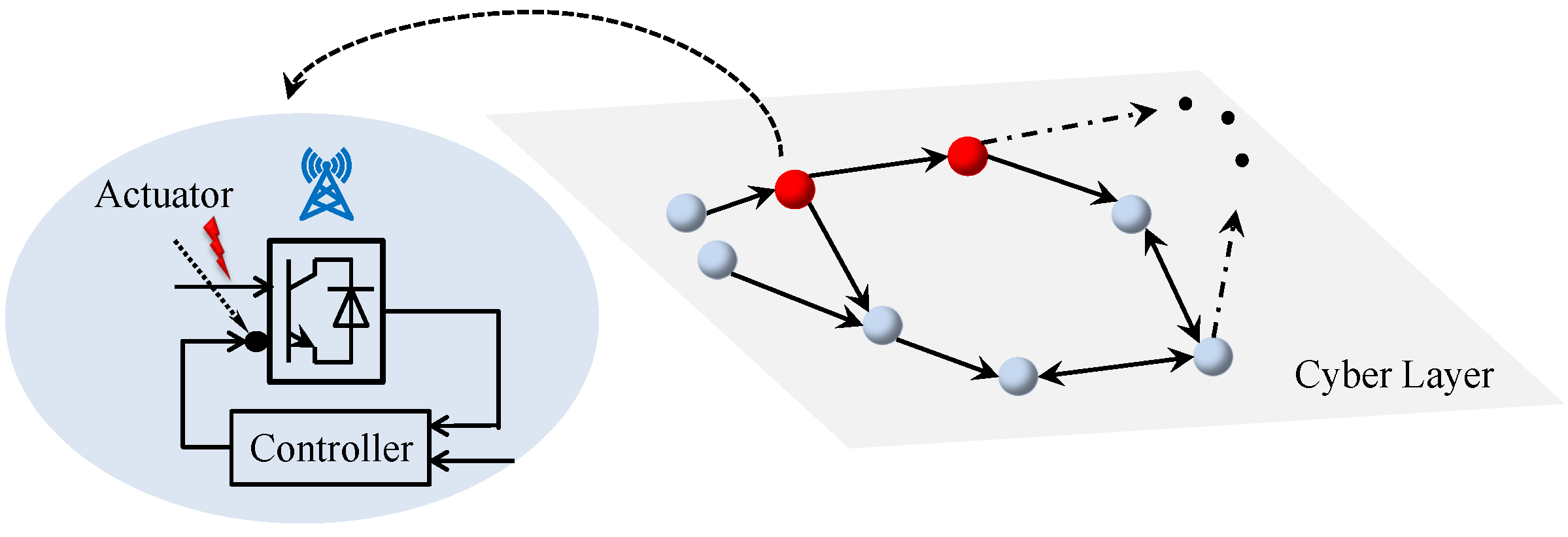
2] to maintain the bounded frequency regulation and voltage containment at the cost of additional communication channels among observers. Alternatively, this paper explores adaptive techniques to address unknown unbounded attacks on input signals of the control loops, which are referred to as the actuator attacks. This paper considers the unbounded actuator attacks on both frequency and voltage control loops of an inverter, as illustrated in
Figure 1, which could severely destabilize the synchronization mechanism among microgrid inverters. The contributions of this paper are two-fold:
A resilient control method is proposed for both secondary frequency and voltage control loops in the face of unknown unbounded actuator attacks. Compared to the observer-based techniques in [
2], this control method does not need additional cyber layers for information exchange among observers, offering reduced computational complexity and system vulnerability to cyber attacks.
A stability analysis using Lyapunov techniques shows that the proposed method is resilient to unbounded actuator attacks by preserving the uniformly ultimately bounded (UUB) consensus for frequency regulation and voltage containment. Moreover, the ultimate bound can be set by adjusting the tuning parameters. That is, the frequency and voltage terms can be tuned to converge to an arbitrarily small neighborhood around their respective reference values.
The rest of this paper is organized as follows: Preliminaries on graph theory and notations are given in
Section 2.
Section 3 reviews the conventional cooperative secondary control of AC microgrids.
Section 4 formulates the attack-resilient frequency and voltage control problems. The distributed resilient controller design is discussed in
Section 5. The efficacy of the proposed control method is verified for an AC microgrid in
Section 6.
Section 7 concludes the paper.
2. Preliminaries on Graph Theory and Notations
There are N inverters, with two leader nodes, mapped on a communication network, which is represented by a time-invariant weighted digraph . The interactions among the inverters are represented by a subgraph with the associated adjacency matrix . Define and as the in-degree matrix and the corresponding Laplacian matrix, respectively, where . There are two leader nodes to issue the upper and lower reference values. is the pinning gain from the (upper/lower) leader to the inverter, brought together in the diagonal matrix .
and are the minimum and maximum singular values of a given matrix, respectively. and denote the sets of and , respectively. is a column vector where all entries are one. ⊗, , , and denote the Kronecker product, a block diagonal matrix, the Euclidean norm of a given vector, and the absolute value of a given scalar, respectively.
3. Conventional Cooperative Secondary Control of AC Microgrids
Conventional secondary control acts as an actuator by providing the input control signals for tuning the setpoints of decentralized primary controls. These primary droop mechanisms are given by the following for the
ith inverter
where
and
are the active and reactive powers, respectively.
and
are the operating angular frequency and terminal voltage, respectively.
and
are the setpoints for the primary droop mechanisms fed from the secondary control layer.
and
are
and
droop coefficients selected for each inverter’s power ratings.
We differentiate the droop relations in (
1) and (2), with respect to time, to obtain
where
and
are auxiliary control inputs. To synchronize the terminal frequency and voltage of each inverter to their respective references, the leader–follower containment-based secondary control is adopted [
23]. The local cooperative frequency and voltage control protocols using the relative information with respect to the neighboring inverters and the leaders are given by
where
are positive constant coupling gains.
and
are the frequency and voltage reference values of the
leader, respectively. The frequency reference for both leaders is set as
. The upper and lower leaders have their voltage reference values set as
and
, respectively. The setpoints for the primary-level droop control,
and
, are then computed from
and
as
Using (
5) and (
6) to rewrite (
3) and (4) yields
where
and
. Define
. Then, the global forms of (
9) and (
10) are
where
and
. Define the global frequency and voltage containment error vectors as
Definition 1 (Secondary Frequency Containment Control Objective). The secondary frequency control objective is to make the local frequency of each inverter converge to the range of the two frequency references issued by the upper and lower leaders. Since these two reference values are identical, the frequency regulation is achieved.
Definition 2 (Secondary Voltage Containment Control Objective). The secondary voltage containment control objective is to make each inverter voltage converge to the range spanned by the two references of the upper and lower leaders.
The following assumption is needed for the communication graph topology to guarantee the cooperative consensus.
Assumption 1. The communication graph includes a directed path from, at least, one leader to each inverter.
Lemma 1 ([
24])
. Suppose that Assumption 1 holds; is non-singular and positive-definite. Moreover, the frequency and voltage containment control objectives are achieved if and , respectively. 4. Problem Formulation
This section formulates the resilient secondary frequency and voltage control problems for a networked AC microgrid. In particular, we consider the general unknown unbounded attack injections to the local input channels of both frequency and voltage control loops, which modifies (
9) and (
10) to
where
and
denote the unbounded attack signals injected to the input channels of frequency and voltage control loops at the
inverter, respectively.
Assumption 2. and are bounded.
Remark 1. Assumption 2 is reasonable since attack signals, with an excessively large change in values, could be easily detected in practice. In the event that the attacker does launch an attack signal with an infinite magnitude of the rate of change, the microgrids can incorporate a defensive mechanism to detect and reject such an injection. Since the intentionally injected attacks could be unbounded, the bounded noises and/or disturbances that are unintentionally caused can also be addressed using the attack-resilient controller to be designed.
Since and are unbounded, conventional cooperative control protocols fail to regulate the frequency and voltage terms. One then needs attack-resilient control methods to preserve the frequency regulation and voltage containment performances and to ensure closed-loop stability. The following convergence definition is needed.
Definition 3 ([
25])
. Signal is UUB with an ultimate bound b if there exist positive constants b and c, independent of and, for every , there exist , independent of , such that . Now, the following distributed resilient secondary frequency and voltage control problems are defined.
Definition 4 (Attack-Resilient Frequency Control Problem)
. The goal is to design an input control signal in (
3)
for each inverter such that in (
13)
is UUB under unbounded attacks to the local frequency control loop. That is, the inverter frequency goes to a small neighborhood around the reference value. Definition 5 (Attack-Resilient Voltage Control Problem)
. The goal is to design an input control signal in (4)
for each inverter such that in (
14)
is UUB under unbounded attacks to the local voltage control loop. That is, each inverter voltage goes to a small neighborhood around the range spanned by the two upper and lower references. 5. Distributed Resilient Controller Design
We propose a fully distributed control method to solve the attack-resilient frequency and voltage control problems. For convenience, denote
Then, we present the following attack-resilient control framework for both frequency and voltage control loops
where
and
are given positive constants, and
and
are time-varying coupling weights, with
and
.
Figure 2 shows the communication network among inverters and the proposed secondary control for an inverter.
Theorem 1. Under Assumptions 1 and 2 and using the cooperative resilient frequency control protocols consisting of (
17)
and (
19)
, in (
13)
is UUB. Furthermore, by increasing in (
19)
, the ultimate bound of can be adjusted to be an arbitrarily small value, i.e., inverter frequency converges to an arbitrarily small neighborhood around the reference value. Proof. Consider the Lyapunov function candidate:
□
Combine (
19) and (
21) to obtain
where
.
Recalling Sylvester’s inequality and noting that
is positive-definite, one can then obtain
Next, we prove that
, such that
A sufficient condition to guarantee (
24) is
Since both
and
are non-negative, we further obtain the following sufficient condition:
Note that (
26) is guaranteed if both
and
hold. Since
from Assumption 2,
is bounded. Hence,
is also bounded. Using (
19) and choosing
we then obtain that
, such that (
26) holds. Furthermore, we obtain that (
24) holds. Using (
23), we now obtain that
Therefore,
is bounded. Note that
Hence,
is also bounded. Moreover, using LaSalle’s invariance principle [
26], it is seen from (
29) that
is bounded by
, where
is a positive constant. Hence, the ultimate bound can be reduced by properly increasing the adaptive tuning parameter
in (
19).
Theorem 2. Under Assumptions 1 and 2 and using the cooperative resilient voltage control protocols consisting of (
18)
and (
20)
, in (
14)
is UUB. Furthermore, by increasing in (
20)
, the ultimate bound of can be set arbitrarily small, i.e., the inverter voltage converges to an arbitrarily small neighborhood around the range covered by the two references. Proof. The proof follows that of Theorem 1. □
Remark 2. To mitigate the propagated adverse effects caused by the unbounded actuator attacks, and , the time-varying coupling weights, and , are designed based on adaptive tuning laws. As seen from the proof of Theorem 1, such adaptively updated coupling weights can successfully compensate for the externally injected attack signals.
Remark 3. Compared to [2], the proposed control protocols (
17)–(
20)
have the following merits: (i) Local observers with additional communication information flow were constructed in [2] to estimate the actual state measurements. This, however, could introduce additional computational complexity. Moreover, the additional communication channels for exchanging observer states could potentially increase the system vulnerability to malicious cyber attacks. (ii) While both [2] and this paper preserve the UUB convergences for both frequency and voltage terms, in this paper, the ultimate bound can be reduced by properly increasing the adaptive tuning parameters. 6. Case Studies
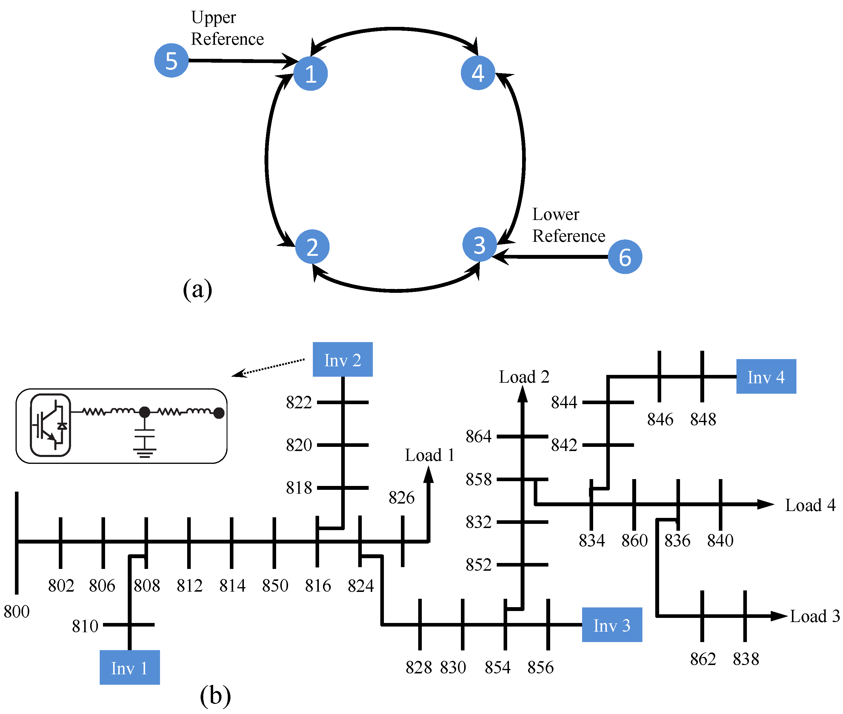
The proposed resilient control method is studied in the context of an IEEE 34-bus feeder system, islanded at bus 800, and augmented with four inverters and two leaders, as shown in
Figure 3. The specifications of inverters and its grid interconnections are adopted from [
1,
27], respectively. Inverters 1 and 2 have twice the power ratings of inverters 3 and 4. The inverter droop gains are set as
,
,
, and
. Inverters communicate on a bidirectional communication network with the adjacency matrix of
. The pinning gains are
. The frequency reference, upper voltage reference, and lower voltage reference are 60 Hz, 340 V, and 330 V, respectively. The unbounded attack injections to the frequency and voltage control loops are set as
and
, respectively. The performance of the resilient control protocols, (
17)–(
20), is compared with the conventional secondary control method in (
5) and (
6). The coupling gains for the conventional control protocols are set as
. The adaptive tuning parameters for the resilient control method are set as
.
Figure 4 compares the frequency response for the proposed and the conventional methods. Under ideal conditions (no attacks), inverters frequencies synchronize to
using both control methods. Once the unbounded attack to frequency control loops is initiated at
s, the conventional method fails to preserve the system stability. By contrast, the proposed resilient method contains frequencies at a small neighborhood around 60 Hz.
Figure 5 shows that, without attacks, both methods share active powers among inverters based on their droop gains. After initiating the unbounded attacks to frequency control loops at
s, the active power performance from the conventional method becomes unstable. Meanwhile, the proposed method contains active powers in a small neighborhood around the value of properly shared powers.
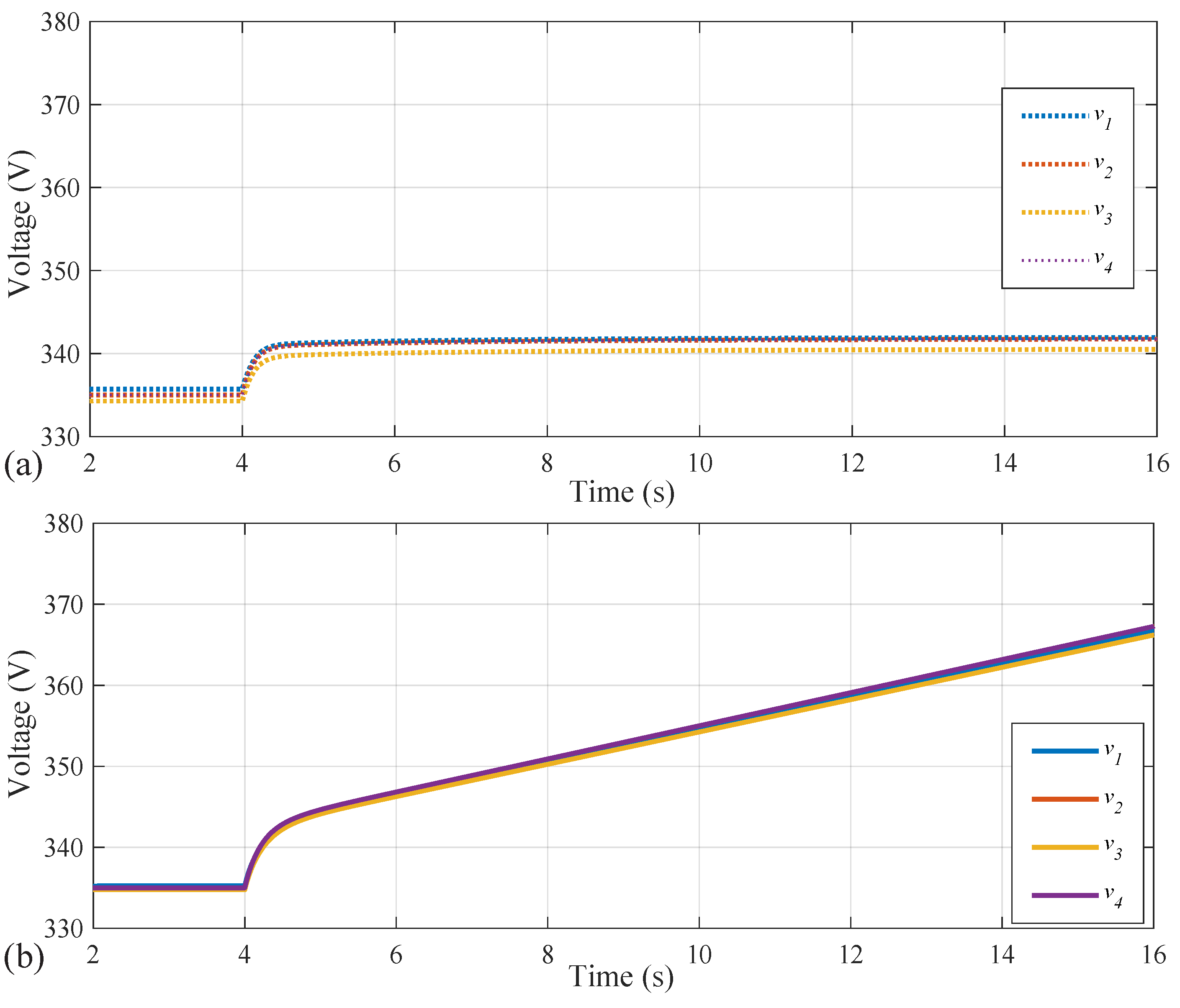
Figure 6 compares inverters’ voltages using both control methods. Without attacks, voltage values stay in the range of
to
. After initiating the unbounded attacks to voltage control loops at
s, the voltages terms using the conventional method diverge, while those produced by the proposed method remain stable within 330∼340V.
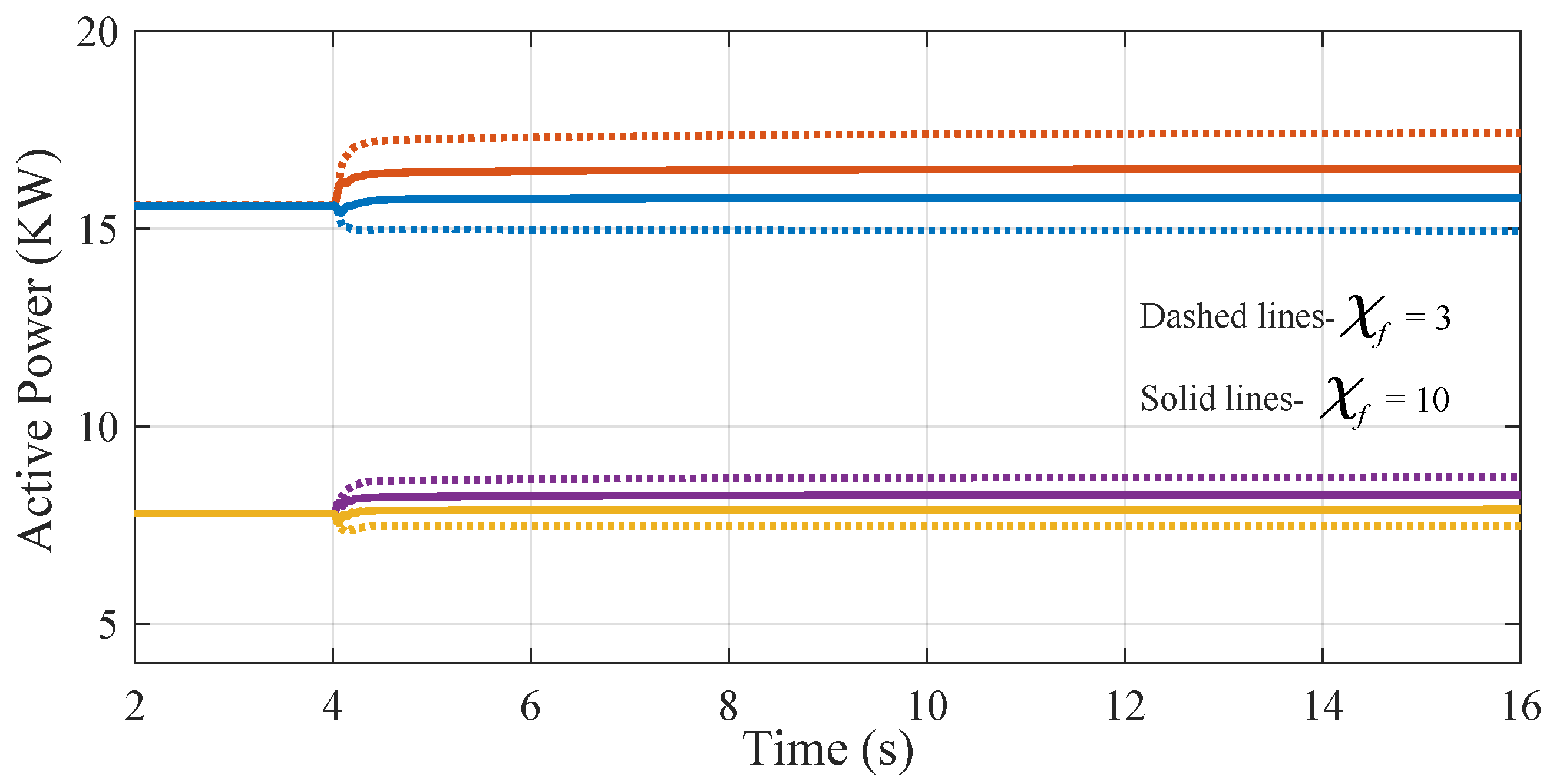
The ultimate bound of the UUB convergence can be adjusted to be an arbitrarily small value by increasing the adaptive tuning parameters.
Figure 7 and
Figure 8 show the frequency and active power waveforms, where the performance with
and
are illustrated with solid and dashed lines, respectively. As seen, the ultimate bound can be reduced by increasing
.
7. Conclusions
This paper presents a novel resilient secondary controller for multi-inverter AC microgrids against unknown unbounded actuator attacks on both frequency and voltage control loops. A fully distributed adaptive control framework ensures the UUB stability of the closed-loop system by preserving the UUB regulation for both frequency and voltage terms. Moreover, the ultimate bound can be set by adjusting the tuning parameters. The resilient performance of the proposed method has been verified using a modified IEEE 34-bus system.
Author Contributions
Conceptualization, S.Z.; methodology, S.Z.; validation, S.Z. and Y.Z.; formal analysis, S.Z. and Y.W.; investigation, S.Z., Y.Z. and Y.W.; resources, S.Z.; data curation, S.Z. and Y.Z.; writing—original draft preparation, S.Z., Y.Z. and Y.W.; writing—review and editing, S.Z., Y.Z. and Y.W.; visualization, Y.Z. and Y.W.; supervision, S.Z.; project administration, S.Z.; funding acquisition, S.Z. All authors have read and agreed to the published version of the manuscript.
Funding
This research received no external funding.
Data Availability Statement
Not applicable.
Conflicts of Interest
The authors declare no conflict of interest.
Abbreviations
The following abbreviations are used in this manuscript:
| AC | Alternating Current |
| FDI | False Data Injection |
| UUB | Uniformly ultimately bounded |
References
- Bidram, A.; Lewis, F.L.; Davoudi, A. Distributed control systems for small-Scale power networks: Using multiagent cooperative control theory. IEEE Control Syst. Mag. 2014, 34, 56–77. [Google Scholar]
- Zuo, S.; Beg, O.A.; Lewis, F.L.; Davoudi, A. Resilient networked AC microgrids under unbounded cyber attacks. IEEE Trans. Smart Grid 2020, 11, 3785–3794. [Google Scholar] [CrossRef]
- Kosut, O.; Jia, L.; Thomas, R.J.; Tong, L. Malicious data attacks on the smart grid. IEEE Trans. Smart Grid 2011, 2, 645–658. [Google Scholar] [CrossRef]
- Sridhar, S.; Hahn, A.; Govindarasu, M. Cyber–physical system security for the electric power grid. Proc. IEEE 2011, 100, 210–224. [Google Scholar] [CrossRef]
- He, H.; Yan, J. Cyber-physical attacks and defences in the smart grid: A survey. IET Cyber-Phys. Syst. Theory Appl. 2016, 1, 13–27. [Google Scholar] [CrossRef]
- Deng, R.; Xiao, G.; Lu, R.; Liang, H.; Vasilakos, A.V. False data injection on state estimation in power systems—Attacks, impacts, and defense: A survey. IEEE Trans. Industr. Inform. 2016, 13, 411–423. [Google Scholar] [CrossRef]
- Beg, O.A.; Nguyen, L.V.; Johnson, T.T.; Davoudi, A. Signal temporal logic-based attack detection in DC microgrids. IEEE Trans. Smart Grid 2018, 10, 3585–3595. [Google Scholar] [CrossRef]
- Zhang, J.; Sahoo, S.; Peng, J.C.-H.; Blaabjerg, F. Mitigating concurrent false data injection attacks in cooperative DC microgrids. IEEE Trans. Power Electron. 2021, 36, 9637–9647. [Google Scholar] [CrossRef]
- Tan, S.; Guerrero, J.M.; Xie, P.; Han, R.; Vasquez, J.C. Brief survey on attack detection methods for cyber-physical systems. IEEE Syst. J. 2020, 14, 5329–5339. [Google Scholar] [CrossRef]
- Liu, Y.; Ning, P.; Reiter, M.K. False data injection attacks against state estimation in electric power grids. ACM Trans. Inf. Syst. Secur. 2011, 14, 1–33. [Google Scholar] [CrossRef]
- Hug, G.; Giampapa, J.A. Vulnerability assessment of AC state estimation with respect to false data injection cyber-attacks. IEEE Trans. Smart Grid 2012, 3, 1362–1370. [Google Scholar] [CrossRef]
- Liang, J.; Sankar, L.; Kosut, O. Vulnerability analysis and consequences of false data injection attack on power system state estimation. IEEE Trans. Power Syst. 2015, 31, 3864–3872. [Google Scholar] [CrossRef]
- Pan, K.; Teixeira, A.; Cvetkovic, M.; Palensky, P. Cyber risk analysis of combined data attacks against power system state estimation. IEEE Trans. Smart Grid 2018, 10, 3044–3056. [Google Scholar] [CrossRef]
- Chen, Y.; Qi, D.; Dong, H.; Li, C.; Li, Z.; Zhang, J. A FDI attack-resilient distributed secondary control strategy for islanded microgrids. IEEE Trans. Smart Grid 2020, 12, 1929–1938. [Google Scholar] [CrossRef]
- Liu, X.-K.; Wen, C.; Xu, Q.; Wang, Y.-W. Resilient control and analysis for DC microgrid system under DoS and impulsive FDI attacks. IEEE Trans. Smart Grid 2021, 12, 3742–3754. [Google Scholar] [CrossRef]
- Lu, J.; Zhang, X.; Hou, X.; Wang, P. Generalized extended state observer-based distributed attack-resilient control for DC microgrids. IEEE Trans. Sustain. Energy 2022, 13, 1469–1480. [Google Scholar] [CrossRef]
- Deng, C.; Wang, Y.; Wen, C.; Xu, Y.; Lin, P. Distributed resilient control for energy storage systems in cyber–physical microgrids. IEEE Trans. Industr. Inform. 2020, 17, 1331–1341. [Google Scholar] [CrossRef]
- Abhinav, S.; Modares, H.; Lewis, F.L.; Ferrese, F.; Davoudi, A. Synchrony in networked microgrids under attacks. IEEE Trans. Smart Grid 2017, 9, 6731–6741. [Google Scholar] [CrossRef]
- Dehkordi, N.M.; Baghaee, H.R.; Sadati, N.; Guerrero, J.M. Distributed noise-resilient secondary voltage and frequency control for islanded microgrids. IEEE Trans. Smart Grid 2018, 10, 3780–3790. [Google Scholar] [CrossRef]
- Shahab, M.A.; Mozafari, B.; Soleymani, S.; Dehkordi, N.M.; Shourkaei, H.M.; Guerrero, J.M. Distributed consensus-based fault tolerant control of islanded microgrids. IEEE Trans. Smart Grid 2019, 11, 37–47. [Google Scholar] [CrossRef]
- Afshari, A.; Karrari, M.; Baghaee, H.R.; Gharehpetian, G.B.; Karrari, S. Cooperative fault-tolerant control of microgrids under switching communication topology. IEEE Trans. Smart Grid 2019, 11, 1866–1879. [Google Scholar] [CrossRef]
- Fawzi, H.; Tabuada, P.; Diggavi, S. Secure estimation and control for cyber-physical systems under adversarial attacks. IEEE Trans. Automat. Contr. 2014, 59, 1454–1467. [Google Scholar] [CrossRef]
- Han, R.; Meng, L.; Ferrari-Trecate, G.; Coelho, E.A.A.; Vasquez, J.C.; Guerrero, J.M. Containment and consensus-baed distributed coordination control to achieve bounded voltage and precise reactive power sharing in islanded AC microgrids. IEEE Trans. Ind. Appl. 2017, 53, 5187–5199. [Google Scholar] [CrossRef]
- Zuo, S.; Song, Y.; Lewis, F.L.; Davoudi, A. Output containment control of linear heterogeneous multi-agent systems using internal model principle. IEEE Trans. Cybern. 2017, 47, 2099–2109. [Google Scholar] [CrossRef] [PubMed]
- Khalil, H.K. Nonlinear Systems, 3rd ed.; Prentice-Hall: Upper Saddle River, NJ, USA, 2002. [Google Scholar]
- LaSalle, J. Some extensions of Liapunov’s second method. IRE Trans. Circuit. Theory 1960, 7, 520–527. [Google Scholar] [CrossRef]
- Mwakabuta, N.; Sekar, A. Comparative study of the IEEE 34 node test feeder under practical simplifications. In Proceedings of the 2007 39th North American power symposium, Las Cruces, NM, USA, 30 September–2 October 2007. [Google Scholar]
| Publisher’s Note: MDPI stays neutral with regard to jurisdictional claims in published maps and institutional affiliations. |
© 2022 by the authors. Licensee MDPI, Basel, Switzerland. This article is an open access article distributed under the terms and conditions of the Creative Commons Attribution (CC BY) license (https://creativecommons.org/licenses/by/4.0/).


