1. Introduction
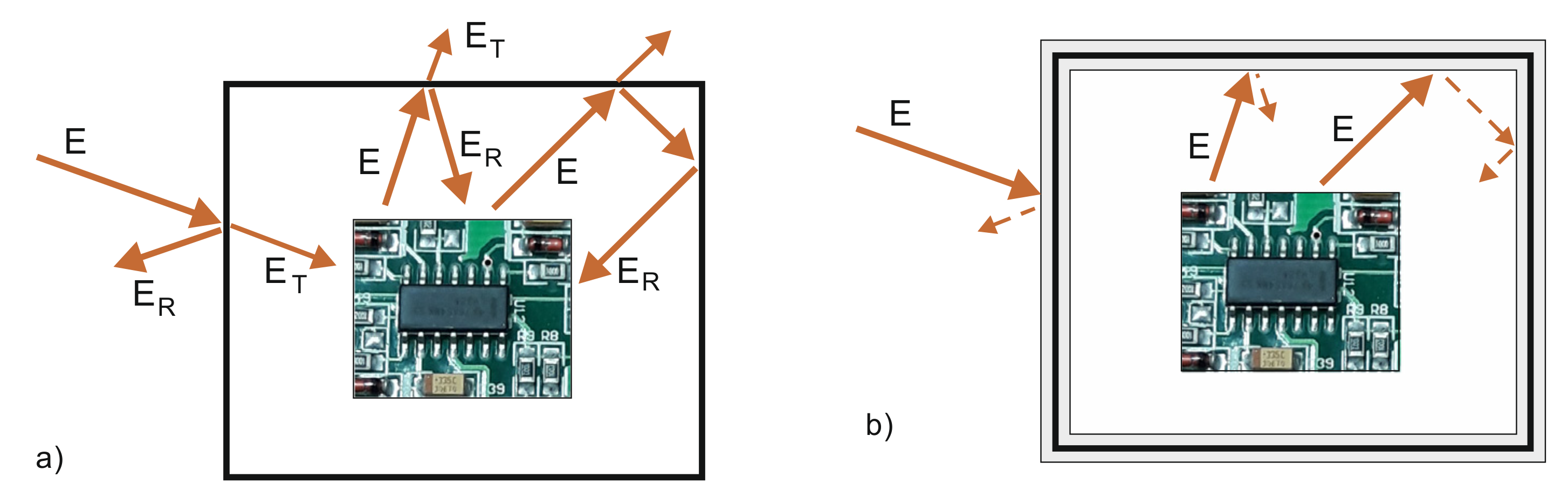
Sensitive electronic devices and digital systems must be protected against harmful external electromagnetic radiation. In addition, such devices must also be protected against internal radiation generated by their own electronic elements. The mobile terminals are examples of self-radiation circuits. Terminals work in the useful frequency ranges (GSM, DCS, UMTS etc.), but unwanted radiation is also generated by processors in the range of 200–300 MHz. Such internal radiation can affect the operation of a system and can also be harmful to humans because such frequencies can penetrate deeper into tissues of the head than cellular frequencies. The symbolic presentation of external and internal radiation incidents to an electronic circuit is shown in
Figure 1a. In this schematic figure, the electronic circuit is placed inside a metallic or metallic-like enclosure, which is a typical configuration giving, in many cases, rather poor protection against the external electromagnetic field. Such an enclosure reflects incident radiation causing the internal as well as external reflected rays. In both cases, the reflected electromagnetic field should be minimized as far as possible. The reduction of external reflections is especially important in the case of military devices or objects that must remain hidden from the enemy. Currently, there are microwave sources based on magnetron or klystron which emit high-power microwave pulses with an output power of up to 80 MW [
1]. Such radiation can be used as a microwave weapon in order to destroy or damage unprotected electronic circuits.
To solve these issues, much effort is focused on the design and exploration of different forms of protection. To this end, electromagnetic absorbers are widely utilized in both civil and military applications since these materials can absorb the microwave energy of the incident field—see
Figure 1b.
Absorbing materials impose different electrical and mechanical requirements; therefore, various types of absorbers have been developed. However, general requirements for a good absorber include high absorbing properties, as well as a low value of reflectance. Another important requirement is the frequency broadband properties. Microwave absorbers are generally based on graphite and are provided in different structural forms such as nanotubes, nanowires or flakes [
2,
3,
4]. Such absorbers guarantee excellent electromagnetic protection properties due to the high value of electric losses. From this point of view, carbon-based materials have attracted the attention of many researchers in the manufacture of a variety of components for practical applications. However, the high value of energy reflected from carbon-based materials is a significant disadvantage of these absorbers. To avoid this problem, the volumetric absorbers have pyramidal forms that make it possible to reflect radiation in various directions as well as to dissipate electromagnetic energy into heat. On the other hand, shielding absorbers can be made as flat films or inks with convoluted patterns [
5,
6]. Quiang et al. [
7] presented an absorber based on carbon with a modified microstructure. This material was the yolk-shell C@C microspheres, which exhibits good absorption properties. Another form of reduction of reflection coefficient is the supplementation of the structure with components improving the magnetic properties of the material. In such cases, carbon-like material is enriched with chemical elements that improve permeability [
8,
9]. Qing et al. [
2] discussed advantages of multi-walled carbon nanotubes and carbonyl iron particles.
In the work, the microwave reflectance of graphite was compared with one of the graphene derivatives - reduced graphene oxide, which is a prospective form of carbon. The flake graphite was purchased from Asbury Carbons (Asbury, NJ, USA). The reduced graphene oxide was prepared at Łukasiewicz Institute of Microelectronics and Photonics. These carbon materials were investigated in their pure forms without any additives. Obtained data have been the basic information about constitutive properties of such materials. Typically, these materials are available in the form of powders; the electrical properties, presented in the literature, have been measured when they were immersed in the polystyrene foam, resin, wax, etc. In such cases, values of permittivity and permeability depended significantly on the proportional participation of the fillers and did not present the properties of pure materials. In the work, the solid state was obtained by pressing them in the special housing using 2 kN force.
The paper is organized as follows. Values of S-parameters of material samples of graphite and RGO were measured to determine complex permittivity and permeability. The obtained data were used to investigate the reflectance of material slabs on conductive layers.
2. Graphite
Graphite is one of the allotropic forms of carbon. It is made up of numerous carbon monolayers bound together by weak van der Waals forces. Each individual carbon layer is made up of hexagonal aromatic carbon rings that form a honeycomb structure. Due to its low price and numerous properties, such as low weight, high aspect ratio, high electrical conductivity, good thermal and mechanical stability, it is an attractive component in applications related to energy, electronic and optical devices. A serious disadvantage of graphite is the difficulty in obtaining good dispersion in various solvents. This can be remedied by functionalizing graphite by treatment with acids, e.g., HCl and H2SO4. A major limitation in the practical applications of graphite is its poor magnetic properties. This problem can be solved by mechanically combining graphite with iron compounds, which results in a synergistic effect and gives graphite magnetic properties, increasing its electromagnetic efficiency in the microwave area.
3. Reduced Graphene Oxide (RGO)
Reduced graphene oxide (RGO) belongs to the family of derivatives of flake graphene. It is obtained by the oxidation of graphite to graphite oxide and then exfoliation to graphene oxide (GO). Graphene oxide has plenty of various oxygen groups which cause numerous structural defects and the loss of electrical conductivity. In order to partially restore the aromatic structure and recover the electrical conductivity, GO is reduced, e.g., chemically by means of various reducing agents, such as N2H4 xH2O (hydrazine hydrate), NaBH4, NaOH, NaH2PO2 H2O etc. In RGO (the final product), the oxygen functional groups are partially removed but some of them always remain. RGO is a promising material with a variety of potential applications in many technical areas and is a relatively well-studied carbon/graphene derivative. Its production is cost-effective. The material itself has many valuable properties; it is flexible, achieves excellent electrical/thermal conductivity and has outstanding barrier properties. In addition, the remaining functional groups and defects in the RGO structure improve impedance mismatch, electron dipole relaxation and defect polarization relaxation. All types of defects presumably increase absorption, not reflection, as was observed with carbon nanotubes and graphite.
4. Method Section
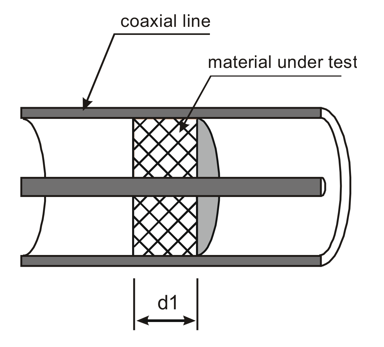
To determine the reflectance of graphite and RGO, the constitutive material parameters, such as permittivity and permeability, have been determined. The measurements of these parameters were realized in a coaxial line. Samples of measured materials had a toroidal shape—see
Figure 2. To obtain the solid form of powdered material for measurement without any matrix, it was pressed in a special housing using 2 kN force. The housing was made of steel and had the same geometry as the coaxial line. The interior of housing had an external diameter of 7.0 mm and internal diameter of 3.04 mm. Prepared powder with determined weight was poured into the housing and was pressed using the special piston. The thickness of the sample
d1 (see
Figure 2) was determined individually for each sample. The density of the graphite samples was 2.07 g/cm
3, while RGO was 1.55 g/cm
3.
4.1. Measurement of Material Properties
The electromagnetic properties can be described macroscopically by scalar material properties in terms of relative complex permittivity and permeability:
where:
ε′, μ′ are the electric and magnetic constants and ε″, μ″ are the electric and magnetic loss factors.
There are numerous methods and techniques of measuring material parameters. Each of these techniques has advantages and disadvantages and should be adopted individually. In the case of shielding materials, a rather broad frequency band is recommended, as they must protect against electromagnetic interference of unknown frequencies. As opposed to the free space technique, the rectangular or coaxial transmission lines guarantee the easiest calibration techniques. With rectangular waveguides, a simple geometry of a sample can be used; however, the frequency bands are limited. On the other hand, the coaxial line technique guarantees the broadbandedness of measurement and, just as important, guarantees the TEM (Transverse ElectroMagnetic) incident field, which is similar to the free space methods. For this reason, broadband measurements of permittivity and permeability are realized using the coaxial line. The basic measurements are based on scattering parameters of the sample. In typical configuration, a solid material completely fills the cross section of the holder—see
Figure 2. For homogeneous and reciprocal material, due to the symmetrical property of the sample, two complex parameters S
11 and S
21 are sufficient to characterize the material.
The reflection and transmission S-parameters in the coaxial line where the TEM mode is propagated can be interpreted as an infinite series of rays when the incident electromagnetic field is treated as a plane wave. This sum of rays, due to multiple reflections, is a geometric infinite series yielding the following formulas of scattering coefficients [
10,
11,
12]:
where:
Scattering parameters (3) and (4) are functions of unknown parameters
ε and
μ of the specimen. The values of complex permittivity and permeability are extracted from S
11 and S
21 according to Nicolson, Ross and Weir (NRW) formulas [
10,
11,
12].
Using the above relationships, it is possible to calculate complex values of the permittivity and permeability of the graphite and RGO of samples in the coaxial line. The measurement of complex relative permittivity and permeability was realized using a vector network analyzer (VNA). The following measuring equipment was used: swept signal generator HP 8362, generator with the HP 8530 microwave receiver, Agilent 8511A frequency converter. The measurement method is based on measuring the signal transmission within a coaxial line. This system consisted of a 7 mm coaxial air-line, equipped with measurement cables and LPC7 connectors. The central conductor of the coaxial air-line is 3.04 mm in diameter to ensure that the holder maintains a characteristic impedance of 50 Ω. The system measures the magnitudes and phases of S-parameters of a sample.
The measurements were carried out in the frequency range from 100 MHz to 10 GHz. The obtained values of relative complex permittivity (
ε′,
ε″) and permeability (
μ′,
μ″) are presented in
Figure 3. Values of permittivity and permeability are the mean values of different measured samples.
Figure 3 shows differences between the permittivity and permeability of graphite and RGO of pure material prepared for the measurement. The value of the electric constant (
ε′) of graphite is quite stable over the frequency within the range of 55 to 80, while the electric loss factor (
ε″) in the lower frequencies has a large value of 3.8 × 10
3 at 200 MHz but decreases to 100 at 10 GHz. Such a high value of
ε″ of graphite makes it possible to obtain a good absorbing property of the absorber. On the other hand, the real part of permittivity of RGO is much higher compared to graphite with a value of 180 at 200 MHz and 100 at 10 GHz. The electric loss factor is stable from 155 to 100 in the measured frequency range.
In the case of permeability, both graphite and reduced graphene oxide have magnetic constants lower than 1. The measurement confirms the diamagnetic properties of graphite and RGO. Values of μ′ for RGO in the lower frequencies increase to 0.7 and tend to be paramagnetic. The phenomenon of the diamagnetic property in carbon-like material is due to the induced magnetic field, having an opposite direction inside the material. This causes the value of permeability to be lower than the permeability of the vacuum. The nature of the diamagnetism arises from paired electrons in particles. In addition, magnetic loss factors for both materials are very low.
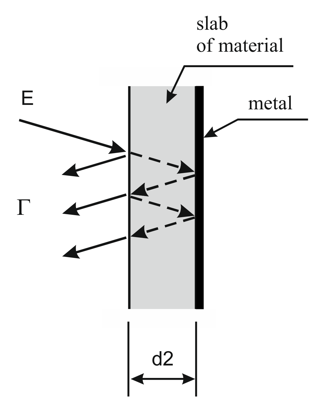
4.2. Reflection Properties of the Absorber Lying on Conductive Sheet
The reflectivity of the absorber is an important parameter. This property can be analyzed in a free-space condition or in the case of when a slab of material is backed by a metal layer. Each of these cases yields slightly different interpretations. Based on the commonly presented models in the literature, the second case is analyzed in this work. To assess the reflection properties of the proposed absorbing material, the configuration of a slab of material on the metal layer was taken into consideration, as presented in
Figure 4 where a schematic diagram of propagating rays is presented.
Taking into account multiple scattering propagation inside the slab, the reflection coefficient Г is the vectorial sum of primary reflected rays at the surface of the “air/absorber” material as well as all rays reflected at the “absorber/metal”.
The reflection coefficient of the material backed with metal can be determined using scattering coefficients.
where
S11 and
S21 are scattering coefficients for the slab of materials in free space, calculated using Equations (3)–(6).
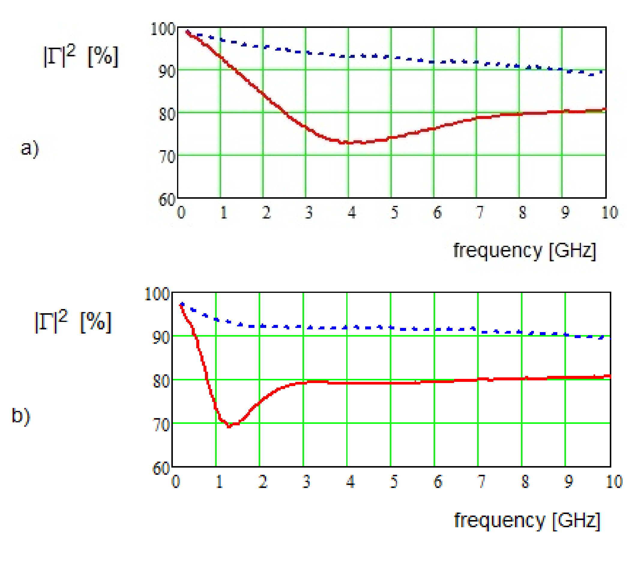
The reflectance of reduced graphene oxide and graphite was analyzed for two material layers (
d2—see
Figure 4), i.e., 2 mm and 5 mm. Reflection coefficients of these two thicknesses in function of frequency is presented in
Figure 5. In these Figures, the diagrams present the percentage of the total reflected energy (|Г|
2 (%)) in reference to the incident power density.
Charts presented in
Figure 5 show the percentage of the total reflected energy. Diagrams were presented in linear scale enabling an easier comparison with the incident power density. The presented reflection coefficients are the resultant values of reflections from material and metal layers as well as the absorption property of this material. The measurement, carried out in a frequency range from 100 MHz to 10 GHz, shows strong reflecting properties of graphite, confirming high reflectance since it reflects more than 90% energy. Thus, their applicability for EMC applications with such simple geometrical form can be questioned. To solve the problem of graphite’s high reflectivity in anechoic chambers, a pyramidal shape of graphite was applied. However, in this attempt the absorber’s volume was too large, preventing it from being used as an internal and external electronic protection.
The reflection coefficient for RGO shows significantly lower reflectance. For such material on a perfect conducting layer, the reflection coefficient of power density is about 80%. For some frequencies, this parameter is even better and achieves a value of 70%. However, this effect is not due to the absorbing properties of the material but rather due to the phenomenon of the half-wavelength distance. In this case, the reflected wave that forms the front surface of the material interferes with waves reflected from the metal layer with opposite phases. Such decreasing reflectivity could be favorable for shielding performance, but it is rather narrowband because it depends on the thickness of the slab of the absorber. It should also be noticed that such a favorable interference occurs for a normal incident field. When electromagnetic wave incidents with an angle different than 90°, the difference of phases, due to longer paths of rays inside the slab, does not meet the requirement of half-wavelength shifting.
In
Figure 5, the graphite and RGO reflectance was presented for two material slab thicknesses, i.e., 2 mm and 5 mm. The reflection coefficient of power density of graphite is rather stable over the frequency and the half-wavelength effect is not observed. In this case, reflected energy is so high that rays reflected at metal cannot interfere due to too low amplitudes. On the other hand, in reduced graphene oxide the half-wavelength effect significantly reduces the reflectivity. For a thin RGO layer of 2 mm (
Figure 5a), the half-wavelength effect significantly improves the reflectivity in broad frequency range, but in lower frequencies (lower than 1 GHz), the reflection coefficient is high. In this case, due to a thin layer, the absorbing ability is too low, and the rays reflected from metal have similar phases and do not reduce the resultant reflected field. For low frequencies, the RGO slab of thickness of 5 mm is recommended.
5. Conclusions
This work presents the investigation of graphite and reduced graphene oxide reflectance. These materials can be used to protect electronic circuits against external as well as internal reflected radiation. The main inspiration was to find a better microwave absorber material than graphite. Graphite, due to the high electric constant, is a good absorber, however, it significantly suffers from excessive reflectivity. The measurement of RGO, as a prospective form of carbon, has shown lower reflectivity performance. Graphite and reduced graphene oxide were investigated in the pure forms without any additives, such as polystyrene foam, resin, wax, etc. The measurement was implemented in a coaxial line, in the microwave frequency range from 100 MHz to 10 GHz. The measurement confirmed the well-known information that the reflection coefficient of power density of graphite lying on metal sheet reaches a high level of over 90%, while such a slab of RGO reflects only 80%. In addition, due to the half-wavelength effect on the reflection, the coefficient is reduced to 70%.
The measurement of constant electromagnetic parameters, such as permittivity and permeability, was carried out for pure materials, which facilitates the future investigation of reflectance after the addition of improving supplementing components.


