Article

Comparative Design and Performance Analysis of 10 kW Rare-Earth and Non-Rare Earth Flux Reversal Wind Generators

by
Manne Bharathi
1,*,
Udochukwu Bola Akuru
2,* and
Malligunta Kiran Kumar
1
1
Electrical and Electronic Engineering, Koneru Lakshmaiah Educational Foundation, Guntur 522502, India
2
Department of Electrical Engineering, Tshwane University of Technology, Pretoria 0183, South Africa
*
Authors to whom correspondence should be addressed.
Energies 2022, 15(2), 636; https://doi.org/10.3390/en15020636
Submission received: 23 December 2021 / Revised: 12 January 2022 / Accepted: 13 January 2022 / Published: 17 January 2022

Abstract

:
Generators are a key technological element of the wind energy generation system. Currently, there is an increasing interest in adopting non-conventional stator-mounted permanent magnet generators, e.g., flux reversal generators (FRGs), which is a good alternative to conventional synchronous generators for medium-speed wind turbine generator applications. The usage of FRG with rare-earth (RE) permanent magnets (PMs) is increasing due to their high efficiency and high power density factors. However, RE PMs are unattractive to wind generators in terms of their cost and unpredictable market supply. In this paper, an attempt is made to study the potential of FRG with non-rare earths (ferrite PMs) for wind generators. The three-phase, 6/8 pole FRG is designed and compared with RE and NRE PMs for wind generator application at 375 r/min, 10 kW. Using 2D FEA, both the generators are compared in terms of their power generating performance with excellent overload capability. It shows that the average efficiency of the generators is approximately similar, but the torque density of NRE-FRG is only 51% that of RE-FRG. The NRE-FRG design is heavier, with the total active mass being 2.6 times higher than the RE-FRG, but with the estimated total active material cost of both generators almost the same. Moreover, the toque ripple for RE-FRG is 64% higher than for NRE-FRG. The demagnetization risk analysis was performed, and it is found that at higher temperatures, RE-FRG structures are prone to higher demagnetization risks, while it is much lower in NRE-FRGs. In summary, it is found that NRE-FRG is a suitable alternative to RE-FRG for medium-speed wind turbine generator applications in the 10-kW power range.

1. Introduction

Generators are a key technological element of the wind energy generation system. Recently, there has been an increasing growth and prominence of wind energy generation development, which has dominated the overall renewable power generating capacity and is considered one of the fastest growing renewable energy sources with an installed capacity of 651 GW by the end of 2020 [1]. This encourages researchers’ interest in designing and manufacturing wind generators for various power levels [2]. Wind energy generators acquire various types of AC generators, such as induction generators, permanent magnet synchronous generators (PMSG), and non-conventional stator PM generators. Permanent magnet synchronous generators (PMSG) with permanent magnets on the rotor are attractive for high power wind energy generation applications because of their high energy yield compared to other induction and electrical-electrical synchronous generators [3].
Stator-mounted PM machines have been recently experimented for wind generator applications [4,5]. With a simple and robust rotor, these machine variants provide ease of cooling since active parts are stator mounted, as well as reduced risk of demagnetization [6]. The flux reversal machine (FRM) is a typical non-conventional stator-mounted PM machine, in which both PMs and armature windings are located on the stator, leaving the rotor simple and robust as it resembles that of the switched reluctance machine (SRM). Then, the PMs are mounted on the stator pole shoe of the FRM with potentials for high power density compared to similar PM machines [7,8,9,10].
The traditional design of FRM uses rare earth (RE) PM options such as Nd-Fe-B, N38SH, and Sm-Co. RE PMs are expensive and their supply uncertainty has forced researchers to find alternatives, e.g., non-rare earth (NRE) PMs. NRE-PMs are several times cheaper, and the resources and extraction are more mature across various countries of the world compared to RE, but they carry greater demagnetization risks due to lower coercive force [11]. Nevertheless, FRG is shown to possess unique characteristics that reduce the demagnetization risks at rated load conditions [12].
Numerous FRG structures have been proposed in the past few years for wind/generator applications. For the first time, the single phase 2/3 pole FRG with Sm-Co magnet structure was proposed as a high-speed claw-pole alternator in 1997 [13]. Then, the direct and quantitative performance comparisons are made with other competing brushless generators by using the flux-mmf diagram technique, which is superior to the generalized generator modeling techniques in this class. It was shown under experimentation that FRG possesses a unique flux nature and small inductance variation with rotor position. Based on the structure best suitable for high-speed and high-power applications, this is the most competitive among other brushless generators.
In [14], the study considered the comparison of PM FRGs based on commonly used concentrated winding as against distributed winding; the superiority of later in terms of voltage quality, with smoother and much lower total harmonic distortion, was clearly emphasized. It must be said that the PM material used for the study in [14] is based on RE technology. In [15], the simple and rugged construction of FRGs, with high power density and fault-tolerant capability, was exploited for roof-top wind and aircraft generators. To this end, a novel ring outer rotor FRG with the inner bridge is proposed to improve the power factor, voltage regulation, and flux leakages inherent in FRGs. It was conclusively shown that the inner bridge PM ring FRG, improves the average air-gap flux density and reduces cogging torque while reducing flux leakage and thereby improving the power factor compared to conventional 6/14 pole outer rotor topology.
In [16], it was explained that the high specific torque characteristics and simple rotor topology of a 2.4 kW three-phase 6/14 pole 214 r/min FRG make it suitable for low-speed direct-drive wind power generation systems, no thanks to their high number of poles. The study also compared the outer and inner rotor configurations, showing that the outer rotor FRG exhibit a higher power density of up to 1.25 times that of the inner rotor variant.
In [17], a soft magnetic composite (SMC) core material FRG is designed for gearless wind generator mode at 0.6 kW and 650 r/min. The SMC core is still RE-based, only that it is cheaper and can be easily magnetized and demagnetized. The findings from the study revealed that the active mass of the SMC FRM is reduced by 21% compared to the one whose rotor is purely contrived by steel laminations. The efficiency of the former is also improved by 7% due to reduction of the rotor losses. In [18], a novel 4-phase FRG with DC electromagnet excitation is proposed for wind power generation. When compared with a corresponding PM FRG design, the overarching advantages are that the DC design can vary its airgap flux density under varying wind resource conditions and is cheaper.
The research trend in FRG design and applications clearly shows that NRE materials are emerging. Such studies abound in other stator-mounted brushless machines [19,20]. Based on this research, ferrites (NRE) materials are appearing as suitable replacements for RE-type machines. To this end, the main motivation of this study is to expose the potential of NRE over RE PM material in FRG for geared medium-speed wind power generator applications. This is ideal for wind turbine generator designs because, just as other ferrite electrical generators, it reduces overall generator costs while also allowing easily accessible ferrite raw materials to be used for the machine’s excitation system. Furthermore, the existing literature has not highlighted the design of NRE FRG using ferrite PMs, indicating a need to investigate the performance comparison of NRE versus RE FRGs. The selection of the medium-speed range is thanks to its competitive generator performance to cost index compared to geared high-speed and gearless systems [19].
In this study, a three-phase, 6/8 pole FRG designed with RE and ferrites PM, with similar parameters and characterization for a 10-kW power scale, is investigated using finite element analysis (FEA). The proposed 10 kW power range being investigated is clearly a niche power level of lower power limit small wind turbines, the so-called micro wind power generation units [2,21,22]. Further, both machines, NRE and RE FRGs, are compared in terms of their electromagnetic operating performance such as output voltage, torque density, power factor, torque ripple, as well as efficiency at either no-load or rated conditions. Thereafter, mass and cost estimates, as well as demagnetization risk analysis of the associated PM FRG variants are studied and compared in FEA for medium-speed wind power generation.

2. Design Sizing and Analytical Formulation

The design of an electrical generator procedure is different from that of a motor. In the case of generator operating conditions, characterized by varying the external load, whereas in motor design, a predefined maximum torque point ( I d = 0 ) under AC brushless operation. Then the generator is not practicable for designing under an AC brushless operating mode, much like a motor action. Therefore, the generator performance is characterized using the co-simulation method, connecting the generator with an external load. In this regard, the generator with rare earth and ferrites PMs is designed under the same specifications with a rated output power of 10 kW and at a rated speed of 375 r/min. FRGs are modeled in direct and quadrature (dq) axis references to proclaim the steady-state. dq equations are used to analyze both the generators’ performances. Both generators’ power generating capabilities are thoroughly investigated in terms of power and torque density, overload capability, cogging torque, torque ripple, efficiency, and power factor.

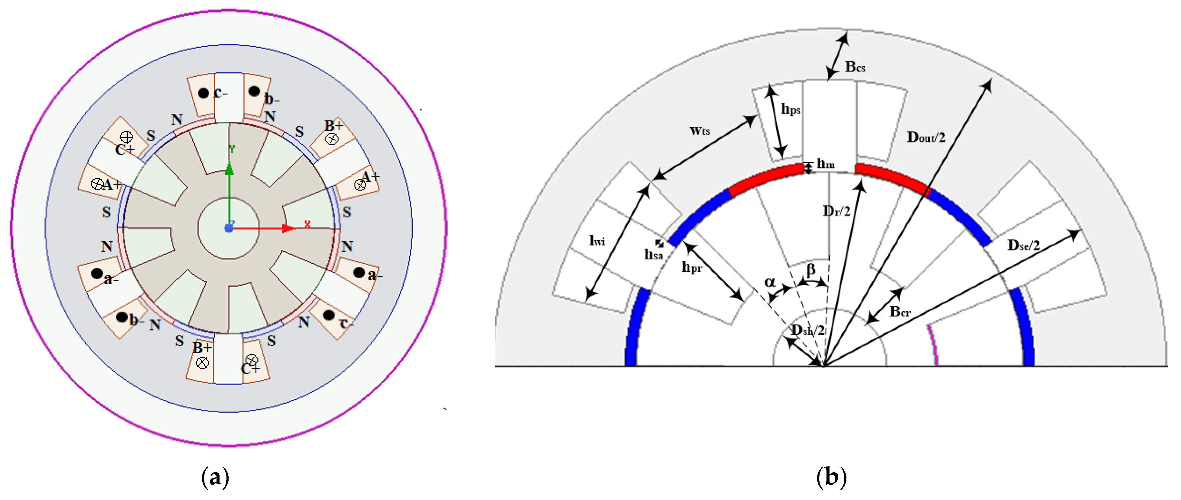
2.1. Basic Structure and FEA Model Formulation

The three-phase 6/8 pole stator-slot ( N s ) /rotor-pole ( N r ) combinations achieve symmetrical phase back electromotive force (EMF) with higher torque density. A reduced number of stator-slot/rotor pole numbers is preferred for reduced iron losses and manufacturing difficulty, whereas a lower number of poles causes a reduction in the amplitude of back-EMF [23]. Considering all the limitations, a compromise between high back EMF and standard (50 Hz) frequency operation, a 6/8 FRG structure is chosen. Based on the generator rated speed (n) and rotor poles ( N r ) , open circuit EMF frequency ( f e ) and the flux pattern speed in terms of supply frequency (nf) as expressed by
f e = n N r 60
n f = 60 f e
The two-pole pitch span angle ( τ ) resembles two PMs poles of oppositive polarities placed on the stator poles expressed as
2 τ PM = π D r N r
The main design specifications of RE-FRG and NRE-FRG with the same power level are given in Table 1. The sizing equation used to model the FRG [24] is given as
D r = 2 P b π f t λ ω r J η 3
P b = rated power, f t   = tangential force density (2.1 N / cm 2 ), λ is the ratio of stack length to rotor diameter ( D r ); ω r = rotor speed (rad/s); J = current density and η   = machine efficiency. The medium value of λ is 1.2, justified for 6 stator slots [10].
In the FRG, energy conversion occurs by virtue of the interaction between the stator coil MMF and PM fields. N s / 3 is the number of stator poles per phase with coils in series, while the induced EMF per phase ( E m ) and electromagnetic torque ( T e ) are given as [24]
E m = N s 3 . n p 2 . N t . 2 π ω r . l stack . π D r . K fringe . B PMi
  T e = 3 E m I rms 2   ( 2 π n )
where N s is number of stator slots, n p is number of PM pole pairs, N t is the number of turns per coil, l stack is stack length, K fringe is flux fringing factor, B PMi is airgap flux density and I rms is RMS value of the current.
The sub-optimal major design dimensions of FRG such as pole width ( w ts ), pole height ( h ps ), slot opening ( l wi ), and stator outer diameter ( D out ) are expressed as
w ts = λ pmmax B ps l stack
  h ps = 2 N t I rms JK fill l wi
l wi = 2 π D r N r w ts
D out = D r + 2 h m + 2 h sa + 2 h ps + 2 B cs
where λ pmmax is maximum flux per pole of the 6/8 pole FRG structure having 8 rotor poles and 8 interpoles; B ps is stator pole flux density, h m is PM thickness, h sa is stator pole shoe height, h ps is stator pole height, and B cs is stator back iron thickness. The conceived FRG design specifications and parameters are listed in Table 1, while the basic structural view of a 3-phase, 6/8 pole FRG and dimensions are shown in Figure 1. The angles subtended by the rotor pole (α) and interpoles (β) are π / 8 [23]. The interpole space is rounded off to reduce fringing near rotor back iron. In the general basic design of permanent magnet flux reversal machines, B cs and rotor back iron thickness ( B cr ) are assumed to be equal [24]. To improve the torque density and reduce the cogging torque effects in the air gap, a pseudo-optimum parametric variation of design dimensions is undertaken in FEA. Based on the design structure of RE-FRG, the NRE-FRG is designed by increasing the cross-section of the machine and stack length to get 10 kW power range. This slightly increases the size, losses, and active material mass of the NRE-FRG of machine, while maintaining other parameters to be the same as the RE-FRG.

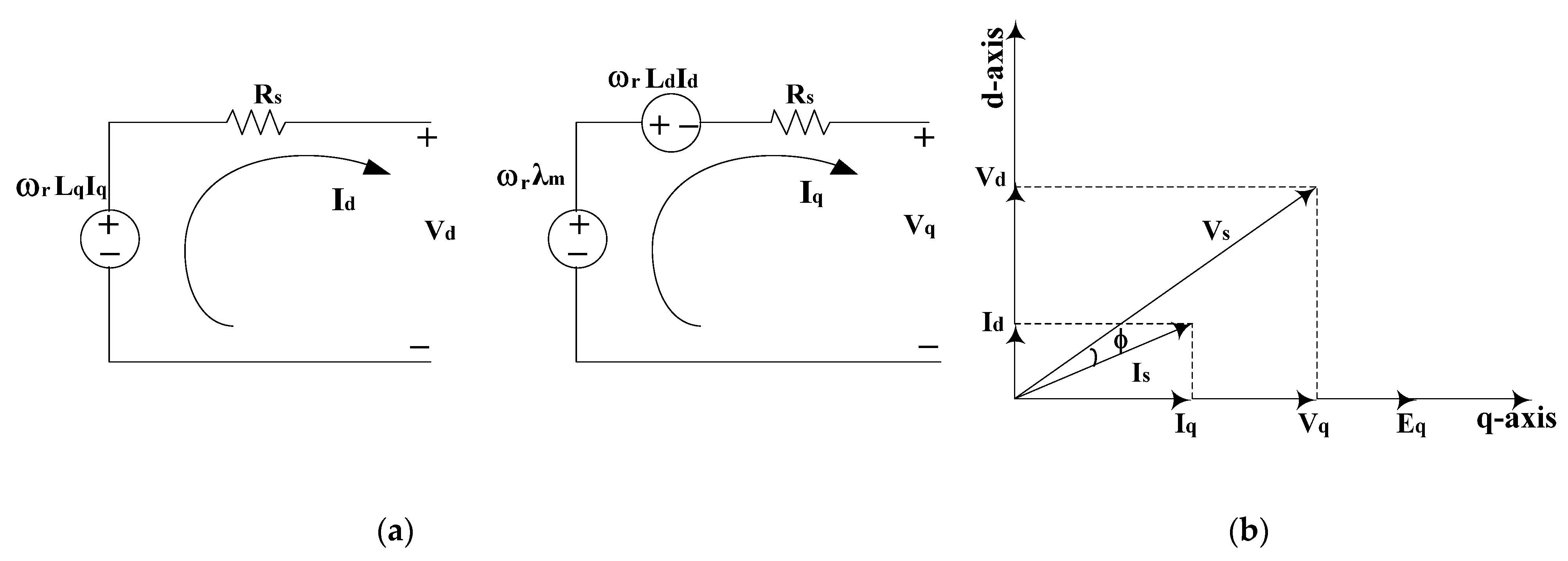
2.2. DQ-Axes Modelling

The 3-phase 6/8 FRG structure is transformed into traditional dq axes reference frames that are revolving at rotor speed. The static and steady-state behavior of the FRG is investigated using dq equivalent circuits and phasor diagrams, as shown in in Figure 2. In the case of FRG, rotor speed, and flux pattern speeds are different, not as in traditional synchronous machines, so that the rotor speed is N r times less than the flux pattern speed from (1) and (2). The variation in these speeds is represented by k. It is the ratio of rotor speed to the flux pattern speed. The generalized equation of k is as follows:
k = N r ( P eq / 2 )
where P eq is the number of effective flux pattern poles. With 6/8 pole FRG structure, k value is 8. Stator voltage and flux linkage equations under dq reference frames with positive current flowing out are expressed as
V d = R s I d + ω r L q I q
V q = R s I q ω r L d I d + ω r λ m
λ q = L q I q
λ d = L d I d + λ m
where λ m mutual flux linkage due to PMs, V d , V q , I d , I q , L d , L q , λ d , and λ q are the dq axis voltage, currents, inductances, and flux linkages, respectively.
The electromagnetic torque ( T e ) in terms of dq reference frame is expressed as
T e = 3 2 P eq 2 k ( λ m I q + I d I q ( L q L d ) )
The stator phase winding resistance is evaluated according to machine slot phase winding information expressed as [25]
R s = 4 ρ cu N t   2 ( l stack + l end ) A coil
where ρ cu is the resistivity of the copper material at room temperature, A coil is the area of the coil per phase, l end   = ( w ts + l wi ) is end winding length of the machine.
The winding copper losses of the generator at the rated condition and the core losses of the machine are estimated through FEA from the Steinmetz empirical equation as
P cu = 3 2 ( I d 2 + I q 2 ) R s
P core = K e f a B i b G
where K e is Steinmetz material coefficient, a is the exponent of machine electrical frequency, b is the exponent of peak airgap flux density, and G is the mass of the laminated material.
The output power ( P o ), efficiency ( η ), power factor (PF), and torque density ( T d ) of the FRGs, while ignoring friction and windage losses are expressed as
P o = 1.5 ( V q I q + V d I d )
η = ( P o P o + P core + P cu ) 100 %
PF = ( V q I q + V d I d ) ( ( V q 2 + V d 2 ) ( I q 2 + I d 2 ) )
T d = 4 T avg π D out 2 l stk
The torque ripple factor at load condition is expressed as
K rp = ( T max T min T avg ) 100 %
where T avg is average load torque, T max , T min is maximum and minimum instantaneous torque values at load condition.
The mass (M) of various parts of the generators are estimated by
M = ( o l stack A   dz ) D
where A is the surface area the object, D is the density of the material.
The temperature dependence of demagnetization coefficients is modeled by
B ri ( T ) = B r , 20 C ( 1 + C 1 ( T 20 0 ) )
H cj ( T ) = H c , 20 C ( 1 + C 2 ( T 20 0 ) )
where B ri and H cj are induction and coercive forces, C 1 and C 2 are the temperature coefficients of B ri and H cj , respectively, and T is the temperature on the object.

3. Generators Performance Evaluation

Many researchers have studied and developed various FRG structures for wind generator applications. Most of the designs are low power scale with RE type FRG structures [15,16,17,18]. Here, in this study, a 6/8 pole, 10 kW RE-FRG, and NRE-FRG are designed and implemented in 2D FEA ANSYS Maxwell for medium-speed wind turbine generators. Both the generators are designed with a rated speed of 375 r/min and have similar dimensional parameters. The power density, torque density, efficiency, and power factor of the generators are analyzed and compared, mostly in dq reference frame. Therefore, in this study, the analysis part is divided into four subsections, where in the first sub-section, transient no-load analysis is carried out to study the flux linkages, induced voltages, and cogging torques for both the machines. Thereafter, in the second sub-section, on-load transient analysis is conducted to further study the electromagnetic performances of both machines. In the third sub-section, a comparative analysis of mass and cost estimation of both machines is undertaken. Finally, in the fourth sub-section, the investigation and comparison of the demagnetization risks are undertaken by setting the temperatures under rated load conditions for both the generators, while the flux density variations under different temperatures are observed.

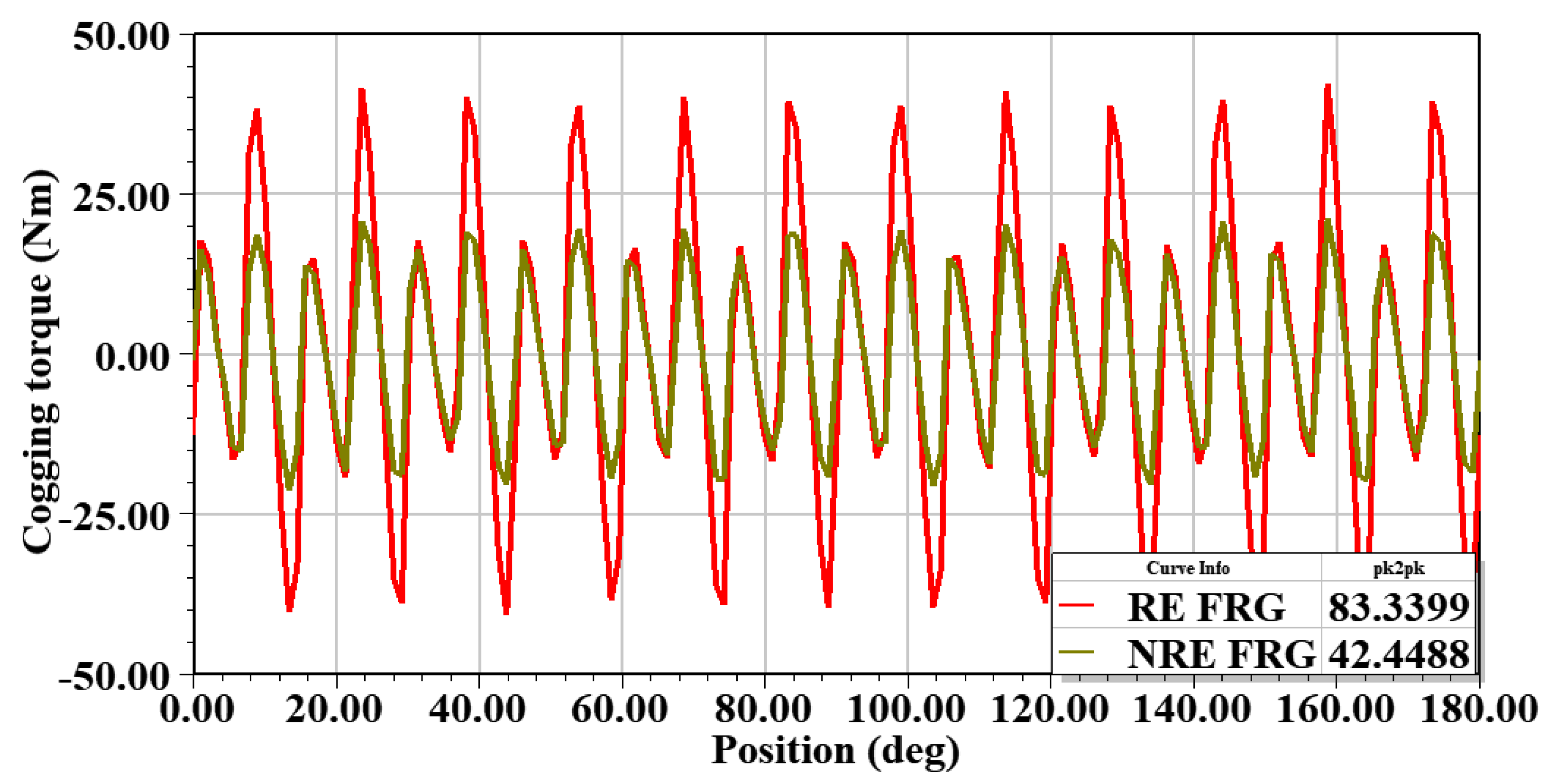
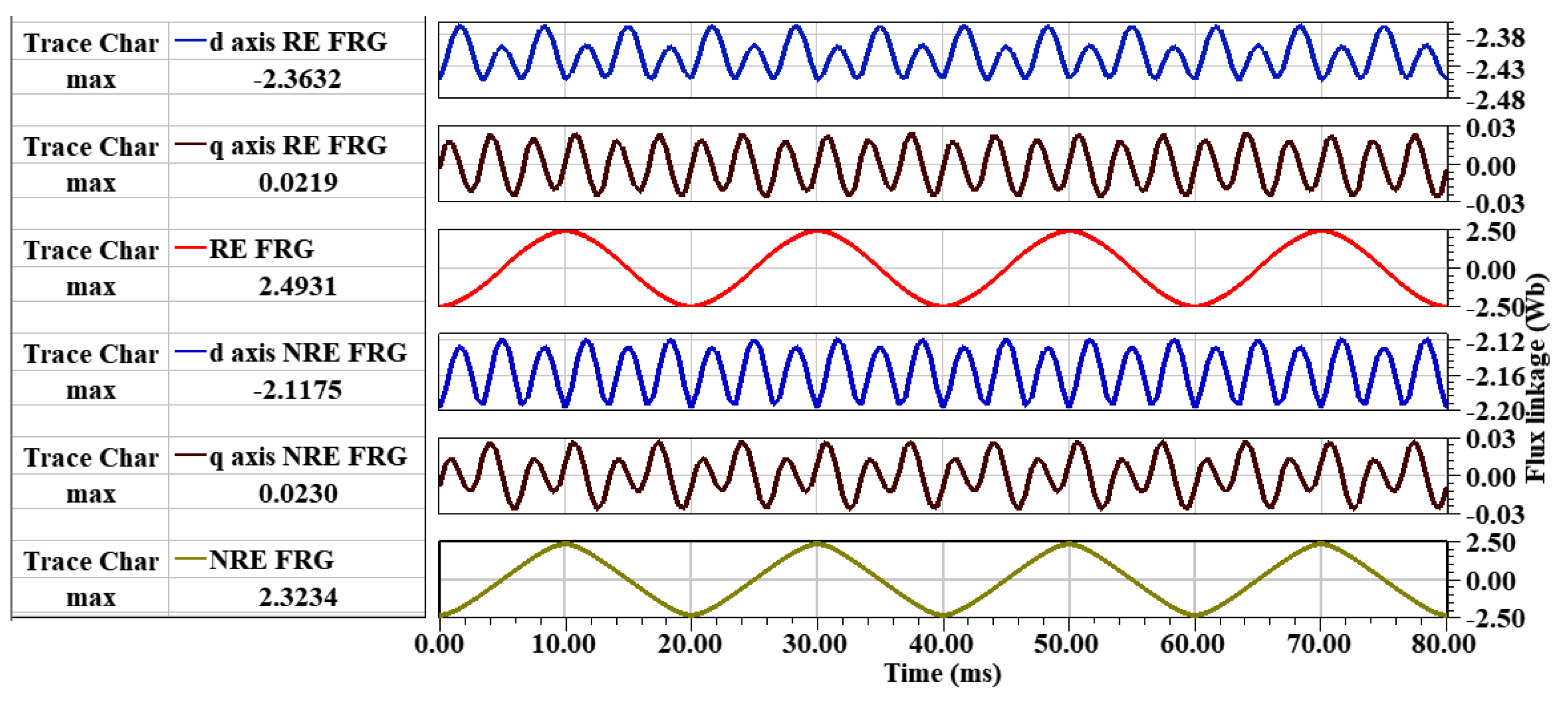
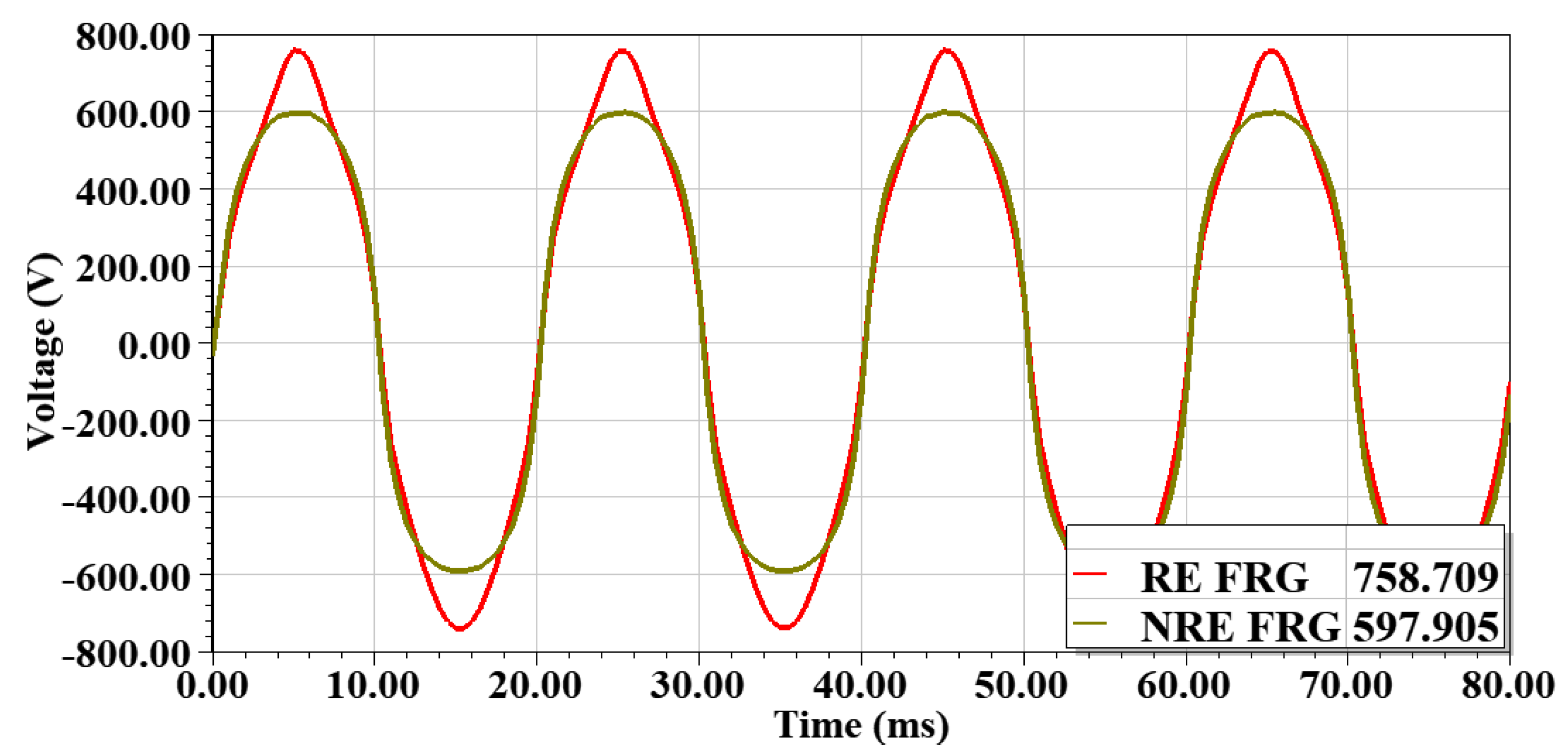
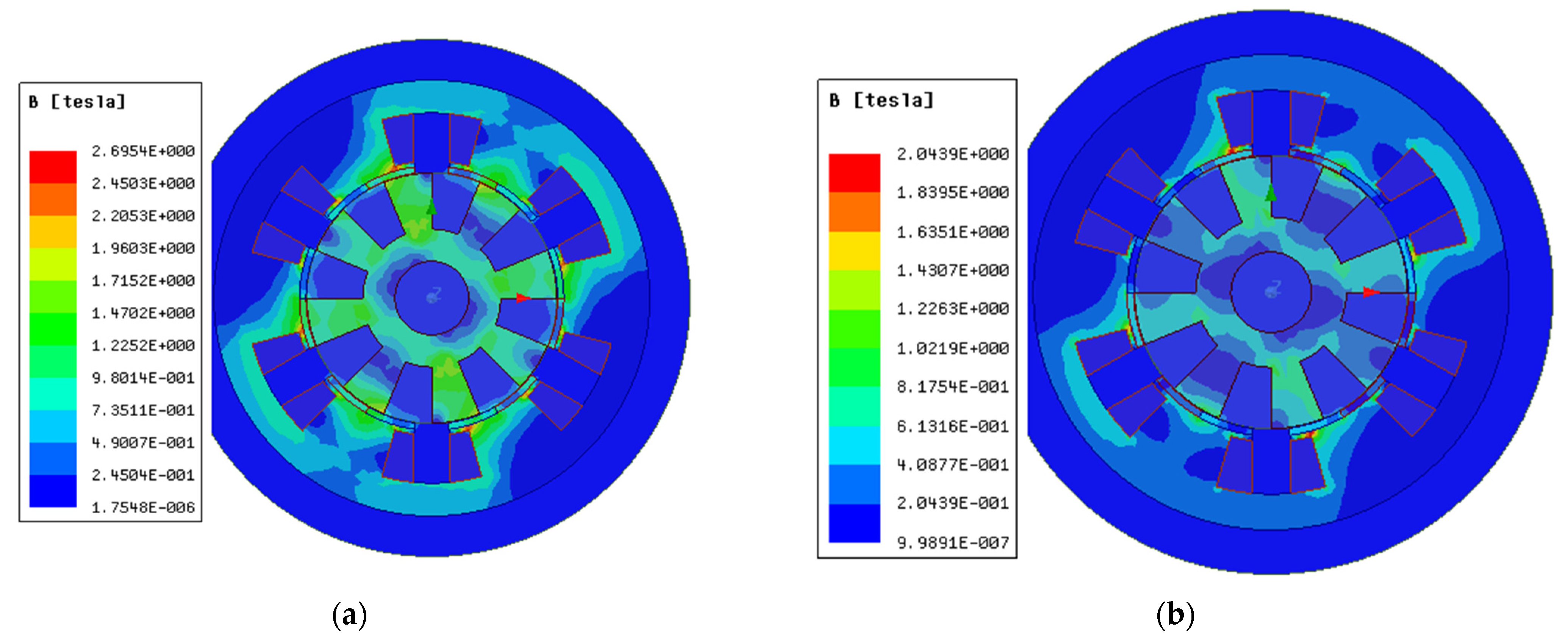
3.1. No-Load Analysis

In this section, the RE-FRG and NRE-FRG machines are under open-circuit conditions based on 2D FEA. Under no-load conditions, phase flux linkages, back EMF, and cogging torque are obtained. In static analysis, when no-load is applied to the armature winding, the EMF induced at the open winding terminals are compared in both machines. From Figure 3 and Figure 4, the open circuit analysis reveals that the phase flux linkages and fundamental EMF magnitude of the NRE-FRG structure are lower than for the RE-FRG because the remanence flux density and coercive forces of the ferrite PMs are much lower.
Under no-load, both machines exhibit cogging torque, which results in acoustic noise and vibration. The peak-to-peak cogging torque is thus evaluated for both the generators. From Figure 5, it is revealed that the peak-to-peak cogging torque of RE-FRG is twice that of the NRE-FRG because it has higher coercive force, reducing the cogging torque of RE-FRG [26,27]. The cogging torque characteristics should invariably impact the pulsation in the instantaneous torque.

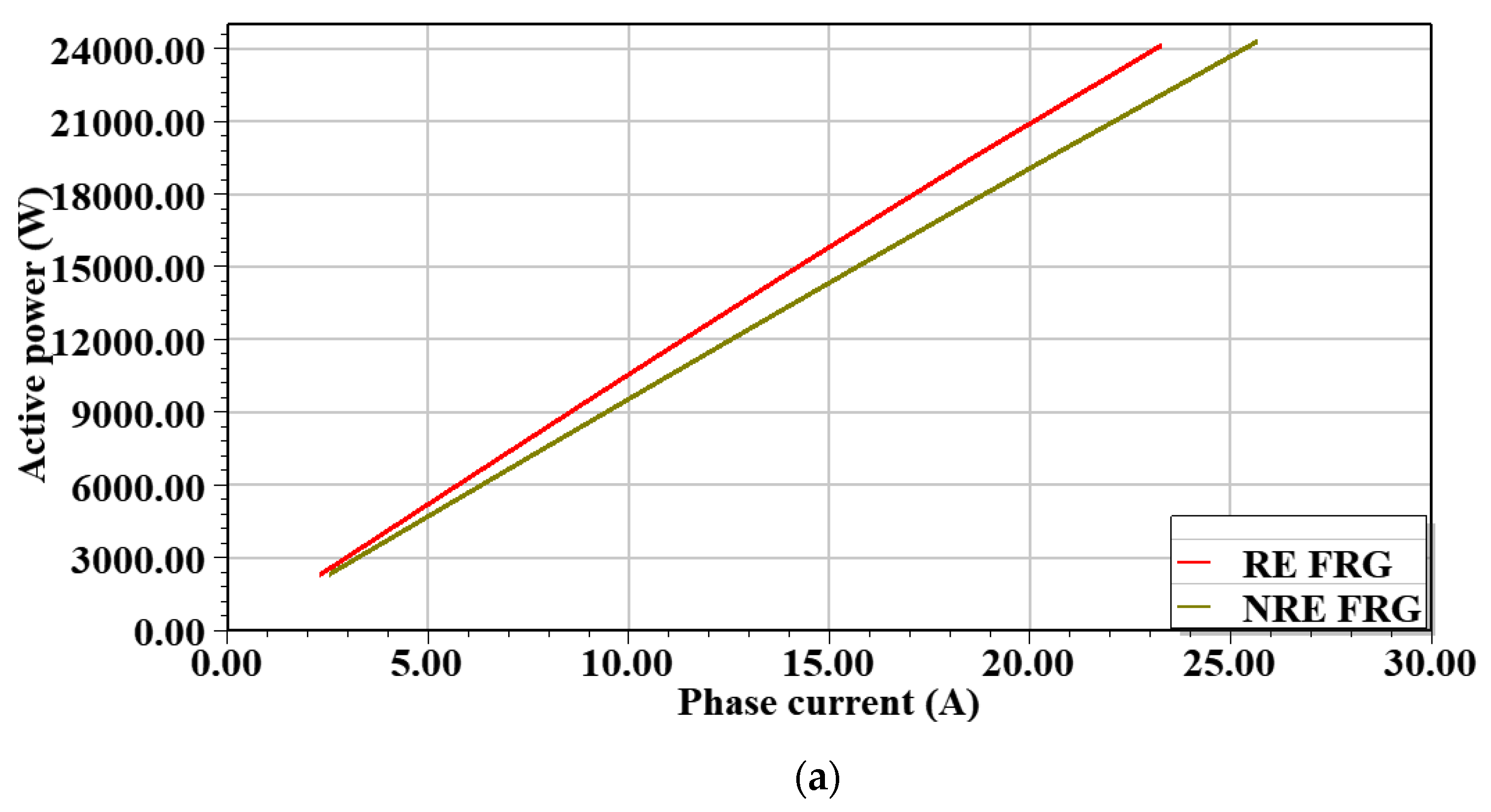
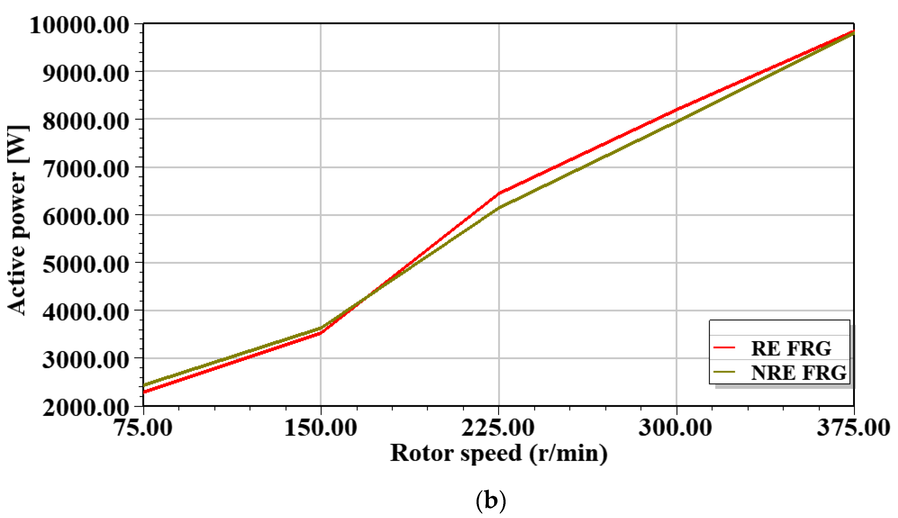
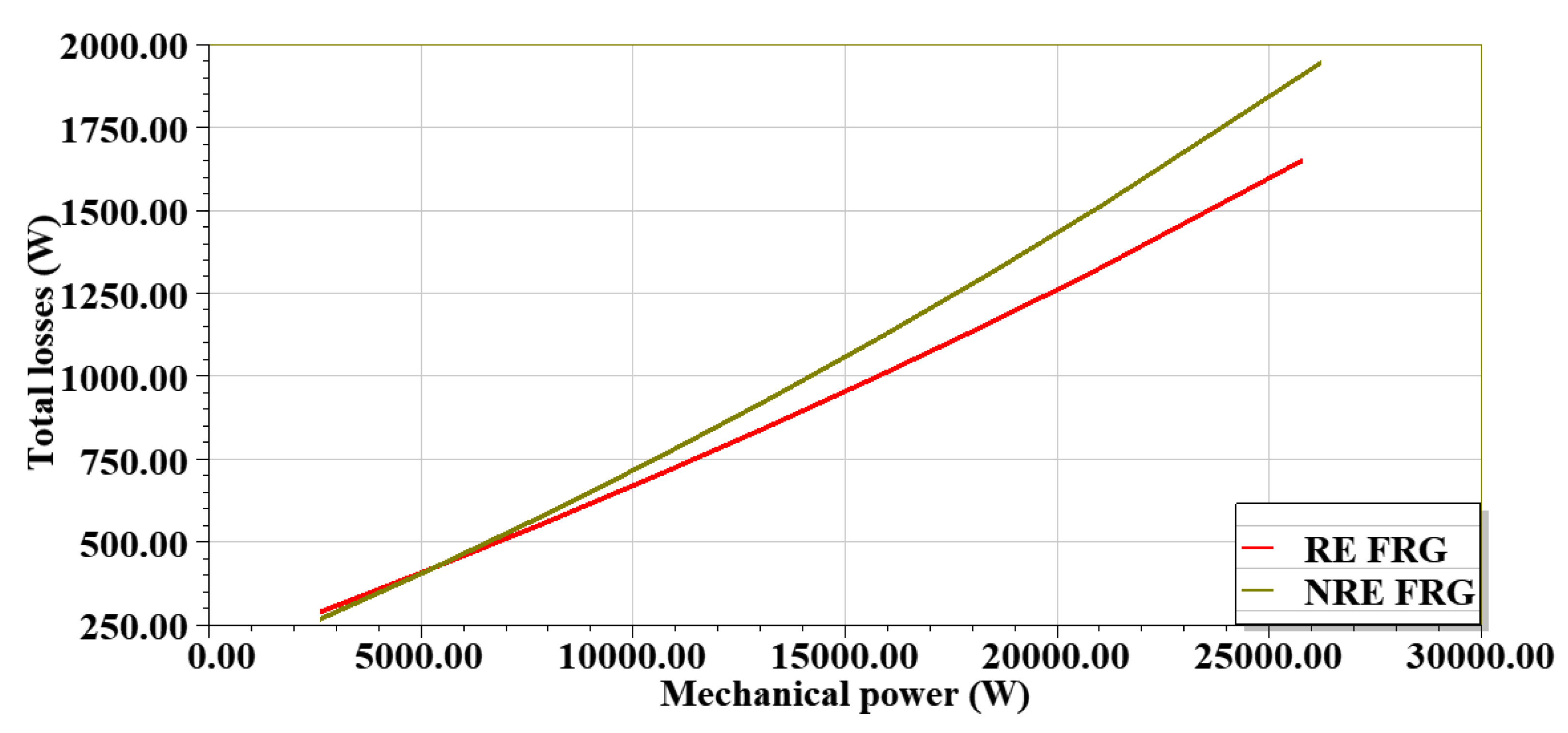
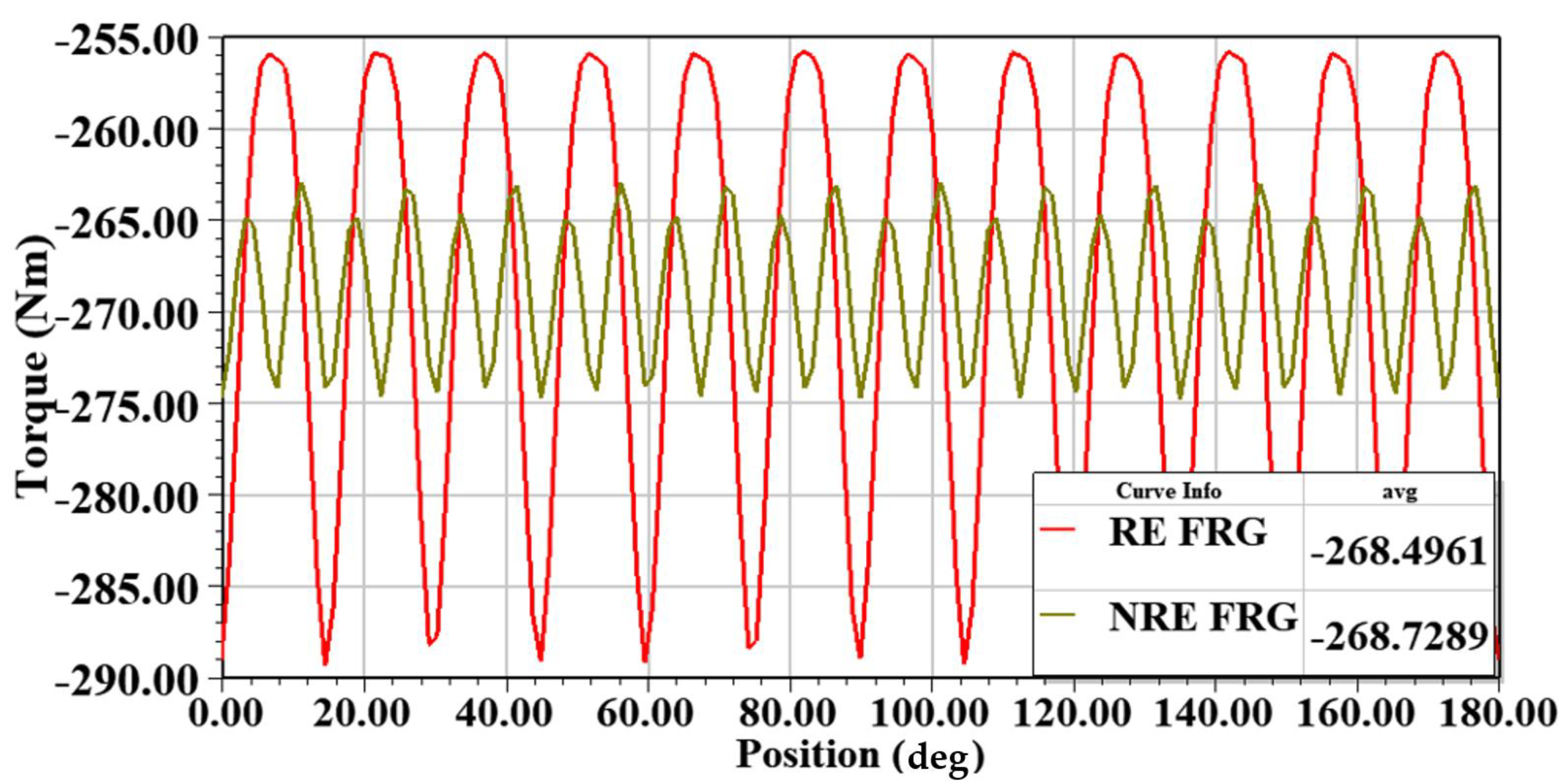
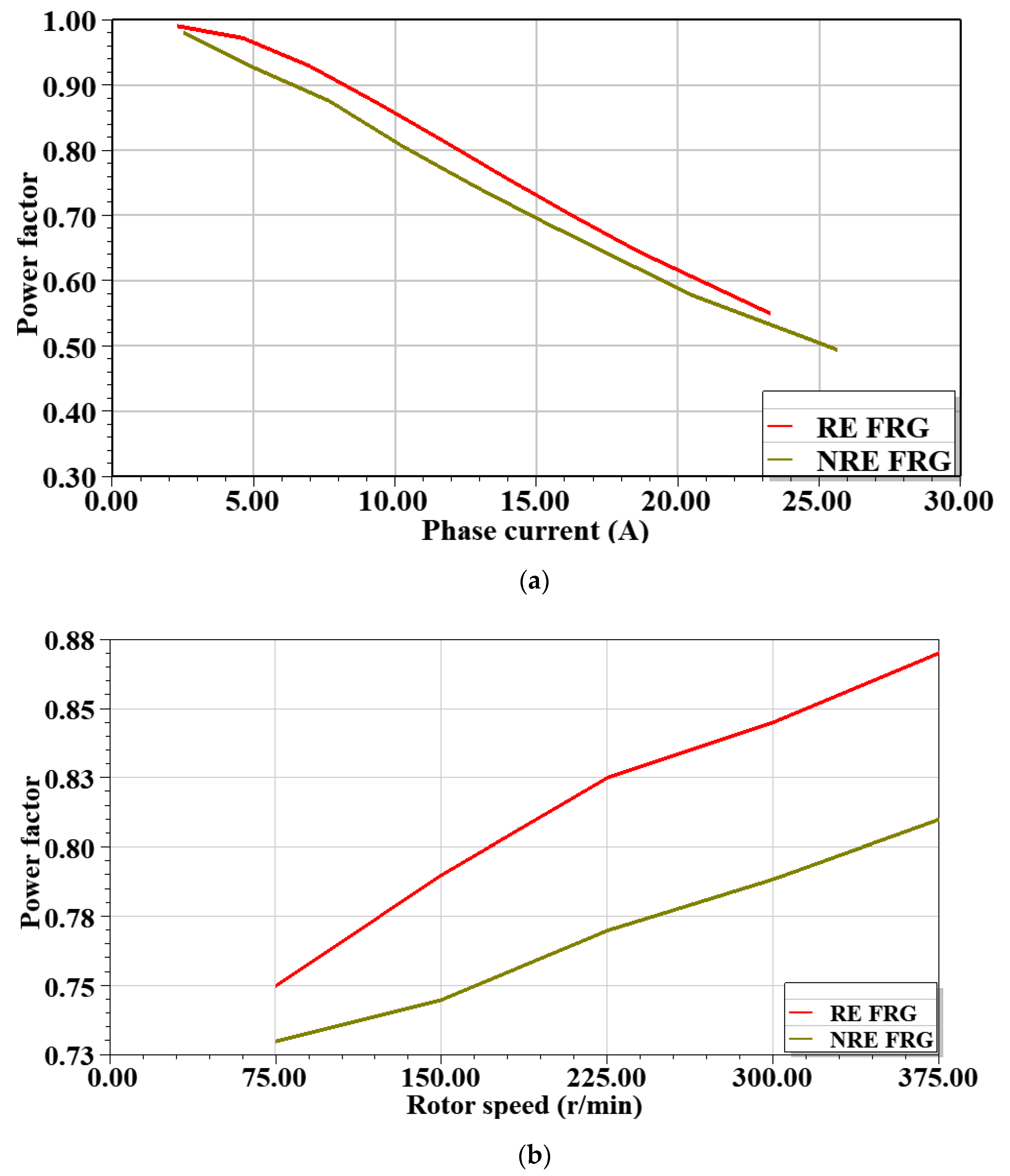
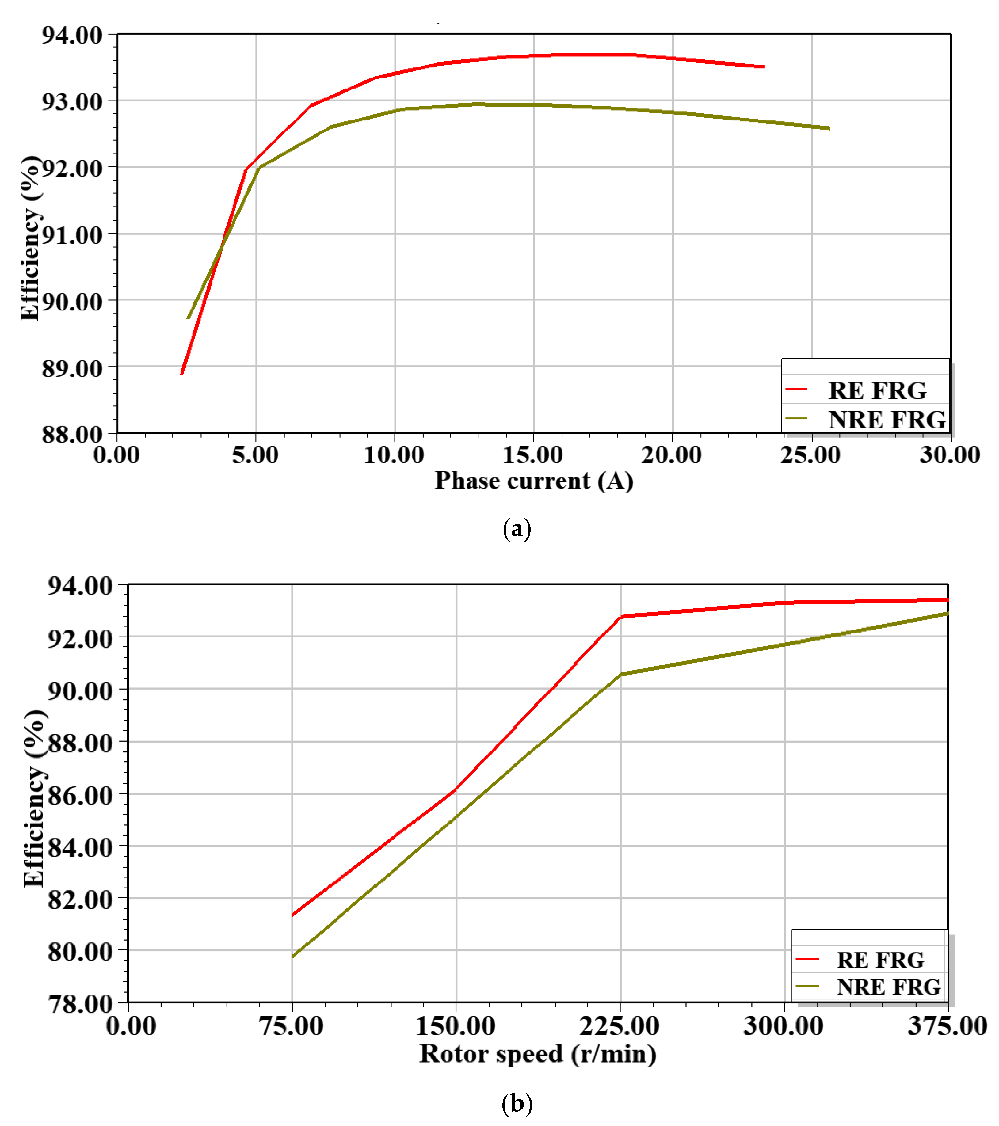
3.2. On-Load Analysis

On-load power generating performances include torque ripple, efficiency, losses, power factor, and power density of the RE-FRG and NRE-FRG. In the first case, both generators are operated at 375 rpm under varying load current in 2D FEA, while in the second case, the load current is fixed at rated while generator speed is varied. Hence, based on the rated voltage of each phase, rated power, and impedance triangle, the calculated rated load is 63 + j34 Ω. Figure 6 shows the flux density plot of RE-FRG and NRE-FRG under rated load conditions. The generator load profile is demonstrated by varying the phase current against the real output power for both the generators, analyzed up to 2.5 times the rated load as presented in Figure 7a. In all cases under load analysis, the wind generators are pushed up to 250% of their rated load to exhibit their overload profile. In Figure 7b, the output is now compared at varying generator speeds. The active power of RE-FRG is somewhat higher than that of NRE-FRG for a wide range operating point, with a linear profile conceived up to 2.5 pu in Figure 7a, demonstrating that both generators are designed with excellent overload capability. Overall, the performance comparison analysis of RE-FRG and NRE-FRG under 2D FEA is summarized in Table 2.
The phase currents versus efficiency variation of RE-FRG and NRE-FRG are presented in Figure 8a, while the generator speed is varied with efficiency in Figure 8b. The efficiency of RE-FRG is seen to be generally higher in both figures. The losses in the generators considered are stator core loss and winding loss (of armature winding) excluding windage loss and fiction losses (mechanical losses). Total losses of NRE-FRG are higher than RE-FRG by 7% at rated condition due to increased copper losses. Electromechanical power versus total loss variations are investigated in Figure 9. Torque ripple at rated load of both generators is analyzed and evaluated based on (24) and is shown in Figure 10; it is discovered that RE-FRG has 64.7% higher torque ripple compared to NRE-FRG. The power factor load curve is demonstrated in Figure 11a by varying the phase current against power factor for both the generators up to 2.5 times of rated load, while the generator speed is varied against power factor in Figure 11b. The full load power factor of NRE-FRG and RE-FRG are evaluated as 0.81 and 0.87, respectively. The RE-FRG always exhibit superior power factor quality compared to the NRE-FRG in both figures, indicating higher cost premium on power electronic converter costs for the latter.

3.3. Mass and Cost Estimation

Mass and cost estimation are two key parameters for wind generators. The mass calculation of each active material used for the generator can be evaluated using field calculus as in (25). An estimation of the surface area of each object, such as rotors, stators, magnets, etc., is undertaken for both machines. Thereafter, it is multiplied with axial length ( l stk ) and respective material mass density of each object, as well as evaluation of mass of the required material stated in Equation (26). Finally, the total cost is estimated by multiplying the weight by its corresponding material unit rate. From an economic standpoint, the total PM cost of ferrites is approximately seven times lower than rare earth, based on quotations in Table 3 [28]. At a closer look, it is observed that NRE-FRG requires at least two times the total active mass and 2.7 times (ferrite PM thickness is a little bit high) of the PM mass of RE-FRG in Table 4. Because of the higher market price of RE PMs, the cost of NRE-FRG is almost the same as that of RE-FRG. Based on (23), the torque density of the RE-FRG design is seen to be 1.96 times higher than NRE-FRG as indicated in Table 4.

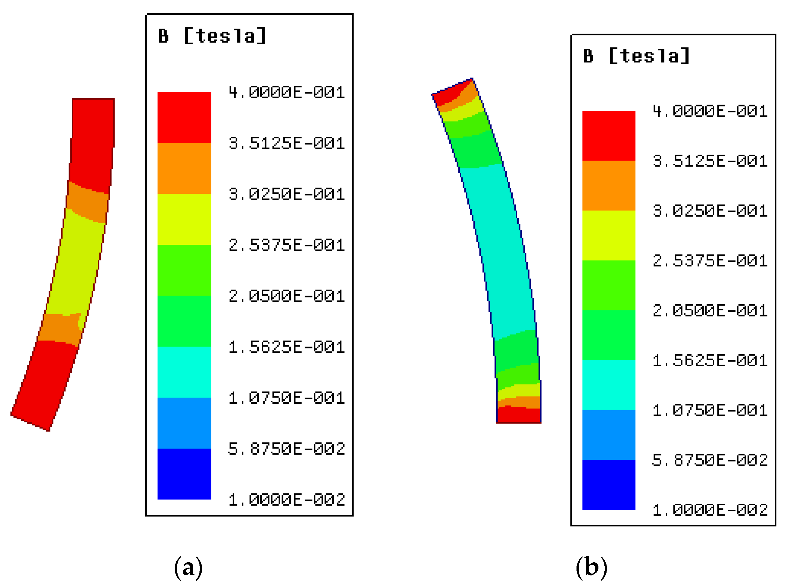
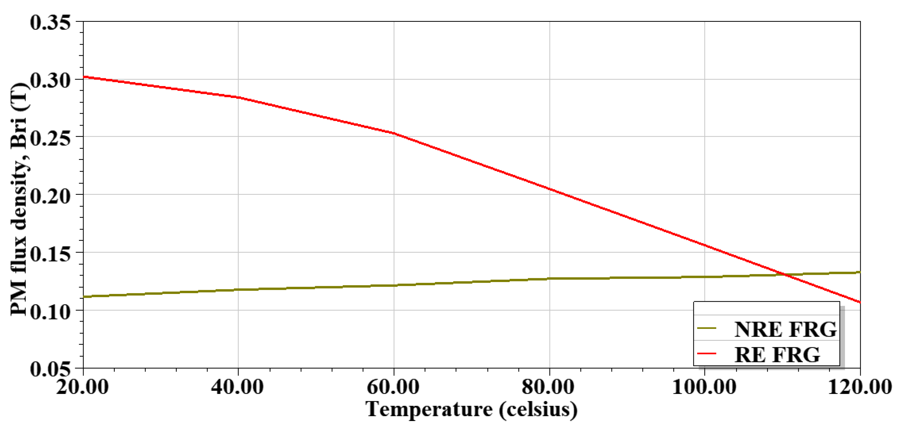
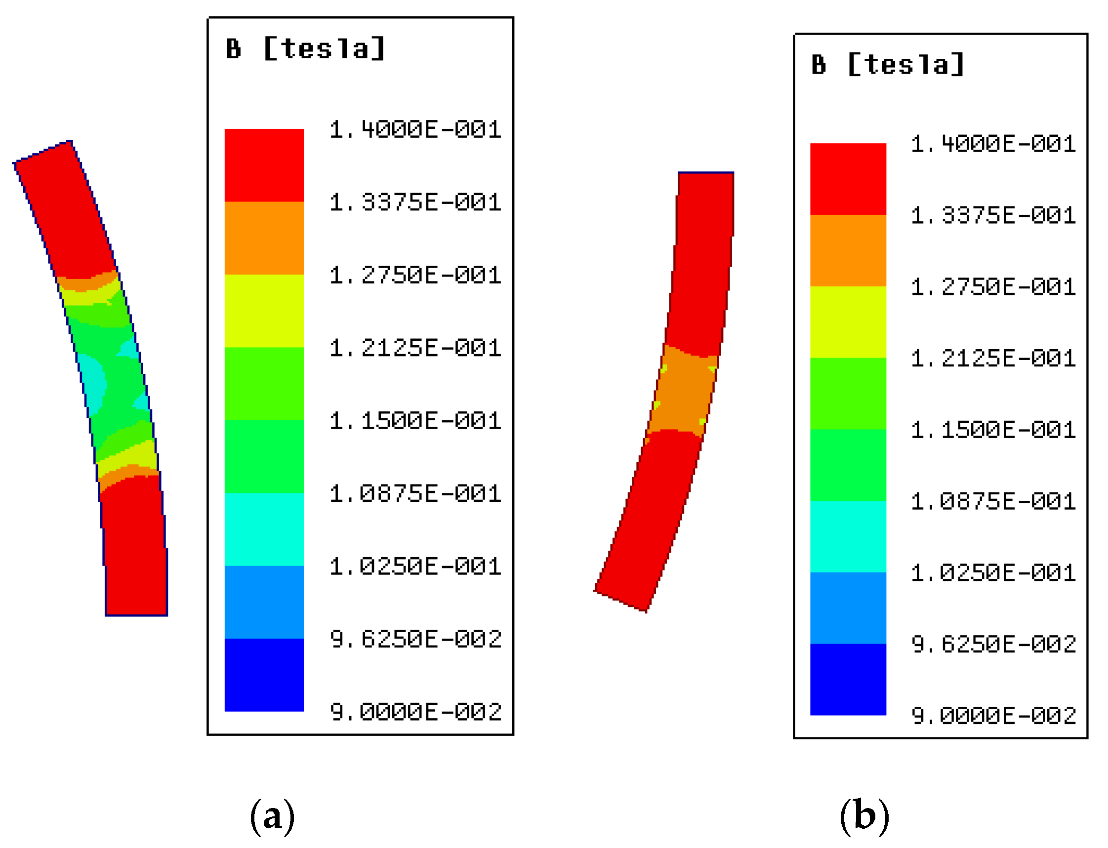
3.4. Demagnetization Risks

Demagnetization can weaken the magnetic properties of the magnet at high temperatures and lead to a reduction in the performance of the generator. A general characteristic of PM and their demagnetization susceptibility is that they are inversely related to the absolute temperature or extreme currents in the winding. The coercivity ( H c ) of typical (rare earth) PMs is generally negative temperature coefficients, but this generalization does not apply to ferrites PMs due to their positive temperature coefficients [29].
In the PMs, the minimum radial flux density position is to be considered as a demagnetization point for a given FEA solution for both the generators. Investigating the RE-FRG and NRE-FRG designs, the demagnetization withstand capability to appraise the impact of temperature rise on the remanence of the PM materials is undertaken by using 2D FEA, in ANSYS Maxwell. Here, the RE-FRG design, Nd-Fe-B type PMs are employed, which is under the grade of N35SH, and its remanence flux density is 1.2T. Demagnetization occurs below 0.25 T. Then, for NRE-FRG, Sr-Fe type PMs are used, with a grade of Y32, and the remanence flux density is 0.4 T, then the demagnetization knee point occurs below 0.1 T [30,31]. In this sub-section, an investigation on the demagnetizing risks is done by varying from minimum room temperature ( 20   C ) to a high temperature (1 20   C ) and then analyzing the corresponding impact on radial PM flux density ( B r i ) and power factor. Temperature coefficients, residual induction ( C 1 ), and residual coercive force ( C 2 ) are taken from respected grades of PMs used for RE-FRG and NRE-FRG designs as indicated in Table 5 based on (26) and (27).
The radial flux density of PMs is examined for RE-FRG when it becomes lower than 0.25 T ( B ri > 0.25 ) and for NRE-FRG when it becomes lower than 0.1 T ( B ri > 0.1 ), both at a maximum temperature of 120   C . Figure 12, based on the evaluated profile, shows the RE-FRG is unable to satisfy the safety limits at the temperatures above 60   C . However, for NRE-FRG, it satisfies its demagnetization safety limits and the performance is good at above room temperature. PMs demagnetization points at 20   C and 120   C for both RE-FRG and NRE-FRG with their power factor values are depicted in Figure 13 and Figure 14, respectively. Overall, it can be said that the NRE-FRG design structure performance is better at high temperatures than with RE-FRG for 10 kW, which translates to minimum demagnetization risks for the former. Hence, deep demagnetization risk occurs for the RE-FRG above 60   C with the power factor worsening at 120   C.

4. Conclusions

In this paper, two three-phase, 6/8 pole FRG structures (designed with rare earth and ferrite PMs) were analyzed and compared in 2D FEA for wind turbine generator applications, at 375 r/min and 10 kW power levels. Detailed analyses are performed under no-load and on-load power generating performances. Based on the similar performance requirements, the average efficiencies of both the machines are approximately similar, with excellent overload capability. The average torque ripple for RE-FRG under load is 64.7% higher compared to the NRE-FRG. However, the torque density of the NRE-FRG is only about 51% that of the RE-FRG, at approximately the same cost since the former is 2.6 times heavier. It is also found that for the RE-FRG design, a higher demagnetization risk occurs at higher temperatures, thereby reducing the power factor values and lowering the performance of the generator. Unlike RE-FRG, the NRE-FRG design has a lower demagnetization risk while operating at higher temperatures. Overall, the NRE-FRG structure is shown as an attractive alternative to the RE-FRG for micro kW medium-speed wind turbine generator applications.

Author Contributions

Conceptualization, U.B.A. and M.B.; methodology, M.B. and U.B.A.; software, M.B.; validation, M.B. and U.B.A.; formal analysis, M.B. and U.B.A.; investigation, M.B.; resources, M.K.K.; data curation, M.B.; writing—original draft preparation, M.B. and U.B.A.; writing—review and editing, M.B., U.B.A. and M.K.K.; visualization, M.B.; supervision, U.B.A. and M.K.K.; project administration, M.B. and M.K.K.; funding acquisition, U.B.A. All authors have read and agreed to the published version of the manuscript.

Funding

This research received no external funding, but the APC is funded by Tshwane University of Technology, South Africa.

Institutional Review Board Statement

Not applicable.

Informed Consent Statement

Not applicable.

Data Availability Statement

The data supporting this study is archived with the first author, M.B.

Conflicts of Interest

The authors declare no conflict of interest.

References

  1. REN 21. Renewables 2020 Global Status Report (Paris: REN21 Secretariat). Available online: http://www.ren21.net/gsr (accessed on 10 October 2020).
  2. Potgieter, J.H.J.; Kamper, M.J. Double PM-Rotor, Toothed, Toroidal-Winding Wind Generator: A Comparison with Conventional Winding Direct-Drive PM Wind Generators Over a Wide Power Range. IEEE Trans. Ind. Appl. 2016, 52, 2881–2891. [Google Scholar] [CrossRef]
  3. Polinder, H.; van der Pijl, F.F.A.; de Vilder, G.J.; Tavner, P. Comparison of direct-drive and geared generator concepts for wind turbines. IEEE Trans. Energy Convers. 2006, 21, 725–733. [Google Scholar] [CrossRef] [Green Version]
  4. Ojeda, J.; Simoes, M.G.; Li, G.; Gabsi, M. Design of a flux-switching electrical generator for wind turbine systems. IEEE Trans. Ind. Appl. 2012, 48, 1808–1816. [Google Scholar] [CrossRef]
  5. Akuru, U.B.; Kamper, M.J. Optimisation and Design Comparison of 10 kW and 3 MW PM Flux Switching Machines for Geared Medium-Speed Wind Power Generators. Electr. Eng. 2018, 100, 2509–2525. [Google Scholar] [CrossRef]
  6. Shao, L.; Hua, W.; Soulard, J.; Zhu, Z.; Wu, Z.; Cheng, M. Electromagnetic Performance Comparison Between 12-Phase Switched Flux and Surface-Mounted PM Machines for Direct-Drive Wind Power Generation. IEEE Trans. Ind. Appl. 2020, 56, 1408–1422. [Google Scholar] [CrossRef]
  7. Zhao, Y.; Kou, B.; Zhao, X. A Study of Torque Characteristics of a Novel Flux Reversal Machine. In Proceedings of the 22nd International Conference on Electrical Machines and Systems (ICEMS), Harbin, China, 11–14 August 2019; pp. 1–5. [Google Scholar]
  8. Gao, Y.; Qu, R.; Li, D.; Li, J. Torque Performance Analysis of Three-Phase Flux Reversal Machines. IEEE Trans. Ind. Appl. 2017, 53, 2110–2119. [Google Scholar] [CrossRef]
  9. Gao, Y.; Li, D.; Qu, R.; Ding, H. Synthesis of Novel Flux Modulation Machine with Permanent Magnets on Both Stator and Rotor. In Proceedings of the IEEE International Electric Machines & Drives Conference (IEMDC), San Diego, CA, USA, 12–15 May 2019; pp. 678–685. [Google Scholar]
  10. Zhang, J.; Cheng, M.; Hua, W.; Zhu, X. New approach to power equation for comparison of doubly salient electrical machines. In Proceedings of the IEEE Industry Applications Annual Meeting, Tampa, FL, USA, 8–12 October 2006; pp. 1178–1185. [Google Scholar]
  11. Tahanian, H.; Aliahmadi, M.; Faiz, J. Ferrite Permanent Magnets in Electrical Machines: Opportunities and Challenges of a Non-Rare-Earth Alternative. IEEE Trans. Magn. 2020, 56, 1–20. [Google Scholar] [CrossRef]
  12. Shin, H.K.; Kim, T.H. A Study on the Iron Loss and Demagnetization Characteristics of an Inset-type Flux-Reversal Machine. J. Magn. 2013, 18, 297–301. [Google Scholar]
  13. Deodhar, R.P.; Andersson, S.; Boldea, I.; Miller, T.J.E. The flux reversal machine: A new doubly salient permanent magnet machine. IEEE Trans. Ind. Appl. 1997, 33, 925–934. [Google Scholar] [CrossRef]
  14. Ghasemian, M.; Tahami, F.; Rezazadeh, G. A comparative analysis of permanent magnet flux reversal generators with distributed and concentrated winding. In Proceedings of the IECON-43rd Annual Conference of the IEEE Industrial Electronics Society, Beijing, China, 29 October–1 November 2017; pp. 1657–1661. [Google Scholar]
  15. Sharma, A.; Sashidhar, S. A Novel Ring Permanent Magnet Flux Reversal Machine for a Direct-Drive Wind Generator. In Proceedings of the IECON the 46th Annual Conference of the IEEE Industrial Electronics Society, Singapore, 18–21 October 2020; pp. 838–843. [Google Scholar]
  16. More, D.S.; Kalluru, H.; Fernandes, B.G. Outer rotor flux reversal machine for rooftop wind generator. In Proceedings of the 2008 IEEE Industry Applications Society Annual Meeting, Edmonton, AB, Canada, 5–9 October 2008; pp. 1–6. [Google Scholar]
  17. Dmitrievskii, V.A.; Prakht, V.A.; Kazakbaev, V.M. Design and Mathematical Modeling of Gearless SMC Flux Reversal Generator for Wind Turbine. In Proceedings of the XIII International Conference on Electrical Machines (ICEM), Alexandroupoli, Greece, 3–6 September 2018; pp. 2079–2084. [Google Scholar]
  18. Lee, C.H.T.; Chau, K.T.; Liu, C. Design and analysis of a cost-effective magnetless multiphase flux-reversal DC-field machine for wind power generation. IEEE Trans. Energy Convers. 2015, 30, 1565–1573. [Google Scholar] [CrossRef] [Green Version]
  19. Pavel, C.C.; Lacal-Arántegui, R.; Marmier, A.; Schüler, D.; Tzimas, E.; Buchert, M.; Jenseit, W.; Blagoeva, D. Substitution strategies for reducing the use of rare earths in wind turbines. Resour. Policy 2017, 52, 349–357. [Google Scholar] [CrossRef]
  20. Akuru, U.B.; Kamper, M.J. Intriguing Behavioral Characteristics of Rare-Earth-Free Flux Switching Wind Generators at Small- and Large-Scale Power Level. IEEE Trans. Ind. Appl. 2018, 54, 5772–5782. [Google Scholar] [CrossRef]
  21. Szabó, L. A Survey on Modular Variable Reluctance Generators for Small Wind Turbines. IEEE Trans. Ind. Appl. 2019, 55, 2548–2557. [Google Scholar] [CrossRef]
  22. Shrestha, G.; Polinder, H.; Ferreira, J.A. Scaling laws for direct drive generators in wind turbines. In Proceedings of the 2009 IEEE International Electric Machines and Drives Conference, Miami, FL, USA, 3–6 May 2009; pp. 797–803. [Google Scholar]
  23. Boldea, I.; Wang, C.; Nasar, S.A. Design of a three-phase flux reversal machine. Electr. Mach. Power Syst. 1999, 27, 849–863. [Google Scholar]
  24. Boldea, I.; Zhang, J.; Naser, S.A. Theoretical characterization of flux reversal machine in low-speed servo drives-the pole-PM configuration. IEEE Trans. Ind. Appl. 2002, 37, 1549–1556. [Google Scholar] [CrossRef]
  25. Akuru, U.B.; Kamper, M.J. Formulation and Multi-objective Design Optimization of Wound-Field Flux Switching Machines for Wind Energy Drives. IEEE Trans. Ind. Electron. 2018, 65, 1828–1836. [Google Scholar] [CrossRef]
  26. Manne, B.; Malligunta, K.K.; Akuru, U.B. Design and Performance Assessment of a Small-Scale Ferrite-PM Flux Reversal Wind Generator. Energies 2020, 24, 5565. [Google Scholar] [CrossRef]
  27. Akuru, U.B. An Overview on Cogging Torque and Torque Ripple Reduction in Flux Switching Machines. Int. J. Energy Power Syst. (IJPES) 2021, 41, 130–144. [Google Scholar] [CrossRef]
  28. Prakht, V.; Dmitrievskii, V.; Kazakbaev, V.; Ibrahim, M.N. Comparison between rare-earth and ferrite permanent magnet flux-switching generators for gearless wind turbines. In Proceedings of the 7th International Conference on Power and Energy Systems Engineering, CPESE, Fukuoka, Japan, 26–29 September 2020. [Google Scholar]
  29. Akuru, U.B.; Kamper, M.J. Design and Investigation of Low-cost PM Flux Switching Machine for Geared Medium-speed Wind Energy Applications. Electr. Power Compon. Syst. 2018, 46, 1084–1092. [Google Scholar] [CrossRef]
  30. Liu, D.; Song, X.; Wang, X. Design Challenges of Direct-Drive Permanent Magnet Superconducting Wind Turbine Generators. In Proceedings of the International Conference on Electrical Machines (ICEM), Gothenburg, Sweden, 23–26 August 2020; pp. 640–646. [Google Scholar]
  31. Zhang, K.; Huang, X.; Wu, L.; Fang, Y.; Cao, W. Stator Design Aspects for Permanent Magnet Superconducting Wind Power Generators. IEEE Trans. Appl. Supercond. 2019, 29, 1–5. [Google Scholar] [CrossRef]
Figure 1. FRG concepts of 3-phase 6/8 pole FRG: (a) structural view, and (b) generic dimensions.
Energies 15 00636 g001
Figure 2. Dq modeling of FRG: (a) equivalent circuit, and (b) phasor diagram.
Energies 15 00636 g002
Figure 3. No-load dq- and phase flux linkage waveforms.
Energies 15 00636 g003
Figure 4. No-load voltage comparison at 375 r/min.
Energies 15 00636 g004
Figure 5. Cogging torque comparison under no-load.
Energies 15 00636 g005
Figure 6. Rated load flux density plot of 10 kW FRGs: (a) RE-FRG and (b) NRE-FRG.
Energies 15 00636 g006
Figure 7. (a) On-load phase current vs. active power at 375 r/min; (b) generator speed vs. active power at rated load current.
Energies 15 00636 g007aEnergies 15 00636 g007b
Figure 8. (a) On-load phase current vs. efficiency at 375 r/min; (b) generator speed vs. efficiency at rated load current.
Energies 15 00636 g008
Figure 9. Input mechanical power against total losses comparison at 375 r/min.
Energies 15 00636 g009
Figure 10. Comparison of torque ripple effect under load.
Energies 15 00636 g010
Figure 11. (a) Comparison of phase current against power factor; (b) generator speed against power factor at rated load current.
Energies 15 00636 g011
Figure 12. Average PM flux density under various temperatures.
Energies 15 00636 g012
Figure 13. Demagnetization indicated by flux densities of RE-FRG structure when the temperature variation: (a) at 20   C , PF = 0.89; (b) at 120   C , PF = 0.59.
Energies 15 00636 g013
Figure 14. Demagnetization indicated by flux densities of NRE-FRG structure when the temperature variation: (a) at 20   C , PF = 0.76; (b) at 120   C , PF = 0.843.
Energies 15 00636 g014
Table 1. Design specifications/dimensions of RE-FRG and NRE-FRG.
Parameter/DimensionRE-FRGNRE-FRG
Stator outer diameter ( D out ), mm253272
Number turns per coil ( N t )8080
Stack length ( l stack ), mm165280
Airgap (g), mm0.50.5
Magnet thickness ( h pm ), mm48
Outer rotor diameter ( D r ), mm156165
Rotor pole span angle (α = β), deg22.522.5
Rotor pole height ( h pr ), mm4452
Stator pole width ( w ts ), mm5771
Slot opening width ( l wi ), mm7092
Stator back iron thickness ( B cs ), mm1124
Shaft diameter ( D sh ), mm4646
Current density (J), ( A / mm 2 )55
Rated speed ( ω r ), (r/min)375375
Fill factor ( k fill )0.40.4
Rated frequency ( f e ), (Hz)5050
Table 2. Performance comparison of 10 kW RE-FRG and NRE-FRG based on 2D FEA.
ParameterRE-FRGNRE-FRG
Output real electrical power at rated load condition (W)9840.99806.3
Input electromechanical power at rated condition (W) (375 r/min, torque 268.4 Nm)10,54210,558
Required AC-DC converter power VA11,27712,256
Torque ripple under half-rated load, %7.264.19
Torque ripple under rated load, %12.464.4
Torque ripple, %9.864.29
Efficiency at normal load (0.5 times of rated load), %91.992
Efficiency at rated load, %93.492.9
Average efficiency, %92.792.4
Total losses at rated load, W701.4753.8
Power factor0.870.81
Table 3. Unit prices of active materials of RE-FRG and NRE-FRG [28].
Cost (USD/kg)
Steel laminations1
Copper7
Sr-Fe (Ferrites)18.46
Nd-Fe35 (Rare earths)126.6
Table 4. Mass/cost analysis.
ParameterRE-FRGNRE-FRG
Mass of the stator core, kg58.16160.9
Mass of the rotor core, kg23.8259.89
Mass of the magnets, kg3.128.47
Mass of the copper, kg14.629.77
Mass of the total machine, kg99.7259.01
Torque density (kNm/ m 3 )32.35616.515
Torque/PM mass (Nm/kg)86.131.727
Torque/Active mass (Nm/kg)2.6931.04
Active material cost, $ 579.2585.5
Table 5. Material specifications.
Rare EarthFerrites
GradeN35SHY32
Relative permeability ( μ r )1.091.09
Remanent flux density ( B r ), T1.20.4
Coercive force ( H C ) kA/m;900300
Mass density D, kg/ m 3 75005000
Temperature coefficients ( C 1 ), % / C −0.12−0.2
Temperature coefficients ( C 2 ), % / C −0.550.40
LaminationsElectrical steel:
steel_1008
Electrical steel:
steel_1008
Stator windingsCopper: ρ cu = 2.1 × 10 8   ΩmCopper: ρ cu = 2.1 × 10 8   Ωm
Publisher’s Note: MDPI stays neutral with regard to jurisdictional claims in published maps and institutional affiliations.

