Article

CO2 Capture from IGCC by Low-Temperature Synthesis Gas Separation

1
SINTEF Energy Research, NO-7034 Trondheim, Norway
2
Department of Energy and Process Engineering, Norwegian University of Science and Technology (NTNU), NO-7491 Trondheim, Norway
*
Author to whom correspondence should be addressed.
Energies 2022, 15(2), 515; https://doi.org/10.3390/en15020515
Submission received: 22 October 2021 / Revised: 21 November 2021 / Accepted: 29 November 2021 / Published: 12 January 2022
(This article belongs to the Special Issue Advances in Carbon Capture and Storage (CCS) Deployment)

Abstract

:
Capture conditions for CO2 vary substantially between industrial point sources. Depending on CO2 fraction and pressure level, different capture technologies will be required for cost- and energy-efficient decarbonisation. For decarbonisation of shifted synthesis gas from coal gasification, several studies have identified low-temperature CO2 capture by condensation and phase separation as an energy- and cost-efficient option. In the present work, a process design is proposed for low-temperature CO2 capture from an Integrated Gasification Combined Cycle (IGCC) power plant. Steady-state simulations were carried out and the performance of the overall process, as well as major process components, were investigated. For the baseline capture unit layout, delivering high-pressure CO2 at 150 bar, the net specific power requirement was estimated to 273 kJe/kgCO2, and an 85% CO2 capture ratio was obtained. The impact of 12 different process parameters was studied in a sensitivity analysis, the results of which show that compressor and expander efficiencies, as well as synthesis gas separation temperature, have the highest impact on power requirements. Modifying the process to producing cold liquid CO2 for ship transport resulted in 16% increase in net power requirements and is well suited for capturing CO2 for ship transport.

1. Introduction

Carbon dioxide (CO2) capture conditions for large point sources within industry and power generation vary substantially. A principal parameter describing capture conditions is the partial pressure of CO2 at the process/capture-unit interface. The CO2 partial pressure for gases to be decarbonised vary by more than three orders of magnitude, from about 1 kPa for diluted aluminium smelter off-gas, to above 2 MPa for high-pressure synthesis gas from coal gasifiers [1]. Hence, different capture technologies are required due to the highly varying driving forces for separation. Low CO2 partial pressure at the capture-unit interface generally requires chemical sorption with high binding energy, while at the other extreme, high CO2 partial pressure enables the efficient use of technologies such as physical sorption, low-temperature phase separation, and various types of membranes.
For shifted synthesis gas from coal gasification, the CO2 fraction is typically in the range of 30–45 mol% and the pressure typically between 25 and 60 bar. The CO2 partial pressure ranges between roughly 8 and 25 bar [1] depending on coal characteristics and gasification technology. Compared to flue gases from Pulverised Coal Combustion (PCC) plants, the partial pressure of CO2 can be typically 50–200 times as high, which implies substantially improved CO2 capture conditions for Integrated Gasification Combined Cycles (IGCC). These high CO2 partial pressure levels enable CO2 removal with substantially lower parasitic energy requirements compared to postcombustion capture, as well as more compact capture units. On the other hand, a clear challenge for CO2 capture in precombustion power plants lies in flexibility and operability, such as handling load changes [2,3]. Thus, power plants with precombustion CO2 capture should preferably supply base load power [2]. Whereas end-of-pipe post-combustion CO2 capture occurs downstream of the power plant, the successive synthesis gas generation and decarbonisation processes upstream of the power island make precombustion configurations generally less flexible.
Over the years there have been several studies investigating different cleaning and CO2 capture technologies applied to IGCC and coal gasification processes [4,5,6,7,8,9,10,11]. For several coal-based synthesis gas compositions, various studies have shown that low-temperature CO2 separation can enable higher efficiencies than conventional sorption technologies, principally physical solvents [12,13,14].
Consonni et al. [12] presented a two-stage separation process scheme for low-temperature CO2 capture. The synthesis gas, available at 60 bar and with 42.7 mol% CO2, is first cooled down to −55 °C and phase separated. The gaseous separation product is then compressed to about 300 bar and enters the second separation stage where it is again cooled to −55 °C and separated. A CO2 capture ratio (CCR) around 90% was obtained and the low-temperature synthesis gas separation scheme using external refrigeration utilities was compared to using internal refrigeration (CO2 as refrigerant in a semiclosed cycle), as well as with CO2 capture using Selexol. The low-temperature case using external refrigeration was found to be superior to internal refrigeration and had also significant reductions in parasitic power consumption relative to Selexol. For about 90% CCR, the low-temperature unit was found to have a specific power input of 328 kJ/kgCO2 captured compared to 423 kJ/kg for Selexol, which equals an approximate reduction of 24%.
Brouwers and Kemenade [13] proposed an IGCC synthesis gas separation process in which the gas, available at 60 bar and with 44 mol% CO2, is cooled to −54 °C before phase separation by a condensed rotational separator. This separation step gives an estimated 80% CCR. Instead of further compressing the gaseous separation product and adding another cooling and condensing stage, as assumed in [12], they suggest adding a downstream physical absorption stage in order to obtain an overall CCR of 95%. For this capture rate, the energy requirement was estimated to be reduced by roughly 50% relative to a capture process entirely based on physical absorption. The equipment size was also estimated to be reduced by 50% relative to a physical absorption process capturing 95% of the CO2.
Berstad et al. [14] conducted a comparative study between low-temperature CO2 capture and Selexol-based CO2 capture. The case study used as framework was a 450 MW IGCC power plant with two different gasifiers considered, pneumatic-feed and slurry-feed. With a capture-unit CCR of 85% specified for all cases, the energy efficiency of the low-temperature capture unit was found to be higher than that of the Selexol unit. The net electric efficiency was improved by 0.8–1.0% points, corresponding to about 4 MW less parasitic power consumption for low-temperature capture. This comparison work was followed up by a techno-economic study [15], comparing the economics of Selexol and low-temperature CO2 capture for 85% CCR and two different forms of CO2 transport specifications: 150 bar high-pressure pipeline transport and ship transport of liquid CO2 at −56 °C and 7.8 bar. The levelised cost of electricity (LCOE), when excluding CO2 transport and storage costs, was found to increase by around 23%, from 64 €/MWh to 79 €/MWh when adding low-temperature CO2 capture to the IGCC plant. Relative to Selexol, the LCOE with low-temperature capture was found to be 9% lower for high-pressure CO2 delivery and 11% lower for liquid CO2 delivery. From a CO2 avoidance cost (CAC) point of view, the low-temperature capture was, with 22 €/tCO2, found to be 35% more cost-efficient than Selexol. Similarly, three capture technologies (Rectisol, low-temperature and polymeric membranes) were considered for CO2 capture from a lignite-fired IGCC [10]. From both an energy and a cost point of view, the low-temperature and Rectisol-based CO2 capture processes were found to be the most efficient capture technologies, while the polymeric membrane-based capture achieved CACs around 51–84 €/tCO2 avoided the low-temperature and Rectisol capture technologies resulted in CACs of 42 and 47 €/tCO2, respectively. The LCOE for the IGCC plant increased from 65 €/MWh without capture to 91 €/MWh when adding low-temperature CO2 capture with 84% CCR, excluding additional CO2 transport and storage costs.
Peampermpool et al. [16] proposed a two-stage low-temperature separation process capturing CO2 from Texaco IGCC synthesis gas. The first stage is a vapour–liquid separation unit operating at around 57 bar and −54 °C, followed by a second stage in which the vapour product is further expanded through a nozzle to separate additional CO2. The overall CCR was estimated to 92.6%, with a power requirement below that of the Selexol benchmark used in the study.
The advantage of low-temperature CO2 separation schemes over physical solvents was exemplified also by Mori and Forsyth [17], in a study investigating and benchmarking different process schemes for CO2 capture and H2S removal from synthesis gas in a 700–900 MW IGCC power plant. This study concluded that the low-temperature capture cycle consumed 44% less power relative to Selexol with 23% lower investment cost. The overall reduction in CO2 capture cost was estimated to be 40%.
Kim et al. [18] investigated the low-temperature CO2 separation process proposed in [14] applied to retentate gas from a protonic membrane reformer. The CO2-rich syngas, which ranges between 33 mol% CO2 and 82 mol% CO2 for the investigated cases, is separated in a high-pressure bulk separator and a low-pressure purification separator. The performance of two different auxiliary refrigeration cycles were investigated: a propane/ethane cascade cycle and a single mixed refrigerant cycle. A third processing option was also investigated, based on auto-refrigeration/self-liquefaction using captured CO2 in a semi-closed refrigeration loop. The single mixed refrigerant cycle was found to be slightly more efficient than the cascade refrigeration cycle for most of the cases. The auto-refrigeration/self-liquefaction cycle was found to have substantially higher power requirements, 22–49% higher than the two other alternatives for all cases.
Low-temperature CO2 separation technologies such as those briefly described above, arguably represent a rather small research field compared to alternative technologies such as chemical and physical solvents, solid sorbents, oxy-fuel and membranes. The overall experience within the field is thus limited, which is reflected by the relatively low volume of publications. A possible side effect of the generally low publicity is a general lack of precision and consistency with regard to terminology. In the special report by the Intergovernmental Panel on Climate Change [19], the term “cryogenic” is defined as “pertaining to low temperatures, usually under about −100 °C”, but still repeatedly applied to low-temperature separation processes, for instance oxy-fuel flue-gas purification, operating nowhere near this −100 °C threshold. The typical operating temperature for low-temperature CO2 separation processes, around −50 °C or slightly lower, is even farther away from the definition by the International Institute of Refrigeration (IIR) International Dictionary [20], in which “cryogenic” is defined as temperatures below 120 K, corresponding to about −153 °C. Hence, the term “cryogenic” should not be applied to CO2 capture processes operating in the −50 °C temperature region. Instead, “low-temperature” will be used consistently in this work to describe the capture processes separating condensed CO2 from synthesis gas. It must therefore be emphasised that the low-temperature separation processes considered here differ from antisublimation processes such as those found in [21,22], also referred to as cryogenic CO2 separation in the literature.

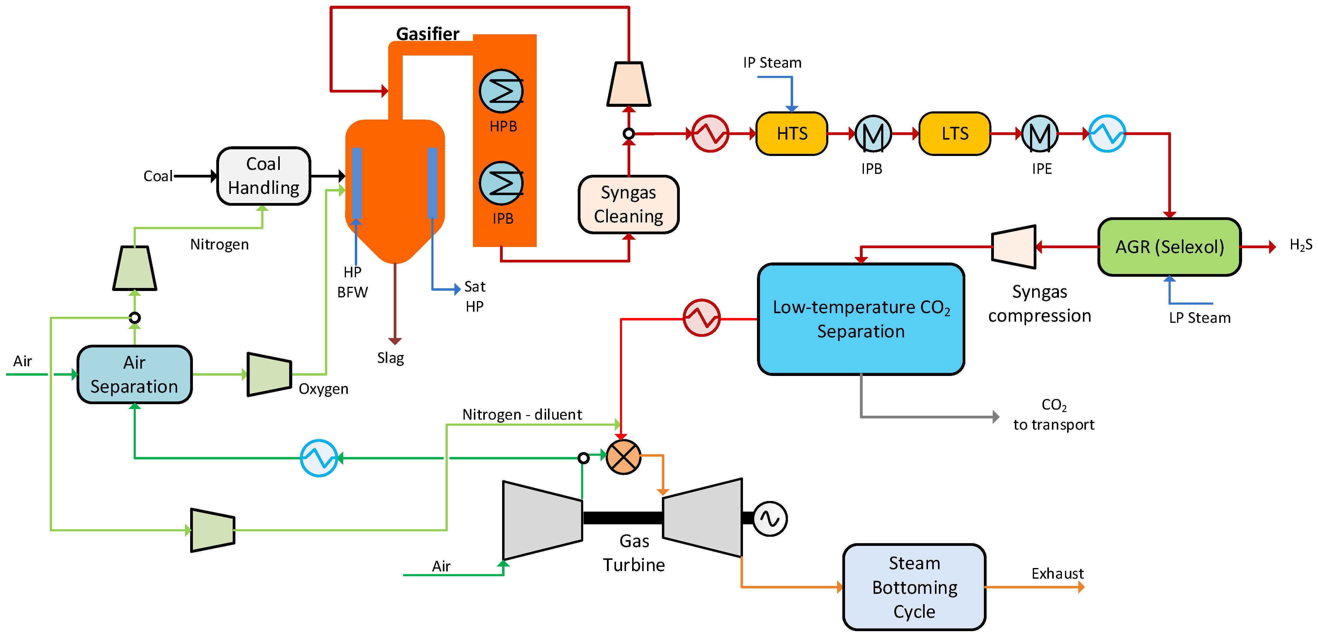
2. Capture Source: Integrated Gasification Combined Cycle

The IGCC configuration used as a framework for this study is based on Anantharaman et al. [23]. The gross electric output from the cycle is around 457 MW. A block diagram including main material streams in the overall process is shown in Figure 1. The dried pulverised coal is pneumatically conveyed by inert nitrogen gas from a cryogenic Air Separation Unit (ASU) into a Shell-type gasifier, which is also fed by compressed oxygen supplied by the ASU. In order to cool the syngas and produce high pressure steam, radiant coolers are used within the gasifier wall. The syngas is then cooled through a gas quench using recycled syngas to reach 900 °C, followed by convective coolers producing high-pressure and medium-pressure saturated steam. After the remaining fly ash is removed through filters, the syngas consists mainly of hydrogen, CO2, H2S, CO and nitrogen. Before H2S removal, Water-Gas-Shift (WGS) is included to convert the CO present in the syngas to CO2, so that the heating value is transferred into creation of hydrogen fuel and CO2 which can be captured. For the case with Selexol as CO2 capture technology, H2S and CO2 are removed in the same cleaning process, but in two different stages where H2S is selectively removed in the first stage. For the case of IGCC with low-temperature CO2 capture, H2S is removed upstream of the capture unit in a dedicated single-stage Selexol process. After CO2 capture, the hydrogen-rich fuel is burned in a gas turbine with air and additional nitrogen from the ASU to limit the temperature in the gas turbine and ensure safe and efficient turbine operation. Finally, the exhaust gas passes through a heat recovery steam generator (HRSG) with a dual pressure steam cycle.

3. Thermodynamic Models, Methodology and Simulation Tools

The extent to which CO2 can be removed from a gas composition by cooling and condensation is governed by the vapour–liquid equilibrium of the mixture in consideration. In order to obtain a high CCR, a large fraction of the CO2 must be condensed. With a sufficient initial CO2 fraction, this can be achieved by a combination of low temperature and high pressure. The chemical composition, in particular the high mole fraction of CO2, and the supply pressure of the synthesis gas, are therefore important in achieving a high efficiency for the capture process.

3.1. Synthesis Gas Data

The synthesis gas after sour water-gas shift and H2S removal is available at 36 bar. Dehydration is, as discussed in Section 4.2.1, mandatory for preventing ice formation in the heat exchangers and thus avoiding a major process malfunction. The normalised synthesis gas key component fractions after drying and sweetening are shown in Table 1. The pressure and flowrate of this material stream are 35.5 bar and 411 t/h, of which the CO2 flowrate accounts for 340 t/h, i.e., 82.7% of the total mass flowrate.

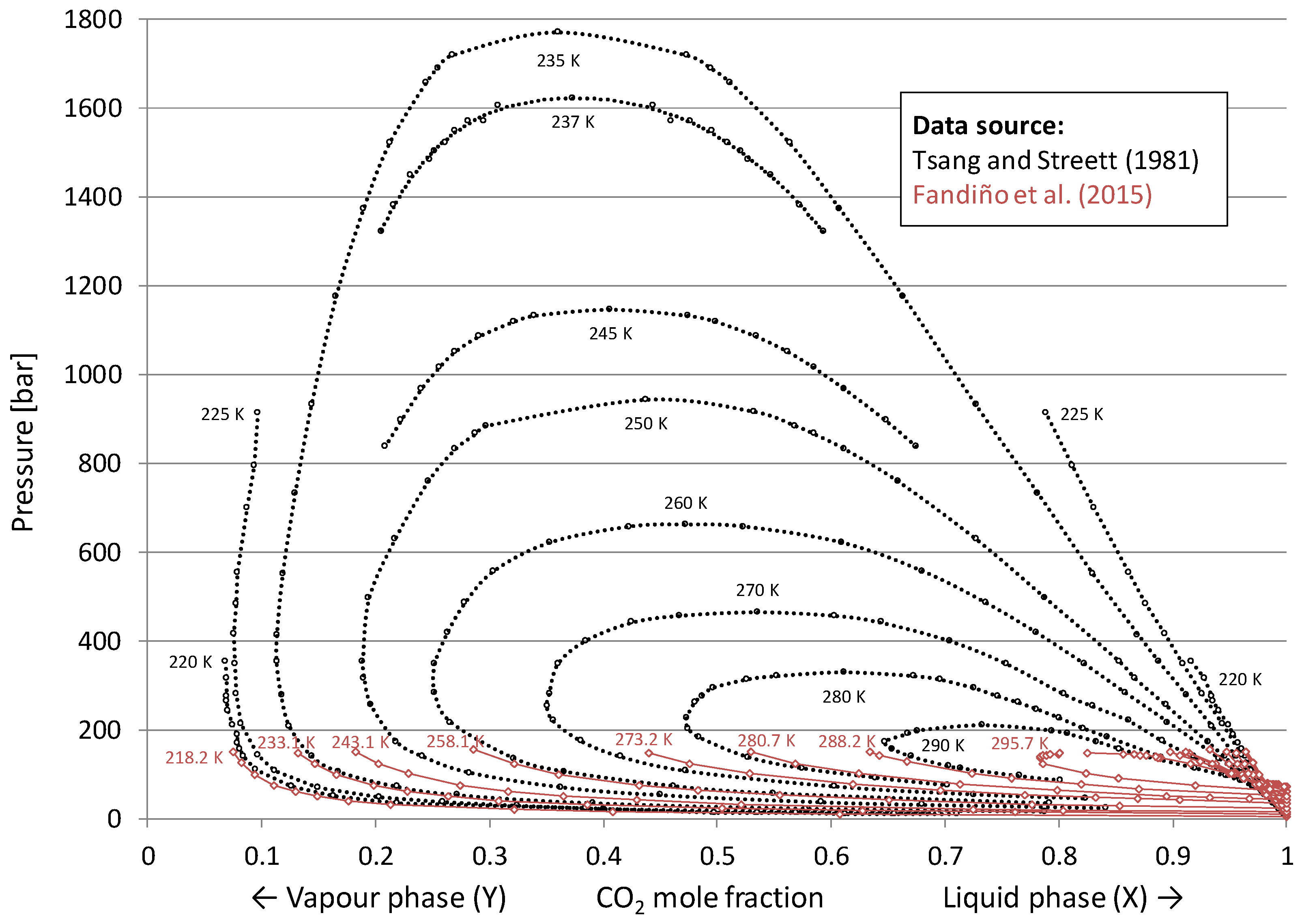
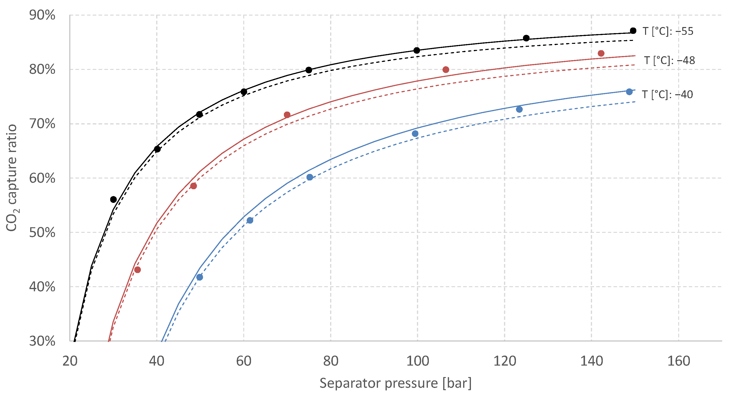
3.2. Vapour–Liquid Equilibrium for the H2/CO2 System

There is a relatively low volume of publicly available literature on vapour–liquid equilibria (VLE) for the H2/CO2 system [24]. For binary systems, experimental data for the relevant temperature and pressure range have been published by Spano et al. [25] and Tsang and Streett [26]. Bezanehtak et al. [27] also measured equilibrium data for the H2/CO2 system in the relevant pressure range up to about 200 bar, but not in the required temperature range relevant to this work. Qian et al. [28] developed a thermodynamic model to predict the phase equilibria for several binary hydrogen systems, including H2/CO2. Fandiño et al. [29] published experimental VLE data for the H2/CO2 and N2/CO2 systems for temperatures between −55 °C and 30 °C and pressure levels up to 150 bar. Vapour–liquid equilibrium data for the binary H2/CO2 system based on results from [26,29] are plotted in Figure 2.
When cooling a pressurised syngas mixture to a partially condensed state and separating the phases, the obtainable liquid yield, and thus CO2 capture ratio, is highly dependent on several factors related to feed composition and vapour-phase and liquid-phase compositions. To derive an approximation for obtainable CO2 capture ratio by phase separation, consider Figure 3 showing the feed and product streams for a single-stage vapour–liquid separator.
Given VLE conditions, a binary H2/CO2 syngas mixture with overall CO2 mole fraction fCO2 is partially condensed if the equilibrium vapour-phase CO2 mole fraction yCO2 at the given temperature and pressure is lower than fCO2. In this case, the syngas can be separated to a vapour and liquid stream with CO2 mole fractions yCO2 and xCO2, respectively. Defining CCR here as the CO2 flowrate of the liquid product relative to that of the feed stream, the steady-state mass balance can be manipulated to giving an expression for CCR as a function of fCO2, xCO2 and yCO2 given in Equation (1).
CCR = x CO 2 ( f CO 2 y CO 2 ) f CO 2 ( x CO 2 y CO 2 )
To what extent pressure, temperature and thus xCO2 and yCO2 influence CCR, depends strongly on the CO2 feed fraction fCO2 as shown in Figure 4. For the higher range of CO2 fraction in the feed and given a fixed separation temperature of −55 °C, the obtainable CCR increases rapidly with separation pressure. This gradient is lower for the lower range of CO2 fractions in the feed, and the separation pressure must be increased considerably to achieve a high liquid yield and thus CCR. For 100 bar separation pressure at −55 °C, the obtainable CCR for the binary mixture under equilibrium conditions is around 59% for 20 mol% initial CO2 fraction, 76% for 30 mol%, and 85% for 40 mol%.
As given in Table 1, the CO2 fraction for shifted and preconditioned syngas in the present work is 38 mol%. Figure 5 shows CCR estimates for this syngas mixture as function of separation pressure and three different temperature levels: −40 °C, −48 °C and −55 °C, which enables a comparison of CCR estimates based on Equation (1) using experimentally obtained measurements (available for selected temperature levels) with estimates based on the process simulator implementation of the chosen equation of state. For each temperature, three different estimates are included:
  • Circular markers are estimates for binary mixtures (38 mol% CO2, 62 mol% H2) based on experimental results from [26,29] (Figure 2).
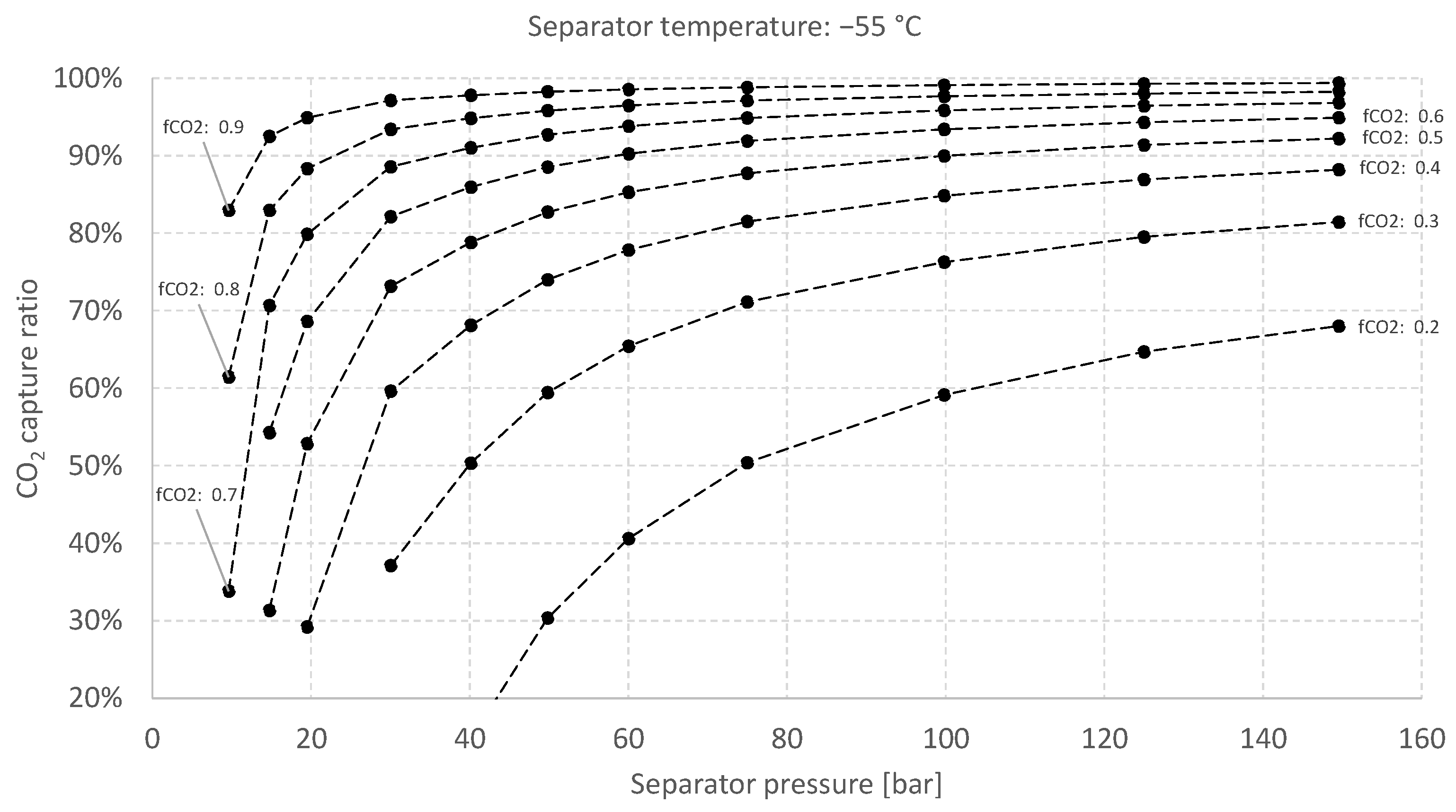
  • Solid lines are estimates for binary mixtures (38 mol% CO2, 62 mol% H2) generated by the process simulation software Aspen HYSYS using the Peng–Robinson equation of state.
  • Dashed lines are estimates for the actual five-component syngas mixture (see Table 1) generated by Aspen HYSYS using Peng–Robinson equation of state. These multi-component estimates indicate that while keeping the CO2 fraction constant, the inclusion of the additional diluents in Table 1 (CO, Ar and predominantly N2) leads to a reduction in estimated CCR.
As a reference to operational experience, Trædal et al. [30] reported the measured CCR, as well as CO2 fractions in the separation products to be very close to equilibrium calculations for phase separation of partially condensed binary N2/CO2 mixtures. The circulated flowrate in their experiments was close to 6 t/d. The separators used were cylindrical and insulated gravitation separators with 100 mm inner diameter and an estimated average liquid retention time in the interval 36–80 s.

3.3. Simulation Software

The low-temperature capture unit was simulated in Aspen HYSYS using the cubical Peng–Robinson equation of state (EOS) with modified binary interaction coefficients. For the high separation pressure and low separation temperature in consideration, the deviation between the results from simulation and experimental data is expected to be low, as indicated by the comparison for the −55 °C isotherm in Figure 5. The plate-fin heat exchanger designs, assessed in detail by using geometric models, were simulated in Aspen MUSE/MULE.

3.4. CO2 Freezing Point Estimation and Implications on Operating Temperature

Due to operation at temperatures close to the CO2 freezing point, prediction of the CO2 freeze-out temperature is important for defining the operating window in terms of temperature and pressure. For most low-temperature capture units for CO2 condensation, the lowest operating temperature is commonly between −53 °C and −56 °C, depending on process type, pressure level and gas mixture [1]. The N2/CO2 system has considerably lower freeze-out temperatures than the H2/CO2 system. As an example, Trædal et al. [30] conducted vapour–liquid separation experiments using a binary N2/CO2 mixture. The separator temperature was maintained at −57.0 °C at 30 bar operating pressure. The experiment was conducted without experiencing operational disturbances, which could potentially arise due to solid CO2 accumulation and clogging. Other factors with impact on the choice of operating temperature are the degree of nonequilibrium conditions in the gas mixture, as well as local temperature conditions close to the heat exchanger surface, where the temperature is closer to the cold-side refrigerant.
In [26], the lowest measured temperature for H2/CO2 vapour–liquid equilibrium data was 220 K, for which the melting point pressure was measured to 357 bar. Fandiño et al. [29] conducted controlled isochoric cooldowns of an H2/CO2 mixture to determine the three-phase line. In the reported experiment, starting at around 138 bar, the first freeze-out of CO2 was observed from a metastable vapour–liquid phase at approximately 217.2 K (approximately −56 °C) and 137 bar.
For the given synthesis gas composition at the assumed separation pressure, the freezing point tool embedded in Aspen HYSYS estimates a CO2 freeze-out temperature of −58.5 °C. The minimum synthesis gas separation temperature used in the process simulations is set to approximately −56 °C. Estimation of CO2 freeze-out temperature is a field in which great care must be taken, and various tools may return diverging temperature estimates. Although −56 °C is assumed to be the bulk-stream minimum temperature in this work, an increase, e.g., to −55 °C or −54 °C, for reducing the risk of freeze-out in cold spots, has only a modest impact on process performance. Another possible measure for increasing the temperature on the heat exchanger surface, and thus for mitigating the risk of CO2 freeze-out, is to increase the cold-side evaporation pressure and thus temperature. This creates a tighter temperature approach in the cold end, which can be compensated for by increasing the heat exchanger surface area and thermal length.
Rather than a showstopper, the minimum separation temperature is first and foremost a design parameter for which considerations of process efficiency, economics, operability and reliability must be balanced against one another.

4. Low-Temperature Capture Processes

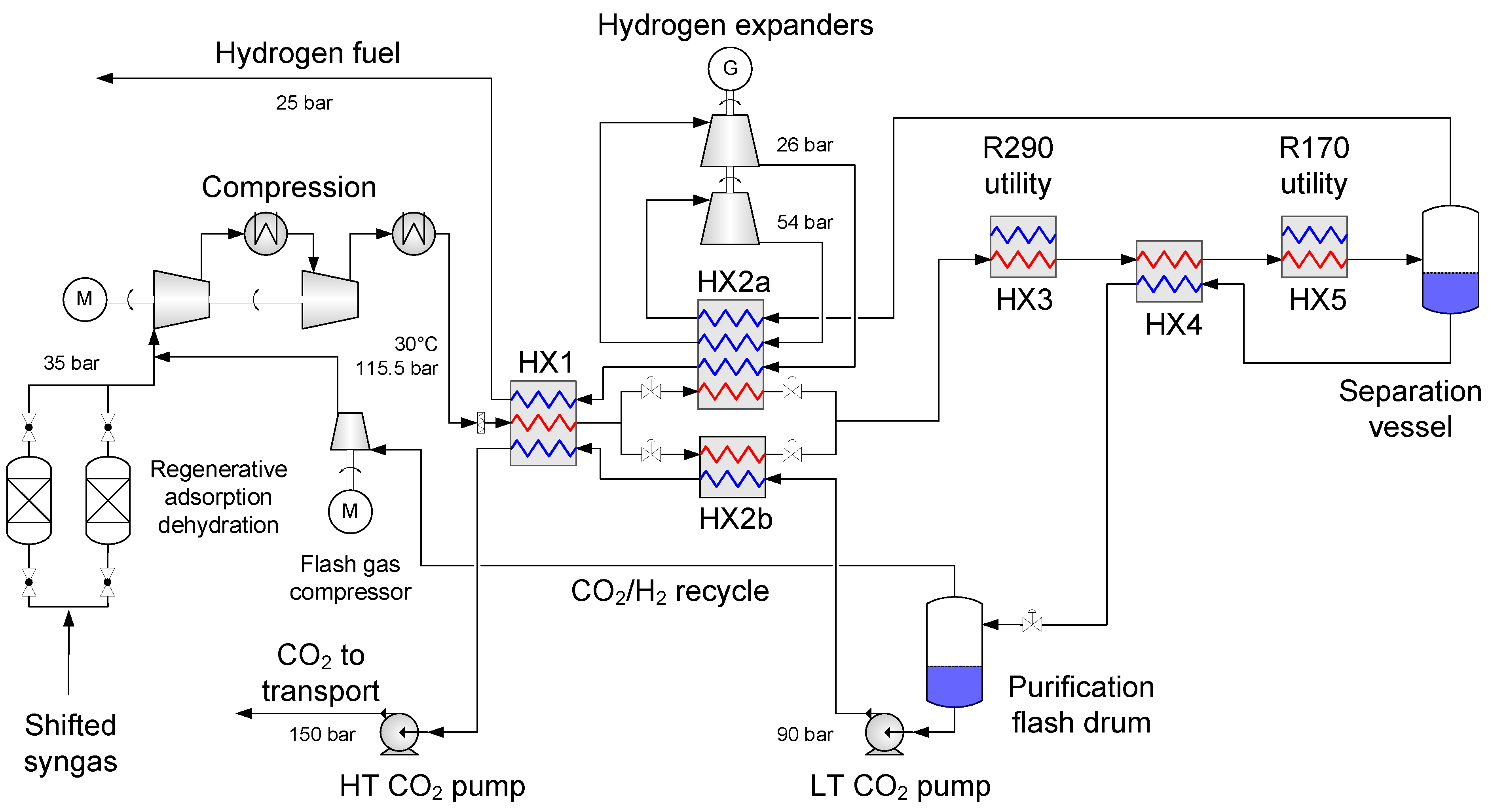
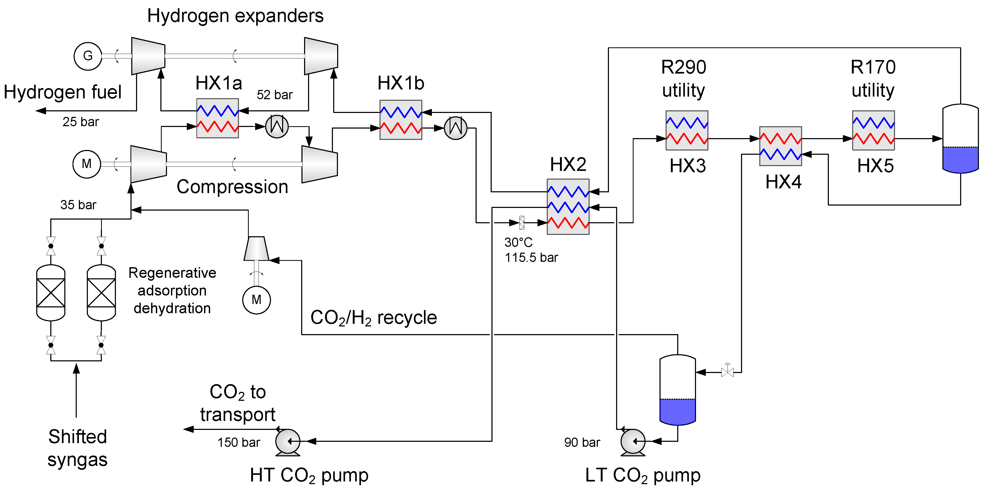
4.1. Baseline Low-Temperature CO2 Separation Process

The hot synthesis gas is required to undergo cooling and water knock-out after water-gas shift and desulphurisation. The shifted synthesis gas feed in the process flow diagram in Figure 6 is assumed to be saturated with water at typically 30–40 °C temperature. After deep dehydration in regenerative molecular sieve beds, the requisite synthesis gas pressurisation is dependent on the targeted CCR, as shown in Figure 5. In this work the targeted CO2 capture ratio is 85%, which corresponds to a CO2 capture rate of 6.94 kt/d on a mass basis. Assuming an availability of 7500 h per year [23], this corresponds to an annual rate of 2.17 Mt/y. With CCR targeted at 85%, the discharge pressure of the synthesis gas compressor train was specified at 116 bar. Although this may seem like an exceedingly high pressure, e.g., in comparison with oxy-combustion capture units [31], the actual pressure ratio and volume reduction from suction to discharge is considerably lower than for flue gas compressors in oxy-combustion CO2 purification units or CO2 compressors in post-combustion capture. Whereas oxy-combustion and postcombustion compression units have pressure ratios of roughly 30 and 60–80 respectively, the corresponding number is about 3.3 for the synthesis gas compressor train. As shown in the process flow diagram (see Figure 6), a two-stage compressor train is used for raising the synthesis gas pressure from 35 bar to 115.5 bar. More details on the compressors are given in Section 4.2.3.
After compression and aftercooling, the high-pressure synthesis gas enters the low-temperature heat exchanger network. In HX1, the stream is cooled by counter-flow heat exchange against the hydrogen-rich and CO2-rich separation products. The synthesis gas outlet temperature from HX1 is roughly −8 °C. At this point the stream is split into two branches with a split ratio close to 70:30 entering the parallel heat exchangers HX2a and HX2b. The largest branch is cooled and partially condensed in the four-stream heat exchanger HX2a, while the smallest branch is cooled against pressurised liquid CO2 in HX2b. After passing through the parallel heat exchangers, the two stream branches, now partially condensed, are mixed and the resulting temperature is about −36 °C. The synthesis gas stream is further cooled and condensed in three heat exchangers in serial arrangement: to −39 °C in HX3, which is a propane (R290) evaporator where the cooling duty is provided by an auxiliary refrigeration cycle, further to −43 °C in HX4 by cooling against the cold, liquid CO2 stream from the first separator, and to about −56 °C in HX5 in an ethane (R170) evaporator, which is also part of the auxiliary refrigeration cycle. The basic layout of the R290/R170 refrigeration cycle is provided in Section 4.2.5.
Upon cooling to the final separation temperature, the partially condensed synthesis gas is separated into a hydrogen-rich gaseous phase and CO2-rich liquid phase. The cold and high-pressure gas product now enters the return path in the process towards its target state of 25 bar, which is the specified gas turbine combustor fuel pressure. In order to maximise the recuperation of thermal and mechanical energy contained in this stream, the hydrogen fuel is utilised for cooling the synthesis gas in HX2a. The stream is expanded two times and passes through the cold side of heat exchanger HX2a at three different pressure levels (113.5 bar, 54 bar and 26 bar). The design and simulation results for HX2a is further elaborated in Section 4.2.2. The turboexpanders serve two purposes:
  • Enabling a temperature drop to about −53 °C so that the hydrogen-rich fuel stream can be utilized as much as possible to provide cold duty to heat exchanger HX2a.
  • Generating recoverable power to be utilised in the process or increase the net power output.
This dual utilisation of the pressure-based exergy contained in the high-pressure hydrogen fuel stream contributes substantially to reducing the net power input and is crucial for obtaining an efficient low-temperature separation process.
After passing three times through HX2a, the hydrogen-rich fuel stream enters the cold side of HX1, in which the stream contributes to precooling the synthesis gas together with the captured CO2 stream. Upon leaving this heat exchanger, the fuel stream is passed on to the IGCC gas turbine combustor at 25 bar pressure.
The CO2-rich liquid product from the synthesis gas separation vessel is heated in HX4 before entering a flash drum for CO2 purification and hydrogen recovery. Before entering this purification unit, the liquid CO2 stream is throttled to roughly 7–8 bar pressure and the generated flash gas, made up mainly of CO2 but also a considerable fraction of hydrogen, is recycled in order to minimise the hydrogen slip. A flash gas compressor is required for raising the pressure of the recycle stream to match that of the synthesis gas feed, causing a minor energy penalty relative to the recovered hydrogen energy. The purified liquid CO2 is pumped to 95 bar and subsequently enters the cold side of HX2b. Upon leaving HX1, the dense-phase CO2 stream is pumped to further raising the pressure to 150 bar, which is the defined transport pressure.
The flash purification unit constitutes an important difference from other proposed process schemes, for instance [12,13]. Flashing the liquid CO2 at lower pressure, for instance 7–8 bar, increases the hydrogen recovery as well as improves the CO2 quality for transport and storage. Furthermore, the flash separator can also be utilised for producing liquid CO2 for shipping or other forms of bulk transport, either in a permanent process layout or temporarily in an early-phase commissioning with the real option of retrofitting to produce high-pressure CO2 after a potential pipeline infrastructure rollout.

4.2. Process Component Design and Performance

In order to further verify the viability of the proposed low-temperature CO2 capture unit, the performance of different components and subsystems must be verified. This applies in particular to heat exchangers, compressors and expanders, the key components in the capture unit on which the overall process performance and efficiency depend.

4.2.1. Synthesis Gas Dehydration

After water-gas shift and desulphurisation in a dedicated unit, the synthesis gas is required to undergo dehydration before entering the low-temperature heat exchanger network. As is the case also for cryogenic processes, such as liquefied natural gas (LNG) plants and air separation units (ASU), ice formation in heat exchangers or any other part of the process must be avoided. Although the low-temperature synthesis gas separation unit will operate at far higher temperature than LNG units and ASUs, near-complete dehydration is still required. The water saturation vapour pressure over ice is 1.08 Pa at −60 °C [32] and the dew point should be significantly below the lowest synthesis gas temperature exposure in the process. Hence, in order to ensure safe operation, deep dehydration to water content between 0.1 and 1 ppm should be targeted, depending on the desired dew point safety margin. Hence, the use of molecular sieves will likely be required.
In addition to eliminating the risk of water ice formation, dehydration generally reduces the risk of other operational problems such as corrosion. According to the Standards of the Brazed Aluminium Plate-Fin Heat Exchanger Manufacturers’ Association [33], trace impurities and acid forming gases create no corrosion problems in aluminium plate-fin heat exchangers when the gas is already dehydrated. The use of plate-fin heat exchangers is further elaborated in the following.

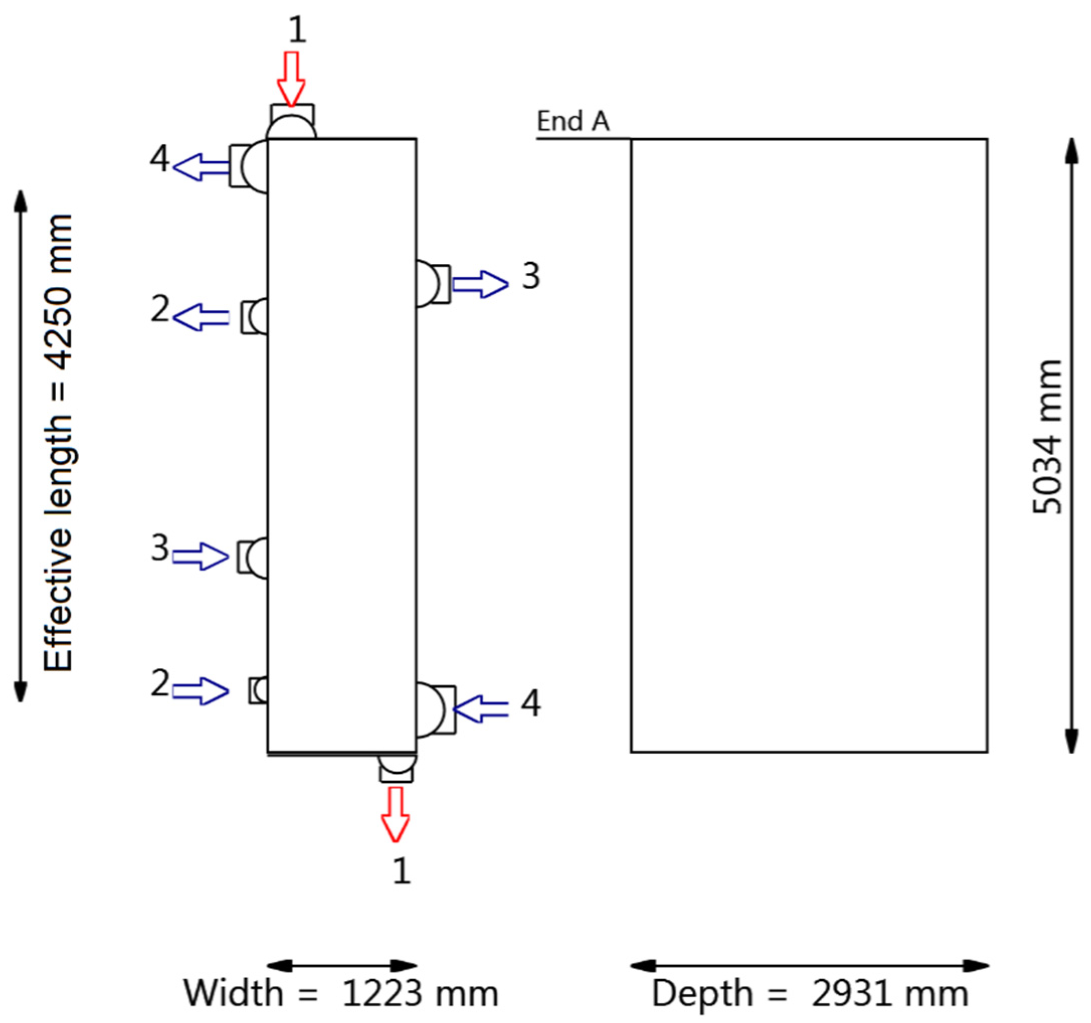
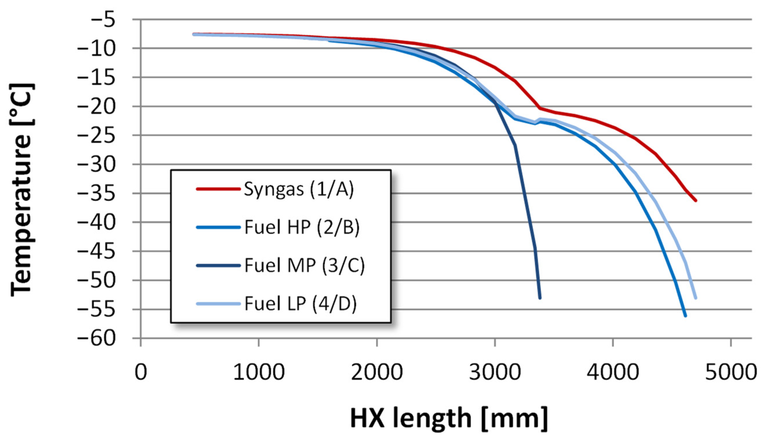
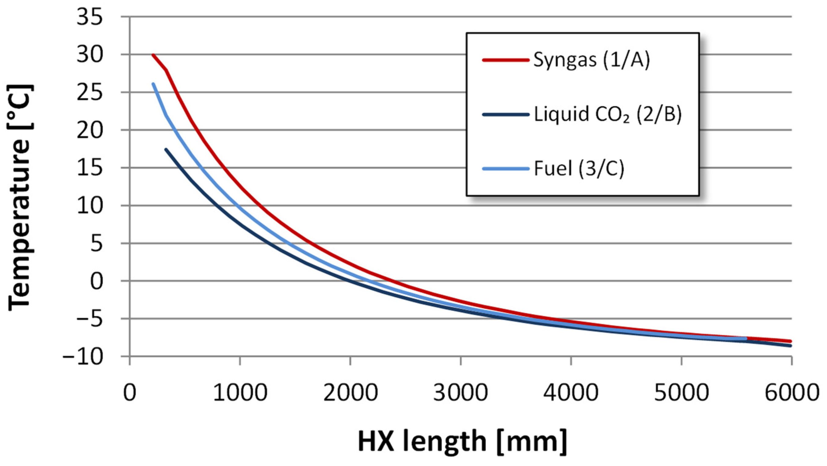
4.2.2. Heat Exchanger Design

In the process configuration shown in Figure 6, the four-stream heat exchanger HX2a is the most complex in the low-temperature capture unit. The major stream branch containing about 70% of the total feed flowrate is, as mentioned, cooled from −8 °C and partially condensed by heat exchange against three cold streams. In the heat exchanger design, emphasis has been on obtaining a feasible geometry for HX2a. If a feasible HX2a design can be made, the design of the remaining heat exchangers is trivial in comparison. Hence, the design of HX2a has been the most thoroughly investigated task in the present work.
Selection of the type of heat exchanger to be used for HX2a is the first decision to be made. Due to the need for tight heat integration with small temperature differences that require a counterflow type of heat exchange, as well as the number of streams involved, a brazed aluminium plate-fin heat exchanger (PFHX) is a functional choice for this application. PFHXs can be designed for pressures above 100 bar and temperatures as low as 4 K [33] and represent a mature technology in low-temperature and cryogenic engineering fields such as air separation, natural gas liquefaction, hydrogen liquefaction and helium liquefaction. Another feature of PFHXs is the possibility of including up to ten streams inside a single heat exchanger core. Due to the extended fin surface, very high heat transfer rates, close temperature approaches, and high thermal efficiencies can be obtained. For the same reason, these units are very compact with large heat transfer surfaces per unit volume (~1000 m2/m3) and low weight. It is, however, important to avoid maldistribution of the process streams. Care must be taken when designing the distribution section and deciding the stream and layer pattern inside the heat exchanger core to avoid uneven load and possibilities of creating unacceptable thermal stress levels.
For the separation pressure assumed in the process model (113.5 bar baseline value) and the specified hydrogen target pressure (25 bar), the HX2a design must ensure that pressure losses in channels are curbed to acceptable levels. Here, acceptable levels translate to heat exchanger pressure losses allowing sufficient pressure reduction for the fuel expanders to generate temperature depressions to −53 °C at the outlet. Hence, a maximum value of 1 bar for each stream was used as design criterion. Another design parameter is the outlet temperature for the cold streams. From the process point of view, the high- and intermediate-pressure fuel stream outlet temperatures should preferably be uniform and slightly lower than −8 °C.
HX2a, as well as HX1 and HX2b, were simulated with the commercial software Aspen MULE. Required input parameters include a defined layer stacking, detailed geometry and process input data. Each layer is calculated individually using individual metal temperatures for each wall for each position in the axial direction and calculates the stream-to-wall heat transfer. Built-in proprietary models for heat transfer (j-factor) and pressure drop (f-factor) based on experimental research, were used. It should be noted that manufacturers have their own proprietary fin designs and override these correlations by providing specific tables for j- and f-factor when doing a PFHX design, but the correlations from Heat Transfer and Fluid flow Service (HTFS) do not necessarily provide less accurate results than manufacturers’ own data.
The resulting size of HX2a is shown in Figure 7. The plate-fin heat exchanger is vertically oriented with total and effective lengths of ca. 5 m and 4.25 m, respectively. Each layer for the single hot stream (1/A) is adjacent to layers with cold hydrogen-rich gaseous streams (2/B, 3/C, 4/D) in the recurring pattern (ACABAD). The total number of stacked layers is 348 (174 A-layers plus 58 B-, 58 C- and 58 D-layers), resulting in a total stacking depth of about 2.9 m.
The aggregate temperature profiles for each process stream in HX2a are plotted in Figure 8. In the proposed heat exchanger design, the synthesis gas stream (1/A) and the low-pressure, hydrogen-rich fuel stream (4/D) exchange heat over the full effective length. The two other fuel streams are withdrawn 1.4 m and 1.6 m from the top/warm end, giving these streams 0.6–1.0 °C lower outlet temperature than the low-pressure stream. This is advantageous for the expansion processes, as a temperature drop to about −53 °C can be obtained with somewhat lower pressure ratio.
Temperature profiles for heat exchangers HX1 (3 streams) and HX2b (2 streams) are plotted in Figure 9 and Figure 10, respectively. A brief summary of heat exchanger temperature and duty data is given in Table 2.

4.2.3. Synthesis Gas Compressors

Synthesis gas compression is the main driver of power demand for the low-temperature CO2 capture unit. Hence, high compressor efficiency is important for obtaining high overall efficiency for the capture unit, and the compressors should be designed with this objective in mind.
The synthesis gas suction volumetric flow rate is approximately 15,000 m3/h for the first compression stage. This is well within the design window for industrial centrifugal compressors, which typically range between 102–103 m3/h and 105–106 m3/h in magnitude for volumetric flowrate. The maximum pressure ratio per compressor stage is limited by the maximum impeller tip speed, which, in turn, is limited by either the speed of sound and Mach number, or material constraints with respect to centrifugal forces and rotor stability. For the synthesis gas composition in consideration, with a molar mass of 20.9 g/mol, the maximum stage pressure ratio is likely to be close to 2. Hence, two compressor stages are needed to obtain a total pressure ratio of about 3.3. To maximise the energy efficiency of the two-stage compressor train, intercooling is included, and the pressure drop in inter- and aftercoolers is assumed to be 0.5 bar per heat exchanger. With a first-stage pressure ratio of 1.85, close to the geometric mean pressure ratio, followed by intercooling, the resulting second-stage suction volumetric flowrate is approximately 7800 m3/h. With a second-stage suction pressure of 65.5 bar, the pressure ratio is set to 1.77 in order to obtain a 116 bar discharge.
Efficiencies specified for the two compressor stages are considered to be rather conservative. The design-point isentropic efficiency is assumed to be 85% for the larger first-stage compressor and correspondingly 82% for the second stage. The resulting power consumption based on these efficiencies is 11.6 MW and 10.8 MW for the first and second stage, respectively.
The third gas compression unit located in the process flow diagram in Figure 6 is the compressor recycling the flash gas containing recovered hydrogen diluted with CO2 back to be mixed with the dehydrated feed stream. With a duty and suction volumetric flowrate of 1.1 MW and 2300 m3/h, this compressor is considerably smaller than the synthesis gas feed compressors, but still within the range for centrifugal turbo-compressors. Although the recycle stream contains recovered hydrogen (approximately 19 mol%) the main constituent is still CO2 (67 mol%) and the estimated molar mass of the gas mixture is 34.2 g/mol. The maximum pressure ratio for this gas composition is likely to be in the range of 2.5–3 per impeller and with a total pressure ratio of 4.55; two impellers should be applicable for this compression. The inlet temperature is equal to that of the CO2 purification flash drum, −56 °C, and no intercooling is therefore required. The overall isentropic efficiency of the recycle compressor is assumed to be 80% and the resulting discharge temperature is about 67 °C.
A summary of the process compressors, including CO2 pumps and refrigeration cycle compressors is given in Table 3.

4.2.4. Fuel Expanders

As explained in Section 4.1, the fuel expanders have two functions contributing to increased efficiency: power recovery from compressed-gas expansion and increased process-internal refrigeration capacity. Summing up the expander duties in Table 3, the gross expander power output calculates to 9.6 MW, which is considerable compared to the total compressor duty of roughly 30 MW. Based on this figure it is obvious that power recovery from the high-pressure hydrogen-rich fuel product is crucial for the overall capture-unit efficiency. The highest inlet pressure level, about 110 bar, is within the state-of-the-art range for industrial turboexpanders. In the process simulations, isentropic efficiencies of 88% and 85% for the two expander units are assumed. These should be considered as realistic efficiency figures when considering the fact that far smaller, high-efficiency machines are state-of-the-art in cryogenic processes such as hydrogen and helium liquefaction. Cryogenic hydrogen and helium turboexpanders with considerably lower volumetric flowrates and impeller diameter are available with efficiencies above 85% [34]. The specific enthalpy drop in the two expander units are 144 kJ/kg and 140 kJ/kg, respectively. This is in the higher end of what is feasible for single-stage expanders and each unit may therefore consist of two or more impellers in series.
Electric power recovery, by adding a generator to the shaft, is assumed in the current process model. A rather conservative overall mechanical-to-electric power recovery efficiency of 90% is assumed. An obvious alternative to electric conversion of the shaft power generated is the use of compressor-loaded turboexpanders where each stage could drive one synthesis gas compressor stage. If direct pairing between the expander stages and feed compressor stages through gears and shafts is feasible, this could give higher net power recovery efficiency, but on the other hand a less flexible and controllable configuration.

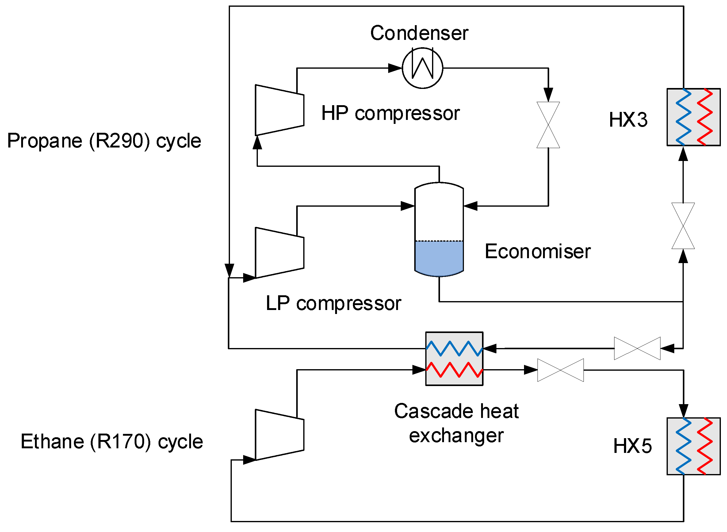
4.2.5. Auxiliary Refrigeration

The auxiliary refrigeration system supplying the required external cooling duties in the capture unit is assumed to be a conventional vapour-compression cascade cycle with R290 and R170 as refrigerants. As shown in the simplified process scheme in Figure 11, the R290 vapour-compression cycle has two stages due to its large temperature operating range. The evaporation pressure has been set slightly above atmospheric pressure, in this case 1.015 bar, corresponding to an evaporator cold-side temperature of about −42 °C. Two R290 evaporators are included in the process scheme: process heat exchanger HX3 where high-pressure synthesis gas is cooled to about −39 °C, and the cascade heat exchanger where R170 is condensed by heat exchange against evaporating R290. The R290 high-pressure level is dependent on ambient conditions and the cooling medium (air, water). In this work the hot-side outlet temperature in the ambient condensers is specified to 30 °C, and the sub-cooling level is set to 3 °C for all condensers. The resulting R290 high-pressure level based on these specifications is estimated to 12.1 bar. The intermediate pressure level is set to 3.5 bar, i.e., the approximate geometric mean value of the minimum and maximum pressures.
The single-stage R170 refrigeration cycle pumps heat from the process heat exchanger HX5 to the cascade heat exchanger. The condenser pressure is given by the R290 evaporation temperature in combination with the specified minimum temperature difference between the evaporating and condensing fluids. This temperature difference was specified at 5 °C in the current model and gives an R170 high-pressure level of 8.5 bar. The low-pressure level is determined by the evaporator temperature, which in turn is a function of the synthesis gas hot-side outlet temperature and the specified cold-end minimum temperature approach in HX5. These two parameters were specified at about −56 °C and 1 °C, respectively, giving a low-pressure level of approximately 4.2 bar.
Compressor data for the R290 and R170 compressors are given in Table 3. As can be observed, the volumetric flow rates are in the same order of magnitude as the synthesis gas compressors. The isentropic efficiencies are therefore assumed to be similar, but since the duties are considerably lower, they do not involve the same sensitivity with respect to overall power requirement and energy efficiency.
Although other process configurations are available, the layout in Figure 11 was designed with an economiser. Other combinations of refrigerants are also possible, and obvious alternatives are, for example, ammonia (R717), propylene (R1270), CO2 (R744), or alternatively mixed refrigerants [18]. The main purpose of the current refrigeration cycle design is to obtain representative figures for the coefficient of performance (COP) and thus power estimates for supplying the requisite cooling duties in the capture unit.

4.3. Alternative Process Layout: High-Temperature Expanders for Improved Operability

High degree of process heat and power integration is a prerequisite for efficient CO2 capture by low-temperature synthesis gas separation. The cooling potential of the cold separation products must be utilised through heat recuperation against hot feed streams, and the difference between the respective separation pressure and the pressure of the fuel product must be exploited by generating power using expanders. Although a high degree of process integration will contribute to increased efficiency, there are always techno-economic trade-offs to consider in this regard. As an example, process integration measures may, to a certain extent, compromise plant operability as the interdependence and feedback between subprocesses increase.
An alternative process configuration for improved operability is shown in Figure 12. Unlike the baseline configuration, the hydrogen expander outlet streams are not used for cooling the feed stream in this scheme, but instead arranged to utilise intercooler waste heat for increased power generation. Compared to the base case, this enables a far less complex multistream heat exchanger; HX2 versus HX1, HX2a and HX2b combined in the base case. On the other hand, two waste heat recuperators, HX1a and HX1b, were added to the process. The inlet temperatures to the second compression stage and HX2 are controlled by the intercooler and aftercooler downstream of HX1a and HX1b, respectively, and the process is hence less sensitive to fluctuations in the flowrate and outlet temperature of the hydrogen expanders.
The expander inlet temperatures are increased by heat exchange against hot compressor discharge streams. As a basis for the energy calculations summarised in Section 5.3, a 30 °C minimum temperature approach is assumed. In the current model the expander inlet temperature is therefore around 60 °C for both expanders and the outlet temperatures are around 6 °C.
Energy results were also calculated for a further simplification of the process in which recuperators HX1a and HX2a are omitted and replaced by ambient heat exchange. In this case, denoted “Improved operability (II)” in Section 5.3, the fuel stream is heated, directly or indirectly, by ambient heat sources prior to expansion, and an expander inlet temperature of 10 °C is assumed.

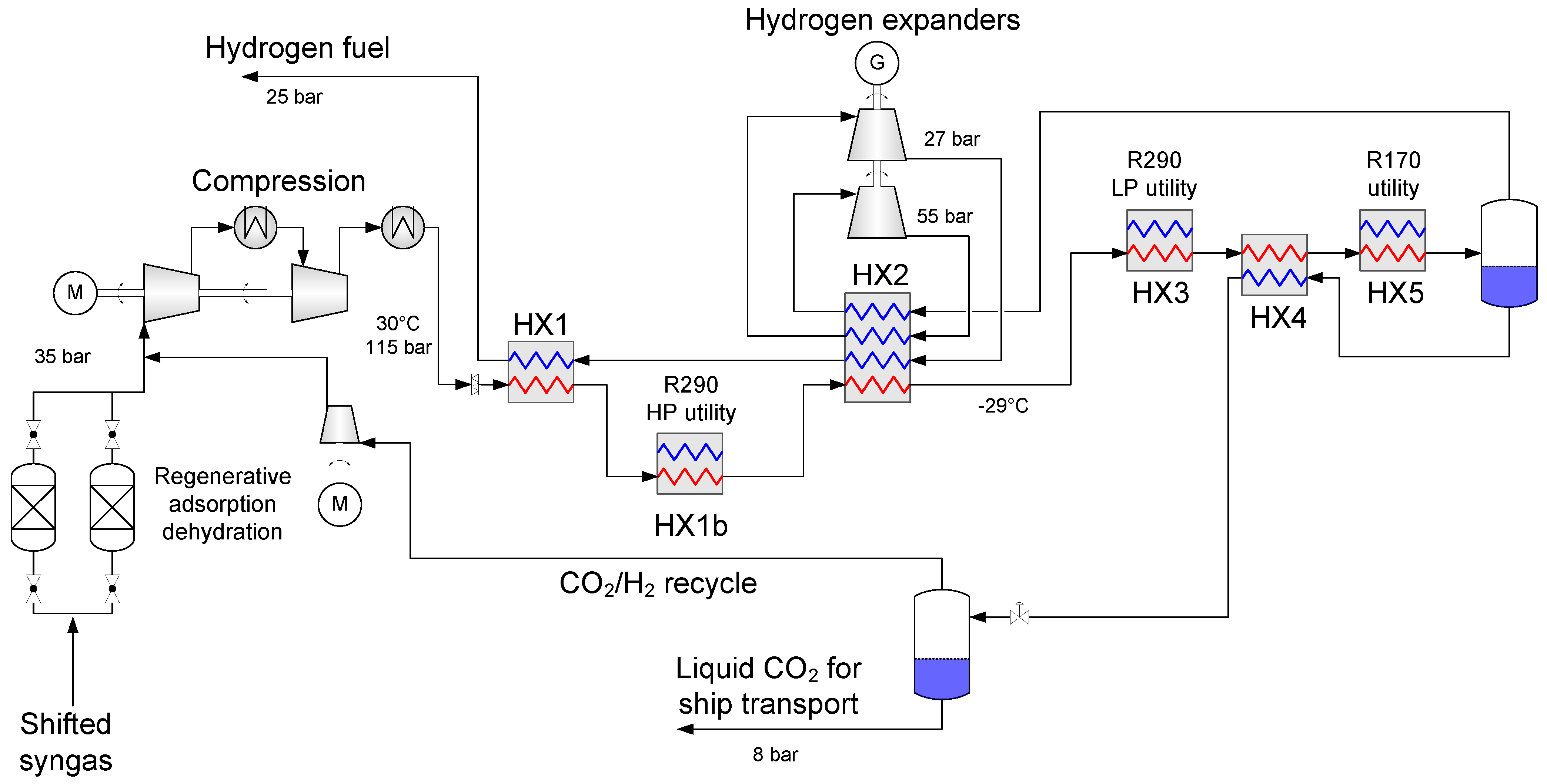
4.4. Alternative Process Layout: CO2 Liquefaction for Ship Transport

In the baseline low-temperature capture concept for pipeline transport, CO2 is condensed and liquefied at conditions relatively close to common specifications for semi-pressurised ship transport of CO2, typically −55 °C and 6.5 bar [35]. Furthermore, the liquefied CO2 is pumped to high pressure and heated after the purification unit to cool down the synthesis gas feed and thus maximise the thermal energy recovery potential.
To retain the separated CO2 in a liquid phase ready for ship transport, the process design can be modified to deliver the purified liquid CO2 as a product stream, as shown in the process flow diagram in Figure 13. As the liquid CO2 product is extracted directly from the purification separator, the external cooling requirement for the process increases due to less internal heat recuperation in the process. In the process scheme for liquid CO2, the share of refrigeration duty provided by auxiliary refrigeration is, therefore, larger than in the baseline case. In the process layout in Figure 13, an additional cooling level around −10 °C (cold-side temperature of HX1b) has been included to increase the overall energy efficiency. Another difference from the baseline case to be noted is the absence of HX2b. The full synthesis gas feed stream thus passes through HX2, which corresponds to HX2a in the baseline case.

5. Results, Discussion and Sensitivity Analysis

This section presents and discusses the energy results obtained for the baseline process scheme. Further, the results are complemented with a sensitivity analysis in which the impact of process parameters on the power requirement is evaluated and discussed. Finally, a results comparison is made for the four different process schemes.

5.1. Baseline Energy Results

Power figures for the main components and subsystems in the baseline process scheme, including estimated net and specific power requirements, are summarised in Table 4. The net specific power requirement is estimated to 273 kJe/kgCO2. For a similar synthesis gas composition but with a somewhat lower feed pressure, the corresponding specific power was estimated to 0.29 MJe/kgCO2 for a marginally lower CCR [10]. The slight difference is mainly attributable to the increased pressure ratio in the synthesis gas compression section, which is the main driver of power demand in the capture process. The corresponding figure for specific power requirements obtained in [12] was 328 kJe/kgCO2, and from [16] estimated to 333 kJ/kgCO2 based on our conversion from absolute to specific figures. However, these figures are for different reasons not directly comparable to the specific power requirements obtained in this study. The respective values for CCR are different; 85% in this work versus approximately 90% in [12] and 92.6% in [16]. In addition to CCR, differences in synthesis gas composition and feed pressure, as well as the discharge pressure of the decarbonised fuel gas, also complicate a level comparison. It still seems that the differences between the results are generally consistent and to be expected. It is clear, for instance, from the CCR predictions made in Figure 5, that the marginal CCR decreases with increasing separation pressure, and the CCR may theoretically even decrease at extreme pressure levels, if applied. This can be understood from Figure 2, where the equilibrium CO2 mole fraction in the vapour phase yCO2 has a minimum value for each isotherm and increases again with increasing pressure level beyond the pressure, resulting in the minimum value for yCO2. Net power requirements will increase steeper in proportion to CCR, and the specific power requirements will, therefore, be strictly increasing. For synthesis gas feed compositions with CO2 fractions around 40%, CCR up to 85% seems relatively easy to obtain, while the marginal power requirements increase rapidly beyond this point. Hence, it can be expected that the net specific power requirement is significantly higher for 90% than 85% CCR, and the latter figure has been indicated as a practical and near-optimal capture rate also in previous works [10,14,17].

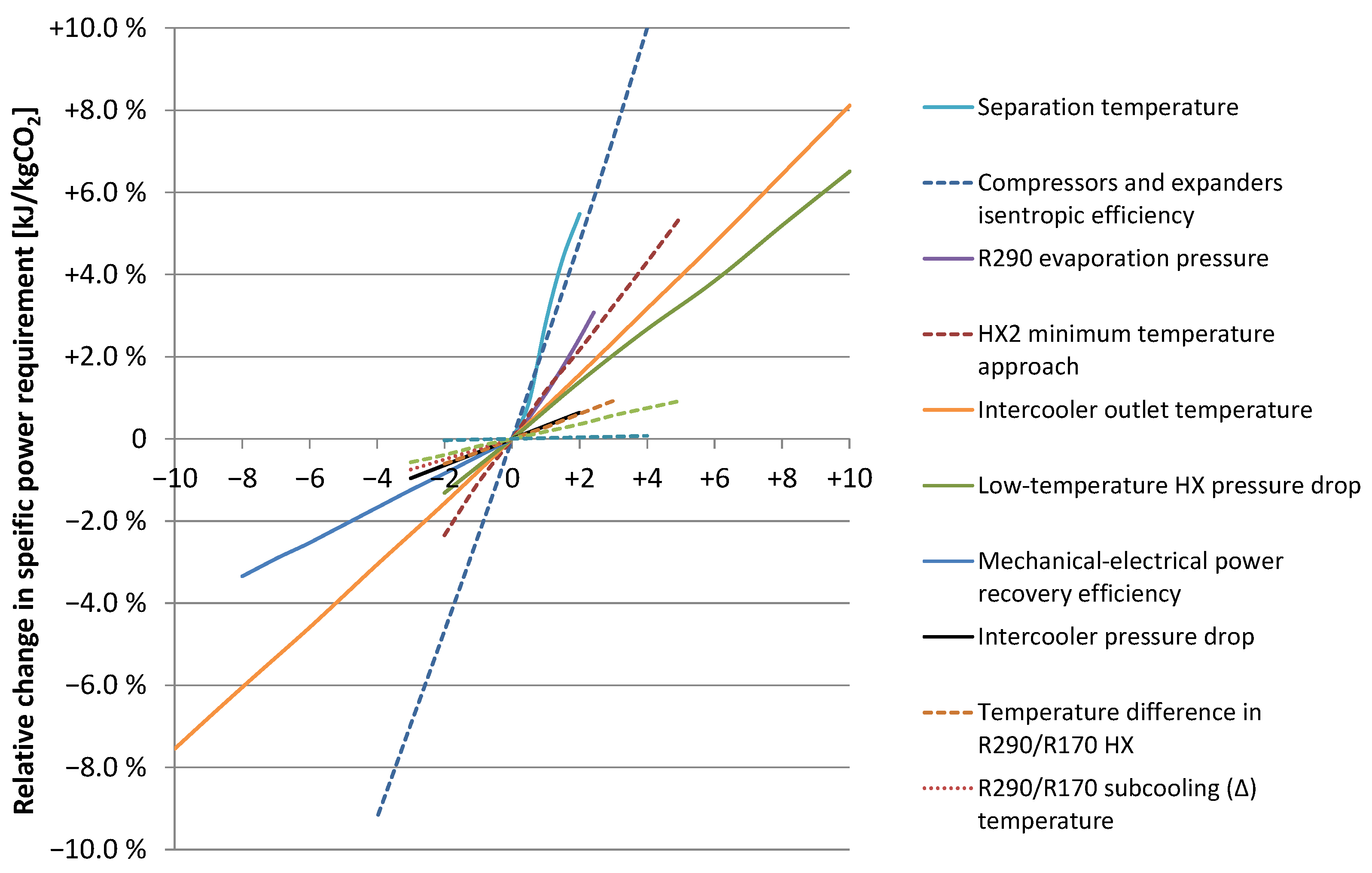
5.2. Sensitivity Analysis for the Baseline Case

The capture-unit simulation model comprises numerous process units such as heat exchangers, compressors and expanders. As stated, assumptions for process unit performance are considered to be on the conservative side with respect to state-of-the-art for the various technologies involved, and all assumptions have a certain impact on the overall capture-unit performance. It is still of high interest to investigate the sensitivity of the power requirements to the various input parameters. As an example, for the design of PFHX HX2a in the base case, the values for pressure drop estimated in the detailed geometric modelling turned out to be significantly lower than those assumed initially. Hence, sensitivity analyses in both directions are of equal interest, i.e., unit performances superior as well as inferior to those initially specified.
Twelve different parameters were included in the analysis, and the results are plotted in Figure 14. Due to the differences in unit and scale for the various parameters investigated, it is obvious that the slope for each curve plotted in the diagram does not give a representative impression of the sensitivity of the corresponding parameter relative to the other parameters. Due to the significant differences in slope, however, the investigated parameters can still be divided into rough categories of high, medium and low sensitivity. Two parameters, as indicated in Table 5, are reversed along the horizontal x-axis in order to give the slopes for all curves positive signs and thereby enable a more convenient graphical comparison.
Among the less influential parameters are those concerning superheating, sub-cooling and cascade temperature differences in the auxiliary R290–R170 refrigeration cycle. Another group of less sensitive parameters are hot-side pressure drops and cooling water pumping power for the intercoolers.
The slope of the curve for power recovery efficiency from fuel expanders is rather moderate. However, as the possible improvement from the 90% baseline value could be considerable, so is the potential reduction in power requirement. For 98% mechanical-to-electrical power recovery efficiency the net power requirement is reduced by 3.3% relative to baseline.
Pressure drops in low-temperature heat exchangers are found to be rather sensitive parameters. The same applies to the intercooler outlet temperature, which is governed mainly by ambient temperature conditions. Two other parameters also considered to be rather sensitive are the minimum temperature approach in heat exchangers (in this study exemplified by HX2-a and HX2-b) and the lowest allowed pressure level in the R290 refrigeration cycle. The baseline value for minimum approach, 3 °C temperature difference, was specified rather conservatively. To illustrate this, the minimum temperature approach in the geometric models for HX1, HX2a and HX2b turned out to be considerably lower than what was assumed in the baseline model.
The perhaps most sensitive parameters pointed out in the analysis are the efficiency vectors for compressors and expanders, as well as the minimum allowed synthesis gas separation temperature. These findings emphasise the importance of verifying turbomachinery efficiencies and conducting thermodynamic simulations and operational experiments for identifying the CO2 freeze-out temperature for the relevant synthesis gas compositions.

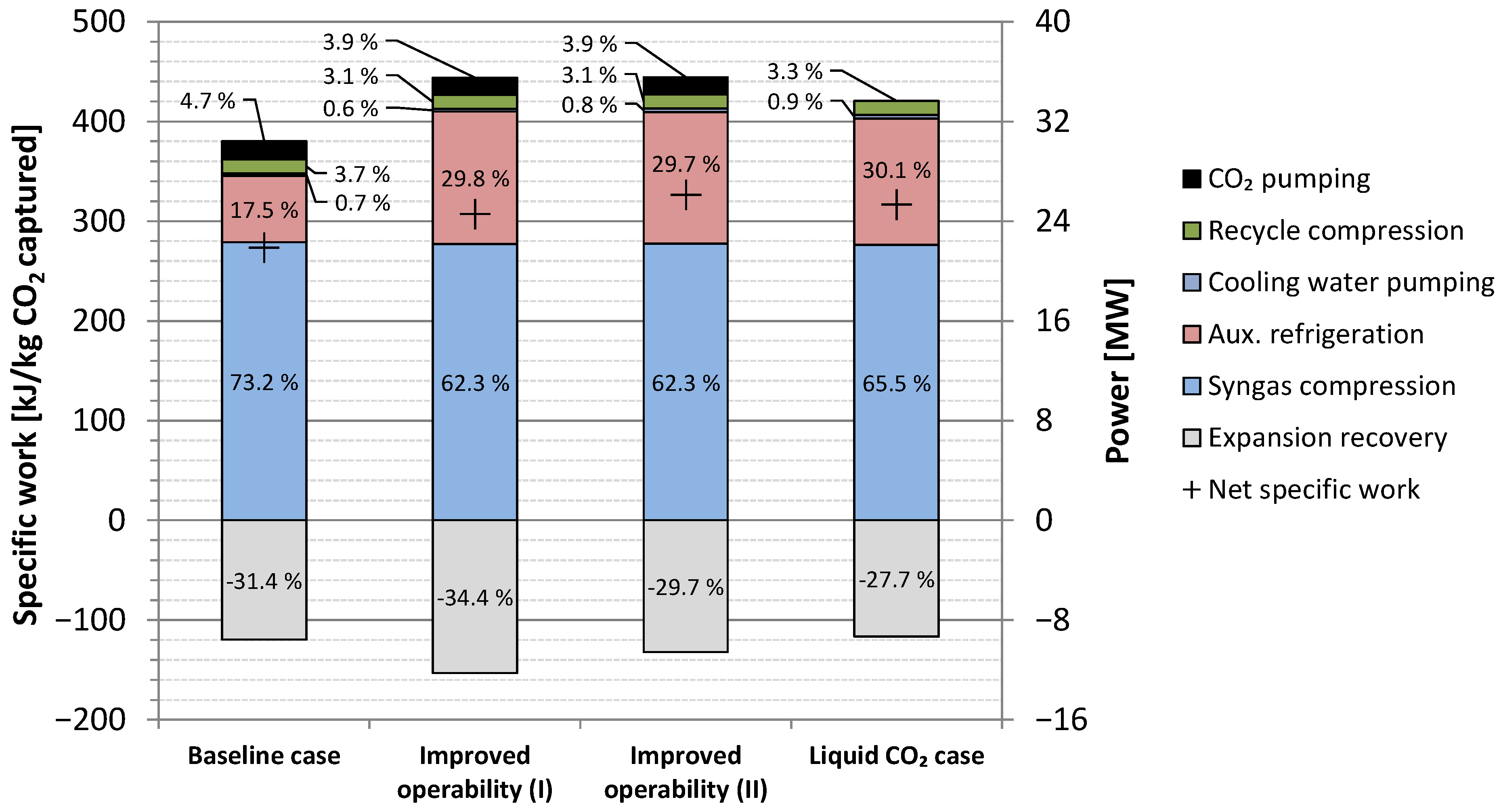
5.3. Results Summary

A comparison of the power requirements for the baseline case as well as the alternative schemes is given in Figure 15. For all considered cases, the dominant component with respect to power requirements is compression of the synthesis gas feed. The second dominant contribution is the power required by the auxiliary refrigeration cycles. As can be observed, the specific power requirements of the auxiliary refrigeration are larger in the cases for improved operability with high-temperature expanders, as well as for the liquid CO2 production case. In the cases for improved operability, the unutilised recuperative cooling potential of the expanded fuel stream leaves a considerable cooling duty deficit relative to the base case, which must be compensated by increased auxiliary refrigeration. Likewise, in the case of liquid CO2 for ship transport, the unutilised recuperative cooling potential of the liquid CO2 product leaves a cooling duty deficit. Compared to the baseline scheme, the increased auxiliary refrigeration duties result in higher net power input as well as specific CO2 separation work for all alternative process schemes. The net specific separation work in the liquid CO2 case is estimated to 317 kJe/kgCO2, which is approximately 16% higher than for the base case. As shown in Figure 15, the power recovery from expanding the hydrogen-rich fuel stream is significant and reduces the net power requirements substantially. The importance of use of expanders with respect to energy efficiency is evident as the net power requirements for the four different process schemes are reduced by 25–31% relative to gross power requirements without the expansion process.
Figure 16 displays a relative comparison of a selection of aggregate key results which can have implications for investment and operating cost for the different process schemes. The total swept volume, here defined as the sum of gas volumetric flowrates for compressor inlets and expander outlets, is considerably lower for the base case. For the improved-operability cases and liquid CO2 case the substantial increase in auxiliary cooling duty leads to 105% and 85% increase, respectively, in suction volumes in the R290 refrigeration cycle. This in turn corresponds to approximately 70% and 50% increase in total swept volume relative to the base case.
Although total heat exchanger duties are about 20% higher for the alternative cases, the sum of UA (product of overall heat transfer coefficient and heat transfer surface area) for all heat exchangers is about 20% lower. This is an indication that the total heat transfer surface area in the alternative cases is likely to be reduced relative to the base case.
As shown in Figure 15 and Figure 16 the net power requirements increase by 12–19% for the alternative cases, which contributes to increased energy cost. In the current analysis, these considerations are indicative only, and to further assess the cost trade-offs between compression capacity, heat transfer surface area and power requirement, detailed economic analyses are needed.

6. Conclusions

A process design was proposed for low-temperature CO2 capture from IGCC by condensation and phase separation. Steady-state simulations were carried out and the performance for the overall process as well as major process components and subsystems was investigated. For the most complex plate-fin heat exchangers, feasible geometric designs were developed and their results implemented in the overall process model.
The net specific power requirements for the base case were estimated to 273 kJe/kgCO2 at 85% CO2 capture ratio. The CO2 product from the base case configuration is high-pressure gas at 150 bar intended for pipeline transport. For the improved operability cases, which have less extensively heat-integrated configurations avoiding the most complex heat exchanger designs, the net power requirements increase by 12–19%. Another process configuration was designed for producing liquid CO2 at around 8 bar for ship transport. The net specific power requirements for this configuration are estimated to 317 kJe/kgCO2, corresponding to a 16% increase relative to the base case.
A sensitivity analysis for twelve different process parameters was performed with respect to the net power requirements of the capture unit. Results revealed that compressor and expander efficiencies and the minimum allowed temperature for synthesis gas separation are the parameters with highest impact, although this to a certain degree is like comparing “apples and oranges”. Findings from the sensitivity analysis reinforce the high importance of verifying turbomachinery efficiencies and CO2 freeze-out temperature for the synthesis gas mixtures.
Most input parameters for process unit performance used in this work, such as efficiencies for compressors and pressure drop and minimum temperature approach in heat exchangers, were specified rather conservatively. Hence, the results for power requirements should, therefore, be realistic. As an obvious example, detailed heat exchanger simulations based on a geometric model showed that the initially defined minimum temperature approach of 3 °C was by no means a limiting factor. Instead, the actual temperature approaches were considerably narrower and improved the internal heat recuperation.
Further work towards realisation of low-temperature CO2 capture from IGCC synthesis gas should be pursued both experimentally and modelling-wise. Experimental work should focus on the operational validation of the CO2 yield (CO2 capture ratio) and CO2 product purity achievable from CO2/H2-rich multicomponent gas mixtures. It should also include validation of the minimum feasible separation temperatures for avoiding CO2 freeze-out in the relevant synthesis gas mixtures at different pressure levels, and to what extent smaller fractions of dry ice can be tolerated in separators without causing disturbance or malfunction. Relevant results in this context are expected to become available from ongoing experimental activity in the project “MACH-2 – Membrane-Assisted CO2 capture through liquefaction for clean H2 production” [36], a spin-off project from NCCS Research Centre [37].

Author Contributions

Conceptualization, D.B., G.S., R.A., K.J. and P.N.; methodology, D.B., G.S., S.R., R.A., P.N. and S.T.; formal analysis, D.B., G.S., S.R. and R.A.; writing—original draft preparation, D.B., R.A. and S.R.; writing—review and editing, D.B., S.T., S.R., T.G.; project administration, S.T. All authors have read and agreed to the published version of the manuscript.

Funding

This publication was produced with support from the NCCS Research Centre, performed under the Norwegian research program Centres for Environment-friendly Energy Research (FME). The authors acknowledge the following partners for their contributions: Aker Solutions, Ansaldo Energia, Baker Hughes, CoorsTek Membrane Sciences, EMGS, Equinor, Gassco, Krohne, Larvik Shipping, Lundin, Norcem, Norwegian Oil and Gas, Quad Geometrics, Total, Vår Energi, and the Research Council of Norway (257579).

Conflicts of Interest

The authors declare no conflict of interest. The funders had no role in the design of the study; in the collection, analyses, or interpretation of data; in the writing of the manuscript, or in the decision to publish the results.

References

  1. Berstad, D.; Anantharaman, R.; Nekså, P. Low-temperature CO2 capture technologies—Applications and potential. Int. J. Refrig. 2013, 36, 1403–1416. [Google Scholar] [CrossRef]
  2. Nord, L.O.; Bolland, O. Plant flexibility of a pre-combustion CO2 capture cycle. Energy Procedia 2011, 4, 2556–2563. [Google Scholar] [CrossRef] [Green Version]
  3. Najmi, B.; Bolland, O. Operability of Integrated Gasification Combined Cycle power plant with SEWGS technology for pre-combustion CO2 capture. Energy Procedia 2014, 63, 1986–1995. [Google Scholar] [CrossRef] [Green Version]
  4. Moioli, S.; Giuffrida, A.; Romano, M.C.; Pellegrini, L.A.; Lozza, G. Assessment of MDEA absorption process for sequential H2S removal and CO2 capture in air-blown IGCC plants. Appl. Energy 2016, 183, 1452–1470. [Google Scholar] [CrossRef]
  5. Kunze, C.; Spliethoff, H. Assessment of oxy-fuel, pre- and post-combustion-based carbon capture for future IGCC plants. Appl. Energy 2012, 94, 109–116. [Google Scholar] [CrossRef]
  6. Melchior, T.; Madlener, R. Economic evaluation of IGCC plants with hot gas cleaning. Appl. Energy 2012, 97, 170–184. [Google Scholar] [CrossRef]
  7. Chen, S.; Xiang, W.; Wang, D.; Xue, Z. Incorporating IGCC and CaO sorption-enhanced process for power generation with CO2 capture. Appl. Energy 2012, 95, 285–294. [Google Scholar] [CrossRef]
  8. Franz, J.; Maas, P.; Scherer, V. Economic evaluation of pre-combustion CO2-capture in IGCC power plants by porous ceramic membranes. Appl. Energy 2014, 130, 532–542. [Google Scholar] [CrossRef]
  9. Ishii, H.; Hayashi, T.; Tada, H.; Yokohama, K.; Takashima, R.; Hayashi, J. Critical assessment of oxy-fuel integrated coal gasification combined cycles. Appl. Energy 2019, 233–234, 156–169. [Google Scholar] [CrossRef]
  10. Roussanaly, S.; Vitvarova, M.; Anantharaman, R.; Berstad, D.; Hagen, B.; Jakobsen, J.; Novotny, V.; Skaugen, G. Techno-economic comparison of three technologies for precombustion CO2 capture from a lignite-fired IGCC. Front. Chem. Sci. Eng. 2020, 14, 436–452. [Google Scholar] [CrossRef]
  11. Jordal, K.; Anantharaman, R.; Peters, T.A.; Berstad, D.; Morud, J.; Nekså, P.; Bredesen, R. High-Purity H2 Production with CO2 Capture Based on Coal Gasification. Energy 2015, 88, 9–17. [Google Scholar] [CrossRef] [Green Version]
  12. Consonni, S.; Viganò, F.; Kreutz, T.; De Lorenzo, L. CO2 Capture in IGCC Plants via Cryogenic Separation. In Proceedings of the Sixth Annual Conference on Carbon Capture & Sequestration, Pittsburgh, PA, USA, 7–10 May 2007. [Google Scholar]
  13. Brouwers, J.J.H.; van Kemenade, H.P. Condensed Rotational Separation for CO2 capture in coal gasification processes. In Proceedings of the 4th International Freiberg Conference on IGCC & XtL Technologies, Dresden, Germany, 3–6 May 2010; pp. 1–18. [Google Scholar]
  14. Berstad, D.; Anantharaman, R.; Nekså, P. Low-temperature CCS from an IGCC power plant and comparison with physical solvents. Energy Procedia 2013, 37, 2204–2211. [Google Scholar] [CrossRef] [Green Version]
  15. Berstad, D.; Roussanaly, S.; Skaugen, G.; Anantharaman, R.; Nekså, P.; Jordal, K. Energy and Cost Evaluation of a Low-temperature CO2 Capture Unit for IGCC plants. Energy Procedia 2014, 63, 2031–2036. [Google Scholar] [CrossRef] [Green Version]
  16. Peampermpool, R.; Teh, C.J.; Tade, M.; Qader, A.; Barifcani, A. More Energy-Efficient CO2 Capture from IGCC GE Flue Gases. C 2017, 3, 7. [Google Scholar] [CrossRef] [Green Version]
  17. Mori, Y.; Forsyth, J. High Performance CO2 Capture by Autothermal AGR. Energy Procedia 2013, 37, 2284–2292. [Google Scholar] [CrossRef] [Green Version]
  18. Kim, D.; Berstad, D.; Anantharaman, R.; Straus, J.; Peters, T.A.; Gundersen, T. Low Temperature Applications for CO2 Capture in Hydrogen Production. Comput. Aided Chem. Eng. 2020, 48, 445–450. [Google Scholar] [CrossRef]
  19. Intergovernmental Panel on Climate Change. Carbon Capture and Storage; Special Report of the IPCC; Cambridge University Press: Cambridge, UK, 2005; p. 404. [Google Scholar]
  20. International Institute of Refrigeration. International Dictionary of Refrigeration; Peeters Publishers: Leuven, Belgium, 2007. [Google Scholar]
  21. Tuinier, M.; van Sint Annaland, M.; Kramer, G.J.; Kuipers, J. Cryogenic CO2 capture using dynamically operated packed beds. Chem. Eng. Sci. 2010, 65, 114–119. [Google Scholar] [CrossRef]
  22. Berger, A.H.; Hoeger, C.; Baxter, L.; Bhown, A. Evaluation of Cryogenic Systems for Post Combustion CO2 Capture. In Proceedings of the 14th Greenhouse Gas Control Technologies Conference (GHGT-14), Melbourne, Australia, 21–26 October 2018. [Google Scholar]
  23. Anantharaman, R.; Bolland, O.; Booth, N.; Dorst, E.V.; Ekstrom, C.; Franco, F.; Macchi, E.; Manzolini, G.; Nikolic, D.; Pfeffer, A.; et al. D1.4.3 European best practice guidelines for assessment of CO2 capture technologies. DECARBit 2011. Available online: https://www.sintef.no/globalassets/project/decarbit/d-1-4-3_euro_bp_guid_for_ass_co2_cap_tech_280211.pdf (accessed on 21 October 2021).
  24. Li, H.; Dong, B.; Yu, Z.; Yan, J.; Zhu, K. Thermo-physical properties of CO2 mixtures and their impacts on CO2 capture, transport and storage: Progress since 2011. Appl. Energy 2019, 255, 113789. [Google Scholar] [CrossRef]
  25. Spano, J.O.; Heck, C.K.; Barrick, P.L. Liquid-vapor equilibria of the hydrogen-carbon dioxide system. J. Chem. Eng. Data 1968, 13, 168–171. [Google Scholar] [CrossRef]
  26. Tsang, C.Y.; Streett, W.B. Phase equilibria in the H2/CO2 system at temperatures from 220 to 290 K and pressures to 172 MPa. Chem. Eng. Sci. 1981, 36, 993–1000. [Google Scholar] [CrossRef]
  27. Bezanehtak, K.; Combes, G.B.; Dehghani, F.; Foster, N.R.; Tomasko, D.L. Vapor−Liquid Equilibrium for Binary Systems of Carbon Dioxide + Methanol, Hydrogen + Methanol, and Hydrogen + Carbon Dioxide at High Pressures. J. Chem. Eng. Data 2002, 47, 161–168. [Google Scholar] [CrossRef]
  28. Qian, J.-W.; Jaubert, J.-N.; Privat, R. Phase equilibria in hydrogen-containing binary systems modeled with the Peng–Robinson equation of state and temperature-dependent binary interaction parameters calculated through a group-contribution method. J. Supercrit. Fluids 2013, 75, 58–71. [Google Scholar] [CrossRef]
  29. Fandiño, O.; Martin Trusler, J.P.; Vega-Maza, D. Phase behavior of (CO2 + H2) and (CO2 + N2) at temperatures between (218.15 and 303.15) K at pressures up to 15 MPa. Int. J. Greenh. Gas Control 2015, 36, 78–92. [Google Scholar] [CrossRef] [Green Version]
  30. Trædal, S.; Berstad, D.; Stang, J. Experimental Investigation of Low Temperature CO2 Liquefaction and Phase-Separation for Carbon Capture. Refrig. Sci. Technol. 2019, F147717, 147–153. [Google Scholar]
  31. Wu, H.; Xu, M.; Li, Y.; Wu, J.; Shen, J.; Liao, H. Experimental research on the process of compression and purification of CO2 in oxy-fuel combustion. Appl. Energy 2020, 259, 114123. [Google Scholar] [CrossRef]
  32. Wexler, A. Vapor Pressure Formulation for Ice. J. Res. Natl. Bur. Stand. 1977, 81A, 5–20. [Google Scholar] [CrossRef]
  33. ALPEMA. The Standards of the Brazed Aluminium Plate-Fin Heat Exchanger Manufacturers’ Association, 2nd ed.; ALPEMA: Houston, TX, USA, 2000. [Google Scholar]
  34. Bischoff, S.; Decker, L. First operating results of a dynamic gas bearing turbine in an industrial hydrogen liquefier. In Proceedings of the Advances in Cryogenic Engineering: Transactions of the Cryogenic Engineering Conference, Hong Kong, China, 17–19 March 2010. [Google Scholar]
  35. Roussanaly, S.; Bureau-Cauchois, G.; Husebye, J. Costs benchmark of CO2 transport technologies for a group of various size industries. Int. J. Greenh. Gas Control 2013, 12C, 341–350. [Google Scholar] [CrossRef] [Green Version]
  36. MACH-2—Membrane-Assisted CO2 Capture through Liquefaction for Clean H2 Production. Available online: https://www.sintef.no/en/projects/2019/mach-2-membrane-assisted-co2-capture-through-liquefaction-for-clean-h2-production/ (accessed on 19 November 2021).
  37. NCCS—Norwegian CCS Research Centre. Available online: https://www.sintef.no/nccs/ (accessed on 19 November 2021).
Figure 1. Block diagram of the integrated gasification combined cycle with low-temperature CO2 capture.
Energies 15 00515 g001
Figure 2. Vapour–liquid equilibrium data for a binary H2/CO2 system. The plot is based on experimental data from [26], indicated with circular markers and dotted black lines, and [29], indicated with diamond markers and solid red lines.
Energies 15 00515 g002
Figure 3. Phase separation of partially condensed syngas mixture. fCO2, xCO2 and yCO2 denote mole fractions of CO2 in the feed, liquid product and vapour product, respectively.
Energies 15 00515 g003
Figure 4. Estimated CO2 capture ratio for phase separation of a binary H2/CO2 mixture.
Energies 15 00515 g004
Figure 5. Estimated CCR for binary and actual syngas mixtures with approximately 38 mol% CO2.
Energies 15 00515 g005
Figure 6. Baseline process design for the low-temperature CO2 capture unit.
Energies 15 00515 g006
Figure 7. Heat exchanger HX2a (generated in Aspen MULE).
Energies 15 00515 g007
Figure 8. Temperature profiles for plate-fin heat exchanger HX2a.
Energies 15 00515 g008
Figure 9. Temperature profiles for plate-fin heat exchanger HX1.
Energies 15 00515 g009
Figure 10. Temperature profiles for plate-fin heat exchanger HX2b.
Energies 15 00515 g010
Figure 11. Basic layout of the auxiliary propane/ethane (R290/R170) cascade refrigeration cycle.
Energies 15 00515 g011
Figure 12. Process flow diagram with high-temperature expanders for improved operability.
Energies 15 00515 g012
Figure 13. Process flow diagram for the low-temperature capture unit producing liquid CO2 for ship transport.
Energies 15 00515 g013
Figure 14. Results from the sensitivity analysis for specific power requirements. The legends rank the slope of curves in descending order. Supplementary data on axis values are given in Table 5.
Energies 15 00515 g014
Figure 15. Power figures for the baseline case, improved operability cases and liquid CO2 case for ship transport. The percentage of each power component relative to the gross power requirement for each case is also shown.
Energies 15 00515 g015
Figure 16. Comparison of relative values for the four different cases. Base case is defined as reference point (100%) for all categories.
Energies 15 00515 g016
Table 1. Normalised synthesis gas key component fractions after desulphurisation and dehydration.
ComponentH2CO2CON2Ar
Mole fraction0.53750.38040.01600.05710.0090
Table 2. Summary of heat exchanger simulations.
UnitDuty MWLMTD °CUA kJ/(K·s)
HX19.102.553571
HX2a16.14.373683
HX2b7.015.021396
HX31.954.44438.3
HX42.366.74350.0
HX56.537.90826.8
Table 3. Summary of rotating equipment in the low-temperature capture unit.
Shaft Power MWIsentropic Efficiency %Volumetric Flowrate m3/hPressure RatioMolar Mass g/mol
Syngas compressor, 1st stage11.68515,0001.8520.9
Syngas compressor, 2nd stage10.88278001.7720.9
Recycle compressor1.128023004.5534.2
LP R290 compressor1.778541,0003.4144.1
HP R290 compressor2.758519,0003.5144.1
R170 compressor0.907576002.1830.1
LT CO2 pump0.718025011.544.0
HT CO2 pump0.74803501.7144.0
Fuel expander, 1st stage4.74854600 12.098.85
Fuel expander, 2nd stage4.86889600 12.078.85
Syngas compressor, 1st stage11.68515,0001.8520.9
1 At outlet.
Table 4. Power results for the baseline low-temperature CO2 capture unit.
ItemUnitValue
Syngas compressionMWe22.39
Auxiliary refrigerationMWe5.341
Cooling water pumpingMWe0.203
Recycle compressionMWe1.123
CO2 pumpingMWe1.445
Hydrogen loss 1MWe0.081
Fuel expanders 2MWe8.639
Net power requirementMWe21.94
Specific power requirementkJe/kg CO2 captured273.4
1 Power loss defined as 40% of lost hydrogen energy flow on an LHV basis. 2 Available electric power from turbine generators.
Table 5. Parameter descriptions for the sensitivity analysis.
ParameterUnitBaseline Value 1Unit on X-Axis 1
Separation temperature°C−561 °C
Isentropic efficiency (vector)%See Table 3(−1)%-points
R290 evaporation pressurebar1.0150.1 bar
HX2 minimum temperature approach°C31 °C
Intercooler outlet temperature°C301 °C
Low-temperature HX pressure dropbar0.5; 1.0 20.1 bar
Mech.-to-electrical conversion efficiency%90(−1)%-points
Intercooler pressure dropbar0.50.1 bar
Temperature difference in R290/R170 HX°C51 °C
R290/R170 subcooling (∆) temperature°C31 °C
Specific cooling water pumping powerkWel/MWth51 kWel/MWth
R290/R170 superheat (∆) temperature°C31 °C
1 Refers to Figure 14. 2 For liquid CO2 streams.
Publisher’s Note: MDPI stays neutral with regard to jurisdictional claims in published maps and institutional affiliations.

