Article

Grid-like Vibration Measurements on Power Transformer Tank during Open-Circuit and Short-Circuit Tests

1
Končar-Electrical Engineering Institute Ltd., 10002 Zagreb, Croatia
2
Faculty of Electrical Engineering and Computing, University of Zagreb, 10000 Zagreb, Croatia
*
Author to whom correspondence should be addressed.
Energies 2022, 15(2), 492; https://doi.org/10.3390/en15020492
Submission received: 3 December 2021 / Revised: 3 January 2022 / Accepted: 6 January 2022 / Published: 11 January 2022

Abstract

:
In this work, the vibrations on the surfaces of the tank wall, stiffeners, and the cover of a 5 MVA transformer experimental model were measured during open-circuit and short-circuit transformer tests. Vibration measurements of a transformer tank side were conducted at discrete points using two different voltage sources in no-load test. Using interpolation functions, the RMS values of acceleration and vibration velocity are visualized and compared for each considered measurement configuration (no-load and load tests and two different excitation sources). Significant differences in mode shapes and amplitudes of vibrations at different frequencies are observed. The maximum RMS values of acceleration, velocity and displacement in the open-circuit test are 0.36 m/s2, 0.31 mm/s, and 0.42 µm, respectively. The maximum values in short-circuit test are 0.74 m/s2, 1.14 mm/s, and 1.8 µm, respectively. In the short-circuit test, the frequency component of 100 Hz is dominant. In the open-circuit test, the first few 100 Hz harmonics are significant (100 Hz, 200 Hz, and 300 Hz). In addition to the visualization of RMS values during the open-circuit and short-circuit tests, animations of the vibrations are created. Fourier analysis and phase comparison between frequency components are also used to show vibration animations at dominant frequencies in the spectrum (100 Hz harmonics). The visualization of the vibrations at the tank wall surfaces is transferred into 3D space in such a way that all 15 surfaces are mapped to the spatial coordinates of the surfaces so that a 3D model of the acceleration, vibration velocity, and displacement of the transformer tank is shown.

Graphical Abstract

1. Introduction

Transformer vibrations and consequently its noise are becoming an increasing problem as transformers are more often located near populated areas, especially large cities. Local noise regulations, more stringent standards and new design requirements force manufacturers to design very low noise transformers [1]. Therefore, understanding the physics of vibration, the origin and propagation of noise, and the response of human hearing to a different frequency spectrum of noise is nowadays becoming more crucial.
The primary sources of vibration in transformers are the windings and the core. Due to the oil’s negligible compressibility, the sound pressure generated by the vibrations from the internal sources is transmitted to the tank surfaces through the transformer oil almost without any damping. The second transmission path for vibrations is through mechanical connections between the core and the tank [2]. The tank responds to these pressure fluctuations and mechanical waves depending on its natural frequencies and vibrational mode shapes.
Transformer manufacturers test the noise response from transformer windings and core separately in open-circuit or no-load and short-circuit or load tests according to standards [3,4]. In the transformer load test, double the network frequency (100 or 120 Hz) is dominant due to excitation by electromagnetic forces between windings. The windings have approximately linear vibration characteristics so that higher harmonics are not excited. In the no-load test, due to the nonlinear saturation characteristic of the core, magnetostriction forces excite the core’s magnetic sheet vibrations at even harmonics of the network frequency (100 Hz, 200 Hz, 300 Hz, and 400 Hz) [5].
In the literature [2,6,7], the transmission of the vibrations from the internal structure (transformer active part) to the transformer tank is studied. The experiments on the 110 kV power transformer with and without cooling oil are carried out in the paper [2]. The mechanical excitation in this experimental setup is a large impact hammer that excites the accelerometers, and thus the frequency response functions are obtained. The cooling oil adds a transmission path that amplifies the tank vibrations but also increases the mass and damping, resulting in a reduction of the vibrations. The significant vibration harmonics of the transformer tank are not necessarily due to the intense vibrations of the excitation, but a relatively high magnitude of transmission response at these harmonic frequencies might be a cause. The paper [7] reports an investigation on the internal vibration source of power transformer through experimental modal analysis of the windings. The conclusions state that the winding vibrations are strongly coupled with the core vibrations, but the core vibrations are hardly affected by the winding vibrations. Another finding was that the winding vibrations are mainly transmitted to the tank through the oil.
The transformer tank surface vibration distribution patterns (vibration mapping) are measured and visualized in the literature [8,9,10,11,12,13,14]. In papers [8,9], the velocity of the tank surface is measured using a laser Doppler vibrometer. Small changes in the mechanical structure caused changes in the phase and amplitude of the involved resonant modes, resulting in different vibration patterns [8]. In [9], vibroacoustic analysis of a small power transformer is carried out, and visualization of the RMS values of the vibration velocity on the transformer tank in all directions is presented. In [11], vibration signals and voltage signals at each measurement point on the transformer surface are measured simultaneously so that the signals of all points can be calibrated by correcting the phase with a voltage as a reference signal. The spatial distribution of the vibration velocity on each surface of the transformer tank at the first three dominant frequencies (100 Hz, 200 Hz, and 300 Hz) is shown. The maximum vibration amplitude positions at different frequencies are different. In the literature [13], the excitation voltage signal is also used as a reference signal to calibrate the measured signal at all points on the tank. The overall vibration patterns and the patterns at different frequencies at a tank surface are shown. The vibration patterns are compared when the load and clamping pressure are changed and after several short circuit events. An image feature Histogram of Oriented Gradient (HOG) is used to evaluate the differences which can be used in transformer monitoring. In [14], vibration distribution patterns of the tank under different winding defects and loads are shown, and the detection of transformer winding faults based on these patterns is discussed. The authors of the paper [15] used a three-axis piezoelectric accelerometer to test a 1 MVA, 10/0.4 kV transformer. The vibrations on all considered surfaces of the tank are mainly in the direction normal to the surface.
This study pointed out the importance of voltage source selection and its influence on vibration distribution patterns, total vibration values, and values at specific frequency components. The visualization of the measurement results is provided using Matlab interpolation function interp2. The authors in [9] measured and visualized the vibrations in all three axes, while this work only provides measurements normal to the surface. As shown in [15], the normal component is dominant and generally contributes the most to the emitted noise. Therefore, more expensive three-axis accelerometers are usually not necessary for such measurements. In [11,13], the authors used a voltage signal to align the vibration signals, but the vibration of the transformer tank in 3D space and the instantaneous amplitudes of the vibrations in the time domain are not presented. Compared to other research in the field, the contribution of this study is in providing a developed and defined method for vibration visualization at the entire transformer surface in spatial coordinates, including stiffeners and cover if necessary. This includes RMS values and instantaneous values of the total signal or at specific frequencies of vibration acceleration, velocity, and displacement. The method is robust and adaptable for different transformer geometries. This provides a stable and reliable basis for future applications mentioned later in the paper.

2. Theoretical Considerations

In this section, the basic theory of propagation of sound waves in solid plates, natural modes, and natural frequencies of the plate, as well as the analytical determination of sound pressure at some point in space away from the transformer using measured vibration velocity magnitudes and distribution at the transformer tank, is presented.
As this work is based on vibration measurement and visualization on the transformer tank, the theory of sound excitation and propagation inside the transformer tank (from the active part to the tank) is not considered. In other words, the complex geometry and physics of the transformer core and the windings are observed as a black box in this work. Significant work in numerical modeling of transformer core and windings with limitations and simplifications is presented in [16,17,18,19,20,21]. The goal of this paper is to provide a physical background and visualize vibrations to be able to compare transformer vibration response at different conditions, estimate sound pressure levels around the transformer, and give a solid basis for the future verification of numerical modeling.

2.1. Propagation of Sound Waves in Solid Plates

Except for longitudinal waves present in the fluids, shear waves and a combination of these two basic wave types are present in solid materials. The most important combined wave type is the bending wave. Combined waves are created at the boundaries where coupling and transformation from one basic wave type to another occur. Bending waves can very efficiently radiate sound to the surrounding air. The reason for that is transverse motion which has low impedance, and the frequency dependency of the wave speed. Bending wave typical for thin plates and long wavelengths is controlled with the bending wave equation [22]:
E h 3 12 ( 1 μ 2 )   4 v x 4 + ρ h 2 v t 2 = 0
where ρ is the density of plate material, h is a plate thickness, E is the Young modulus, and µ is the Poisson ratio. The wave speed of the bending wave is the frequency-dependent and given by [22]:
c B = ω B / m 4 = 2 π f     E h 2 / ( 12 ρ ( 1 μ 2 ) ) 4
Shear wave is the transversal wave in which the sections of a plate are shifted in parallel, perpendicular to the direction of propagation. The speed of the shear wave is [22]:
c s = G ρ = E 2 ρ ( 1 + μ )           [ m s ]
The critical frequency fc is the frequency where the bending wave speed is equal to the acoustic wave speed in the air (cB = c = 344 m/s). The same speed and wavelength cause good coupling between these two wave types, which means that the plate efficiently radiates sound at and above this frequency. From Equation (2), it follows that:
f c = c 2 π h 3 ρ ( 1 μ 2 ) E = K c h
where Kc is the material constant. Increasing the frequency of the wave propagation, there is a gradual transition from bending to shear wave. The crossover frequency fs is defined when bending wave speed cB becomes equal to the shear wave speed cS. By equalization of the Equations (2) and (3), the crossover frequency is equal to:
f s = 1 2 π h 3 E ( 1 μ ) ρ ( 1 + μ )
The critical and crossover frequencies for considered tank wall plate thickness of the transformer experimental model are shown in Section 4.3.

2.2. Normal Modes and Natural Frequencies of a Plate

Forced vibrations of the plate are the vibrations caused directly due to the surrounding sound field exciting the plate. Resonant vibrations are the free vibrations caused by reflections of the forced vibrations from the boundaries. Normal modes are the free vibration patterns in a finite system without excitation. They are responsible for building up the field when the excitation starts. Each normal mode has its own natural or resonance frequency and a modal amplitude. Normal modes should fulfill the bending wave Equation (1) for a plate geometry in the low-frequency region below the crossover frequency.
The displacement and the moment reaction of a simply supported rectangular plate at the boundary are zero, but the rotational movement is free. Moment reaction is related to the second derivative of the displacement field, so modes need to have zero value at the boundary, and the second-order derivative should also be zero. To fulfill these conditions bending wave equation functions sin(kxx) in the x-direction and sin(kyy) in the y-direction are used [22]. If there are simple supports at x = 0, x = lx, y = 0, and y = ly, the wavenumber k must be equal to:
k x , m = m π / l x
k y , n = n π / l y
where m and n are arbitrary integers, lx is the length of the plate in the x-direction, and ly is the length of the plate in the y-direction.
Considering that, a normal mode can be written as:
ϕ m , n ( x , y ) = sin ( m π l x x ) sin ( n π l y y )
Using the Pythagoras relationship between the free bending wavenumbers kB and the mode numbers m and n and replacing bending wavenumber with the expression with the bending wavelength λB, the following expression is obtained:
k b 2 = ( 2 π λ B ) 2 = k m , x 2 + k n , y 2 = ( m π l x ) 2 + ( n π l y ) 2
At low frequencies, where bending waves are assumed, the wavelength of the panel is:
λ B = c B / f = c / f · f c
Inserting Equation (10) into Equation (9), the natural frequency of the mode with numbers (m, n) is:
f m , n = c 2 4 f c ( ( m l x ) 2 + ( n l y ) 2 )
The natural frequencies and the modes for considered dimensions of transformer experimental model tank wall plates are shown in Section 4.3.

2.3. Analytical Determination of Sound Pressure in the Point Away from the Plane with Measured Vibration Velocity Distribution Considering Incoherent Plane Radiation

Radiated power of the piston source in the near field as it is investigated in [23] is:
W = 1 / 2 · ρ c R R π a 2 U 2
where ρ is the air density, c is the speed of sound in air, ρcπa2RR is the real part of the radiation impedance. Estimation of sound power that machines are radiating in operation when their surface is vibrating can be determined by the mean square vibration velocity averaged over the surface [24]. Replacing U2/2 from Equation (12) with the surface mean square velocity < v2 > S,t, replacing the piston surface area πa2 with the plate surface S, and RR with surface radiation efficiency σ, Equation (12) becomes:
W = v 2 S , t S ρ c σ
Dividing Equation (13) by Wref = 10−12 W, taking logarithms to the base 10, multiplying by 10 of both sides of the equation, and including values for air density ρ and speed of sound in air c into the equation, gives the following expression:
L W = 10 log 10 v 2 S , t + 10 log 10 S + 10 log 10 σ + 146   ( d B   r e   10 12   W )
The radiation efficiency of steel flat panels can be extracted from the curves of the radiation efficiency of steel and aluminum flat panels [25] or expression derived in [26] used for the case of resonant vibrations in a plate generated by random incidence sound for the frequencies below the critical frequency. In the literature [27], the sound radiation efficiency is calculated using a validated BEM model. It is concluded that radiation efficiency is higher at high frequencies than at low frequencies and that narrow plate spacing of radiator structure reduces the radiation efficiency at low frequencies. For more precise calculations, those findings can also be considered.
Following the above-explained procedures, measured octave or 1/3 octave spectrum of the surface mean square vibration velocity of a plate can be used to calculate radiated power of a plate. Radiation of a plane distribution of incoherent radiators is considered in [28], where cosine weighting on the radiation directivity of an elementary source is used. It does not satisfy the wave equation, but it greatly simplifies the integration and provides better results than an analysis based on unweighted sources.
The vibration measured at all surfaces of the transformer will be used in future work to calculate total sound pressure from each transformer side, including contributions of all neighboring surfaces, and those results will be compared with the sound pressure measurements.

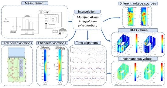
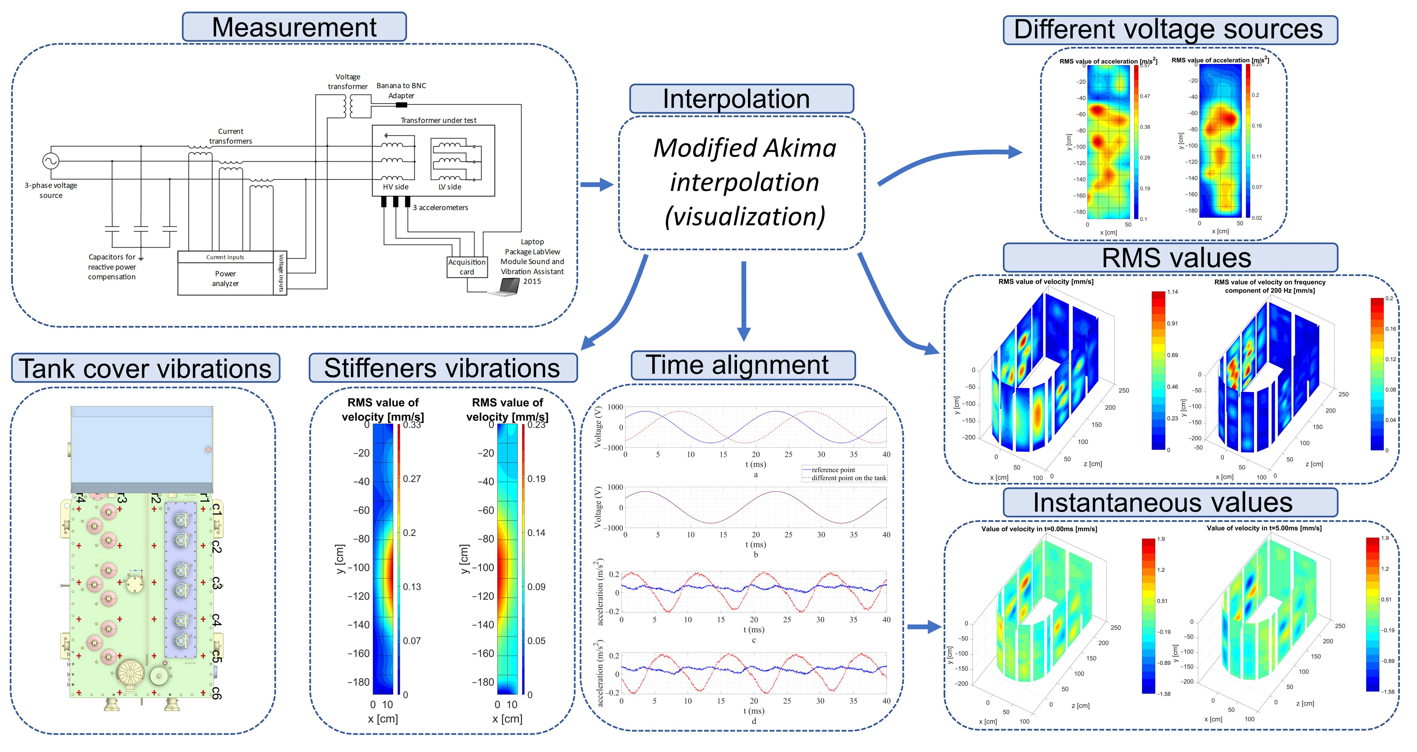
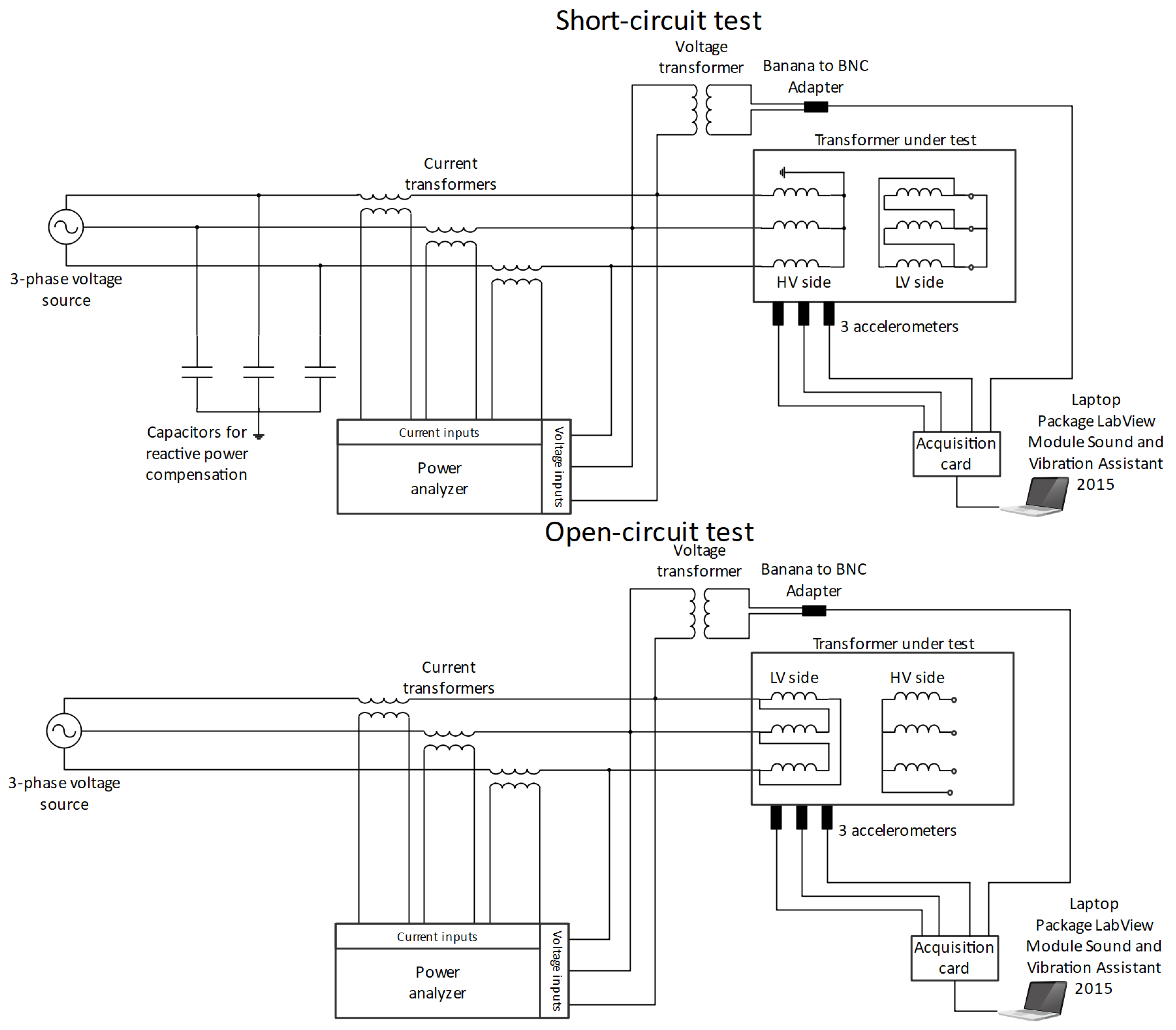
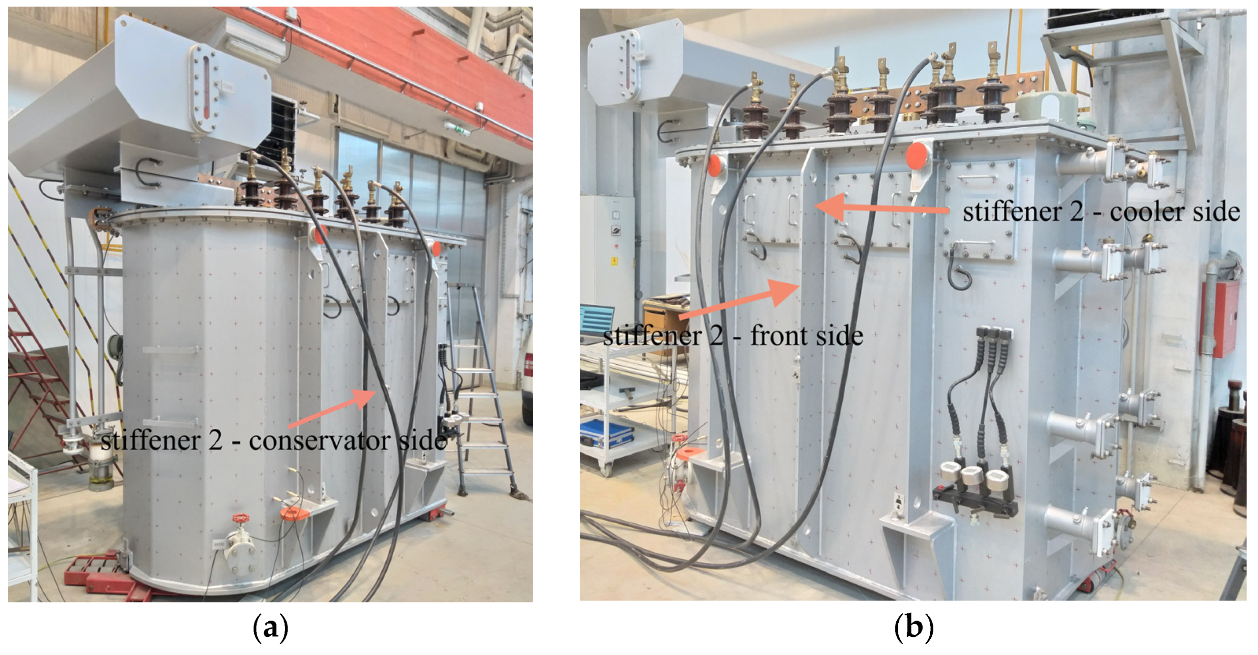
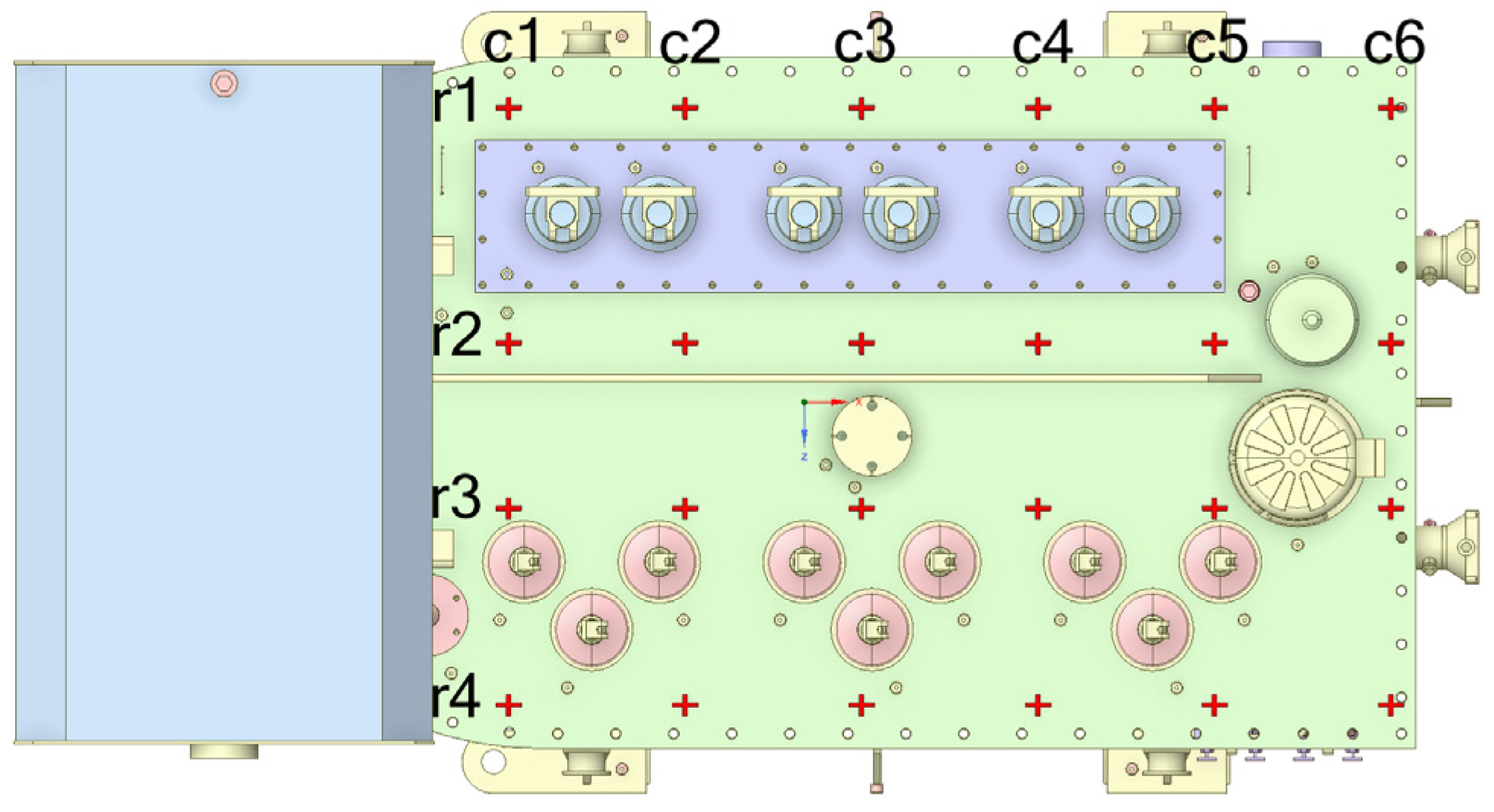
3. Measurement Setup

For vibration measurement, three accelerometers PCB Piezotronics 608A11 with specifications listed in Table 1 are used in this paper.
The acquisition card consisted of the chassis NI cDAQ-9171 and the module NI-9234 with four analog inputs and an AC voltage range of ±5.1 Vpk. Accelerometers are calibrated with the calibrator B&K type 4294. Software used for measurements is LabVIEW with the software module Sound and Vibration Assistant 2015. Three accelerometers and voltage signals from the instrument transformer are connected to the acquisition card connected to the laptop with installed LabVIEW software. Accelerometers measure only acceleration components normal to the surface.
Except for the vibration measurement setup diagram, the electrical diagrams in short-circuit and open-circuit tests are also shown in Figure 1. Current transformers lower the current for measurement on the power analyzer. The voltage is measured directly. A voltage instrument transformer lowers the voltage to measure and record the signal using an acquisition card. In the short-circuit test, the transformer is powered from the high voltage (HV) side, and the low voltage (LV) side is short-circuited. In the open-circuit test, the transformer is powered from the LV side, and HV terminals remain open.
Vibrations are measured on the surfaces of the tank wall, stiffeners, and cover of the 5 MVA transformer experimental model. The measurements on the transformer tank wall are shown in Figure 2a. The transformer surfaces are numbered for more straightforward measurement and better results representations, as shown in Figure 2b.
Figure 3 shows that at the open-circuit test for the first three most significant harmonics of double the network frequency (100 Hz, 200 Hz, 300 Hz), SNR is over 30 dB. For the frequencies at which the signal component is negligible, SNR is much smaller. The values go down to −20 dB, representing that the noise has much higher values than the signal.
For visualization of time-dependent vibrations, all vibration signals should be measured simultaneously. As only four analog inputs are available, the input line voltage signal is used to align all the measurements as if they are measured simultaneously, as in papers [11,13]. Voltage signals of every measurement are aligned, and acceleration signals are translated for the same time frame, as is shown in Figure 4.

4. Results

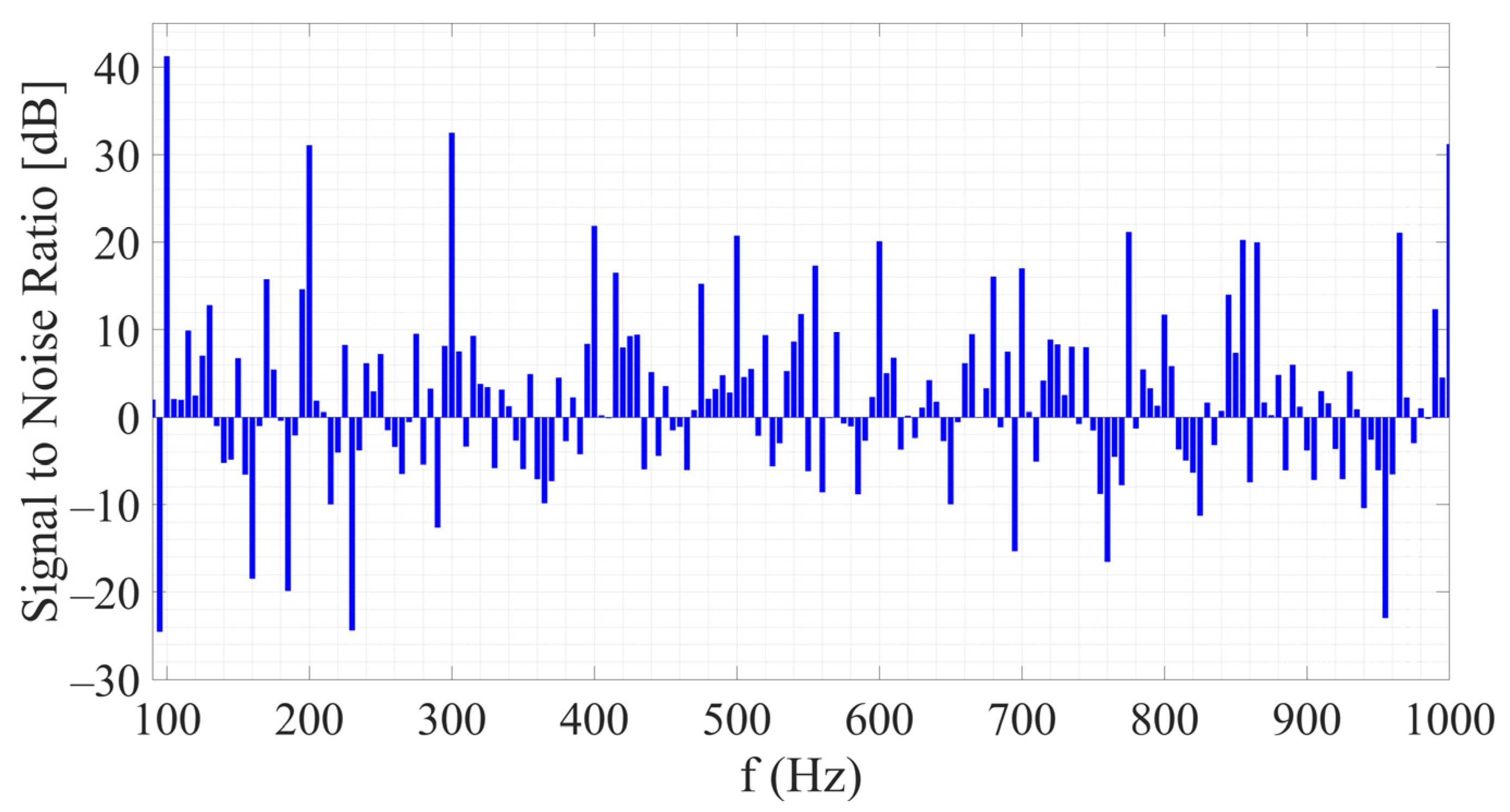
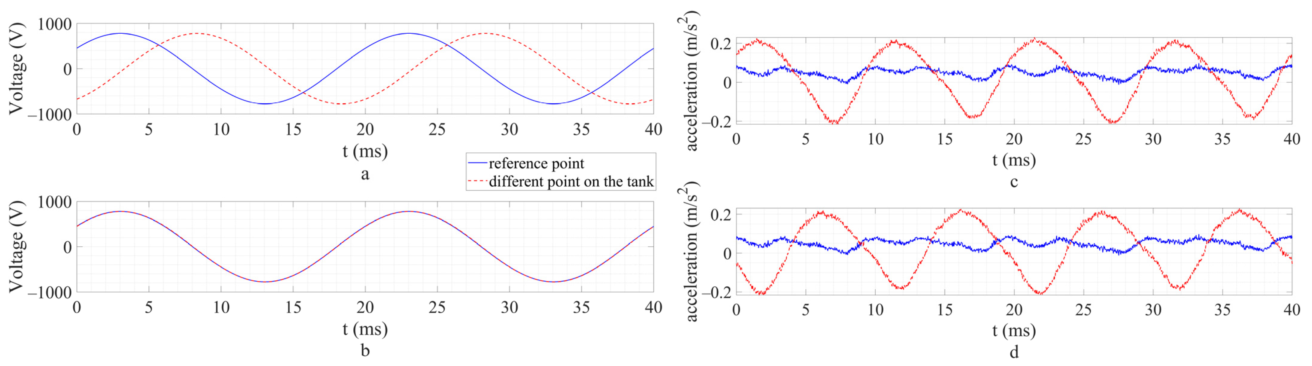
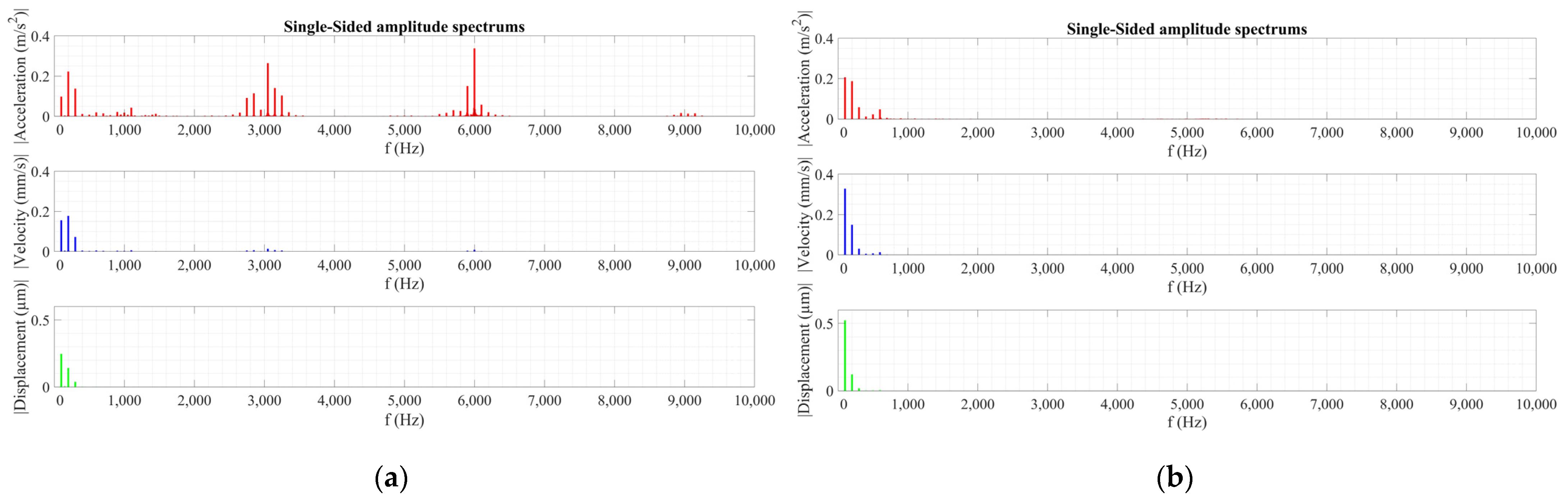
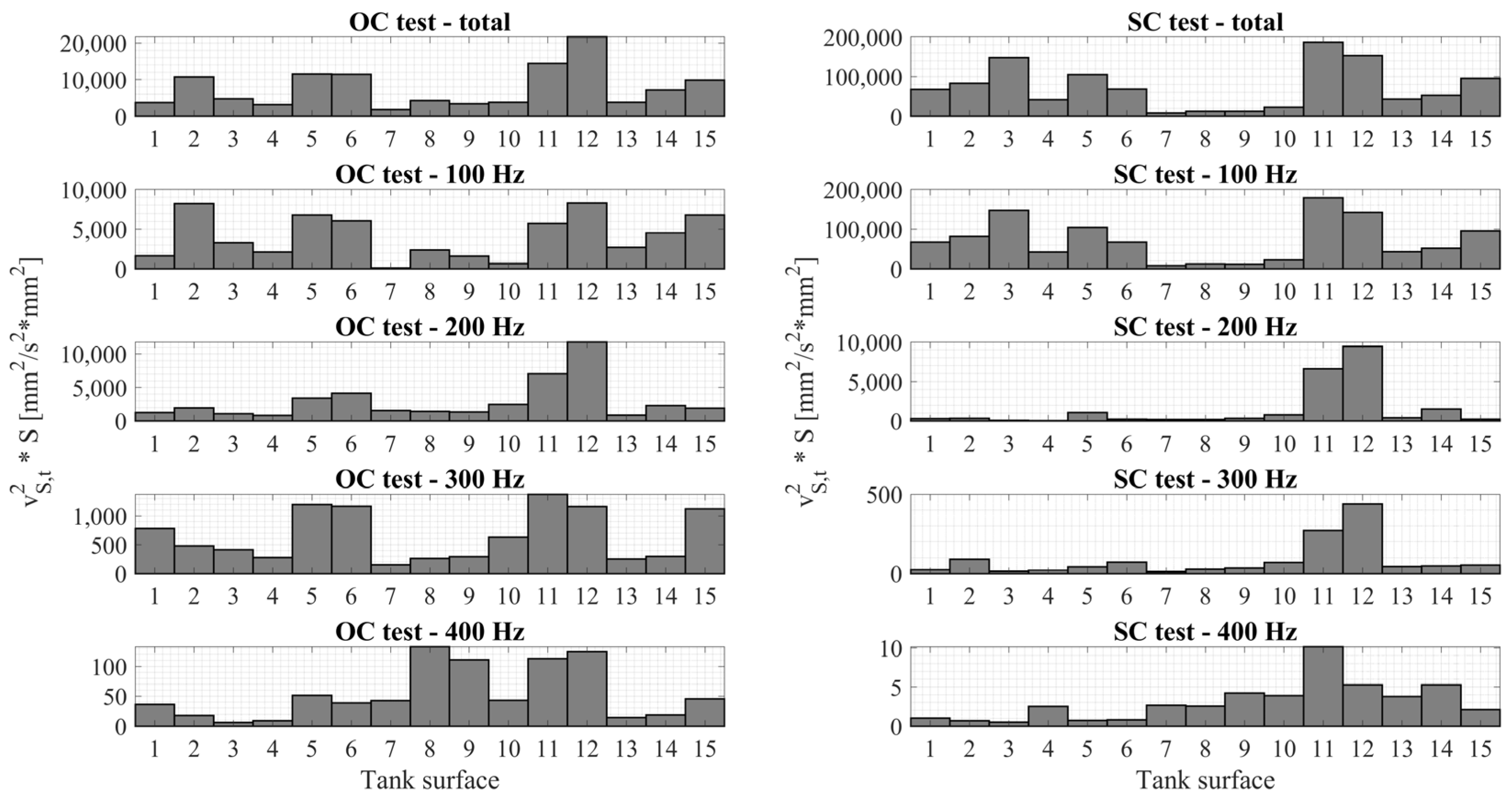
4.1. Comparison of the Vibration Measurements Using Two Different Voltage Sources

Comparison of vibrations using two different voltage sources is made during transformer open-circuit test. One of the sources was a power converter (output power: 120 kVA; output voltage range: 3 × (100–700 V); output frequency range: 45–65 Hz; output current range: 0–100 AACRMS; THD: <3% over the whole range) that had significant voltage harmonics at 3 kHz, 6 kHz, and 9 kHz, as can be seen in Figure 5a. These were more prominent for higher voltages when the transformer core was close to saturation because of the nonlinearity of the B-H curve, which caused higher current harmonics. In addition, due to relatively low output power of the source, voltage distortion occurred, and the voltage harmonics appeared depending on the source characteristics (converters inside the source). Due to higher voltage harmonics, the transformer is tested at only 90% of its nominal voltage (the nominal voltage is 10 kV at the HV side and 0.4 kV at the LV side). Consequently, higher excitation voltage harmonics caused high vibration components of 3 kHz and 6 kHz, as shown in Figure 6a.
The second voltage source was regulating transformer (rated power: 500 kVA; rated output voltage: 0–420 V; frequency: 50 Hz; rated output current: 687 A) that had approximately sinusoidal voltage, as shown in Figure 5b, and there are no higher frequency components of tank vibrations as visible in Figure 6b. Figure 5 and Figure 6 represent measurements for a point on the transformer surface 5.

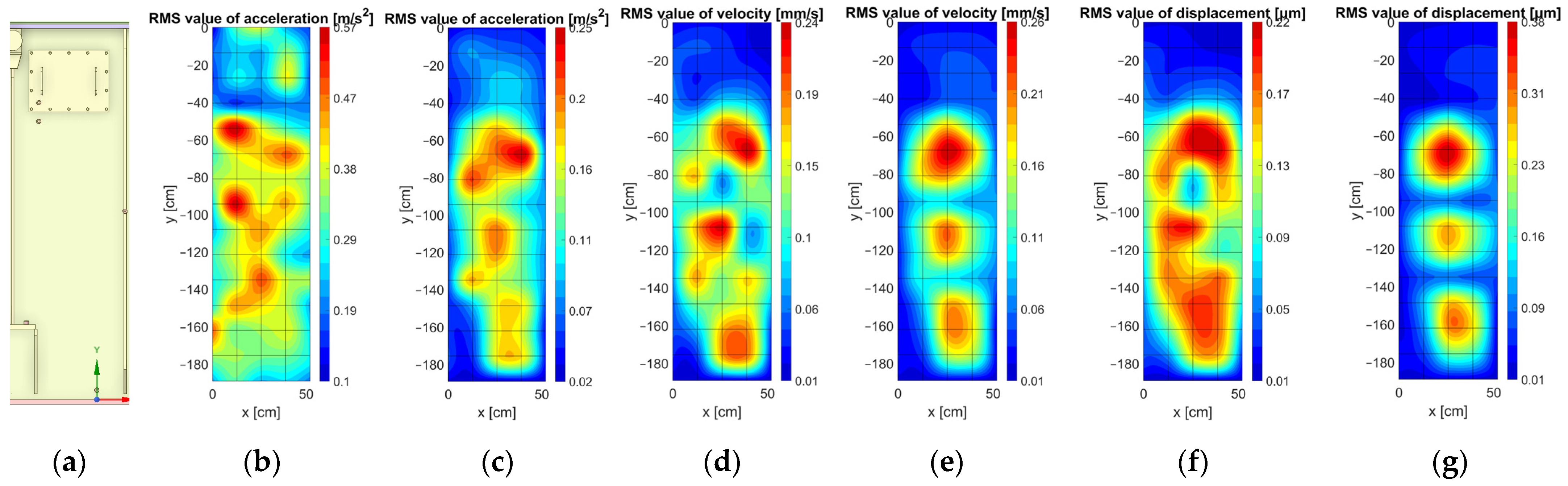
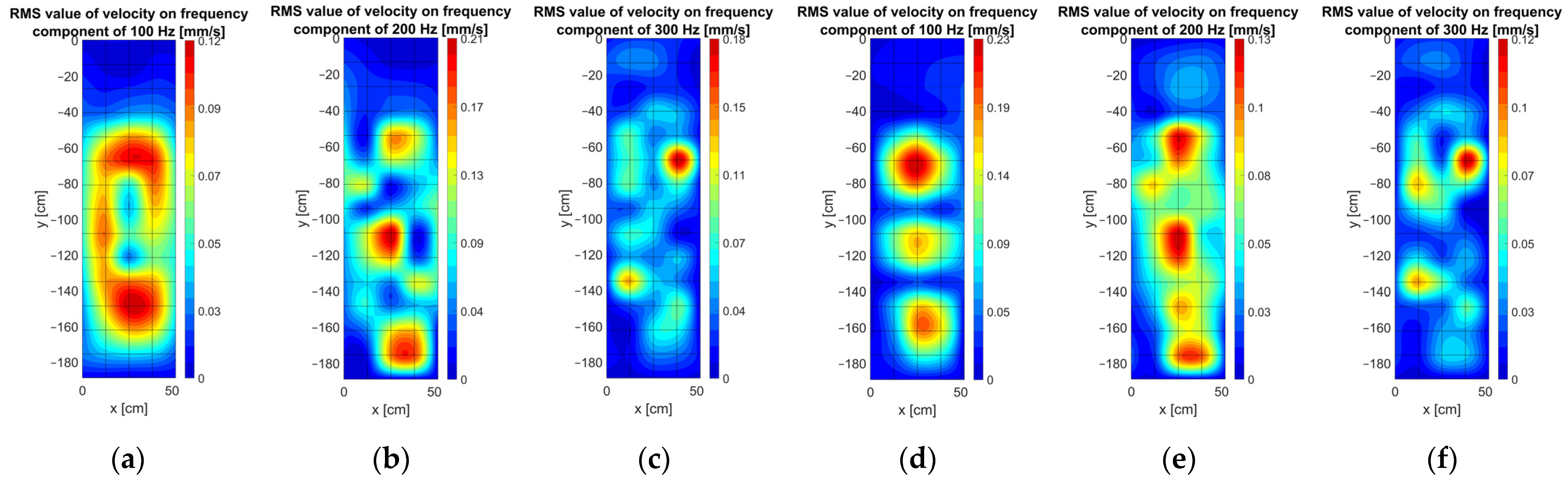
4.2. Visualization of the Measurement Results Using Matlab Interpolation Functions

The measurement results are visualized using Matlab interpolation function interp2 with alternative Modified Akima interpolation [29,30]. This nonlinear method is based on a piecewise function of polynomials of at most third order by which the values in query points are determined. The fitting curve passes through all the given data points with a smooth and natural-looking appearance. The modification is made to this algorithm so that when two flat regions meet, more weight is given to the side with a slope closer to zero to avoid overshoot. A query points are the points where a user wants to know the value. A user can define how many query points in the x and y direction wants [31]. Linear interpolation is a default in this function, but with the previously mentioned interpolation, a smoother distribution is obtained.
Figure 7 shows that the vibration distribution of RMS values is different using two different voltage sources. The grid that passes through original sampling (measurement) points is also shown. The most significant difference is visible in acceleration distribution and values. Vibration velocity and displacement are more comparable using two sources because they are obtained by acceleration integration, causing higher frequency components loss. Despite that, velocity and displacement distributions differ because low-frequency components are excited differently, as shown in Figure 6.
Figure 8 shows that regardless of similar values of vibration velocities in Figure 7, vibration distribution and values at different frequency components differ significantly using two different voltage sources. Vibration measurement results using two different voltage sources show that higher harmonics at 3 kHz, 6 kHz, and 9 kHz in source voltage significantly affect the vibration characteristics of the transformer tank wall. Vibration velocity is the most important indicator because radiated sound power of the plate is proportional to the surface mean square velocity, as is shown in (13).

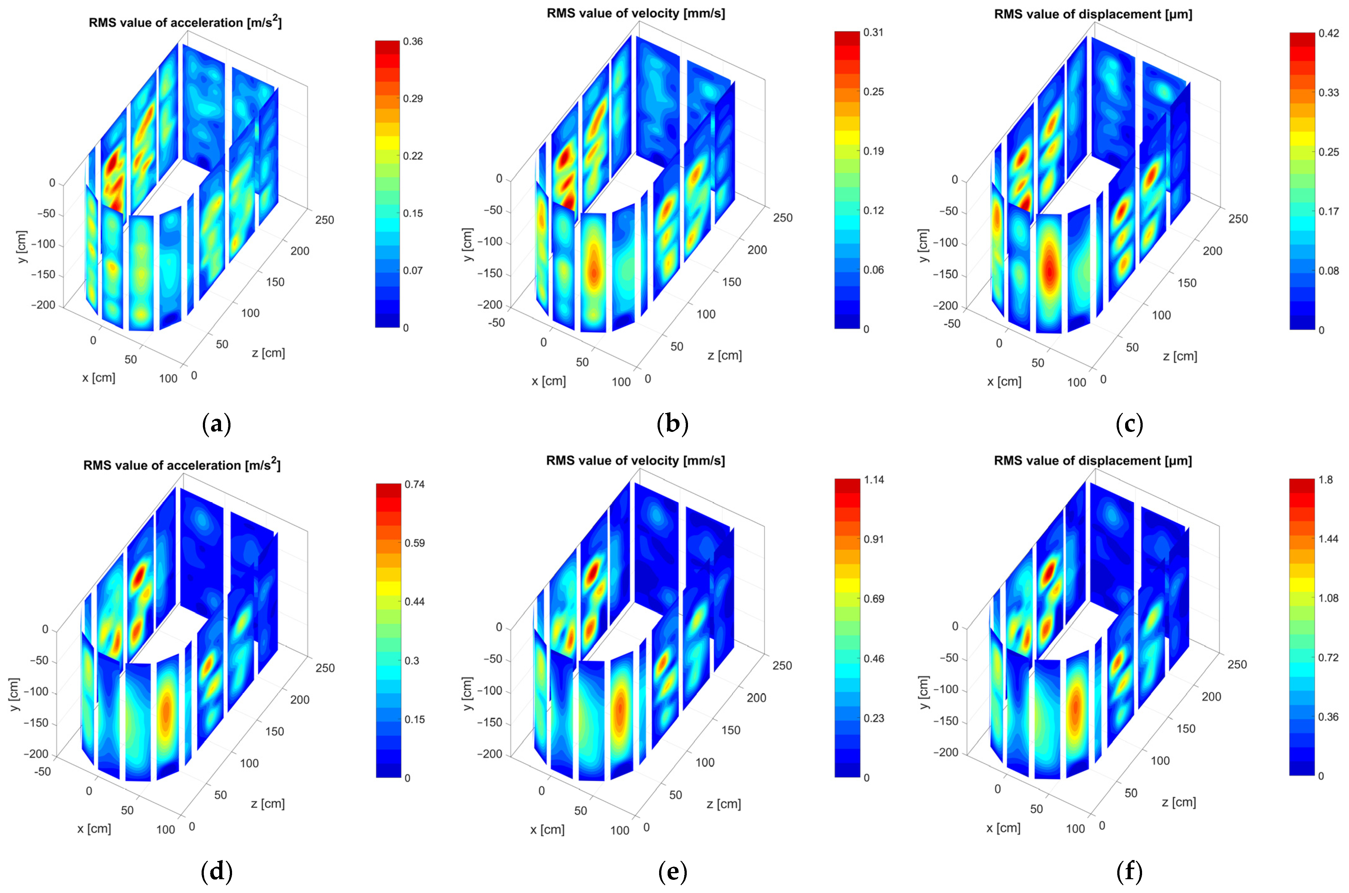
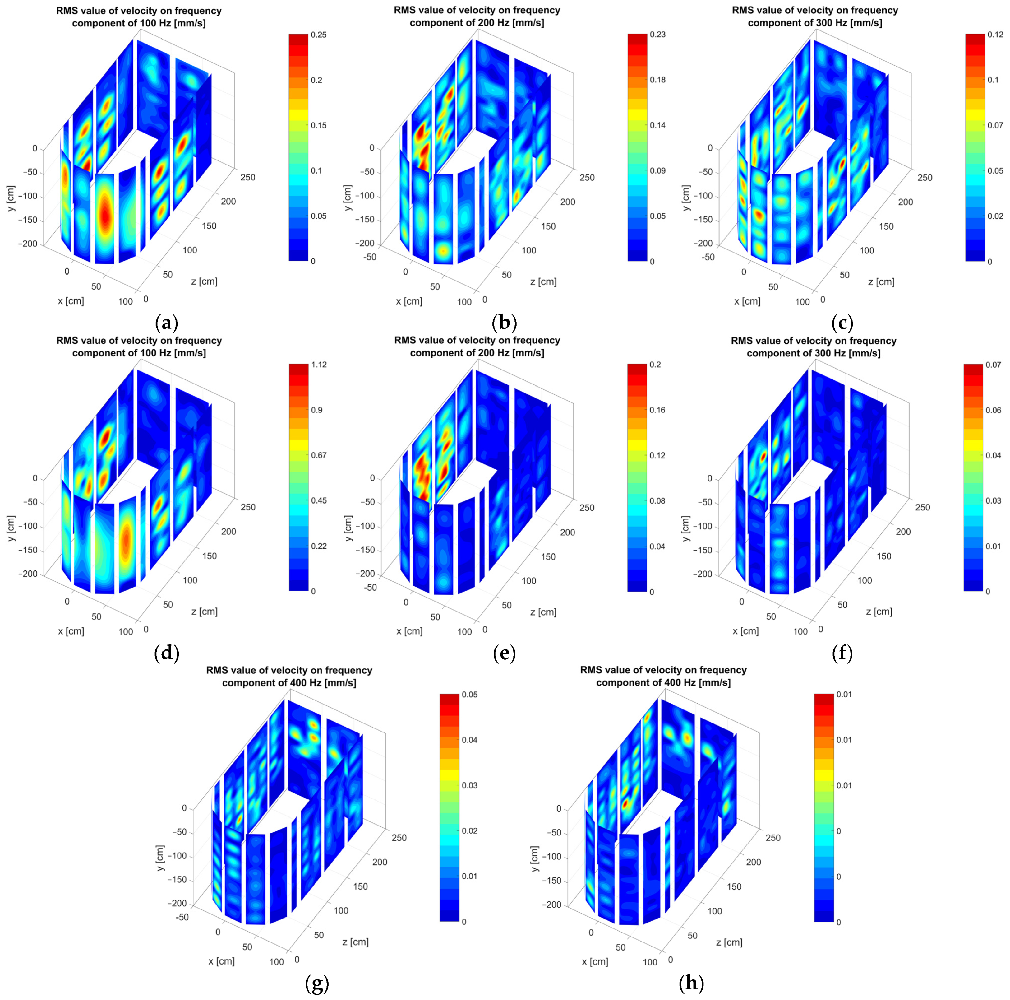
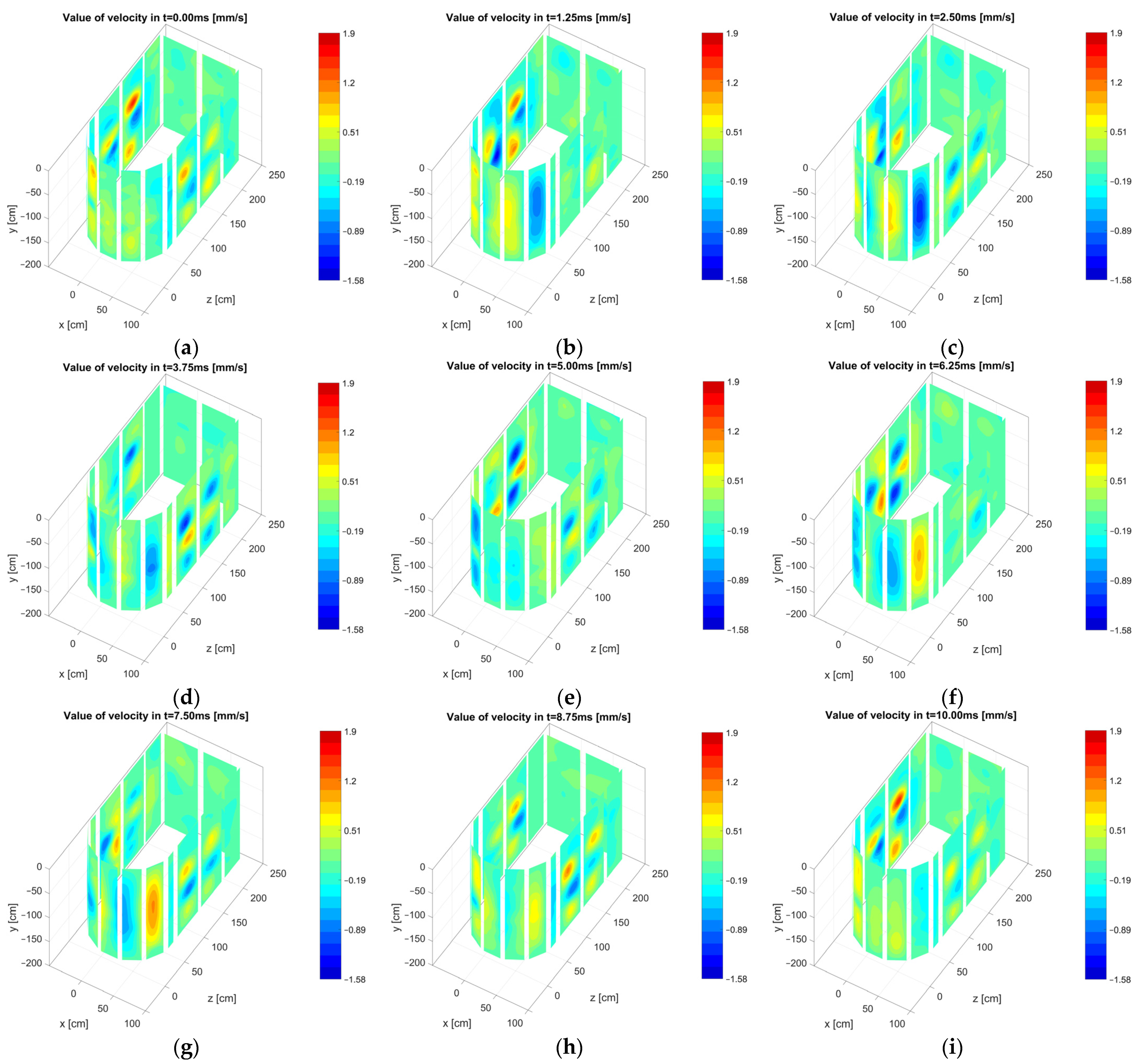
4.3. Visualization of the Tank Vibrations in 3D Space

Vibration velocity distributions of all 15 surfaces are mapped to the locations of the surfaces to visualize tank vibrations in 3D space. Depending on the surface width, surfaces have a different number of measurement points. This view shows vibrational mode shapes on the tank wall surfaces excited by vibrations of the windings in the short-circuit test or vibrations of the core in the open-circuit test.
Figure 9 shows that vibrations in the short-circuit test are higher, and different tank wall vibration modes are excited in the two tests. Maximum RMS values of acceleration, velocity and displacement in the open-circuit test are 0.36 m/s2, 0.31 mm/s, and 0.42 µm, respectively. Maximum values in short-circuit test are 0.74 m/s2, 1.14 mm/s, and 1.8 µm.
Figure 10 shows visualized RMS values of the vibration velocity of tank wall on frequency components of 100 Hz, 200 Hz, 300 Hz, and 400 Hz in open-circuit and short-circuit tests. In short-circuit test, the frequency component of 100 Hz is dominant. In open-circuit test, the first few 100 Hz harmonics are significant (100 Hz, 200 Hz, and 300 Hz). In open-circuit test highest values of vibration velocity are at surface 12 (100 Hz: 0.25 mm/s; 200 Hz: 0.23 mm/s; 300 Hz: 0.09 mm/s; 400 Hz: 0.04 mm/s), and in short-circuit test highest values are at surface 11 (100 Hz: 1.12 mm/s; 200 Hz: 0.20 mm/s; 300 Hz: 0.05 mm/s; 400 Hz: 0.01 mm/s). Similarities in the excited mode shapes on shown frequency components between two transformer tests can be observed. The most noticeable difference is that vibration velocity on the high voltage side of the transformer (surfaces 1–8) is relatively smaller in the short circuit test.
Figure 11 shows instantaneous amplitudes of vibration velocity at different time moments to understand and visualize phase shifts on every transformer surface and between them. Chosen time moments correspond to every 1/8 of a period of 100 Hz, which is dominant in the short-circuit test. The vibration that can be seen is a combination of mode shapes excited at different frequencies, although it is almost only a 100 Hz component in short-circuit test. The phase shifts between different parts of the tank are also visible. Some plots (e.g., a and e, b and f, et cetera) represent the moments in time with phases shifted by 180°. Parts with red and yellow colors in one plot have dark blue and light blue colors in the other plot and vice versa. Total vibration animations at the open-circuit test and animations of different frequency components of vibrations can be visualized using the same procedure.
It is shown in (13) that radiated sound power of the plate depends on space and time-averaged mean square surface velocity multiplied with the surface area, the specific acoustic impedance of the medium (ρ·c), and radiation efficiency of the steel plate. Radiation efficiency depends on the frequency and dimensions of the plate and significantly affects radiated sound power, but it is not in the scope of this work. The first two equation variables describe how much the vibration of the plate of a particular surface contributes to the sound power. In Figure 12 comparison of mean square surface velocity multiplied with the surface area on 15 measured surfaces for overall vibrations and vibrations at the first four harmonics of vibrations is shown. It can be observed that in the open-circuit test, surface 12 contributes the most, and in short-circuit test, it is surface 11. In both tests and at all vibration harmonics, a contribution from those two surfaces is significant.

4.4. Analytical Calculation of Critical, Crossover, and Resonant Frequencies of the Plate

Using Equations (4), (5) and (11), critical, crossover, and resonant frequencies of the transformer tank wall steel plates are calculated. Plates (surfaces) of the transformer tank wall do not have the same dimensions, and resonant frequencies of plates that are dimension-dependent differ. Critical and crossover frequency depend only on the thickness of the plate and the material properties that are the same for all the plates. In the above-mentioned equations speed of sound is c = 343 m/s2, steel density ρ = 7.8 × 10³ kg/m3, Young modulus of steel E = 210 N/m2, Poisson ratio µ = 0.33, and plate thickness h = 8 × 10⁻³ m.
The critical frequency of the steel plate thickness of 8 mm is fc = 1475 Hz, and the crossover frequency is fs = 126.9 kHz. Resonant frequencies are calculated for every plate and put in Table 2. This calculation takes a few simplifications presenting the transformer plates as perfectly flat and simply supported. Tank plates consist of access-openings, connections for coolers, variations in stiffeners shape, etc. The conditions of a simply supported rectangular plate, which say that the displacement and the moment reaction at the boundaries are zero, are not satisfied for all the plates. Boundaries of plates 1, 2, 3, 14, and 15 are not that simple because there are no stiffeners, and they have angled positions with the neighboring plates.
Comparing Table 2 with Figure 9 and Figure 10 for the plates with the highest vibration levels (5, 6, 11, and 12) where boundary conditions are satisfactorily fulfilled, it can be observed that the mode (1, 3) at the resonant frequency of 104 Hz might have an impact on the vibrations at 100 Hz. Mode (1, 3) can be seen in Figure 10 at 100 Hz component, and mode (1, 5) at 200 Hz component. From Table 2, mode (1, 5) is calculated at 185 Hz. Using this comparison of modal shapes and vibration patterns for different transformer tank plates at different frequencies, it can be concluded that using this fast method, approximative resonances can be calculated at the design stage, and at least 100 Hz component resonance can be avoided.

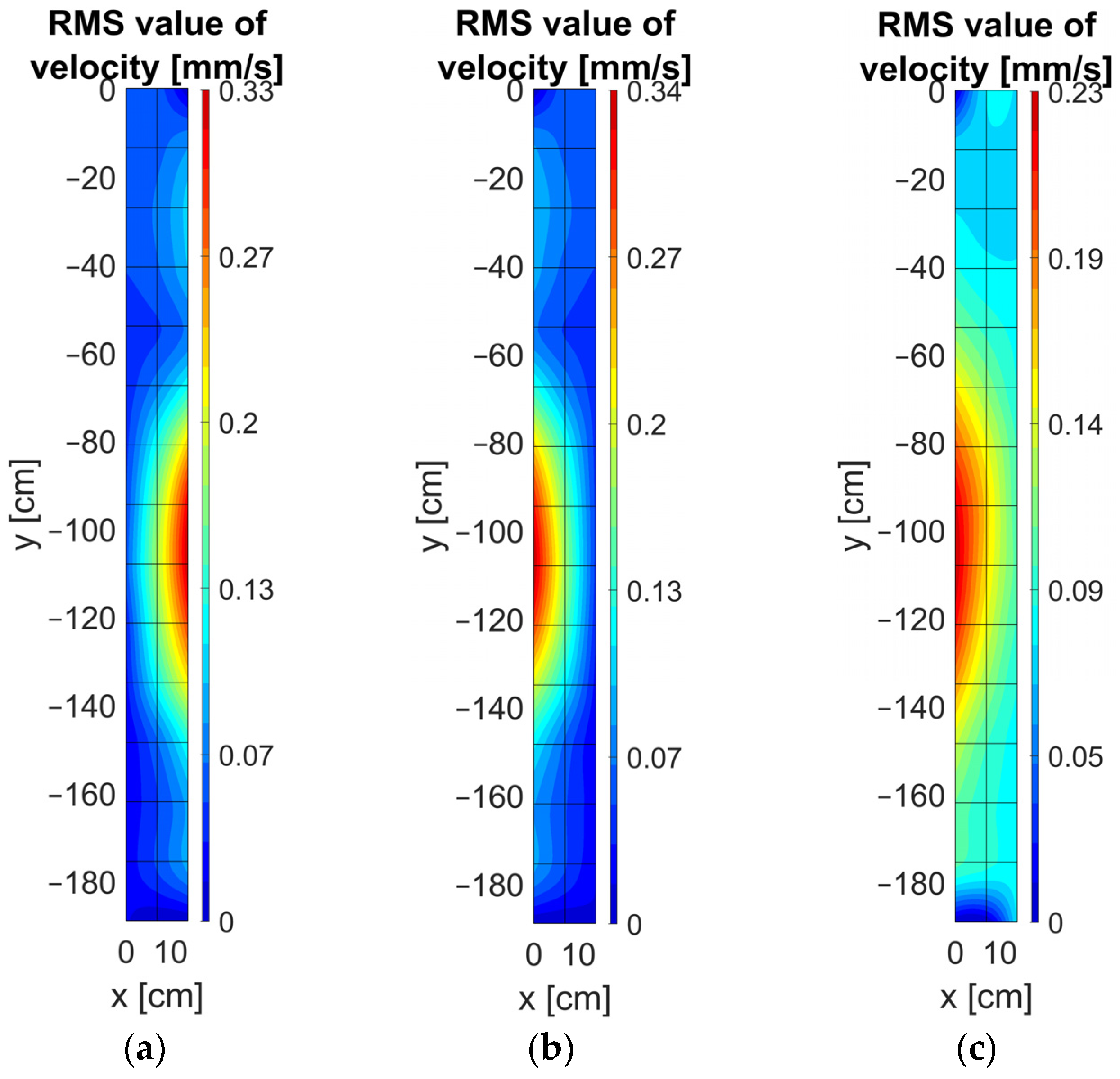
4.5. Vibrations of Tank Stiffeners and Cover

Except for the vibration measurements on the transformer tank wall plates, measurements are also carried out on the transformer stiffeners and cover in the open-circuit and short-circuit tests.
Figure 13 shows the stiffener on which vibrations are measured. Figure 14 shows that vibrations are concentrated in the middle of the free end of the stiffener 2 in both tests. Figures are plotted from the observer’s perspective from the cooler or conservator side. The vibrations of the stiffener 2 are lower in the open-circuit test. It is evident from Table 3 that vibrations of the front side in the short-circuit test are the same as the vibrations from the side surfaces of the stiffener, while in the open-circuit test those values are smaller.
The RMS values of the vibration velocity of the measurement points on the transformer tank cover from Figure 15 are shown in Table 4. The label r represents a row, and c represents a column. The vibration velocity in row 3, which is on the high voltage side, has higher values than row 2 on the low voltage side for both short-circuit and open-circuit tests. The possible cause is the proximity of the stiffener to row 2. However, the maximum vibration velocities levels at the transformer tank cover and stiffeners are about three times lower in the open-circuit test and about four times lower in the short-circuit test than on the tank wall surfaces.

5. Discussion

The RMS values of the vibration acceleration, velocity, and displacement on the tank wall surfaces are visualized in detail. The vibration velocities for different frequency components (100 Hz, 200 Hz, 300 Hz, and 400 Hz) are also shown, and open-circuit and short-circuit operating conditions are compared. In open-circuit test, the highest values of vibration velocity are at surface 12 (100 Hz: 0.25 mm/s; 200 Hz: 0.23 mm/s; 300 Hz: 0.09 mm/s; 400 Hz: 0.04 mm/s), and in short-circuit test they appear at surface 11 (100 Hz: 1.12 mm/s; 200 Hz: 0.20 mm/s; 300 Hz: 0.05 mm/s; 400 Hz: 0.01 mm/s). The alignment of vibration measurements using the voltage signal is used in order to visualize instantaneous amplitudes of vibrations using only three accelerometers. This enabled the measurements of vibrations at the same operating conditions at different moments in time and different positions using the same equipment.
Stiffener and tank cover vibrations are also measured and analyzed, and the results show significantly lower values than side surfaces (about three times lower in open-circuit test and about four times lower in short-circuit test). Calculations show that critical and crossover frequencies for the steel plate of thickness 8 mm are too high to be relevant. A fast method for the calculation of approximative resonances is given and can be used during the design stage to avoid the resonance phenomenon. The most important achievement of this work is the possibility of vibration visualization and localization of the maximum vibration spots at the entire transformer tank surface in spatial coordinates, including stiffeners and cover. This approach provides the robustness and adaptability of the method for different transformer tank geometries.
Analysis of space and time-averaged mean square surface velocity shows that radiated sound power is highest in both tests near surfaces 11 and 12. Knowing the vibration distribution at all surfaces makes it possible to estimate sound pressure levels from transformers at dominant frequency components and overall value in specific points around the tank, as presented in Section 2 of this paper. This can be used to estimate the sound power by knowing the vibration levels on the transformer surface.

6. Conclusions

In this paper, vibration measurement on a three-phase 5 MVA transformer experimental model is carried out. The main scope of this work is the comparison of vibrations using two different voltage sources and visualizing these vibrations on the transformer tank. The results can be summarized as follows.
Comparison of vibration using two different voltage sources (power converter and regulating transformer) showed that higher voltage harmonics of power converter caused high vibration components of 3 kHz and 6 kHz. In addition, the vibration distribution and RMS values are different comparing overall vibrations and different frequency components of vibrations. In general, source selection and higher harmonics in source voltage significantly affect the vibration characteristics of the transformer tank wall. The visualization of the measurements using interpolation functions is carried out, and differences are analyzed for the two different operating conditions for overall vibrations and vibrations at different frequency components. Moreover, instantaneous amplitudes of vibrations are shown. In open-circuit and short-circuit tests, a contribution from surfaces 11 and 12 is the most significant. Using the fast analytical method for modal shapes and resonance frequencies calculation, the resonance phenomenon can be avoided early in the design stage if a rectangular plate geometry and boundary conditions are satisfied. Additionally, stiffener and tank cover vibrations are also measured and analyzed.
The future work will focus on the application of the findings of this paper through different experiments that affect the transformer vibration response (which include reduction measures such as the sound panels inside the transformer tank and vibration isolators), verification of FEM analysis by studying different transmission paths for vibration excitation (through oil and mechanical connections), analytical sound pressure level calculation from known vibration distribution on surfaces, and even comparison of vibration patterns with acoustic maps given by specially design acoustic camera with an appropriate distance between the microphones and the length of the array for noise source localizations near the transformer tank.

Author Contributions

Conceptualization, T.Ž. and A.P.; methodology, K.P., T.Ž. and A.P.; software, K.P.; validation, A.P. and T.Ž.; resources, T.Ž. and A.P.; writing—original draft preparation, K.P.; writing—review and editing, A.P. and T.Ž.; visualization, K.P.; supervision, A.P. and T.Ž. All authors have read and agreed to the published version of the manuscript.

Funding

This research received no external funding.

Institutional Review Board Statement

Not applicable.

Informed Consent Statement

Not applicable.

Acknowledgments

Special thanks to Končar—Power Transformers Ltd., a Joint Venture of Siemens Energy and Končar for providing the transformer experimental model for the purpose of this measurement.

Conflicts of Interest

The authors declare no conflict of interest.

References

  1. Kulkarni, S.V.; Khaparde, S.A. Transformer Engineering: Design, Technology, and Diagnostics; CRC Press: Boca Raton, FL, USA; Taylor & Francis Group: Oxfordshire, UK, 2013; ISBN 9781439854181. [Google Scholar]
  2. Jin, M.; Pan, J. Vibration Transmission from Internal Structures to the Tank of an Oil-Filled Power Transformer. Acoustics 2016, 113, 1–6. [Google Scholar] [CrossRef]
  3. IEC 60076-10; Power Transformers—Part 10: Determination of Sound Levels. International Electrotechnical Commission: Geneva, Switzerland, 2016.
  4. IEC 60076-10-1; Power Transformers—Part 10-1: Determination of Sound Levels—Application Guide. International Electrotechnical Commission: Geneva, Switzerland, 2016.
  5. Beltle, M.; Tenbohlen, S. Usability of Vibration Measurement for Power Transformer Diagnosis and Monitoring. In Proceedings of the 2012 IEEE International Conference on Condition Monitoring and Diagnosis, CMD 2012, Bali, Indonesia, 23–27 September 2012; pp. 281–284. [Google Scholar] [CrossRef]
  6. Jin, M.; Pan, J.; Huang, H.; Zhou, J. Transmission of Vibration of a Power Transformer from the Internal Structures to the Tank. In Proceedings of the Acoustics Fremantle 2012, Fremantle, Australia, 21–23 November 2012. [Google Scholar]
  7. Zhang, F.; Ji, S.; Shi, Y.; Zhan, C.; Zhu, L. Investigation on Vibration Source and Transmission Characteristics in Power Transformers. Appl. Acoust. 2019, 151, 99–112. [Google Scholar] [CrossRef]
  8. Hackl, A.; Hamberger, P. Investigation of Surface Velocity Pattern of Power Transformers Tanks. In Proceedings of the 19th International Conference on Electrical Machines, ICEM 2010, Rome, Italy, 6–8 September 2010. [Google Scholar] [CrossRef]
  9. Hrkac, M.; Kmita, G.; Kozupa, M.; Platek, R.; Sekula, R.; Zannol, R. Vibroacoustic Behavior of a Small Power Transformer. In Proceedings of the International Colloquium Transformer Research and Asset Management, Dubrovnik, Croatia, 16–18 May 2012; pp. 1–8. [Google Scholar]
  10. Lu, Z.; Zhang, C.; Wang, T.; Yu, H.; Wang, Z.; Li, C.; Liu, G. Measurement and Analysis of UHV Transformer Noise with Sound Intensity and Vibration Method. In Proceedings of the 2017 20th International Conference on Electrical Machines and Systems, ICEMS 2017, Sydney, Australia, 11–14 August 2017. [Google Scholar] [CrossRef]
  11. Wu, X.; Zhou, N.; Shi, Y.; Ji, S.; Fan, Z.; Lu, W.; Hu, S. Vibration Distribution Characteristics on Oil-Tank Surface of a Single-Phase Transformer. In Proceedings of the ICEMPE 2017—1st International Conference on Electrical Materials and Power Equipment, Xi’an, China, 14–17 May 2017; pp. 344–348. [Google Scholar] [CrossRef]
  12. Zhang, F.; Ji, S.; Shi, Y.; Zhu, L. Investigation on the Action of Eddy Current on Tank Vibration Characteristics in Dry-Type Transformer. IEEE Trans. Magn. 2019, 55, 8400908. [Google Scholar] [CrossRef]
  13. Shi, Y.; Ji, S.; Zhang, F.; Dang, Y.; Zhu, L. Application of Operating Deflection Shapes to the Vibration-Based Mechanical Condition Monitoring of Power Transformer Windings. IEEE Trans. Power Deliv. 2021, 36, 2164–2173. [Google Scholar] [CrossRef]
  14. Hu, Y.; Zheng, J.; Huang, H. Experimental Research on Power Transformer Vibration Distribution under Different Winding Defect Conditions. Electronics 2019, 8, 842. [Google Scholar] [CrossRef] [Green Version]
  15. Yang, F.; Ren, Z.; Zhang, D.; Li, L.; Fan, X.; Zhou, Y. Simulation Analysis and Experiment Validation of Vibration and Noise of Oil-Immersed Transformer. In Proceedings of the 2019 22nd International Conference on Electrical Machines and Systems, ICEMS 2019, Harbin, China, 11–14 August 2019; pp. 1–5. [Google Scholar] [CrossRef]
  16. Wang, Y.; Pan, J.; Jin, M. Finite Element Modelling of the Vibration of a Power Transformer. In Proceedings of the ACOUSTICS 2011, Gold Coast, Australia, 2–4 November 2011; Volume 34. [Google Scholar]
  17. Case, J. Numerical Analysis of the Vibration and Acoustic Characteristics of Large Power Transformers. Doctoral Dissertation, Queensland University of Technology, Brisbane, Australia, 2017. [Google Scholar]
  18. Yoshida, K.; Hoshino, T.; Murase, S.; Murakami, H.; Miyashita, T. Analysis of Load Noise Components in Small Core-Form Transformers. IEEE Trans. Power Deliv. 2021, 36, 2694–2704. [Google Scholar] [CrossRef]
  19. Hsu, C.H.; Lee, S.L.; Lin, C.C.; Liu, C.S.; Chang, S.Y.; Hsieh, M.F.; Huang, Y.M.; Fu, C.M. Reduction of Vibration and Sound-Level for a Single-Phase Power Transformer with Large Capacity. IEEE Trans. Magn. 2015, 51, 84032040. [Google Scholar] [CrossRef]
  20. Bouayed, K.; Mebarek, L.; Lanfranchi, V.; Chazot, J.D.; Marechal, R.; Hamdi, M.A. Noise and Vibration of a Power Transformer under an Electrical Excitation. Appl. Acoust. 2017, 128, 64–70. [Google Scholar] [CrossRef]
  21. Zhang, B.; Yan, N.; Du, J.; Han, F.; Wang, H. A Novel Approach to Investigate the Core Vibration in Power Transformers. IEEE Trans. Magn. 2018, 54, 8400804. [Google Scholar] [CrossRef]
  22. Holger Rindel, J. Sound Insulation in Buildings; CRC Press: Boca Raton, FL, USA, 2017; ISBN 9781498700429. [Google Scholar]
  23. Meyer, E.; Neumann, E.-G. Physical and Applied Acoustics: An Introduction; Academic Press: Cambridge, MA, USA, 1972; ISBN 978-0124931503. [Google Scholar]
  24. Takatsubo, J.; Ohno, S.; Suzuki, T. Calculation of the Sound Pressure Produced by Structural Vibration Using the Results of Vibration Analysis. Bull. JSME 1983, 26, 1970–1976. [Google Scholar] [CrossRef] [Green Version]
  25. Bies, D.A.; Hansen, C.H. Engineering Noise Control: Theory and Practice, 4th ed.; Spon Press: London, UK, 2009; ISBN 9781482288704. [Google Scholar]
  26. Maidanik, G. Response of Ribbed Panels to Reverberant Acoustic Fields. J. Acoust. Soc. Am. 1962, 34, 809–826. [Google Scholar] [CrossRef] [Green Version]
  27. Wang, Y.; Jin, H.; Cai, X.; Gong, P.; Jiang, X. Study on the Sound Radiation Efficiency of a Typical Distribution Transformer. IEEE Access 2021, 9, 125151–125157. [Google Scholar] [CrossRef]
  28. Hohenwarter, D. Noise Radiation of (Rectangular) Plane Sources. Appl. Acoust. 1991, 33, 45–62. [Google Scholar] [CrossRef]
  29. Akima, H. A New Method of Interpolation and Smooth Curve Fitting Based on Local Procedures. J. ACM (JACM) 1970, 17, 589–602. [Google Scholar] [CrossRef]
  30. Akima, H. A Method of Bivariate Interpolation and Smooth Surface Fitting Based on Local Procedures. Commun. ACM 1974, 17, 18–20. [Google Scholar] [CrossRef]
  31. Interpolation for 2-D Gridded Data in Meshgrid Format—MATLAB Interp2. Available online: https://www.mathworks.com/help/matlab/ref/interp2.html (accessed on 8 June 2021).
Figure 1. Electrical and vibration measurement setup diagram in open-circuit and short-circuit tests.
Energies 15 00492 g001
Figure 2. (a) Vibration measurement on the 5 MVA transformer experimental model with measurement points marked with red crosses (on a couple of surfaces crosses highlighted with photo editor) and three accelerometers in the short-circuit test, (b) Top view of the CAD model with numbers presenting transformer surfaces on which measurements are made.
Energies 15 00492 g002
Figure 3. Single-sided amplitude spectrum of Signal to Noise Ratio for point 75 at the surface 5 of the transformer.
Energies 15 00492 g003
Figure 4. Voltage and acceleration signals of the reference point and some different points on the tank: (a,c) before alignment and (b,d) after alignment.
Energies 15 00492 g004
Figure 5. Single-sided amplitude spectrum of voltage and voltage signal in the time domain in the open-circuit test using (a) power converter and (b) regulating transformer.
Energies 15 00492 g005
Figure 6. Single-sided amplitude spectrum of vibration acceleration, velocity, and displacement in the open-circuit test using (a) power converter and (b) regulating transformer.
Energies 15 00492 g006
Figure 7. (a) CAD model of the surface 5 of the transformer experimental model, and visualization of RMS values of the vibration acceleration, velocity, and displacement on the surface 5 using: (b,d,f) power converter as the source and (c,e,g) regulating transformer as a source.
Energies 15 00492 g007
Figure 8. Visualization of RMS values of the vibration velocity on the surface 5 of the transformer using: (ac) power converter and (df) regulating transformer as a source on different frequency components.
Energies 15 00492 g008
Figure 9. Visualization of RMS values of the vibration acceleration, velocity, and displacement in 3D space in: (ac) open-circuit test, and (df) short-circuit test.
Energies 15 00492 g009
Figure 10. Visualization of RMS values of the vibration velocity in 3D space on the frequency components of 100 Hz, 200 Hz, 300 Hz, and 400 Hz in (ac,g) open-circuit and (df,h) short-circuit test.
Energies 15 00492 g010
Figure 11. Visualization of the instantaneous amplitudes of the vibration velocity in 3D space in the time moments: (a) 0 ms, (b) 1.25 ms, (c) 2.5 ms, (d) 3.75 ms, (e) 5 ms, (f) 6.25 ms, (g) 7.5 ms, (h) 8.75 ms, and (i) 10 ms in the short-circuit test.
Energies 15 00492 g011
Figure 12. Space and time-averaged mean square vibration velocity of the plate multiplied with surface area for 15 measured transformer surfaces marked in Figure 2b.
Energies 15 00492 g012
Figure 13. Stiffener 2 of transformer experimental model on which vibrations are measured with a view to (a) the conservator side (b) the front side and the cooler side.
Energies 15 00492 g013
Figure 14. Visualization of the RMS values of the vibration velocity on the stiffener 2 from (a) the conservator side in the open-circuit test (b) the cooler side in the open-circuit test, and (c) the cooler side in the short-circuit test.
Energies 15 00492 g014
Figure 15. CAD model of the transformer experimental model in the top view with marked points of vibration measurements (red crosses) on the tank cover.
Energies 15 00492 g015
Table 1. Specifications of the accelerometer PCB Piezotronics 608A11.
Sensitivity (±15%)10.2 mV/(m/s2)
Measurement Range±490 m/s2
Frequency Range (±3 dB)0.5–10,000 Hz
Resonant Frequency22 kHz
Broadband Resolution3434 µm/s2
Temperature Range−54 °C to +121 °C
Enclosure RatingIP68
Spectral Noise (100 Hz)49.1 (µm/s2)/√Hz
Table 2. Resonant frequencies and modes of vibrations of 15 transformer plates calculated analytically.
PlateResonant Frequency [Hz] (Mode of Vibration)
1, 2, 3,
14, 15
193 (1, 1)208 (1, 2)233 (1, 3)269 (1, 4)315 (1, 5)371 (1, 6)437 (1, 7)513 (1, 8)
4, 13312 (1, 1)327 (1, 2)352 (1, 3)388 (1, 4)434 (1, 5)490 (1, 6)556 (1, 7)632 (1, 8)
5, 6,
11, 12
63 (1, 1)79 (1, 2)104 (1, 3)140 (1, 4)185 (1, 5)238 (2, 1)241 (1, 6)253 (2, 2)
279 (2, 3)307 (1, 7)314 (2, 4)360 (2, 5)384 (1, 8)416 (2, 6)470 (1, 9)482 (2, 7)
7, 10118 (1, 1)133 (1, 2)158 (1, 3)194 (1, 4)240 (1, 5)296 (1, 1)362 (1, 7)438 (1, 8)
8, 962 (1, 1)77 (1, 2)102 (1, 3)138 (1, 4)184 (1, 5)232 (2, 1)240 (1, 6)247 (2, 2)
273 (2, 3)306 (1, 7)308 (2, 4)354 (2, 5)382 (1, 8)410 (2, 6)469 (1, 9)476 (2, 7)
Table 3. RMS values of the vibration velocity along the height on the stiffener 2 from the front side in the open-circuit (OC) and short-circuit (SC) test.
y [cm]RMS Velocity (OC) [mm/s]RMS Velocity (SC) [mm/s]
00.020.06
−270.030.16
−540.040.21
−810.090.24
−1080.090.23
−1350.100.20
−1620.040.11
−1890.030.05
Table 4. RMS values of the vibration velocity on the transformer tank cover in the open-circuit (OC) and short-circuit (SC) tests.
RMS Velocity [mm/s]c1c2c3c4c5c6
OC
r10.010.020.010.020.030.02
r20.060.060.040.030.090.02
r30.060.080.090.100.060.02
r40.010.020.020.010.010.02
SC
r10.090.090.040.030.020.01
r20.080.130.130.220.200.03
r30.050.390.260.290.080.03
r40.060.020.050.040.020.02
Publisher’s Note: MDPI stays neutral with regard to jurisdictional claims in published maps and institutional affiliations.

