
Developed Transfer Function Allows Hydro Generators to Enter the Full Range of Ancillary Services Market

Abstract
:1. Introduction
2. Fundamentals and Review of Applications: The Hydro Power Plants Providing FCR
2.1. PSHP Participation in the Ancillary Services Market
2.2. BESS Participation in the Ancillary Services Market
3. The Methodology and Mathematical Models
- Using the results of real measurements of a hydro-generator (PSHP), while FCR is activated, to develop a methodology for determining the transfer function;
- Determining the transfer function suitable for use in real controllers; and
- Checking the suitability of the obtained transfer function for hydro “pit” compensation while the FCR operates.
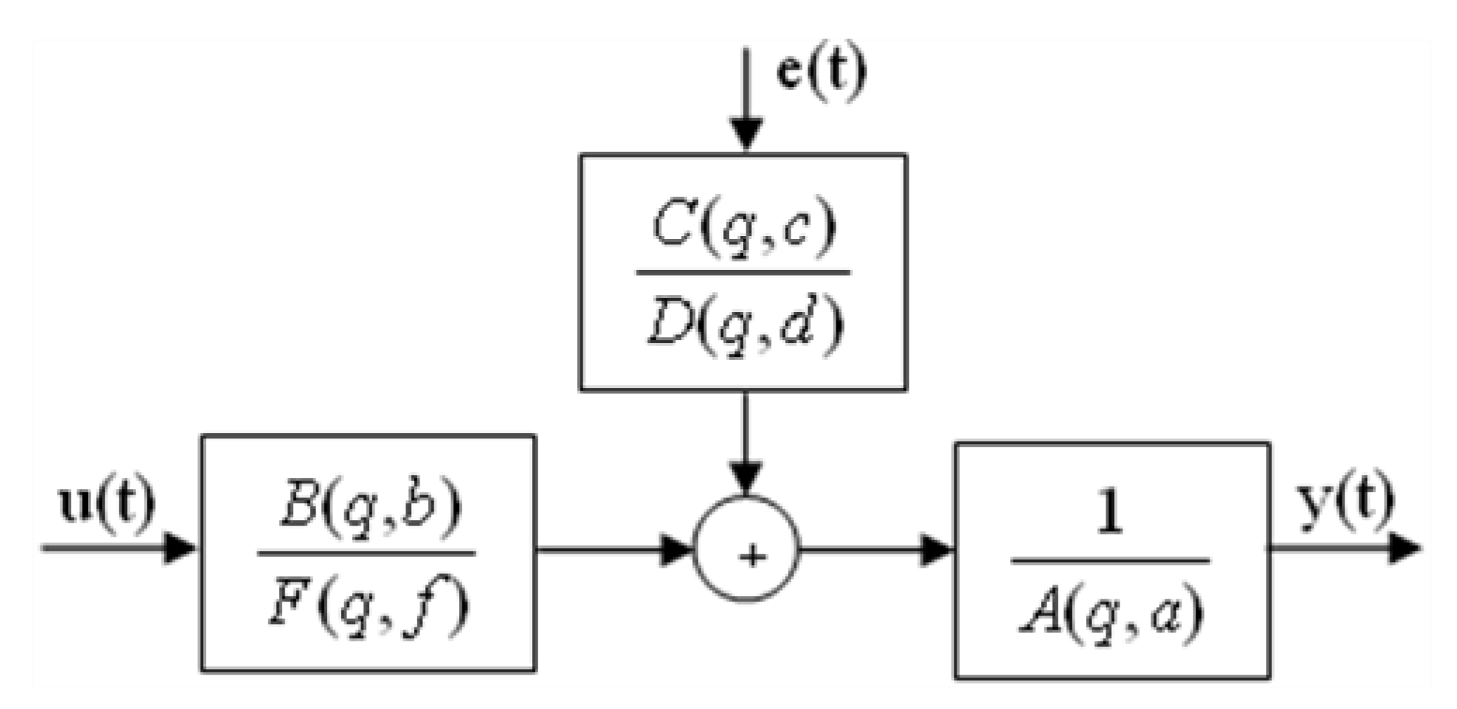
3.1. ARMAX Model
3.2. OE Model
3.3. BJ Model
3.4. The Data Used in the Calculations
3.5. The Developed and Proposed Methodology
- 1.
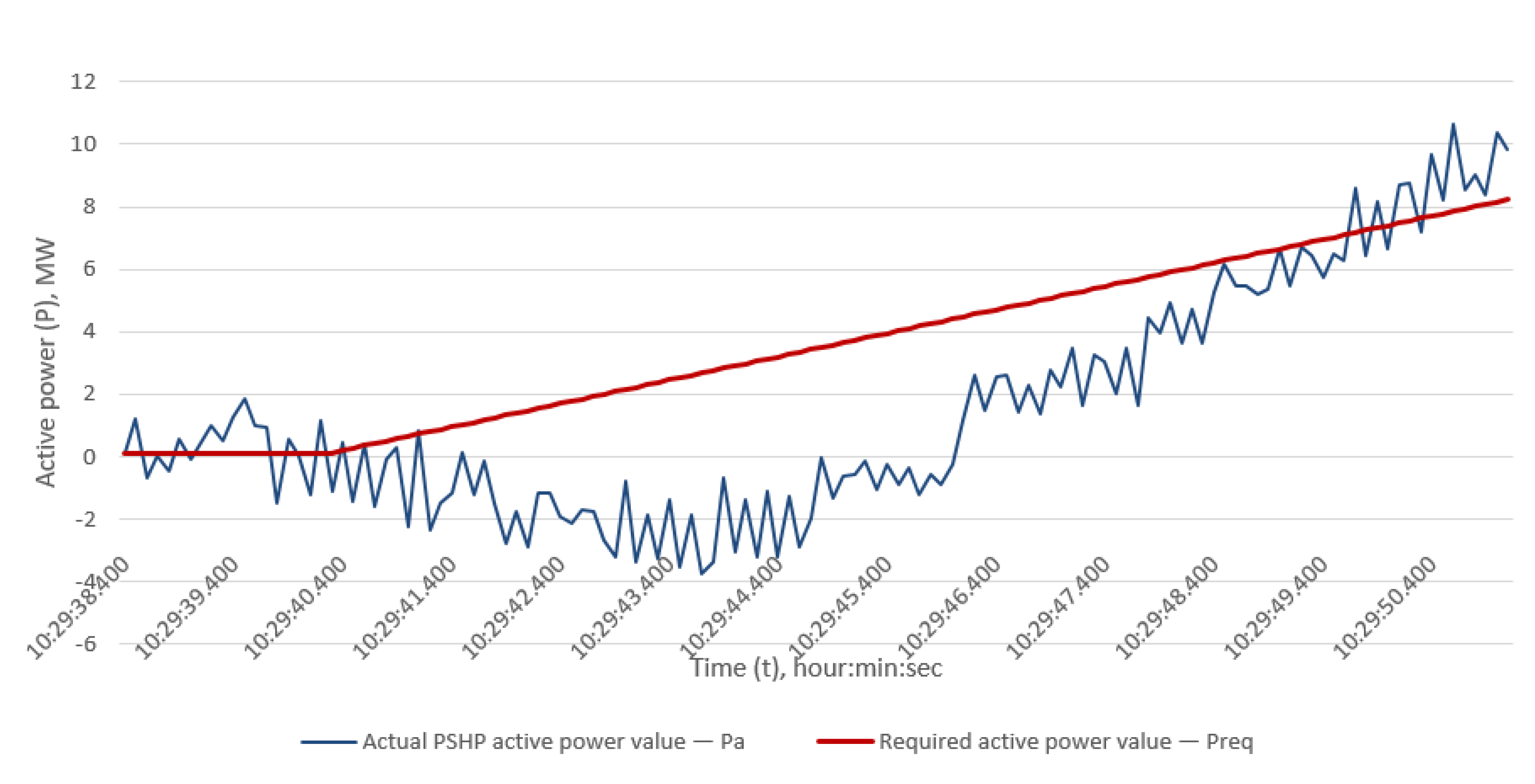
- The required active power value Preq was calculated to activate FCR, based on FCR requirements (in accordance with the requirements stated in [6]).
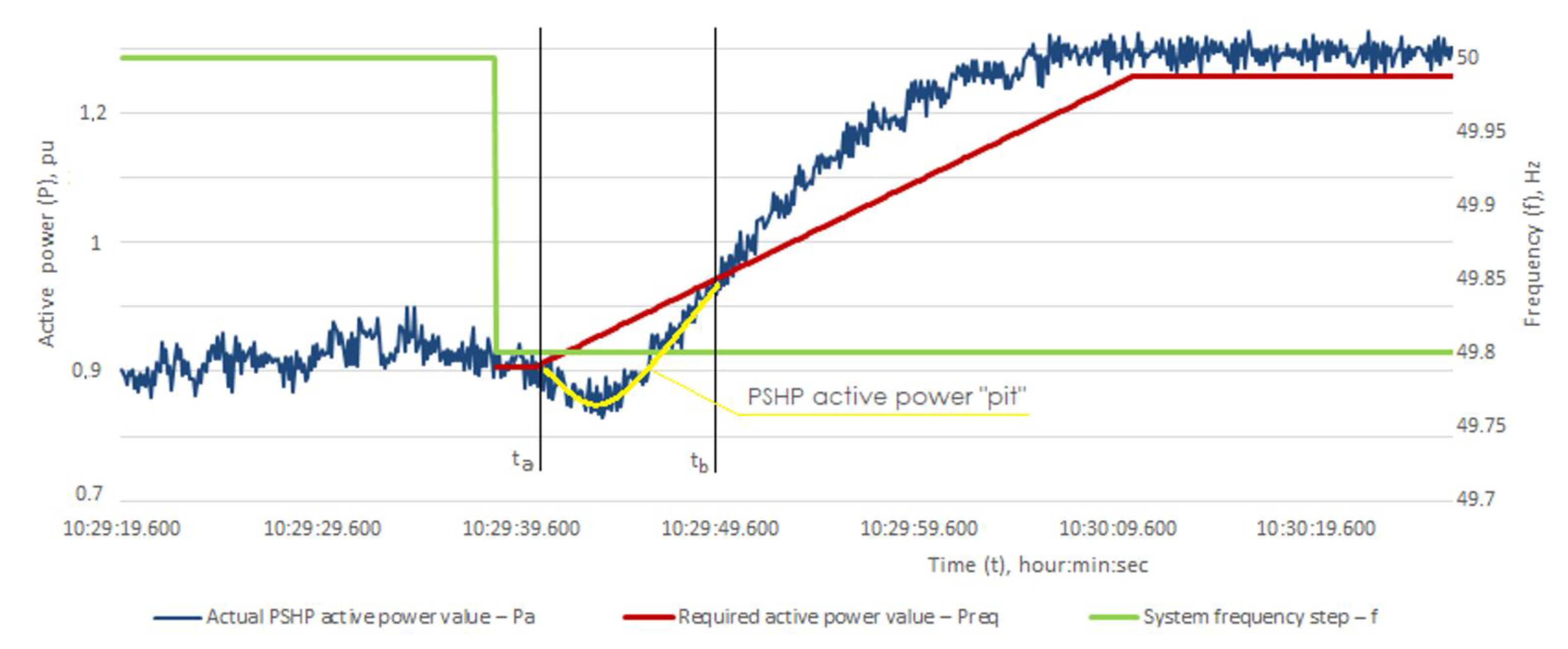
- 2.
- Active power difference PΔ was calculated, at t1 = i + tst, for each time period i, between the actual PSHP active power value Pa and the required active power Preq for FCR:For further calculations, the measurement data were used in the time interval, from ta to tb (Figure 2). The active power differences PΔ1(−200), PΔ1(+200), PΔ2(−200), and PΔ2(+200) were calculated for each curve in the range from ti to tb, Pn1(−200), Pn1(+200), Pn2(−200), Pn2(+200).
- 3.
- Measurement data were aggregated and obtained three different measurement data sets (hereinafter “Measurements”):
- 3.1
- First Measurements: maximum value PΔ1(−200), PΔ1(+200), PΔ2(−200), and PΔ2(+200) in the range (ta; tb). That means the maximum value from four real measured curves was used to compile a new curve;
- 3.2
- Second Measurements: one of four curves was selected, taking into account the maximum deviation of PΔ1(−200), PΔ1(+200), PΔ2(−200), and PΔ2(+200) curves by amplitude in the range (ti; tb).
- 3.3
- Third Measurements: the arithmetic mean of four curves was calculated:
- 4.
- New value is calculated when the aggregated curve of each Measurement is moved upward so that the active power crosses zero value at time ta when FCR is activated. Therefore, the initial value of active power at time ta is subtracted from all values of active power up to tb so that the initial value of PΔ starts from zero (Figure 4):
- 5.
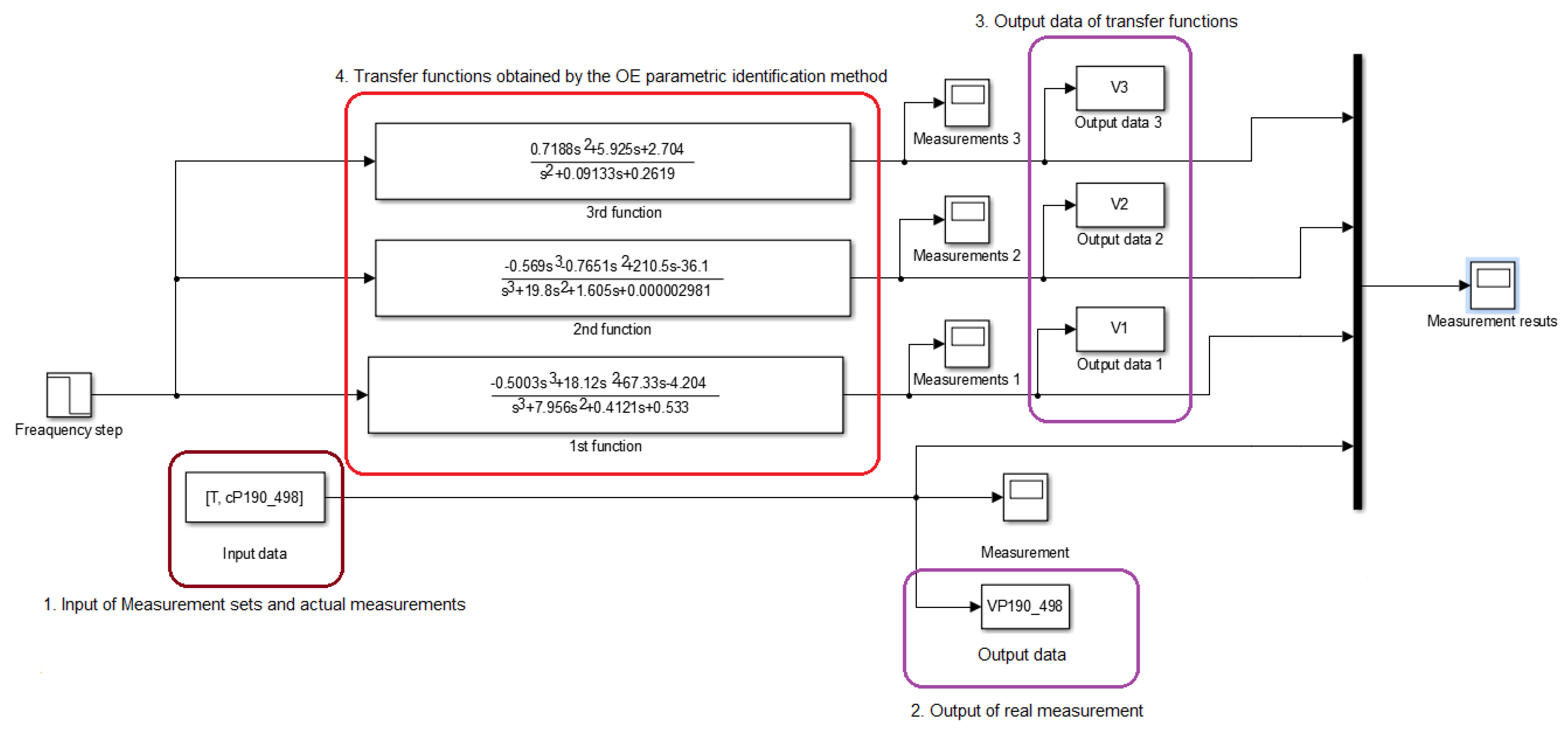
- Parametric identification was performed using the aggregated Measurements obtained in the fourth point of the methodology. Three sets of discrete transfer functions for each Measurement were obtained using the BJ, ARMAX, and OE parametric identification models. Transfer functions for the first set are presented below. The transfer function in (22) was obtained by the OE model, that of (23) was obtained by ARMAX, and that of (24) was obtained by BJ. The other two sets of transfer functions are not presented in this paper.
- 6.
- Ryŷ and R2 coefficients were calculated for all three sets of transfer functions to choose the most accurate transfer function. The calculation results are presented in Table 1.
- 7.
- The continuous transfer functions are derived from the discrete transfer function (first sets—(22)–(24); second and third sets not presented in the paper) using Laplace transform. Such a transform is performed to facilitate implementation of the controller algorithm in practice, as most controllers support continuous transfer functions, and moreover, it simplifies the tuning work of controllers, as continuous transfer functions are engineer-friendly (engineers usually have more experience with continuous transfer functions). The continuous transfer function in (25) was obtained by the OE model, that of (26) was obtained by ARMAX, and that of (27) was obtained by BJ.Other sets (second and third) of transfer functions were obtained using the same method.
- 8.
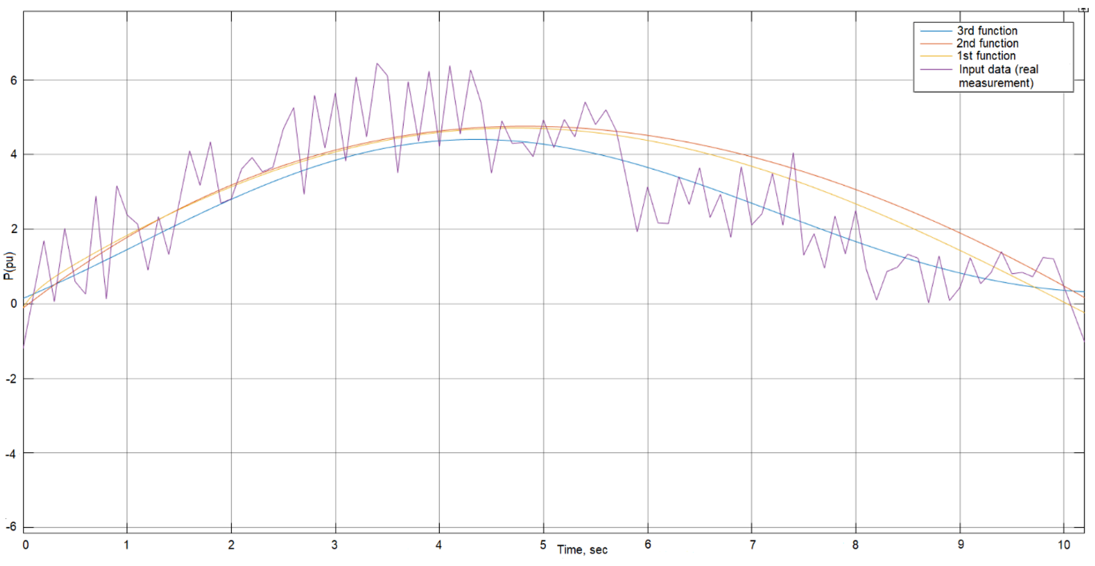
- The most accurate transfer functions that were obtained by the OE parametric identification model were selected based on the Ryŷ and R2 calculated in the sixth point of the methodology. As we see from the results presented in Table 1, the OE parametric identification model is 2.31% more accurate than ARMAX and 4.04% more accurate than BJ. The transfer functions in (28)–(30) obtained by the OE model have the highest Ryŷ (0.908). These transfer functions are used in further calculations. It is worth mentioning that (28) obtained by the OE model using first Measurements are a maximum value (3.1), that (29) obtained using the second Measurements are the maximum deviation (3.2), and that (30) obtained using the third Measurements are the arithmetic mean (3.3).
- 9.
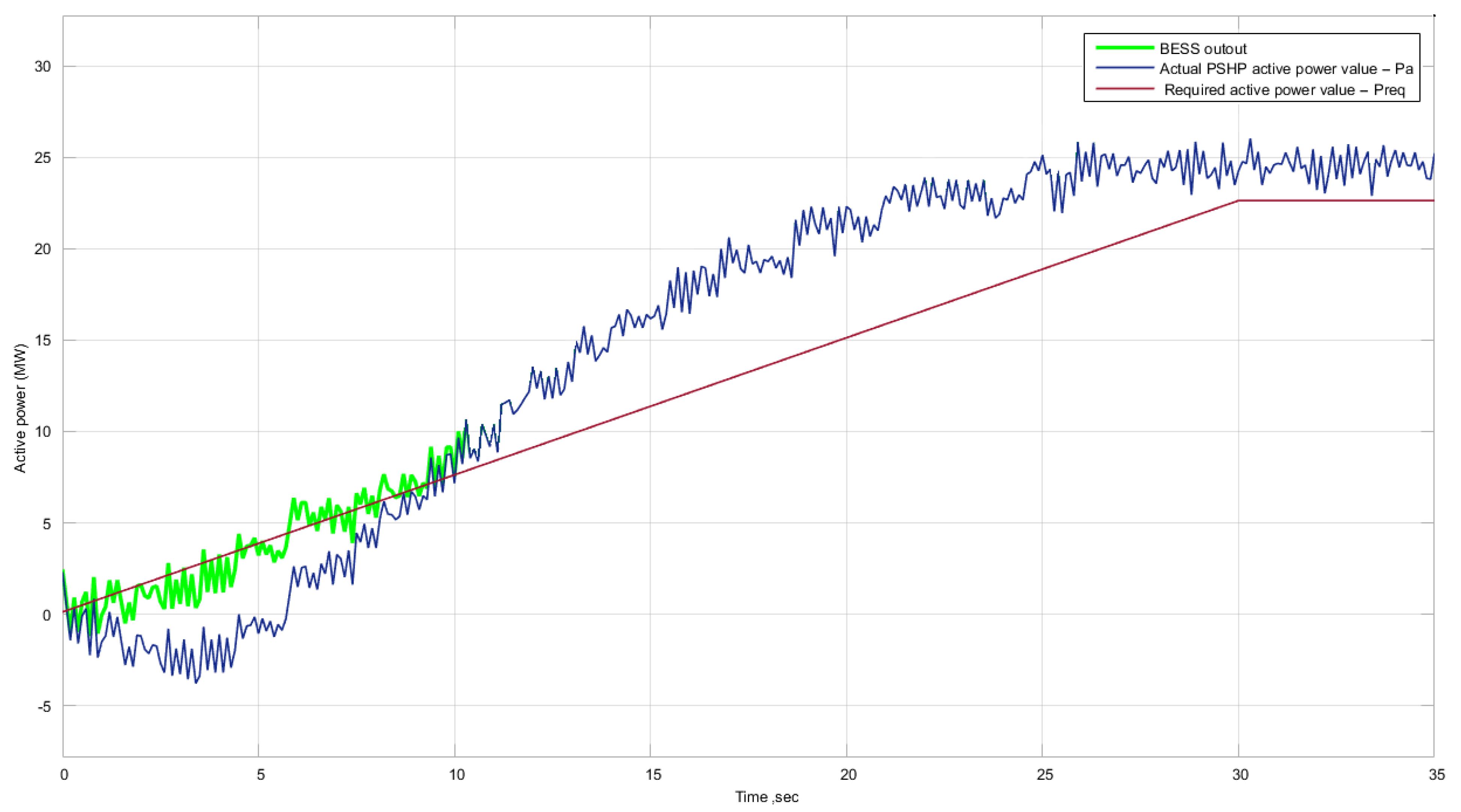
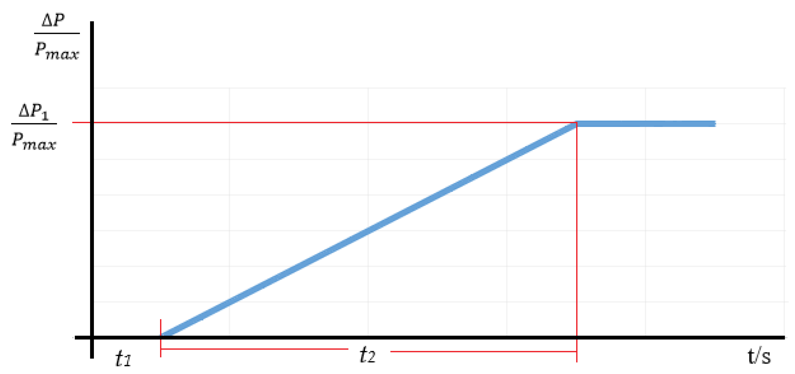
- To be able to achieve optimal performance of BESS covering active power “pit”, it is necessary to calculate proper sizing of the battery. In general, BESS capacity (MWh) is calculated by using Equation (31):Therefore, with real measurement data of the PSHP, more accurate mathematical equations are used (Equation (32)). It requires accurate measurements with a high sampling rate.The simplified Equation (33) presents how to calculate BESS capacity (MWh) in a more convenient way if real measurements of PSHP are known:The BEES power in MW can be calculated using the maximum value between Pa and Preq in time periods ta and tb of the real data measurements of PSHP presented in Figure 4:
4. Results and Discussion
5. Validation of Transfer Function Modeling BESS
6. Conclusions
Author Contributions
Funding
Institutional Review Board Statement
Informed Consent Statement
Data Availability Statement
Conflicts of Interest
Nomenclature
| the active power range and the maximum power ratio (frequency response range); | |
| t1 | the maximum allowable initial delay, up to 2 s; |
| t2 | the maximum allowed activation time, up to 30 s; |
| A, B, C, D, F | polynomial functions; |
| q | the time shift operator; |
| u(t) | freely variable input variable (e.g., control signal); |
| y(t) | output variable; |
| e(t) | sequence of unrelated random values, also called white noise; |
| a, b, c, d, f | vectors of parameters of corresponding polynomials; |
| y(t) | output at time t; |
| u(t) | input at time t; |
| na | the order of the autoregressive (AR) model; |
| nb | the order of the exogenous input model (X); |
| nc | the order of the moving average model (MA) |
| nk | number of input samples; |
| y(t−1)…y(t−na) | primary outputs; |
| u(t−nk)…u(t−nk− nb+1) | primary and delayed inputs; |
| e(t−1)…e(t−nc) | white noise value; |
| the parameter vector; | |
| na, nb, nc | coefficients of ARMAX model variables; |
| nk | a delay of ARMAX; |
| q | the backward shift operator of ARMAX; |
| correlation function; | |
| actual/measured value; | |
| y(t) | value of the parameter of ; |
| R2 | determination coefficient; |
| RMSE | root-mean-square error; |
| tst | FCR activation delay, which is determined for each HPP individually; |
| n | sampling of measurement data (measurement time step); |
| P | active power, pu; |
| f | frequency, mHz; |
| the capacity, MWh; | |
| t | time period for capacity calculation, sec; |
| P | active power, MW; |
| needed BESS capacity, MWh; | |
| required capacity, MWh; | |
| BESS actual capacity, MWh; | |
| ta, tb | time period for the calculation of needed BESS capacity (duration of PSHP active power “pit”), sec; |
| required active power according to [6], MW; | |
| the actual power output of PSHP, MW; | |
| k | battery activation time in hours, depending on characteristics of PSHP generator; |
| j | battery activation quantity providing FRC services, times per hour; |
| needed BESS power, MW; | |
| coefficient of battery depth of discharge, pu; | |
| coefficient of battery efficiency, pu; | |
| BESS total activating time, sec. |
References
- Aziz, A.; Than Oo, A.; Stojcevski, A. Analysis of frequency sensitive wind plant penetration effect on load frequency control of hybrid power system. Int. J. Electr. Power Energy Syst. 2018, 99, 603–617. [Google Scholar] [CrossRef]
- Chen, M.; Xiao, X. Hierarchical frequency control strategy of hybrid droop/VSG-based islanded microgrids. Electr. Power Syst. Res. 2018, 155, 131–143. [Google Scholar] [CrossRef]
- Gerdun, P.; Ahmed, N.; Weber, H. Active Power Regulation of a Storage Power Plant (SPP) with Voltage Angle Control as Ancillary Service. IFAC-PapersOnLine 2020, 53, 13477–13482. [Google Scholar] [CrossRef]
- Liu, J.; Chen, X.; Cao, S.; Yang, H. Overview on hybrid solar photovoltaic-electrical energy storage technologies for power supply to buildings. Energy Convers. Manag. 2019, 187, 103–121. [Google Scholar] [CrossRef]
- Schreider, A.; Bucher, R. An auspicious combination: Fast-ramping battery energy storage and high-capacity pumped hydro. Energy Procedia 2018, 155, 156–164. [Google Scholar] [CrossRef]
- Commission Regulation (EU) 2016/631, Network Code on Requirements for Grid Connection of Generators. Available online: https://eur-lex.europa.eu/eli/reg/2016/631/oj (accessed on 14 April 2016).
- Commission Regulation (EU) 2017/1485, Guideline on Electricity Transmission System Operation, 2 August 2017. Available online: https://eur-lex.europa.eu/legal-content/EN/TXT/?uri=uriserv:OJ.L_.2017.220.01.0001.01.ENG (accessed on 2 August 2017).
- Cavazzini, G.; Houdeline, J.-B.; Pavesi, G.; Teller, O.; Ardizzon, G. Unstable behaviour of pump-turbines and its effects on power regulation capacity of pumped-hydro energy storage plants. Renew. Sustain. Energy Rev. 2018, 94, 399–409. [Google Scholar] [CrossRef]
- Papaefthymiou, S.V.; Lakiotis, V.G.; Margaris, I.D.; Papathanassiou, S.A. Dynamic analysis of island systems with wind-pumped-storage hybrid power stations. Renew. Energy 2015, 74, 544–554. [Google Scholar] [CrossRef]
- Martínez-Lucas, G.; Sarasúa, J.I.; Sánchez-Fernández, J.Á. Eigen analysis of wind–hydro joint frequency regulation in an isolated power system. Int. J. Electr. Power Energy Syst. 2018, 103, 511–524. [Google Scholar] [CrossRef]
- Zuo, Z.; Fan, H.; Liu, S.; Wu, Y. S-shaped characteristics on the performance curves of pump-turbines in turbine mode—A review. Renew. Sustain. Energy Rev. 2016, 60, 836–851. [Google Scholar] [CrossRef]
- Fu, L.; Wei, J.; Huang, B. Research on influence factors of primary frequency regulation contribution electric energy of hydropower unit. In Proceedings of the 2019 IEEE 3rd Conference on Energy Internet and Energy System Integration (EI2), Changsha, China, 8–10 November 2019; Volume 3, pp. 1058–1063. [Google Scholar]
- Zhao, H.; Wu, Q.; Hu, S.; Xu, H.; Nygaard Rasmussen, C. Review of energy storage system for wind power integration support. Appl. Energy 2015, 137, 545–553. [Google Scholar] [CrossRef]
- Brown, P.; Lopes, J.A.; Matos, M. Optimization of Pumped Storage Capacity in an Isolated Power System with Large Renewable Penetration. IEEE Trans. Power Syst. 2008, 23, 523–531. [Google Scholar] [CrossRef]
- Makarov, Y.V.; Yang, B.; DeSteese, J.G.; Lu, S.; Miller, C.H.; Nyeng, P.; Ma, J.; Hammerstrom, D.J.; Vishwanathan, V.V. Wide-Area Energy Storage and Management System to Balance Intermittent Resources in the Bonneville Power Administration and California ISO Control Areas; Pacific Northwest National Laboratory (PNNL): Richland, WA, USA, 2008. [Google Scholar]
- Nathaniel, S.; Pearre, L.; Swan, G. Technoeconomic feasibility of grid storage: Mapping electrical services and energy storage technologies. Appl. Energy 2015, 137, 501–510. [Google Scholar]
- Bradbury, K.; Pratson, L.; Patiño-Echeverri, D. Economic viability of energy storage systems based on price arbitrage potential in real-time U.S. electricity markets. Appl. Energy 2014, 114, 512–519. [Google Scholar] [CrossRef]
- Deane, J.P.; Gallachóir, B.P.Ó.; McKeogh, E.J. Techno-economic review of existing and new pumped hydro energy storage plant. Renew. Sustain. Energy Rev. 2010, 14, 1293–1302. [Google Scholar] [CrossRef]
- Pérez-Díaz, J.I.; Jiménez, J. Contribution of a pumped-storage hydropower plant to reduce the scheduling costs of an isolated power system with high wind power penetration. Energy 2016, 109, 92–104. [Google Scholar] [CrossRef] [Green Version]
- Cavazzini, G.; Pavesi, G.; Ardizzon, G. A novel two-swarm based PSO search strategy for optimal short-term hydro-thermal generation scheduling. Energy Convers. Manag. 2018, 164, 460–481. [Google Scholar] [CrossRef]
- Guezgouz, M.; Jurasz, J.; Bekkouche, B.; Ma, T.; Shahzad Javed, M.; Kies, A. Optimal hybrid pumped hydro-battery storage scheme for off-grid renewable energy systems. Energy Convers. Manag. 2019, 199, 112046. [Google Scholar] [CrossRef]
- Zhao, X.; He, J.; He, L.; Xu, G. A System Compensation Based Model Predictive AGC Method for Multiarea Interconnected Power Systems with High Penetration of PV System and Random Time Delay between Different Areas. Math. Probl. Eng. 2018, 2018, 1–10. [Google Scholar] [CrossRef] [Green Version]
- Chaine, S.; Tripathy, M. Performance of CSA optimized controllers of DFIGs and AGC to improve frequency regulation of a wind integrated hydrothermal power system. Alex. Eng. J. 2019, 58, 579–590. [Google Scholar] [CrossRef]
- Sun, L.; Qiu, J.; Han, X.; Yin, X.; Dong, Z. Per-use-share rental strategy of distributed BESS in joint energy and frequency control ancillary services markets. Appl. Energy 2020, 277, 115589. [Google Scholar] [CrossRef]
- Wu, Y.-K.; Tang, K.-T. Frequency Support by BESS—Review and Analysis. Energy Procedia 2019, 156, 187–191. [Google Scholar] [CrossRef]
- Zhao, T.; Parisio, A.; Milanović, J.V. Location-dependent distributed control of battery energy storage systems for fast frequency response. Int. J. Electr. Power Energy Syst. 2021, 125, 106493. [Google Scholar] [CrossRef]
- Yuan, Z.; Wang, W.; Wang, H.; Yıldızbaşı, A. Allocation and sizing of battery energy storage system for primary frequency control based on bio-inspired methods: A case study. Int. J. Hydrog. Energy 2020, 45, 19455–19464. [Google Scholar] [CrossRef]
- El-Bidairi, K.S.; Nguyen, H.D.; Thair, S.; Mahmoud, S.D.G.; Jayasinghe, J.; Guerrero, M. Optimal sizing of Battery Energy Storage Systems for dynamic frequency control in an islanded microgrid: A case study of Flinders Island, Australia. Energy 2020, 195, 117059. [Google Scholar] [CrossRef]
- Zecchino, A.; Yuan, Z.; Sossan, F.; Cherkaoui, R.; Paolone, M. Optimal provision of concurrent primary frequency and local voltage control from a BESS considering variable capability curves: Modelling and experimental assessment. Electr. Power Syst. Res. 2021, 190, 106643. [Google Scholar] [CrossRef]
- Tan, Z.; Li, X.; He, L.; Li, Y.; Huang, J. Primary frequency control with BESS considering adaptive SoC recovery. Int. J. Electr. Power Energy Syst. 2020, 117, 105588. [Google Scholar] [CrossRef]
- Fernández-Muñoz, D.; Pérez-Díaz, J.I.; Guisández, I.; Chazarra, M.; Fernández-Espina, A. Fast frequency control ancillary services: An international review. Renew. Sustain. Energy Rev. 2020, 120, 109662. [Google Scholar] [CrossRef]


| Sets of Transfer Functions | BJ Correlation Coefficients | ARMAX Correlation Coefficients | OE Correlation Coefficients |
|---|---|---|---|
| 1st Set | 0.9063 | 0.8866 | 0.9066 |
| 2nd Set | 0.7494 | 0.8245 | 0.8603 |
| 3rd Set | 0.9582 | 0.9488 | 0.9583 |
| Average | 0.8713 | 0.887 | 0.908 |
| Transfer Function | Real Measurements (Pn1(−200), Pn1(+200), Pn2(−200), Pn2(+200)) | OE Vectors of Parameters of Corresponding Polynomials | Ryŷ | RMSE | R2 | |||
|---|---|---|---|---|---|---|---|---|
| f, mHz | P, pu | b | f | k | ||||
| 1st function (28) | −200 | 0.9 | 4 | 3 | 0 | 0.8113 | 1.2334 | 0.6582 |
| +200 | 0.9 | 0.6936 | 1.5472 | 0.4811 | ||||
| −200 | 1.0 | 0.8464 | 2.9160 | 0.7164 | ||||
| +200 | 1.0 | 0.8443 | 1.6299 | 0.7128 | ||||
| 2nd function (29) | −200 | 0.9 | 3 | 3 | 0 | 0.7792 | 1.4971 | 0.6072 |
| +200 | 0.9 | 0.6670 | 1.7802 | 0.4449 | ||||
| −200 | 1.0 | 0.8577 | 2.4247 | 0.7356 | ||||
| +200 | 1.0 | 0.8369 | 1.4367 | 0.7004 | ||||
| 3rd function (30) | −200 | 0.9 | 2 | 3 | 0 | 0.8664 | 0.9849 | 0.7506 |
| +200 | 0.9 | 0.7490 | 1.0581 | 0.5610 | ||||
| −200 | 1.0 | 0.8118 | 4.6415 | 0.6590 | ||||
| +200 | 1.0 | 0.8566 | 2.5711 | 0.7338 | ||||
| Transfer Function | Aggregated Measurements | OE Vectors of Parameters of Corresponding Polynomials | Ryŷ | RMSE | R2 | ||
|---|---|---|---|---|---|---|---|
| b | f | k | |||||
| 1st function (28) | 1st Measurement (3.1) | 4 | 3 | 0 | 0.9070 | 0.4665 | 0.8226 |
| 2nd Measurement (3.2) | 0.8464 | 0.8072 | 0.7164 | ||||
| 3rd Measurement (3.3) | 0.9229 | 0.5212 | 0.8517 | ||||
| 2nd function (29) | 1st Measurement (3.1) | 3 | 3 | 0 | 0.9048 | 0.4996 | 0.8187 |
| 2nd Measurement (3.2) | 0.8577 | 0.7197 | 0.7356 | ||||
| 3rd Measurement (3.3) | 0.9130 | 0.7469 | 0.8336 | ||||
| 3rd function (30) | 1st Measurement (3.1) | 2 | 3 | 0 | 0.8811 | 0.8102 | 0.7763 |
| 2nd Measurement (3.2) | 0.8118 | 1.3304 | 0.6590 | ||||
| 3rd Measurement (3.3) | 0.9546 | 0.1916 | 0.9113 | ||||
Publisher’s Note: MDPI stays neutral with regard to jurisdictional claims in published maps and institutional affiliations. |
© 2022 by the authors. Licensee MDPI, Basel, Switzerland. This article is an open access article distributed under the terms and conditions of the Creative Commons Attribution (CC BY) license (https://creativecommons.org/licenses/by/4.0/).
Share and Cite
Cicėnas, P.; Radziukynas, V. Developed Transfer Function Allows Hydro Generators to Enter the Full Range of Ancillary Services Market. Energies 2022, 15, 397. https://doi.org/10.3390/en15020397
Cicėnas P, Radziukynas V. Developed Transfer Function Allows Hydro Generators to Enter the Full Range of Ancillary Services Market. Energies. 2022; 15(2):397. https://doi.org/10.3390/en15020397
Chicago/Turabian StyleCicėnas, Paulius, and Virginijus Radziukynas. 2022. "Developed Transfer Function Allows Hydro Generators to Enter the Full Range of Ancillary Services Market" Energies 15, no. 2: 397. https://doi.org/10.3390/en15020397
APA StyleCicėnas, P., & Radziukynas, V. (2022). Developed Transfer Function Allows Hydro Generators to Enter the Full Range of Ancillary Services Market. Energies, 15(2), 397. https://doi.org/10.3390/en15020397