1. Introduction
Paper insulated cables continue to be successfully operated in various climatic conditions. Certain cables with impregnated paper insulation have been in operation for more than one hundred years [
1], which confirms their high reliability. The move from classic cellulose paper to laminated paper improves the performance of power cables, in particular by reducing the insulation thickness. There are several types of insulating laminated paper [
2]. Insulating laminated paper is a polymeric material, usually polypropylene film, coated on both sides with a thin layer of cellulose or synthetic paper. The most common in cable applications is polypropylene laminated paper (PPLP) with an outer coating of natural cellulose paper.
The literature review in [
3] provides information on the parameters of laminated paper itself, cable insulation based on it, a comparison with cross-linked polyethylene insulation, and manufactured and tested high-voltage cables with PPLP insulation. An overview of the commercial application of PPLP-insulated high-voltage cables from 1980 to 2000 is provided in [
4]. The same paper evaluates the breakdown voltage of three layers of PPLP insulation in comparison with impregnated kraft paper, taking into account the gap between the tapes, and describes common electric field patterns in a single layer of PPLP insulation. A comparison of the DC and AC breakdown voltage of impregnated paper and PPLP insulation in both flat samples and real cables is provided in [
5]. The properties of PPLP and other laminated papers, such as fluorinated ethylene propylene copolymer (FEP/C), are discussed in [
6], as well as in other papers such as [
7].
In previous decades, the main focus has been the application of PPLP-insulated cables in high-voltage DC transmission lines [
2,
3], as well as study of the properties of low-temperature PPLP insulation impregnated with liquid nitrogen [
8,
9,
10]. However, PPLP-insulated cables can be successfully used for the AC transmission and distribution as well [
11]. Currently, PPLP insulated cables are mainly produced for medium voltage applications. Therefore, both numerical simulation and analytical approximation of the electric field in the PPLP insulation are relevant when assessing the electrical conductivity.
The number of publications on analytical or numerical modeling of PPLP-insulated cables is quite small. The geometric model of cable insulation made of three-layer laminated tape wrapped with radial and longitudinal gaps is quite difficult to simulate numerically. This is especially the case for sector-shaped conductors, even in the case of a cylindrical conductor, without taking into account the angle of the tape overlap or the azimuthal dependence of the location of the gaps between the PPLP tapes, which is noted in [
12]. The reason for the difficulty is that the characteristic geometric dimensions in the model differ by three to four orders of magnitude [
12]. Here, we note several papers related to the problem of modeling the operation of cables with PPLP insulation.
Numerical simulation of the DC electric field in the PPLP cable insulation and in the PPLP stop joint box in COMSOL Multiphysics is described in [
13]. In this work, experimentally measured electrical conductivity values were used, and possible degradation during operation was considered. The PPLP insulation was treated as a homogeneous material. Modeling of the electric field distribution and its analysis in DC cables with insulation of various types of insulating paper, including PPLP, in liquid nitrogen are provided in [
14]; the authors performed the modeling in COMSOL. In [
14], the authors created a 2D model able to define the hemispherical electrodes and take into account the gap between the insulating layers; however, it was designed to simulate the electric field strength when the voltage increases at different speeds.
The example of simulating the electric field in a four-core low voltage (LV) DC cable with sector-shaped cores is provided in [
15]. The PPLP insulation was considered as a solid material. Non-homogeneous mass-impregnated paper insulation of a transformer was modeled in [
16]. The electric field in HVDC mass-impregnated paper insulation with radial and longitudinal oil-filled gaps between the strips was modeled in [
17].
The closest work in terms of content devoted to the modeling of the electric field in PPLP insulation is [
12], in which the authors considered a layered insulation model. In particular, Ref. [
12] presents a comparison of simulation results using bulk-type and layer-type isolation models, including simulation of different sizes and positions of the single butt gap. It has been shown in [
12] that the model of insulation layers more accurately describes the distribution of electric field strength than the model of solid insulation, the size of the butt gap of the tapes has little effect on the distribution of the electric field, and the position of the gaps may have an influence on this distribution.
Because the distribution of electric field strength in a homogeneous layered medium is described by simple analytical expressions, and because the insulation can be homogenized for the thermal analysis, as for example in [
18,
19], we hope to simplify both the numerical and analytical models of PPLP cable insulation.
The goal of this paper is to develop a numerical modeling technique based on an adequate simplification of a complex insulation structure consisting of PPLP-impregnated tapes. Then, based on the simulation results, we propose analytical formulas for calculating the insulation resistance of cables of various designs.
2. Numerical Simulation
Numerical simulation of AC current flow through impregnated PPLP insulation was performed in QuickField software [
20]. The insulation structure was loaded by an industrial-frequency AC voltage. The equation with respect to the complex electric potential
U is as follows:
where
is the specific electrical conductivity and
is the permittivity. The goal of the simulation is to clarify the dependence of the average insulation conductivity on the design details, in particular the gaps between the wraps of the laminated paper tape.
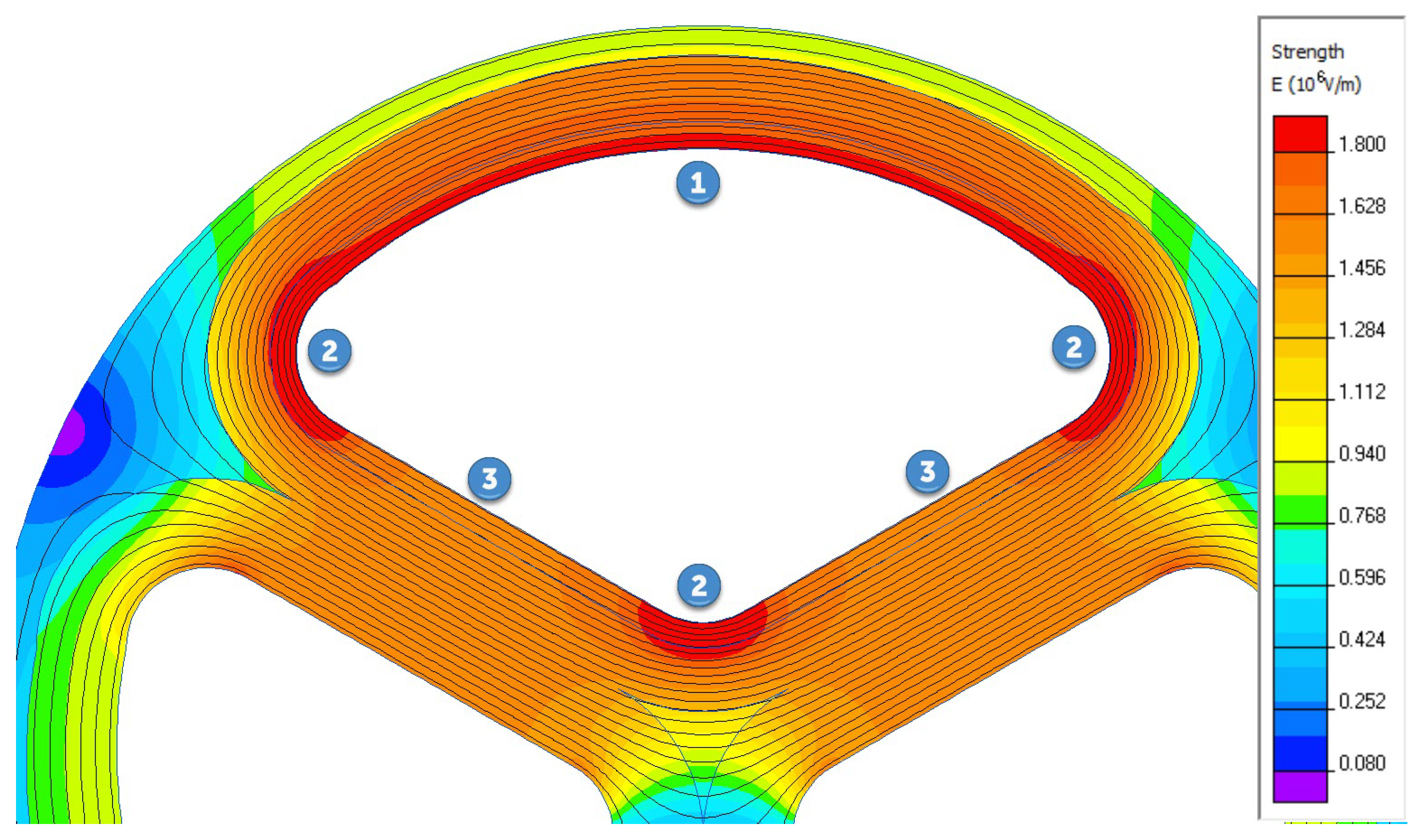
A three-phase cable with sector-shaped conductors is essentially a three-dimensional structure. Because the purpose of this analysis is to capture the effect of insulation design on cable properties, the model inevitably includes geometric elements with typical dimensions that differ by several orders of magnitude. Thus, the ratio of the of the laminated paper width w mm to its thickness mm is 4500:1. Three-dimensional modeling is a significant geometric challenge with this size ratio, although it can be overcome by replacing the three-dimensional model with a series of interconnected two-dimensional calculations in the cross-section and longitudinal sections.
The electric field in the cross section of a three-phase cable at the time when the potential of phase A (above) reaches its maximum is shown in
Figure 1. Such field pattern is typical for three-phase cables with sector-shaped conductors, regardless of the insulation type.
When switching to two-dimensional modeling in the longitudinal section, it is necessary to reduce the problem to an axisymmetric structure [
17]. For a round core, this is not a problem if the helicoidal structure of the tape winding and the variable winding direction are ignored.
Separate models are required for a sector-shaped conductor for characteristic insulation zones (zone 1 with a larger radius, zone 2 with a smaller radius, and zone 3 with an infinitely large radius). Because the cable insulation contains dozens or hundreds of periodically repeated layers of laminated paper separated by gaps filled with impregnating oil, it is sufficient to include a small number of PPLP tape layers in the model. Furthermore, in order to calculate the electric conductivity of the insulation, we consider a homogeneous insulation with an average conductivity derived from the model.
The model uses the following properties of dielectric materials (
Table 1).
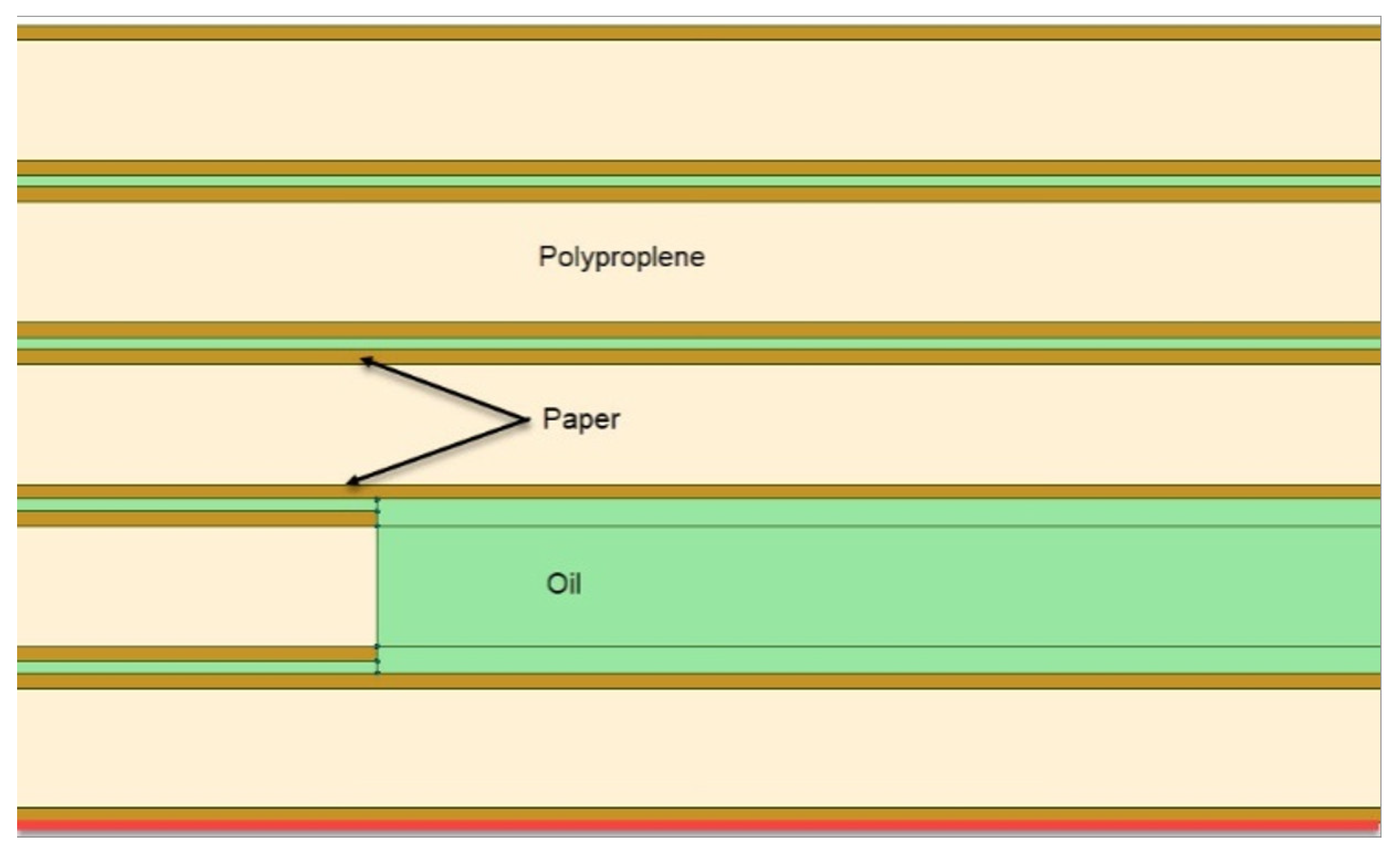
Including five or six layers of laminated paper in the longitudinal sections, with butt and radial gaps between them, we obtain the model, a sketch of which is shown in
Figure 2. Polypropylene layers are shown in dark yellow, layers of impregnated paper in pink, and oil-filled gaps between the tapes in light green, with 0.1 mm thick radial gaps and 2 mm wide butt gaps.
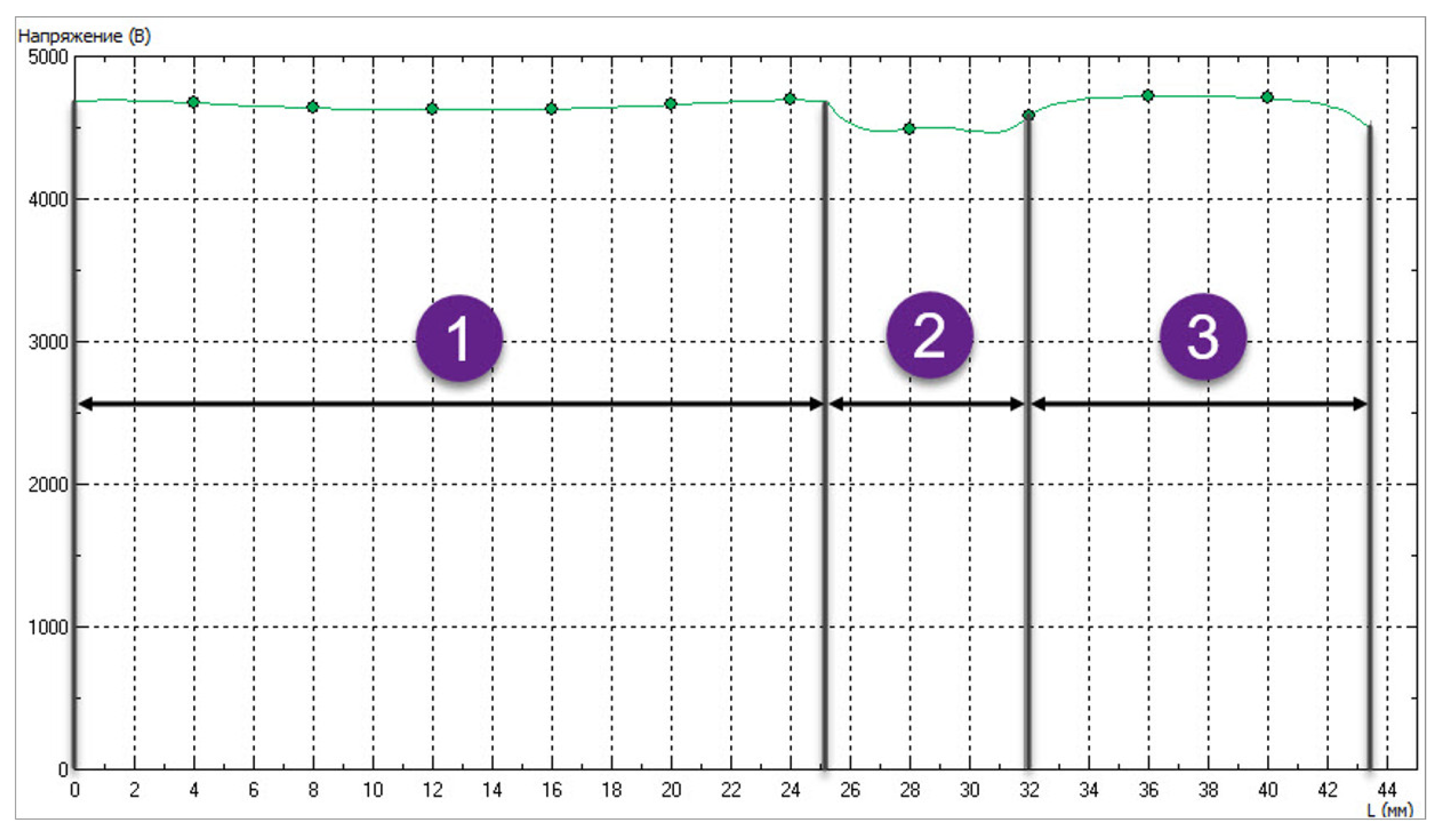
The bottom layer of the paper is in contact with the conductive core; thus, the potential at the lower boundary is equal to the phase voltage. The potential on the upper bound of the modeled fragment is slightly different for zones 1, 2, and 3. Its average value for a zone (
Figure 3) can be easily extracted from the field pattern in the cross-section (
Figure 1).
The axisymmetric model of insulation in zones 1, 2, and 3 differs both in the value of the potential at the upper boundary and in the radius of the inner layer, which corresponds to the conductor surface. For section 1 this is a larger radius equal to 17.45 mm, for section 2 the rounding radius of the sector-shaped core is 2.5 mm, and for section 3 the radius takes an infinite value, that is, we are considering a plane-parallel model instead of an axisymmetric one.
For each of the three longitudinal models, the average insulation conductivity is calculated according to Formula (2) for the axisymmetric problem or (3) for the plane-parallel problem:
where
is the applied voltage,
I is the insulation leakage current,
is the longitudinal length of the model, and
,
are the inner and outer radii of the model, respectively.
The average electrical conductivity of the insulation can be estimated as a weighted average of the electrical conductivities over the three zones, with the perimeter of the corresponding part of the sector-shaped conductor selected as the weight (
Table 2).
The weighted conductivity of the sector-shaped core is 2.57 × S/m. The same value calculated for the round core of equal cross-sections is 1.1 × S/m, which is 57% less.
The specific feature of the geometry is that it contains rectangles (paper layers) with a width-to-height ratio on the order of (4 … 5) ×
. The generation of a high-quality mesh of triangular finite elements in such a model requires an analysis of the mesh convergence (
Figure 4).
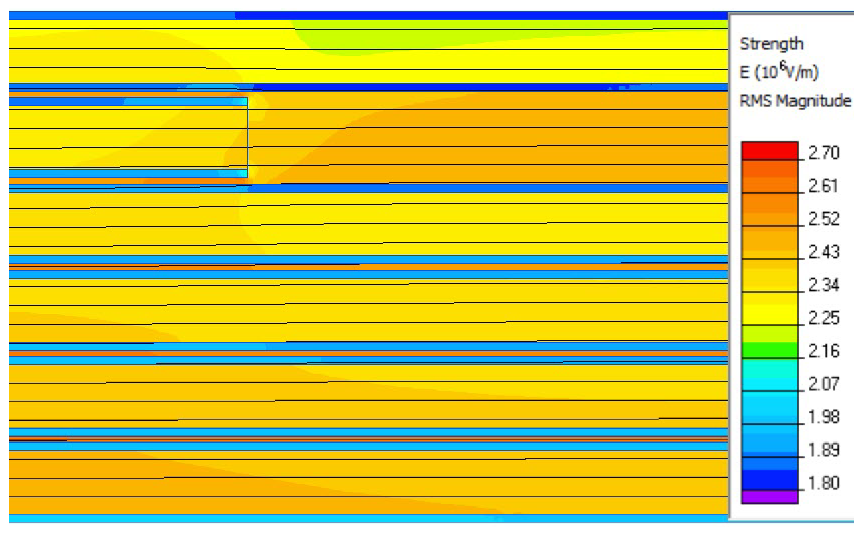
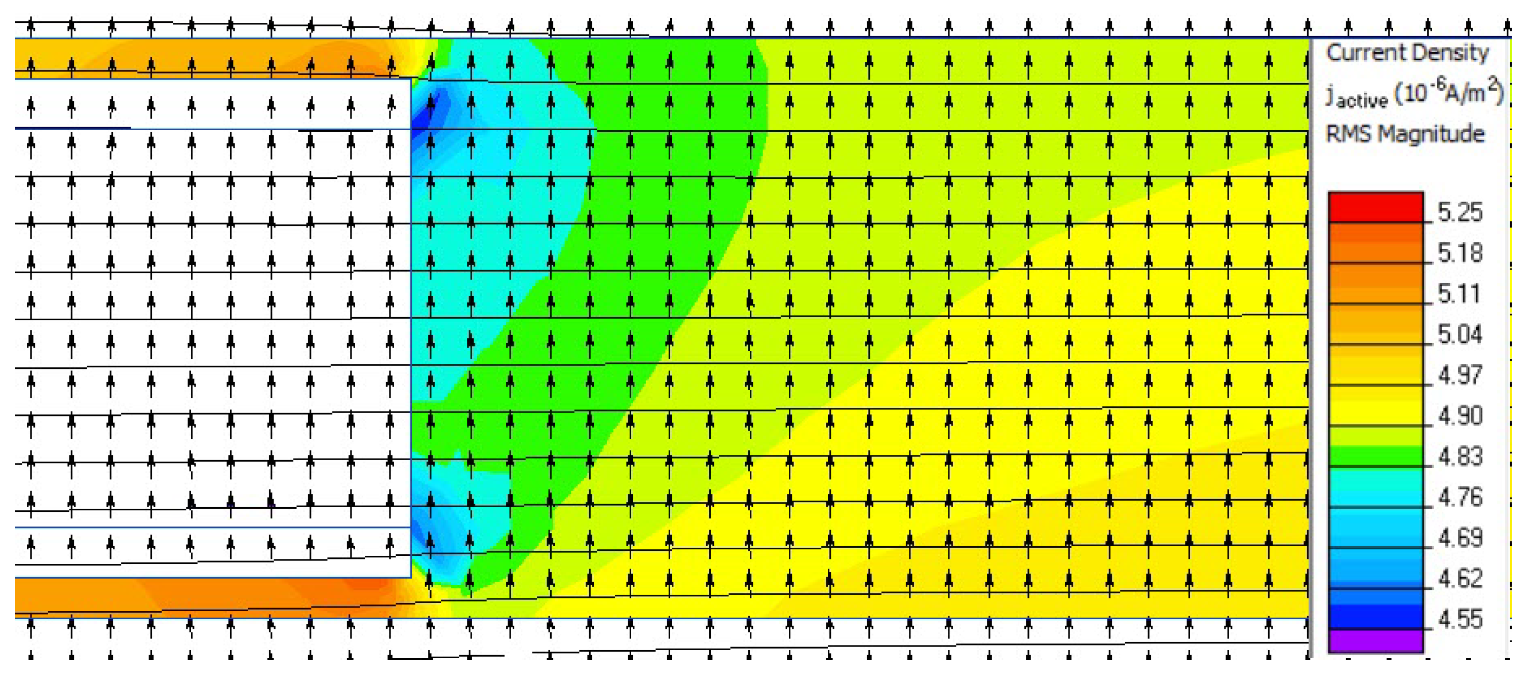
The solution of the problem on a series of finite element meshes with increasing density shows stable results with respect to the mesh density. The map of the leakage current density
J in the vicinity of the oil-filled butt gap is shown on
Figure 5 and
Figure 6.
The proportion of typical current density values in the different insulation layers is shown in
Table 3.
Table 3 shows that the leakage current flowing through the insulation is largely determined by the mutual arrangement of the oil gaps between the laminated tapes and their dielectric properties, mainly conductivity. Carrying out a series of calculations at different possible locations of longitudinal gaps in neighboring layers allows us to predict the integral conductivity of the insulation as a whole.
For this purpose, a series of calculations was performed at different shifts of winding layers relative to each other. The value of the shift varies from 0 to 3 mm, which corresponds to 0 … 1.5 of the longitudinal gap. Zero shift is the marginal case when the joint gaps are on top of each other, whereas a shift of 3 mm is one and half times larger than a longitudinal butt gap. Simulations were performed on the round core.
Table 4 shows that with realistic values of the shift of the winded layers relative to each other, the conductivity dependence on this factor is negligibly small. When the conductivity of insulation materials increases (polypropylene to 1 ×
S/m; paper layers and impregnating compound to 2.0 ×
S/m), the total insulation conductivity and current density in the gaps both increase by more than an order of magnitude, although the general laws described above persist. Therefore, the presented modeling technique is applicable in a wide range of values of the specific conductivity of cable insulation components.
3. Analytical Solution
The numerical simulation described above suggests that instead of calculating the parameters of a complex cable insulation system, simple analytical expressions can be developed to estimate the electrical resistance of the cable insulation using only a one- or two-dimensional model.
We use the following notation:
w is the width of the laminated paper tape,
g is the longitudinal butt oil-filled gap,
is the thickness of the polypropylene layer in the middle of the tape,
is the thickness of the paper layer on each side of the tape,
is the offset of butt gaps between tapes in neighboring tape layers, and
is the winding angle. We assume that the insulation is wound in one direction. Now, we consider the unfolding of one turn of insulation on the plane. The perimeter
of one turn equal to the perimeter of the gap is
where
is the radius of the turn. The value of
depends on the number of times the tape is turned in the insulation.
For three-core cables with sector shaped conductors, the insulation perimeter should be divided into two components:
is the perimeter of the phase insulation, which defines the insulation resistance between the conductive cores, and
is the perimeter of the inner covering, which defines the resistance between the conductive cores and the cable shield. Ignoring the rounding of the conductive core, the perimeter of the phase insulation can be estimated as follows:
The perimeter along the conductor is
and its perimeter along the outer surface of the phase insulation is
The current flowing through the insulation is determined by the conductivity of the PPLP tape in the radial direction as well as the conductivity along the oil-filled gaps, both butt and radial. Assuming that the location of the gaps between the tapes is random, these currents can be considered independently.
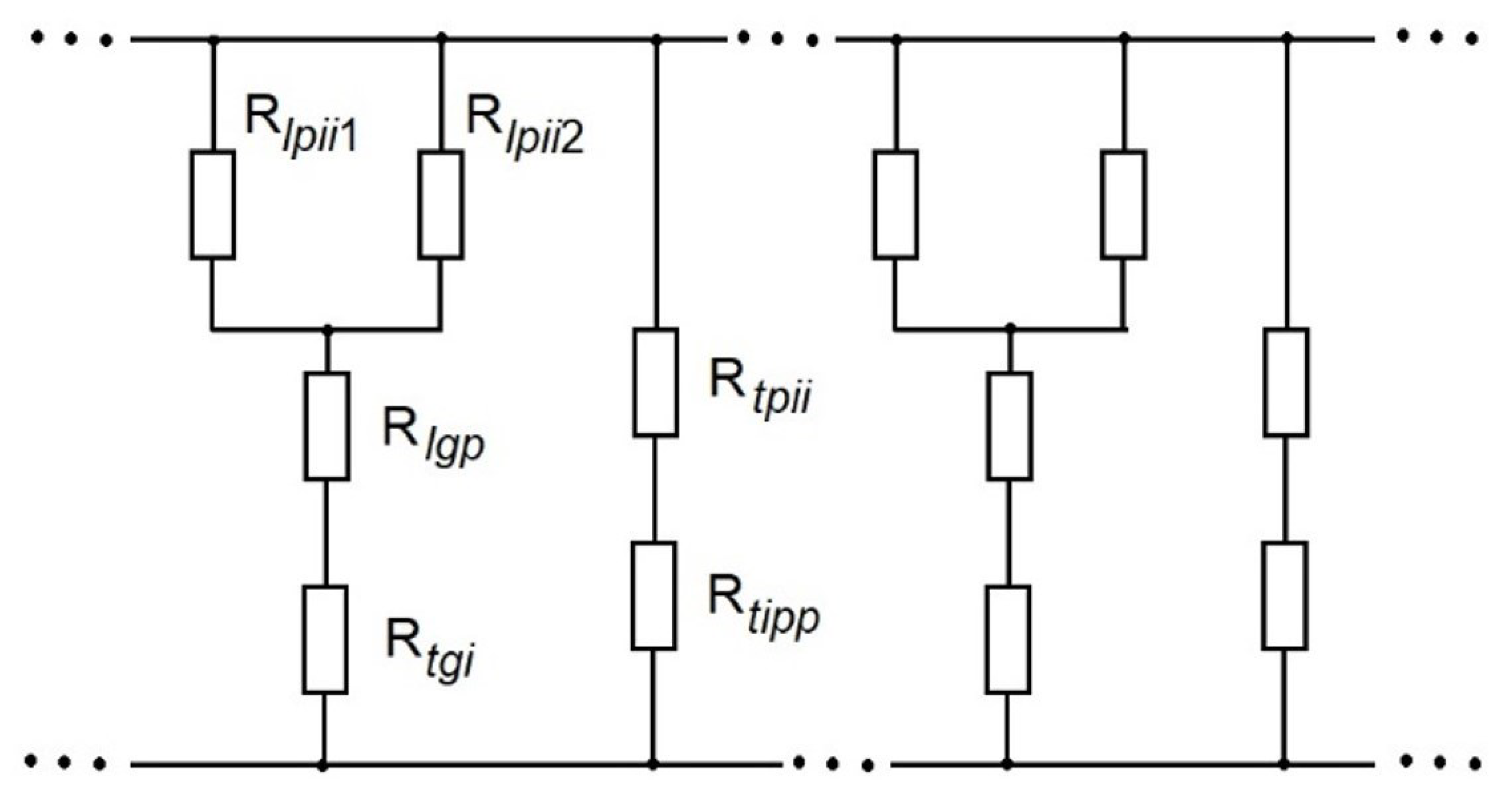
Equivalent circuit for one layer of PPLP insulation can be represented in the form shown in
Figure 7 when calculating insulation resistance. The elementary cell of the equivalent circuit is presented by two parallel branches,
and
, as shown in
Figure 7. Resistance
represents the through current flowing through the polypropylene layer and the impregnated paper, while
represents the current through both the radial and butt oil-filled gaps. This approach is an approximation, as the current flowing through the gap between the tapes affects the potential distribution in the impregnated paper layer (
Figure 6). Nevertheless, assuming
and the random distribution of the butt gaps in different layers, this influence can be neglected.
Below, we use the following notations for resistances:
—polypropylene;
—impregnated paper;
—radial oil-filled gap between tapes;
—impregnated paper between two neighboring oil gaps by
;
and
—impregnated paper between polypropylene layers by two sides of the oil gap.
where the
,
,
denote the electric conductivity of the polypropylene, impregnated paper, and impregnating oil, respectively. This model assumes tight wrapping of the insulation tape, i.e., zero gap between tapes, which corresponds to the distance between polypropylene layers being equal to twice the thickness of the paper layer. If
is assumed, the model is applicable for nonzero distances between insulation layers with formally increasing
.
Then, the tape conductance is
and the oil gap conductance is
After a few transformations, we have
The elementary cell conductance
is a sum of
The conductance of multiple elementary cells
by the length
in the case of
can be estimated as follows:
For the 2D approximation (a plane tape), the insulation resistance
with a thickness of
(at
, taking into account (14), can be calculated as follows:
For the sake of comparison, we can calculate the resistance of the same tape
made from paper without any lamination. It can be estimated as
Taking into account the cylindrical (i.e., not a plane) shape of the conductor, we consider the change of the perimeter of a tape turn
due to its the dependency of the layer’s radius. Because
and
are directly proportional to the perimeter
, we can introduce normalized quantities:
To calculate the resistance of cable insulation, we need to integrate over the radius of the insulation layers. Considering (1), we obtain
where
is the conductor radius. For a three-phase cable with sector-shaped conductors, the phase-to-phase resistance
is estimated as follows:
and the resistance between all conductors and the screen
is
where
is a coefficient which accounts for the decrease in the conductor’s perimeter compared to the length of the circumference due to the presence of phase insulation (
):
Equation (
21) estimates the maximal resistance value; thus, with
it provides the minimal estimation.
The resistance values calculated by the above formulas can be compared with the classically calculated resistance of round-shaped conductors as follows:
where
is the electric conductance of the insulation and
is the insulation thickness.
4. Calculation and Experimental Results
The experimental study was carried out on sections of power cables with three sector-shaped conductors with common lead jacketing. The testing voltage was 3.5 kV DC. The rated AC voltage was 10 kV, with a 240 mm conductor. The length of the section was chosen as 0.3 m with sealed ends. The cable samples were placed in low temperature oven “SNOL 58/350” with the temperature measurement accuracy of 0.1 °C, maintenance accuracy—0.5 °C. The current flowing through the insulation and electrical resistance were measured using a “METREL MI 3200 (10 kV) TeraOhm” teraohmmeter. The measurements were carried out after equalizing the temperature of the cables and the temperature internal air of the oven. We considered the moment when the equilibrium temperature was reached as the moment of stabilization of the insulation resistance and the current flowing through it at a constant air temperature in the oven. Sample 1 was a classical paper mass-impregnated insulation; the thickness of the phase insulation was 2.75 mm and the thickness of the inner covering was 1.25 mm. Sample 2 was a PPLP mass-impregnated insulation with the same thickness.
We performed both numerical simulation and calculation of insulation electrical resistance using the analytical model for the above insulation data.
The specific electrical resistance of the insulation (which provides the calculated according to (23) whether or not the factor is taking into account) that approximately corresponds to the measured value (see below) can be estimated as 0.5 × Ω·m. According to this calculation, the cable insulation resistance per 1 km length is 20 MΩ. At = 100 µm, = 10 µm, w = 55 mm, g = 1 mm, = , and in range (0.1 … 2)·, Ω·m and 0.5 × , = 0.5 × Ω·m, the calculated resistance per 1 km length provides a result of = 270 MΩ. Looking at the resistances of an elementary cell, ot os apparent that and and are much bigger then . This means that the insulation resistance is mostly defined by the resistance of the polypropylene layer.
With increasing tape width w and moderate decreasing of the gap between tapes g and the distance between tape layers, the influence of the current flowing in the longitudinal direction along the tape surface increases. Nevertheless, for the above-mentioned parameters, this influence can be neglected. Therefore, despite the high density of longitudinal currents and current in the gap between the tapes (as shown by our numerical simulations), there is no significant effect on the total electrical resistance of the cable insulation. Furthermore, winding angles within a reasonable range do not have a significant effect on the calculated resistance.
The theoretically calculated resistance (23) for a homogeneous polypropylene insulation (with no paper) is = 370 MΩ per km.
We measured the insulation resistance between three connected phase conductors and the electric screen at temperatures of 22, 50, and 90 °C. The measured values of the insulation resistance per 1 km are 20 MΩ, 7 MΩ, and 0.2 MΩ for the Sample 1 and 300 MΩ, 60 MΩ, and 2 MΩ for the Sample 2. By comparison with the calculated values of 19 MΩ and 270 MΩ, we can conclude that the calculation results agree well with the measured data.
5. Discussion
The low resistance value of the insulation of the classic paper-impregnated cable (Sample 1) is presumably due to moisture penetration into the insulation during the manufacture of the sample for the study. The electrical resistance of laminated paper insulated cable (Sample 2) complies with current national standards. Nevertheless, the electric conductivity of the material used here for calculation ( = Ω·m) is lower than the material from reference handbooks ( … Ω·m). With polypropylene insulation, moistening cannot be a reason for lowering of the . Instead, this results from the properties of the insulation material.
Our numerical, analytical, and experimental evaluations show that the effect of current flowing along the impregnated tape in the paper and impregnating oil is relatively small. Therefore, the magnitude of the longitudinal shift of the winding layers relative to each other weakly affects the conductivity of the insulation, which is indicated and justified in [
12]. This evaluation can be further confirmed by comparing the total insulation resistance of laminated paper and the theoretical homogeneous bulk polypropylene insulation (with no paper). As a result of these calculations, we found that for typical parameters of PPLP insulation components (such as those provided in
Table 1) and winding parameters of the insulation tape, the calculated difference in the resistance of PPLP insulation using the above analytical expressions from the theoretical resistance of bulk polypropylene insulation does not exceed 10–30%.
However, we can assume that with aging of the impregnation compound, higher temperatures, and insufficiently tight tape wrapping, the above effect may be significant or even dominant. For example, the calculated insulation resistance decreased by more than three times for when increasing the radial gap between the polypropylene layers to 200 µm and decreasing the resistivity of the impregnated paper to Ω·m.
According to [
21,
22], the temperature dependence of the resistivity
of PPLP insulation, is described by the expression
where
T is the temperature of the insulation,
E is the electric field strength in kV/mm, and
,
,
p are the coefficients determined by the properties of the material. Because all three insulation resistance measurements are made at the same voltage, it can be assumed that the resistance
is proportional to
, and
is a linear function of
T with the proportionality coefficient
. The experimentally measured value in [
21] was 0.06 K
−1. The estimated value of
for the three experimental points obtained in this work was 0.07 K
−1, which can be considered a fortunate coincidence, as the PPLP insulation, the impregnation composition of the cables, and the cables themselves were presumably prepared by different manufacturers.
6. Conclusions
This paper proposes a numerical model of mass-impregnated laminated paper cable insulation (PPLP) in which part of the insulation is considered as a continuous medium. The proposed model considers several layers of insulation in accordance with the real geometry, including the thickness of the polypropylene and paper and the size and location of oil-filled gaps. The proposed model avoids the complexity of three-dimensional modeling without loss of generality and without reducing calculation accuracy.
Modeling of the electric field and current density in the paper-plastic insulation using Finite Element Analysis showed that, despite some dependence of insulation parameters on the mutual arrangement of oil-filled gaps between insulation tapes, the electrical resistance of insulation can be calculated using the approximations discussed in this paper.
The electric field and current density distribution is such that the complex three-dimensional insulation design of cables with sector-shaped conductors, as well as cables with a round conductor, can be reduced to an equivalent flat model, the parameters of which can be calculated analytically.
Experimental data confirm the reliability and sufficient accuracy of the adopted approximations as well as the obtained analytical expressions.


