Review

Progress of Performance, Emission, and Technical Measures of Hydrogen Fuel Internal-Combustion Engines

State Key Laboratory of Engines, Tianjin University, Tianjin 300354, China
*
Author to whom correspondence should be addressed.
Energies 2022, 15(19), 7401; https://doi.org/10.3390/en15197401
Submission received: 4 September 2022 / Revised: 2 October 2022 / Accepted: 4 October 2022 / Published: 9 October 2022
(This article belongs to the Special Issue Advanced Research on Fuel Cells and Hydrogen Energy Conversion)

Abstract

:
To achieve the goals of low carbon emission and carbon neutrality, some urgent challenges include the development and utilization of low-carbon or zero-carbon internal combustion engine fuels. Hydrogen, as a clean, efficient, and sustainable fuel, has the potential to meet the abovementioned challenges. Thereby, hydrogen internal combustion engines have been attracting attention because of their zero carbon emissions, high thermal efficiency, high reliability, and low cost. In this paper, the opportunities and challenges faced by hydrogen internal-combustion engines were analyzed. The progress of hydrogen internal-combustion engines on the mixture formation, combustion mode, emission reduction, knock formation mechanism, and knock suppression measures were summarized. Moreover, possible technical measures for hydrogen internal-combustion engines to achieve higher efficiency and lower emissions were suggested.

1. Opportunities for Hydrogen Internal-Combustion Engines

Environmental issues and global warming have become more prominent and critical in the past few decades. To solve these problems, the Paris Agreement reached a consensus and decided to attempt to slow the progress of global warming processes in December 2015, the goal of which being to control the increasing global rising temperature to within 2 °C in the 21st century. Therefore, many countries have been proposing and implementing carbon-reduction and carbon-neutrality strategies. At the 75th session of the United Nations General Assembly (September 2020), China proposed a double carbon target of peaking carbon dioxide emissions by 2030 and achieving carbon neutrality by 2060 and introduced a series of policies to promote the process of carbon reduction, creating a strong demand to decarbonize not only transport sectors, but also the power industry, incentivizing away from conventional carbon-based fuels and towards renewable energy sources. Hydrogen can be produced from several varieties of renewable energy sources and efficiently obtained through large-scale electrolysis. And after its reaction with oxygen, water is produced. Additionally, hydrogen combustion or electrochemical reactions can be used to generate thermal or electric energy as power sources for cars. Although hydrogen is less portable and has a lower volumetric energy density than liquid fuels, it has proven itself as having the highest mass-specific energy density among general fuels, such as gasoline, diesel, methanol, ethanol, and so on.
Up until now, hydrogen has been bridging the low-carbon economy and renewable energy, which suggests its key role in preventing global warming. Many countries have begun to produce hydrogen. According to the International Hydrogen Energy Commission’s statistics, 228 projects in the global hydrogen energy industry chain have been built, and more than 20 countries and regions, such as the United States, Japan, the European Union, South Korea, and New Zealand, have issued hydrogen energy-development strategies [1]. In December 2021, China’s Ministry of Industry and Information Technology issued the Industrial Green Development Plan, a proposal to accelerate hydrogen energy technology innovation and infrastructure construction and promote the diversified use of hydrogen energy.
At present, the use of hydrogen energy in the power vehicle industry mainly includes fuel cells and internal-combustion engines. Hydrogen fuel cells are high-efficiency electrochemical devices that directly convert chemical energy into electric energy and only produce water as a by-product without any other harmful emissions. However, hydrogen fuel cells have a disadvantage in terms of their cost and service life, and the prices of fuel cell vehicles are still much higher than those of traditional vehicles [2]. Based on the abovementioned reasons and combustion characteristics of hydrogen, it is attractive as a fuel for internal-combustion engines. Extensive literature studies have shown that hydrogen, as a fuel for internal-combustion engines, has a wider flammable range, the ignition limit range of which expressed by the air–fuel ratio is 0.14 to 10, the minimum ignition energy required is one-tenth of that of gasoline fuel, and the laminar flame velocity is more than six times faster than that of conventional fuels. Hydrogen also has a higher diffusion coefficient, lower ignition energy, and wider flammability limit, which, when compared with conventional fuels, result in better heat and mass-transfer characteristics, better lean-burn characteristics, and lower misfire rates, as can be seen in Table 1 [3,4,5,6].
The lower heating value of hydrogen is much higher than that of gasoline and natural gas. Combining faster laminar flame speeds, lean-burn characteristics, and higher spontaneous combustion temperatures makes hydrogen internal-combustion engines have a high thermal efficiency and potential knock resistance. Hydrogen has a shorter quenching distance, which is about one-third that of gasoline and methane. This affects crevice combustion and wall-heat transfer [3]. In addition, the wide flammability limit enables hydrogen-fueled SI engines for quality control such as diesel engines, rather than volume control at fixed fuel–air mixture conditions close to stoichiometric ratios, as is the case in regular gasoline engines. This ensures that hydrogen engines have a higher indicated thermal efficiency than gasoline engines [9,10,11].
Compared with fuel cells, hydrogen internal-combustion engines can take advantage of the mature industrial chain and technology of existing internal-combustion engines, and only need to optimize the fuel supply and injection system, turbocharger matching, lubrication system, and crankcase ventilation [12]. Moreover, the purity of hydrogen is not strictly required; the byproduct of industrial hydrogen can be used, resulting in a lower user cost while fuel cells need high-purity, hydrolyzed hydrogen at the current stage and the cost is relatively high. Thus, hydrogen is an ideal alternative fuel for internal-combustion engines, which, in turn, assists the optimization and development of new energy technologies with hydrogen internal-combustion engines.

2. Research on Performance Improvement of Hydrogen Internal-Combustion Engines

Companies such as BMW and Ford Motor have been developing hydrogen fuel internal-combustion engine vehicles, and they have successfully demonstrated their excellent performance in terms of emissions and fuel economy [13,14,15,16,17]. BMW tested a specially designed engine with an external and internal mixture formation system to study the effect of different injection strategies on hydrogen engine performance [13,14]. The experimental results showed that the hydrogen engine, combining the external and internal mixture formation systems, can operate efficiently under partial load and lean-burn conditions. Stoichiometric mixture can be achieved even when operating at full load through external mixture formation or direct injection. For BMW’s operating strategy with a post-treatment catalyst to reduce emissions, using the lean mixture is only suitable for low-load engine conditions, while the stoichiometric mixture is suitable for high-load engine conditions. The average indicated pressure of the engine reached 1.8 MPa at 4000 rpm engine speed, which is higher than that of the basic gasoline engine.
A test for two BMW Hydrogen 7 Mono-Fuel demonstration vehicles was completed in 2008 [15]. The two vehicles were tested at the FTP-75 cold-start as well as the highway drive cycle, respectively, achieving fuel economy performances of 3.7 kg of hydrogen per 100 km on the FTP-75 cycle and 2.1 kg of hydrogen per 100 km on the highway cycle. These results are, respectively, equivalent to 13.8 L per 100 km and 7.8 L per 100 km for gasoline fuel consumption at the FTP-75 cold-start and highway drive cycle. These emission results on the FTP-75 cycle showed that emission levels are inferior to 0.0008 g/mile of nitric oxide (NOx) emissions, 0 g/mile of nonmethane hydrocarbon (NMHC) emissions, and 0.003 g/mile of carbon monoxide (CO) emissions. These emission results are equivalent to the Super Ultra Low Emissions Vehicle (SULEV) emission levels, which are 3.9% NOx, 0% NMHC, and 0.3% CO.
Ford motor company built and tested the first production-ready vehicle, the P2000, with a hydrogen internal-combustion engine that could run without throttle on a lean mixture [16,17]. The research team of Argonne National Laboratory evaluated several direct-injection hydrogen mixture formation strategies to reduce NOx emissions and achieve a higher thermal efficiency of the engine. The group carried out engine experiments under the speed range of 1000~3000 rpm and the average effective pressure range of 0.17~1.43 MPa [18,19]. The results showed that the effective thermal efficiency (BTE) was more than 35% under about 80% of test conditions. There was a balance between wall-heat loss and other losses as a function of engine speed and load. Therefore, the peak effective thermal efficiency of 45.5% and NOx emission of 0.87 g/kW·h were obtained at 2000 rpm and BMEP of 1.35 MPa. However, NOx emissions increased with the increase in speeds and loads, which means that the mixture formation needs to be further optimized.
Due to the potential of hydrogen as a flexible energy carrier, the development projects of large hydrogen internal-combustion engines based on diesel engines have also begun to emerge in recent years. The group of National Traffic Safety and Environment Laboratory and Tokyo City University has developed a large (medium load) truck with a multi-cylinder, spark-fired, direct-injection hydrogen engine [20]. The engine was developed for the project based on a four-cylinder diesel engine with a displacement of 4.73 L. A low NOx emission (0.7 g/kW·h), IMEP of 0.85 MPa, and indicated thermal efficiency (ITE) of 41% were obtained under the adopted combustion control strategy and the engine operating conditions. The torque was about 20% lower than that of the base diesel engine. The torque deficit of the hydrogen engine can be improved by boosting the intake air, but it is necessary to avoid pre-ignition and knock.
In order to achieve sufficiently low NOx emissions, high thermal efficiency and high torque without any post-treatment conditions. A study on large-scale hydrogen internal-combustion engines for stationary power generation was conducted in the Renewable Energy Research Center, National Institute of Advanced Industrial Science and Technology, Japan [21]. Experimental studies were carried out by changing the piston design, adding a spark plug, and adding a direct-injection hydrogen injector on a single-cylinder diesel engine with a displacement of 1.3 L. In the absence of a post-treatment system, an extremely high EGR rate and intake boost with suitable hydrogen mixture formation strategies were used to achieve NOx emissions below 200 ppm. The ideal IMEP is above 1.35 MPa (140 Nm) at 1000 rpm, reaching the level of a benchmark diesel engine. Distinct from previous research on the injection strategy of the direct-injection hydrogen engine, it is proposed to set the injection pressure at a lower level through small-hole injection, which attempts to produce the stratification of the hydrogen mixture in the engine cylinder. Although low injection pressure and long hydrogen-injection time may lead to the increase in mixture inhomogeneity, there is a trade-off between the equivalent ratio and NOx emissions. In this study, lower NOx and higher ITE could be achieved when the global equivalent ratio was kept around 0.3. By analyzing the effect of EGR on combustion performance, it was found that the EGR rate had only a slight effect on combustion performance. No matter how large the EGR rate is, the indicated thermal efficiency, the average indicated pressure, as well as CA50 were essentially unchanged. However, increasing the EGR rate could significantly reduce nitrogen oxide emissions. In addition, it can be concluded that the inhomogeneity of the hydrogen mixture in the cylinder, results in robust combustion, which is not sensitive to the EGR rate. Experiments suggested that the maximum IMEP was 1.46 MPa, the engine NOx emission was less than 150 ppm, the boosting pressure was 175 kPa, the oxygen concentration of the intake air was 12.5 vol%, and the corresponding EGR rate was about 50%. To further improve IMEP and thermal efficiency without increasing NOx emissions, Atkinson/Miller cycles were used to attempt to delay the intake valve closing and exhaust valve opening to reduce the effective compression ratio and increase the effective expansion ratio. The IMEP eventually reached 1.64 MPa, NOx emissions were below 100 ppm, and the ITE was more than 50%.
In order to increase the power output and reduce NOx emissions, Verhelst’s research group studied an in-cylinder direct-injection hydrogen internal-combustion engine equipped with EGR and a turbocharger under lean-burn and stoichiometric mixture conditions [22,23]. Comparing the performance of lean-burn without post-treatment and stoichiometric mixture conditions with both EGR and the post-treatment system, it was found that lean-burn combined with a turbocharger is the more effective method for achieving higher efficiency and lower NOx emissions. Clearly, to avoid abnormal combustion and unacceptable levels of NOx emissions, lean burns require higher boosting pressures for keeping the equivalent ratio enough low. Otherwise, lean-burn operation of the engine will inherently result in insufficient torque or power. On the other hand, a power output higher than 30% of gasoline can be achieved when selecting a supercharged stoichiometric mixture with EGR, but fuel economy is sacrificed by catalytic post-treatment with NOX removal.
By changing the hydrogen-injection timing, homogeneous mixture combustion, stratified combustion, and diffusion combustion can be realized in hydrogen internal-combustion engines. Toyota Motor Corporation conducted experimental research in a 2.2 L four-cylinder diesel engine equipped with a centrally mounted hydrogen injector, a toroidal shape combustion chamber, and a spark plug in the glow-plug position [24]. The research investigated the high efficiency and low NOx of hydrogen combustion using a prototype high-pressure hydrogen injector (maximum 30 MPa). In addition, stratified combustion and spark-assisted diffusive combustion was investigated, and the results showed that the pressure-recovery effect by injection close to TDC and EGR effectively combined with stratified and diffusive combustion by high-pressure direct injection greatly improved the indicated thermal efficiency by approximately 3% compared with conventional homogeneous combustion. Furthermore, suppressing jet penetration and reducing cooling loss, a 52% ITE was achieved for a small engine.
The Indian Institute of Technology research groups developed the stoichiometric or over-stoichiometric mixture-formation strategies, including cooled EGR, turbocharging, and NOx removal catalytic post-processing, to achieve higher torques and prevent abnormal combustion and high NOx generation [25]. Using unburned hydrogen as a NOx-reducing agent under stoichiometric conditions, a peak torque of 180 Nm was achieved at 3600 rpm with over 800 ppm NOx and a BMEP of approximately 0.9 MPa.

3. Port Injection and Direct Injection of Hydrogen

The hydrogen-injection methods of the hydrogen internal-combustion engine are divided into port fuel injection (PFI) and direct injection (DI) in the cylinder, but due to the small hydrogen density, the port injection will lead to a decrease in the intake efficiency, resulting in a significant decrease in power density. Direct injection in the cylinder can not only improve the intake efficiency and consequently result in a greater power density, but also avoid backfire compared with PFI, which can increase the power density by 38.4%. In addition, direct injection can also achieve a more flexible organization formation of the mixtures and, in turn, achieve a variety of combustion modes such as stratified combustion and homogeneous combustion or even diffusion combustion [24,26,27].
Due to gasoline and diesel fuel being liquid, injection causes little change in cylinder pressure. Therefore, the change in negative compression work due to fuel injection is negligible for gasoline and diesel fuel engines. However, for in-cylinder direct-injection hydrogen engines, hydrogen injection is generally carried out during the compression stroke, hydrogen will occupy a relatively large part of the cylinder volume, and the hydrogen injected has a large pressure, so it will cause an increase in compression pressure and negative compression work. However the negative compression work can be reduced by controlling the hydrogen-injection timing. Additionally, the thermal efficiency can be improved by optimizing the compression ratio and the phase of hydrogen injection. Compared with low-load uniform combustion, stratified combustion achieved by direct injection can achieve a high combustion constant volume degree, thus improving the engine efficiency. During engine operation, the combustion loss of port injection and direct injection is almost the same [28].
Compared with gasoline engines, the current port-injection and direct-injection hydrogen engines both have good effective thermal efficiency. Direct injection of hydrogen internal-combustion engines has more advantages in terms of power performance, fuel economy, and NOx emission, making it an ideal hydrogen-supply method. Compared with low-load uniform combustion, the stratified combustion can achieve a higher combustion constant volume, resulting in improved engine efficiency. The late injection strategy should be adopted to perform stratified combustion. Efficiency losses such as compression work, heat transfer to the coolant, and abnormal combustion should be reduced.
However, compared with direct-injection hydrogen engines, port-fuel-injection hydrogen engines have some disadvantages such as higher cooling loss, which results in low thermal efficiency and abnormal combustion (backfire, pre-ignition, higher burning velocity) leading to limited high-load operation. Direct injection is an effective method to overcome these disadvantages, but the combustion methods that enable both high efficiency and low NOx have not yet been thoroughly investigated.

4. Formation of the Hydrogen–Air Mixture

4.1. The Influence of the Structure and the Layout of the Hydrogen Injector on the Formation and Combustion of the Hydrogen–Air Mixture

As with gasoline direct injection and diesel engines, the structure and arrangement of injectors for hydrogen internal-combustion engines have a great impact on the mixture formation. There is no atomization process for hydrogen, so the hydrogen engine does not need too high injection pressure and too small nozzle diameter to ensure good atomization. However, the structure and arrangement of the nozzles directly affect the distribution of the mixture and the combustion performance.
Due to the low density of hydrogen, it is difficult for conventional nozzles to meet the flow requirements. For high-speed conditions, larger hydrogen-injection flow means a shorter injection duration, which is very important for implementing a more flexible injection strategy. Therefore, outward-opening nozzles are widely used. For the outward-opening nozzle, the near-field jet shape is conical, and the far-field jet shape is spherical [29]. However, the hole-injector can achieve a longer penetration length under the same conditions [30]. The penetration length of the jet is related to the injection pressure, nozzle structure, injection direction, and even the location of the injector [31]. However, compared with the injection pressure and other parameters, the penetration length is more sensitive to the nozzle diameter. Wang et al. [32] studied the effects of injection timing, nozzle diameter, and nozzle location on mixture formation by numerical simulation in a hydrogen port-injection engine. The results showed that the injection timing greatly influences residual hydrogen in the intake port. With the advancement of injection timing, residual hydrogen in the intake port gradually decreases and the possibility of backfire and pre-ignition is reduced. With later injection time, much of the concentrated mixture fails to enter the cylinder. In addition, the location of the hydrogen injector in the port also influences the injection timing. When the distance between the nozzle and the intake valve increases, the optional range of hydrogen-injection timing becomes narrower, and the optimal injection timing advances. When the diameter of the nozzle becomes smaller, the hydrogen-injection flow decreases, and thus the injection pulse width becomes longer and the amount of residual hydrogen in the intake port increases. When the diameter of the nozzle is too large, the amount of hydrogen returned from the cylinder to the intake port increases, so there is an optimal nozzle diameter to minimize the amount of residual hydrogen in the intake port.
Compared with hydrogen port injection, the location and direction of the hydrogen injector for the direct-injection engine have a greater influence on the formation and combustion of the hydrogen–air mixture. For the hydrogen direct-injection engine, the hydrogen injector may be located at the center or the side of the combustion chamber. Wallner et al. [33] found that, under low load conditions, the side arrangement of the hydrogen injector can increase the thermal efficiency by 4%. Additionally, the injection timing has a significant influence on the combustion duration at low loads. However, at high loads, the change of combustion duration at different injection timing is not more than 20%. In addition, the effect of injection timing on NOx is opposite under high and low loads [34]. Under low load conditions, the equivalence ratio is relatively low. With the delay of injection timing, the uniformity of the hydrogen–air mixture becomes worse, and the area of the rich mixture increases, resulting in the increase in NOx. When the load is high, the equivalence ratio is high. With the delay of injection, the generation of NOx is reduced due to the formation of lean or rich hydrogen–air mixture regions.
The effects of the hydrogen injector structure, including the number of nozzles and nozzle shape on the formation of the hydrogen–air mixture, were studied by the Salazar Research Group [35]. For the single-hole nozzle, the spatial distribution of the fuel cloud is relatively concentrated, and through the interaction with the cylinder wall, a circular motion similar to the tumble is formed, thus accelerating the hydrogen and the air mixing. For nozzles with 13 holes, hydrogen jets will collapse and merge. The dominant mechanism of the mixing process is the interaction of hydrogen jets and the cylinder wall, and a small amount of air will be entrained in the near field of combined jets. In addition, due to a part of the jets merging and the large-scale turbulence, if the cone angle of nozzle holes is too small, the near-field jet will be unstable.
At Tokyo City University [36], researchers tried to improve the thermal efficiency and further reduce NOx emissions to the level of several ppm by optimizing the injection direction, number, and diameter of jets and controlling injection timing. The injector can provide up to 20 MPa of injection pressure and multistage injection. In the test, to evaluate the engine performance, the five nozzle holes were arranged in a straight line so that the fuel was injected at injection angles of 15°, 25°, and 35° and injection diffusion angles of 60°. The experimental results showed that the injection direction greatly influenced the formation and combustion of the hydrogen–air mixture. Appropriately increasing the angle between the jet direction and the horizontal plane can separate the fuel jet and the combustion chamber wall, especially for late injection (SOI = 30° BTDC), and higher thermal efficiency and lower NOx emission can be achieved. Small nozzle-hole diameter can reduce the surface area of the jet, thereby increasing the air entrained by the jet, making the hydrogen more uniform in the jet, reducing NOx emissions and improving thermal efficiency. However, with the rise of the diameter of the nozzle hole, the hydrogen concentration gradient at the top of the hydrogen jet becomes smooth, which benefits ignition. If the shape of the nozzle outlet is conically flared, the surrounding disturbance will increase, and the radial diffusion will expand to form a larger flammable area [37]. When the injection process occurs in the intake stroke, the interaction between the intake flow and the hydrogen jet can be fully utilized to speed up the mixing process, which is conducive to forming a more uniform mixture. However, the nozzle location and injection direction need to be reasonably arranged [38].
By optimizing the hydrogen-injection direction, the number, and diameter of the nozzle holes, controlling the injection timing, and realizing the lean combustion, the thermal efficiency is greatly improved and the NOx emission is reduced to a very low level. Under the condition of the NOx emission remaining unchanged, the output power of the lean mixture can be recovered by boosting intake air, and the thermal efficiency can be further improved by the optimized hydrogen jet strategies [36].

4.2. The Influence of Hydrogen-Injection Timing on Hydrogen–Air Mixture Formation and Combustion

The earlier the injection timing is, the longer the mixing duration is, and the more uniform the mixture will be. Although the mixture is not uniform under the late injection condition, the stratified combustion can be realized through an optimization injection strategy so that the hydrogen–air mixture near the spark plug is rich enough to ensure the formation and development of the flame kernel. In comparison, the hydrogen–air mixture near the cylinder wall is leaner to reduce the heat-transfer loss and knock [39]. The flow field near the spark plug is affected by the injection strategy and the injection direction. When the injection direction is toward the spark plug, the early injection timing makes the injection complete before ignition, and after a long time of dissipation, the turbulent kinetic energy near the spark plug is low. On the contrary, the late injection will increase the turbulent kinetic energy and the hydrogen concentration around the spark plug [40].
Fan et al. [41] analyzed the influence of injection strategy, including injection timing and injection duration, on the mixture formation of a hydrogen rotary engine by using the numerical method. The results showed that when SOI is too early, the injection timing has little effect on the distribution of hydrogen. However, with the delay of SOI, the distribution of the hydrogen–air mixture becomes more sensitive to the injection timing, and the stratification of the hydrogen–air mixture is gradually obvious.
Kaiser et al. [42] used planar laser-induced fluorescence (PLIF) technology and particle image velocimetry (PIV) to test the concentration field and flow field distribution during the mixing process in a hydrogen direct-injection engine. The in-cylinder concentration distributions at different injection timings were compared. It is found that the distribution of the hydrogen concentration is closely related to the injection timing. For the early injection, the mixture in the cylinder was relatively uniform. For the middle injection, the mixture in the cylinder was relatively lean near the cylinder wall and rich in the central area. The lean hydrogen–air mixture near the spark plug directly caused the combustion phase later, and the peak pressure and the heat-release rate decreased. In addition, the tendency to knock was greatly increased due to the longer time of flame propagation and the richer concentration of the hydrogen–air mixture at the end of the cylinder.
The investigation results of Wimmer et al. showed that hydrogen direct injection allows for a more flexible injection strategy compared with port injection. Ignition timing of the hydrogen direct-injection engine had a minor influence compared with injection timing. In contrast, retardation of the injection timing resulted in mixture stratification. The tumble motion was established for late injection. As there was little time for homogenization, the mixture at ignition timing was highly inhomogeneous. This stratification with rich zones near the spark plug resulted in shorter combustion duration, and led to higher pressure rises during the early combustion phase. The late injection can not only reduce the negative compression work, but also achieve stratified combustion and increase the constant volume degree, which is beneficial to improve the thermal efficiency [43,44].
White et al. [45] used the PLIF method to measure the mixing process of hydrogen in a single-cylinder optical engine. The results showed that a more uniform mixture could be obtained by advancing the hydrogen injection before the intake valve is closed. The injection pressure had little effect on the mixture distribution during the process. However, with the delay in injection timing, the difference in the mixture distribution under different injection pressures was gradually obvious. Especially when the injection timing is late, the higher the injection pressure is, the faster the mixing rate is, and the greater the turbulence intensity of the whole flow field is. In addition, the distribution of the fuel–air mixture during late injection was affected by the location of the nozzle and the injection direction.
Keskinen et al. [46] studied the effects of the nozzle type, injection pressure, and injection timing on the formation of the fuel–air mixture and found that, compared with injection pressure, the mixing rate was more sensitive to the injection timing, and the interaction between the hydrogen jet and cylinder wall or piston under late injection conditions could significantly enhance the mixing rate. In addition, the mixing process was closely related to the nozzle type.
With the delay of the start of injection (SOI), the negative work of compression is reduced [44,45], and the stratification of the fuel–air mixture becomes more obvious due to the shorter mixing time. Optimizing SOI under the given engine operating conditions relies on the premise of guaranteeing sufficient mixing time; the hydrogen-injection time should be delayed as much as possible to obtain the minimum negative compression work. Without enough time for mixing, the engine operation will become unstable and the thermal efficiency will decrease. Figure 1 shows the optimal SOI sweeps based on the efficiency at different engine speeds (1700, 2000, 2500, and 3000 rpm) under high load conditions [19]. It can be seen that the optimal SOI increased linearly with the engine speed. The efficiency loss was reduced by delaying the hydrogen-injection timing to the compression stroke and forming a stratified mixture. The peak BTE was 45.3% at 2000 rpm, 1.35 MPa BMEP, and the part-load BTE was 32.9% at 1500 rpm, 0.2 MPa BMEP. Through further nozzle optimization, the H2-DI engine with the four-hole nozzle achieved a peak BTE of 45.5% and a part-load BTE of 33.3%. Compared with the five-hole nozzle, the mixture formed by the four-hole nozzle is more beneficial to reducing NOx emissions, especially at the maximum efficiency operating condition. The NOx emission in the map was mainly less than 0.10 g/kW·h.
According to the abovementioned research, injection timing has an important influence on the formation and combustion of mixture, and the optimal injection timing should change with different engine operation conditions. The advantages and disadvantages of early injection and late injection are summarized in Table 2.

5. Combustion Feature and Performance of Hydrogen Engines

5.1. Effects of Equivalence Ratio on Combustion and Performance

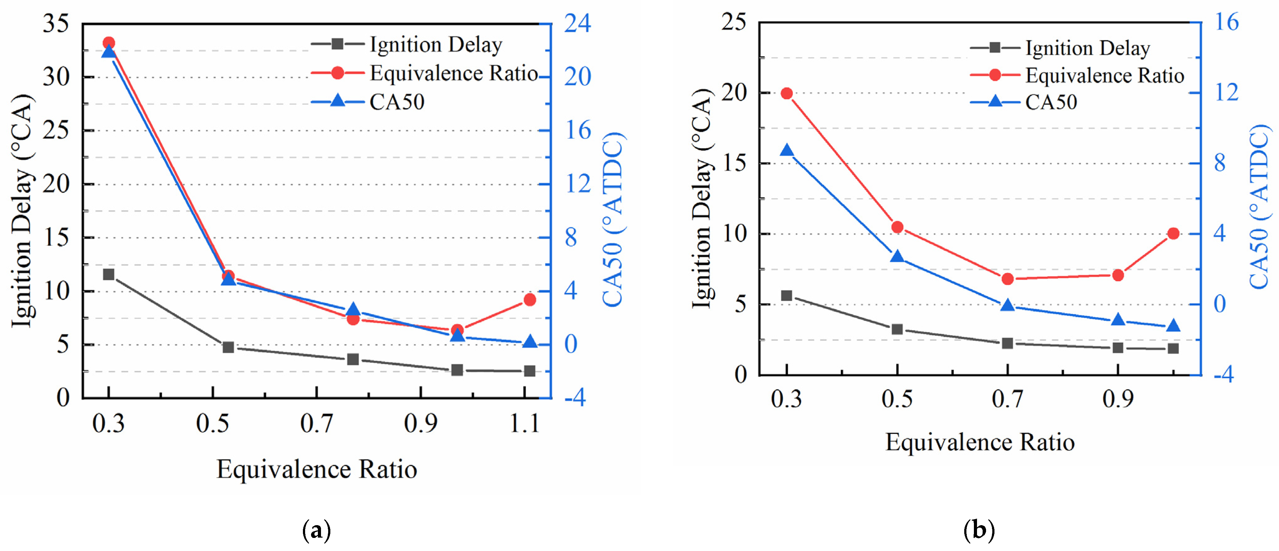
The most remarkable feature of hydrogen is its rapid combustion. Under normal temperature and pressure conditions, the laminar flame speed of hydrogen is about six times higher than those of gasoline and natural gas. Additionally, the combustion speed is greatly affected by the concentration of the hydrogen–air mixture. According to the different equivalent ratios, Li used a G equation with the piecewise laminar flame velocity model combined with a detailed chemical reaction model to simulate the combustion process of a hydrogen engine. Figure 2 shows the relationship of the ignition delay, combustion duration, and combustion phase (CA50) with the equivalence ratio under the working conditions in Table 3 [47]. In the simulation, the intake pressure, engine speed, and hydrogen-injection pressure were kept constant. The hydrogen-injection mass was adjusted by controlling injection pulse width to achieve the variation of the equivalence ratio. It can be seen from Figure 2 that with the increase in the equivalence ratio, the ignition delay and combustion duration gradually decreased, and the CA50 was advanced. When the compression ratio was 12, with the equivalence ratio increased from 0.3 to 0.5 the ignition delay and combustion duration were shortened by 6.8° CA and 21.8° CA, respectively. However, when the equivalence ratio was increased from 0.5 to 1.0, the ignition delay and combustion duration were shortened by a maximum of 2.1° CA and 5.1° CA, respectively. It can be concluded that the combustion rate is more sensitive to the equivalence ratio at a low concentration of the hydrogen–air mixture. When the equivalence ratio was higher than 0.7, the combustion rate’s increase was relatively stable, and the sensitivity to the concentration of hydrogen–air became low. When the compression ratio was 15, there was a similar trend, but the sensitivity of the combustion rate to the concentration of the hydrogen–air mixture was lower than that of the low compression ratio.
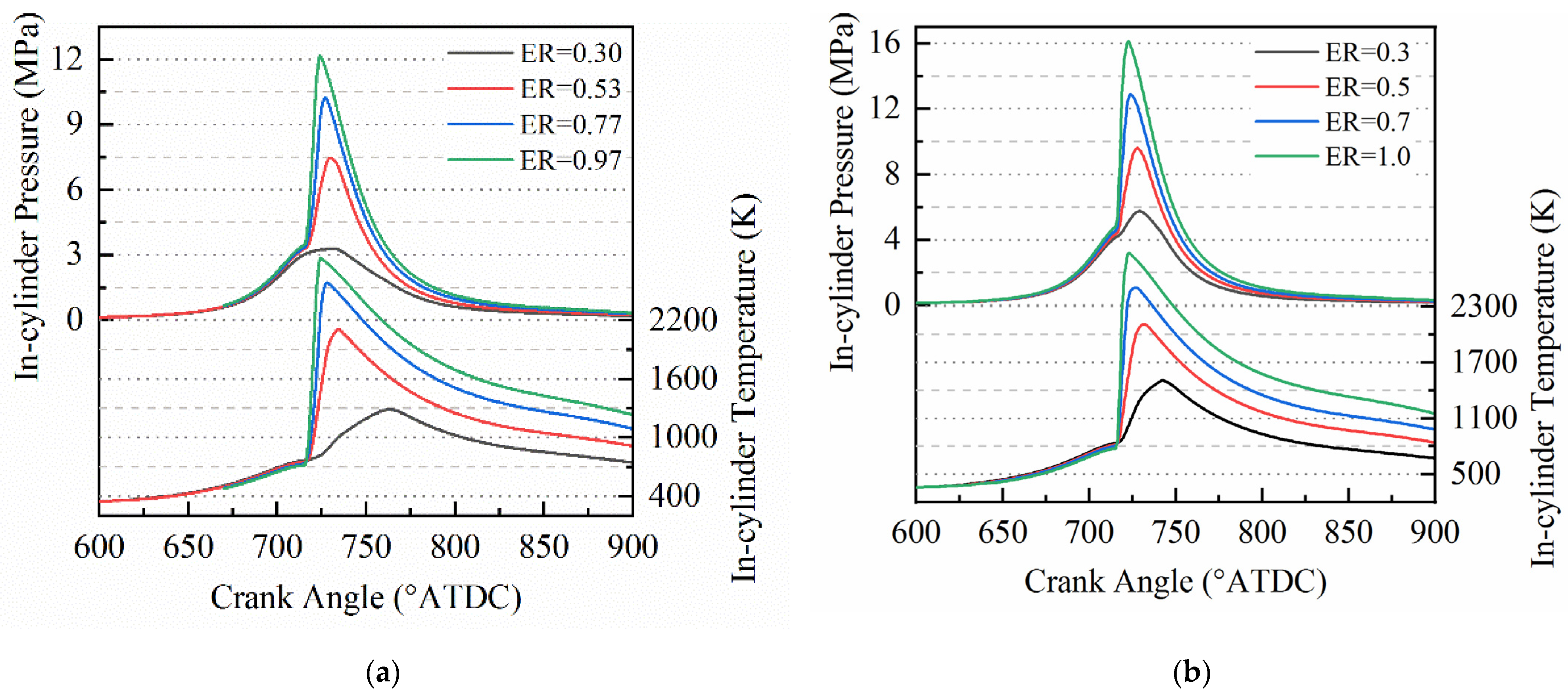
Figure 3 and Figure 4 respectively show the in-cylinder pressure, temperature, and heat-release rate curves for different equivalence ratios and compression ratios. It can be seen that the in-cylinder pressure, temperature, and heat-release rate increased with the increase of the equivalence ratio. Meanwhile, the combustion duration decreased significantly with the increase in the equivalence ratio. For the lean-burn condition with an equivalence ratio of 0.3, when the compression ratio increased from 12 to 15, the in-cylinder pressure, temperature, and heat-release rate were improved significantly. Especially for the peak pressure and peak heat-release rate, the increase was nearly double. Additionally, the single-cylinder power increased by more than 13%. Therefore, increasing the compression ratio can expand the lean flammability limit.
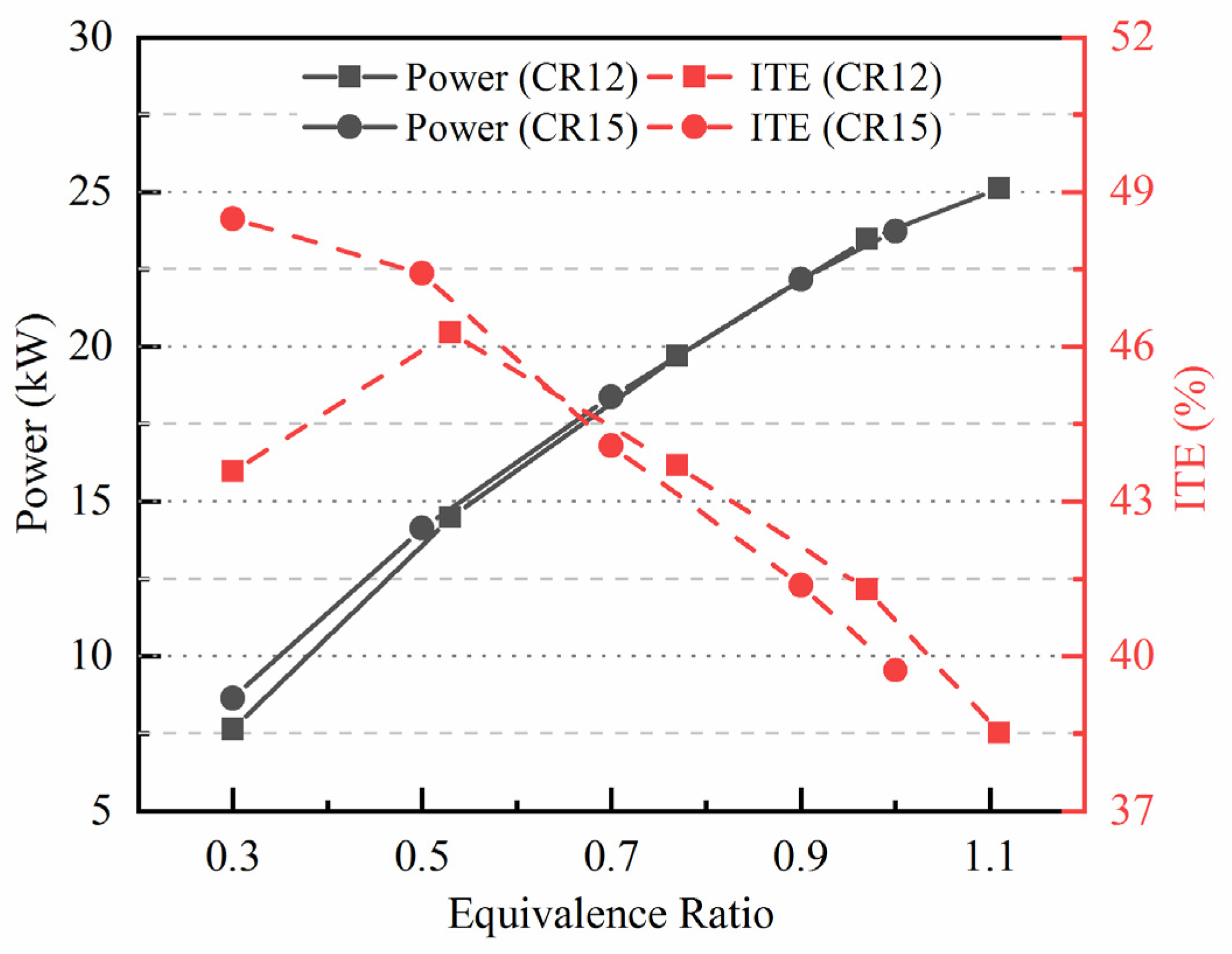
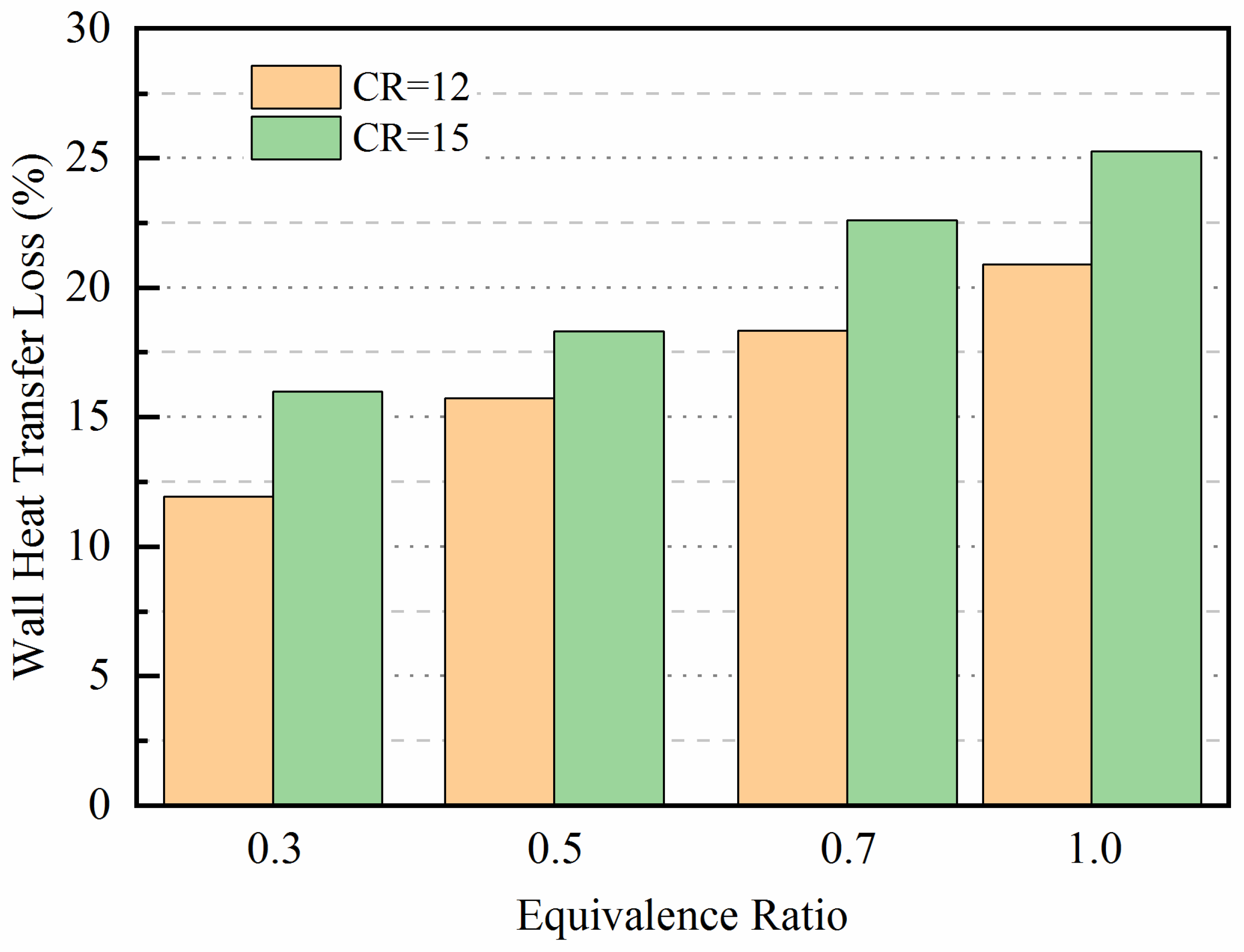
Keeping the intake air mass constant, increasing the equivalence ratio causes an increase in the hydrogen, so the corresponding power will also increase. As shown in Figure 5, when the equivalence ratio was higher than 0.5, the influence of the compression ratio on power was slight. In contrast, when the equivalence ratio was less than or equal to 0.5, increasing the compression ratio could significantly improve the power; when the equivalence ratio was 0.3, the power increased by more than 13% with the compression ratio increasing from 12 to 15. This is mainly because under the ultra-lean combustion condition, a higher compression ratio can increase the combustion rate, shorten the combustion duration, and then improve the peak pressure and thermal efficiency. With the increase in the equivalence ratio, the ITE gradually decreased, mainly due to the increase in the wall heat transfer loss caused by the gradual increase in the in-cylinder temperature. As shown in Figure 6, the proportion of the wall heat transfer loss respectively increased from about 12% and 16% under the equivalence ratio of 0.3 to about 21% and 25% under the equivalence ratio of 1.0 for a compression ratio of 12 and 15.
By studying the influence of equivalence ratio and ignition timing on combustion and performance, it was found that with the increase in equivalence ratio, the combustion rate gradually increased, but the growth rate gradually slowed down [47]. Especially when the equivalence ratio decreased, it was lower under a high compression ratio. The sensitivity of ignition delay and combustion duration to equivalence ratio was higher than that of ignition timing, and it decreased with the increase in equivalence ratio.
The NOx emission increased gradually with the rise of the equivalence ratio. The NOx emission was the highest when the equivalence ratio was 0.6~0.9. Additionally, it would decrease with the delay of the ignition timing. The knock intensity also increased rapidly with the increase in the equivalence ratio. When the equivalence ratio was above 0.6, the knock intensity exceeded 0.5 MPa. Additionally, knock intensity would further increase with the increase in the compression ratio. Therefore, for the direct-injection hydrogen engine, the operation condition with an equivalence ratio less than 0.5 can obtain high thermal efficiency, low emission, and low knock intensity.

5.2. Effects of Intake Pressure on Combustion and Performance

Hydrogen engines usually work under lean combustion conditions. In order to achieve a high torque, it is desirable to increase the intake pressure. Meanwhile, raising the intake pressure can also improve the distribution of hydrogen in the injection process, thus achieving the purpose of stratified combustion and reducing wall heat transfer loss. The influence of intake pressure on combustion was studied, and the specific calculation parameters are shown in Table 4 [47]. When studying the influence of the intake pressure on the combustion of hydrogen engines, two different cases were chosen. One involves increasing the intake pressure with a fixed equivalence ratio, as shown in case 1 in Table 4, and the other involves fixing the hydrogen-injection mass and increasing the intake pressure. Under the second case, the equivalence ratio decreases with the increase in the intake pressure, as shown in case 2 in Table 4.
The effect of intake pressure on combustion with constant equivalence ratio.
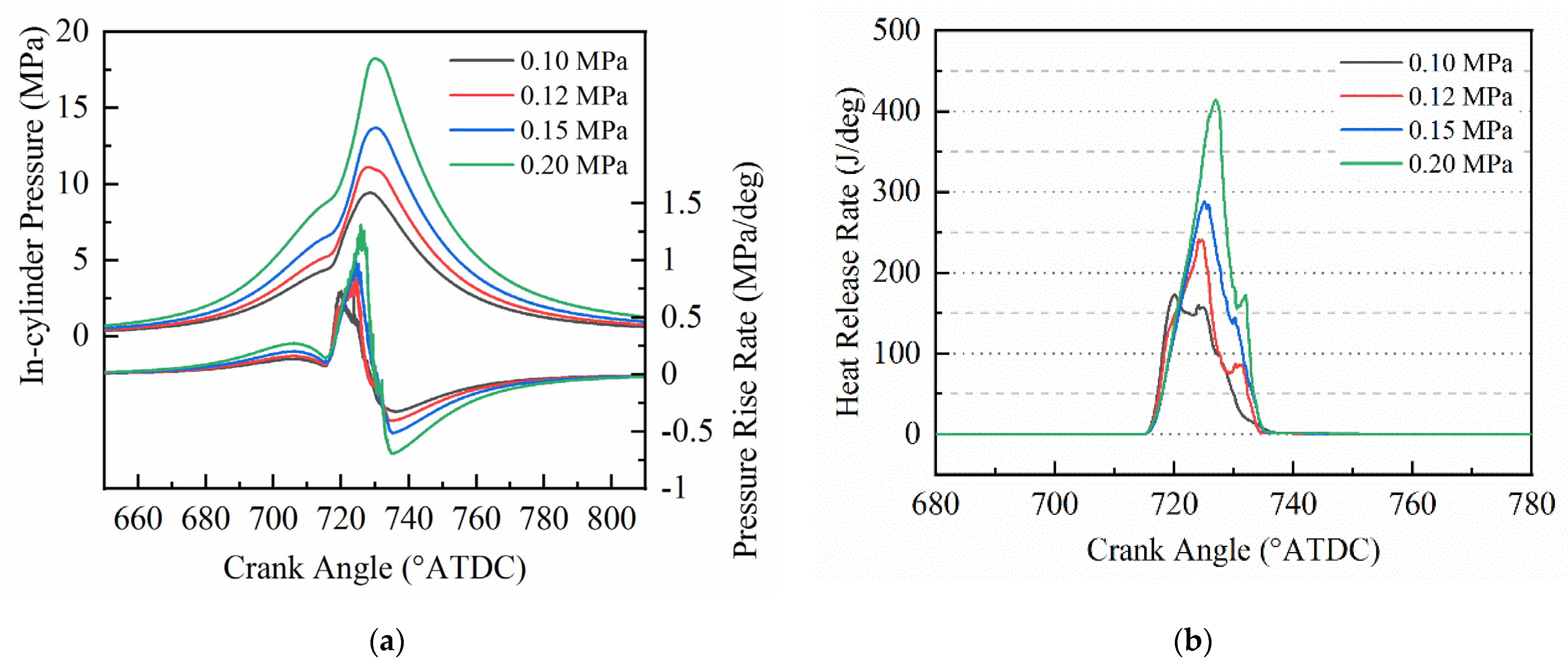
Figure 7 shows the in-cylinder pressure, pressure rise rate, and heat-release rate under different intake pressures when the fixed equivalence ratio was 0.5. It can be seen from the figure that the maximum heat-release rate and the pressure rise rate increased with the increase of intake pressure. With the intake pressure increasing from 0.1 MPa to 0.2 MPa, the maximum pressure rise rate increased from 0.73 MPa/deg to 1.31 MPa/deg, a nearly two-fold increase.
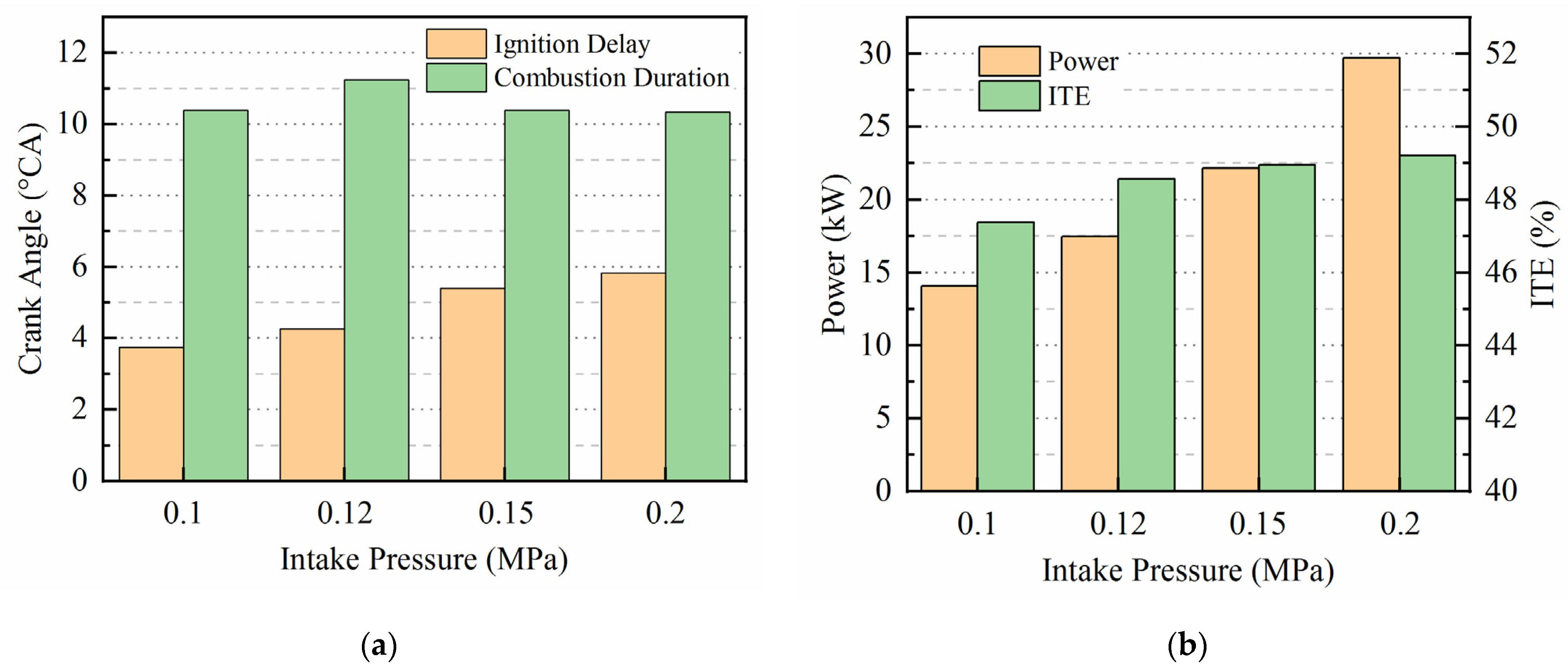
Figure 8 represents the ignition delay, the combustion duration, the indicated power, and the ITE under different intake pressures. As shown in Figure 8a, there was little difference in the combustion duration under different intake pressures. From the heat-release rate curve in Figure 7b, it can be seen that with the increase in intake pressure, the heat-release rate at the initial stage of combustion slightly decreased; therefore, the ignition delay increased. The main reason for this is that when the equivalence ratio was 0.5, the laminar flame speed decreased with the increase in pressure, so the development speed of the initial flame kernel slowed down. As shown in Figure 8b, the indicated power and the ITE became higher with the increase in the intake pressure. However, the growth rate of the ITE with the rise of the intake pressure gradually decreased, resulting from the negative compression work rising.
The effects of intake pressure on combustion with constant hydrogen-injection mass.
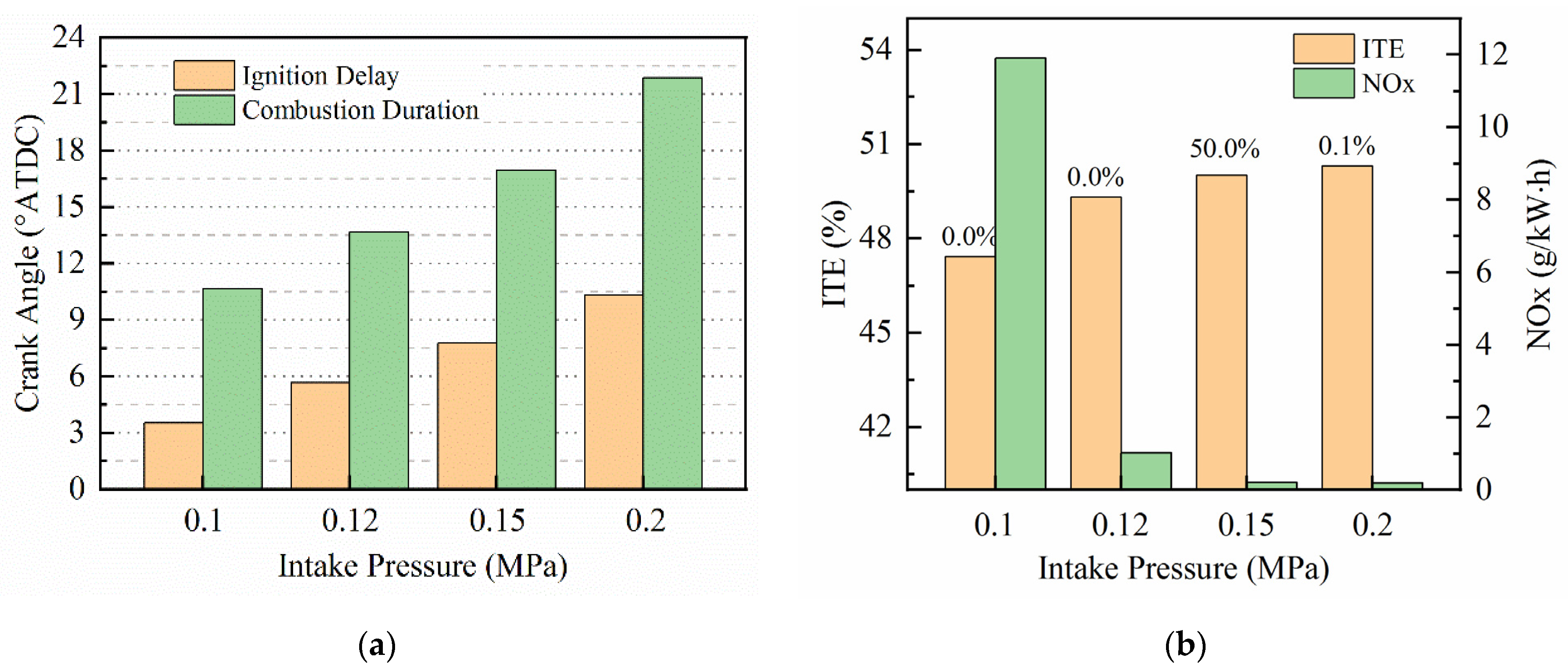
When the hydrogen-injection mass was constant, the equivalence ratio decreased with the increase in intake pressure. As shown in Figure 9, with the increase of intake pressure, although the in-cylinder pressure increased, the pressure rise rate decreased due to the reduction of the equivalence ratio, and the corresponding knock intensity also decreased; when the intake pressure was higher than 0.12 MPa, the knock intensity was lower than 0.1 MPa. Meanwhile, with the increase in intake pressure, the average in-cylinder temperature decreased. The heat-release rate changed little with the variation of the intake pressure under the combined effect of increasing intake pressure and decreasing equivalent ratio. Simultaneously, with the decrease of the equivalence ratio, both the ignition delay and combustion duration increased, as shown in Figure 10a. With the increase in intake pressure, the heat-transfer loss decreased due to the drop in the combustion temperature; therefore, the ITE increased, as shown in Figure 10b. At the same time, due to the decrease in combustion temperature, the NOx emission decreased significantly; when the intake pressure exceeded 0.15 MPa, the equivalence ratio was lower than 0.33, and the NOx emission was near zero.
In summary, with the increase of intake pressure, the indicated thermal efficiency, maximum heat-release rate, knock intensity, and maximum pressure rise rate increase when the equivalence ratio is constant. However, considering the increase in negative compression work, the growth rate of the indicated thermal efficiency gradually slowed down. When the hydrogen-injection mass was fixed, the equivalence ratio decreased with the increase of the intake pressure, and then the pressure rise rate and the combustion temperature decreased, which caused the ITE increase and the NOx emission to drop significantly. Therefore, when the load is constant, reducing the equivalence ratio by increasing the intake pressure can effectively improve thermal efficiency and reduce the NOx emission and knock intensity. Especially for the low and moderate loads, keeping the throttle wide open to reduce the pumping loss and adjusting the hydrogen-injection mass to meet different load demands is an effective control strategy to improve the thermal efficiency and reduce the emission [47].
Different from the non-turbocharging condition, the pre-ignition will occur frequently when the ignition timing is advanced under the turbocharging condition. Generally speaking, turbocharging is essential in improving engine output power. However, under the operation condition of low-speed heavy-duty engines, the load is likely to be limited by the ignition timing, while under light-duty conditions, power output is increased by turbocharging [18,19]. For hydrogen engines, turbochargers with larger turbine diameters are generally selected to obtain higher intake pressure and high exhaust mass flow during the full load operation so as to achieve high average effective pressure under more diluted hydrogen–air mixture operation conditions.

5.3. Effects of Exhaust Gas Recirculation on the Combustion and Performance of Hydrogen Engines

Exhaust gas recirculation (EGR), one of the most commonly used technologies to reduce NOx emissions, has been widely used in internal-combustion engines in recent years. Nande et al. studied the effect of external EGR on the performance of hydrogen engines and found that knock intensity and NOx emission can be reduced by using EGR [48]. However, with the increase of EGR rate, the combustion duration will increase.
In experimental research conducted by Taku Tsujimura et al. [21], in order to avoid any damage to the supercharger’s compressor caused by the condensation of water vapor existing in the exhaust gas of the hydrogen engine, nitrogen gas was used as EGR component. Diluting the fresh air with nitrogen reduces the intake oxygen concentration to 11.6 vol%, which is equivalent to an EGR rate of about 42%. The experimental results are different from the literature [48], and it was found that there were only small differences in the combustion duration, CA50, and other parameters. In addition, even if the ignition timing varied from 0° to −15° ATDC, the ITE and IMEP were almost unchanged regardless of the oxygen concentration. Only unburned hydrogen and NOx were affected by the EGR rate. With the decrease in the intake oxygen concentration, the NOx emission was significantly reduced.
The generation of NOx varies with the concentration of intake oxygen, while IMEP and ITE are not sensitive to the intake oxygen concentration. Although the heat-release increase at the beginning of combustion slightly decreased when the intake oxygen concentration was 11.6%, the heat-release process in other cases seemed similar. It can be surmised that the low-pressure EGR of the hydrogen engine almost included nitrogen and oxygen, so the in-cylinder temperature before the combustion on-set will not be affected by the intake oxygen concentration or EGR level. In addition, since the ignition energy of hydrogen is significantly lower than that of other fuels, the onset of combustion is hardly affected by the EGR rate.
Another measure to reduce NOx emissions is to spray water into the intake manifold or the cylinder [49]. Water injection is simultaneously used to reduce the knock tendency and improve ITE at stoichiometric ratio operation. Compared with gasoline, the higher laminar flame speed of hydrogen and the increase in fuel–energy ratio during the expansion operation offer the potential to improve the thermal efficiency of hydrogen engines [50]. The reduction in ignition delay and the acceleration of the combustion rate result in an early end to combustion. Compared with gasoline, an increased water content of the exhaust gas, and therefore a higher heat capacity, results in a decreased exhaust gas temperature [51]. In addition, the high burning velocity and wide ignition limits of hydrogen enable a high charge dilution either by external exhaust gas recirculation or by increasing the relative air–fuel ratio [52]. Further, the combination of both measures can also be of interest since they can achieve equivalent NOx reduction at ultra-lean or high EGR operation [25]. However, high dilution requires a boost system to provide enough intake pressure under all operating conditions.
Increasing the intake pressure can further lower the combustion temperature, which leads to a reduction of the NOx emissions and can achieve near-zero raw emission engine operation [53]. Marcus, F. et al. demonstrated the dependency of the indicated efficiency, the center of combustion, the NOx emissions, and the boost pressure on the brake mean effective pressure and the relative air–fuel ratio. The lean operation range was limited towards higher brake mean effective pressures and higher relative air–fuel ratios. The increase of the air–fuel can increase the exhaust gas flow, but significantly reduces the exhaust gas temperature and thus reduces the available enthalpy of the exhaust gas that can be used for boost pressure generation. Hence, when the excess air coefficient is 2.5, only under low load with BMEP below 0.8 MPa, the NOx emission is less than 10 ppm. For the working condition of a brake mean effective pressure of 0.4 MPa, the excess air coefficient equal to 1.5 is enough to make the original NOx emission less than 10 ppm. Therefore, near-zero NOx emissions can be realized by lean combustion only under low-load conditions. However, lean combustion under moderate and high loads has no obvious advantage compared with EGR stoichiometric combustion, especially in NOx emissions.
Although NOx emissions can be significantly reduced through lean combustion and EGR technology at low and medium loads, in most cases, appropriate aftertreatment techniques are still needed for achieving near-zero emissions. For lean combustion, NOx emission can be reduced by selective catalytic reduction (SCR) of urea or NOx storage catalysts (NSC) [54]. Another option for lean exhaust gas after treatment is through hydrogen-selective catalysis, which is an interesting option because no additional tank containing a reducing agent is required [55,56]. Using a three-way catalyst (TWC) can fully reduce the content of NOx in stoichiometric ratio operation. Therefore, the solution of engine exhaust gas after treatment is feasible, but it may increase the complexity of the system.

6. Knock of Hydrogen Internal-Combustion Engines

6.1. Knock Characteristics and Influence Factors of Hydrogen Internal-Combustion Engines

Theoretically, hydrogen has good knock resistance because of the higher octane number. Zhao et al. [57] studied the effect of octane number on knock combustion and found that increasing the octane number under certain conditions could indeed reduce the reactivity of the end mixture. However, with the increase in the ignition timing, the sensitivity of the octane number to the end mixture activity was gradually decreased. Therefore, it is insufficient to describe the fuel’s knock resistance by only considering octane numbers. For gaseous fuels, methane numbers are commonly used to evaluate their knock resistance [58,59,60]. The methane number of hydrogen fuel is 0, which means that hydrogen is extremely prone to knocking; for this reason, Karim and his team have conducted a series of hydrogen combustion tests on a CFR (Cooperative Fuel Research) engine. Their results showed that the knock was observed at compression ratios in the range of 6 to 14 [61,62]; in the case of high equivalence ratios and high compression ratios, the knock was more severe.
However, due to the rapid propagation speed of hydrogen flame, not all knocks are caused by the auto-ignition of the end mixture; the mild knocks are caused by unstable combustion, and the severe knocks result from the end mixture’s auto-ignition [63]. In addition, the interaction of the pressure wave and the flame can also cause severe knocking [64]. In the study of Ye et al. [65], it was found that the mixture’s uniformity had an important effect on the knock and the unburned end mixture mass at the moment of auto-ignition was directly related to the knock intensity.
The knocking in the spark-ignition mode is mainly caused by the end mixture’s random auto-ignition [66]; the generated pressure wave due to the auto-ignition flame is reflected back and forth in the cylinder, resulting in the production of noise and the destruction of the engine. In the compression-ignition mode, the rough operation is mainly related to the combustion rate [67]. The multipoint auto-ignition leads to an excessive pressure-rise rate, which causes a huge impact on some components such as the piston and cylinder head. The simulation research on the hydrogen engine knock found that the rough operation occurred similarly to that of a diesel engine when increasing the equivalence ratio to a certain level and achieving a high combustion rate [47]. Under these research conditions, the end mixture does not experience auto-ignition, but the caused significant pressure fluctuation and produced pressure wave could further promote the combustion faster due to the rapid combustion and rapid pressure increase. Antunes et al. [68] compared the combustion characteristics of the compression ignition engine for hydrogen and that for diesel; the results obtained exhibited that the hydrogen engine was more likely to work roughly due to a faster burning rate [69]. On the other hand, due to the high auto-ignition temperature of hydrogen, the mixture can auto-ignite until the intake gas temperature is heated to about 120 °C, which greatly reduces the intake efficiency.
Xu et al. [70] studied the effect of auto-ignition position on the hydrogen engine knock intensity. As with gasoline engines, the auto-ignition position directly affects the thermodynamic state of the end mixture, thereby affecting the knock intensity. To macroscopically understand the knocking influence of different parameters and the corresponding knock boundary, Xue et al. [71] established a two-dimensional hydrogen engine model, and found that the compression ratio and intake air temperature both had a more significant impact on knock than that of the equivalent ratio and the ignition timing. As the compression ratio increased, the knock operation area gradually widened and the non-knock operation area gradually narrowed, which means the normal operating range became narrower for the high-compression-ratio engine.
The luminescence of the combustion product infers pressure oscillation. Based on the spectral amplitude at the corresponding resonance frequency, realizing the visualization of the pressure oscillation mode can contribute to a more intuitive understanding of the different models of the pressure wave during knock [72]. Luo et al. [73] compared the different modes’ resonance frequencies of hydrogen and gasoline. They found that the frequency of hydrogen engine each mode is higher than that of gasoline engine; thus, the frequency range of knock detection should be appropriately adjusted for hydrogen internal-combustion engines.

6.2. The Natural Mechanism of the Knock Formation of the Hydrogen Internal-Combustion Engines

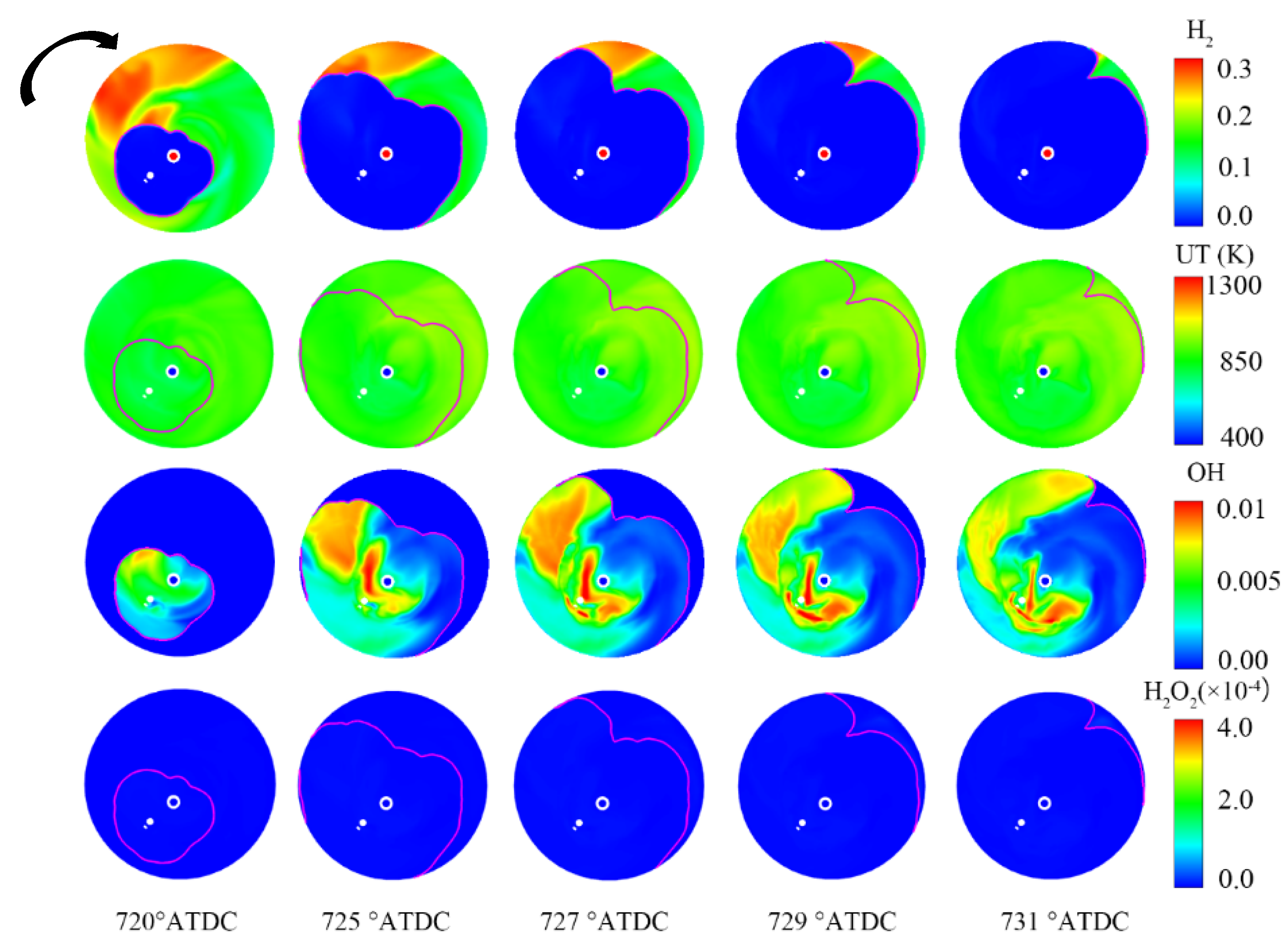
To study the natural mechanism of knocking in hydrogen internal-combustion engines, it is necessary to analyze the intermediate products of combustion reaction, the flame propagation, the thermodynamic state of the end mixture, and the generation and development of pressure waves. Moreover, the flame-propagation process of normal combustion should also be analyzed for a better understanding of the knock characteristics of hydrogen internal-combustion engines [47]. Figure 11 shows the flame-propagation and change processes under normal combustion. The solid purple line in the figure is the contour line of G = 0, representing the position of the flame front. From the distribution of hydrogen, it can be seen that there was a rich region in the upper left where the flame-propagation speed was significantly accelerated along the clockwise direction, as shown by the black arrow in Figure 11. Correspondingly, the concentration of OH was significantly increased, which indicates that OH is an important intermediate product of hydrogen chain reactions and has an important effect on flame propagation. In addition, the flame propagation speed was relatively slow during normal combustion, and the overall heat-release rate was low; therefore, there was no obvious increase in the unburned mixture temperature (UT). The H2O2 concentration was too low to be visible in Figure 11.
The research on the natural mechanism of knock formation for hydrogen engines was conducted through increasing the intake gas temperature and changing the thermodynamic state of the end mixture for reaching the auto-ignition condition [47]. Figure 12 shows the main flame propagation process, pressure waves, and the change of intermediate species during knocking. It can be seen that before 722.8° ATDC, the main flame spread around from the spark plug. However, the unburned temperature was significantly increased, and a large amount of H2O2 was generated in the unburned region of the front of main flame during flame propagation. From the reaction path and sensitivity analysis, it was found that there was no competition with the main chain reactions of H radical in the unburned mixture, the reaction rate of reaction (1) was increased, and the HO2 concentration was increased when increasing the temperature and pressure of the unburned mixture. Then, the concentration of H2O2 was also increased, as the reaction (2) accelerates due to the increase in HO2 concentration; therefore, the variations of HO2 and H2O2 in the unburned mixture are consistent. With the concentrations of HO2 and H2O2 rising, the production rate of OH was increased as reactions (3) and (4) show. Therefore, HO2 and H2O2 are consumed at 722.8° ATDC, meanwhile generating a large amount of OH. At the same time, the temperature and pressure were increased significantly. As can be seen from the distribution of the pressure difference, the pressure wave and the main flame were coupled. When promoting the pressure waves, the propagation speed of the auto-ignition combustion flame was significantly increased and greater than that of the main flame, leading to a higher second peak of the heat-release rate. In addition, from the distribution of OH, it can be seen that in the burned region, the OH concentration near the pressure wave front was also significantly remarkable, which means the pressure wave promoted exothermic reactions in the burned area.
H + O 2 + M HO 2 + M
HO 2 + HO 2 H 2 O 2 + O 2
HO 2 + H OH + OH
H 2 O 2 + O OH + HO 2

6.3. Knock Control Strategy of Hydrogen Internal-Combustion Engines

Among the common methods of suppressing knocking include increasing the turbulence kinetic energy [74], optimizing the combustion chamber structure and spark plug position [75], reducing the compression ratio or end mixture temperature, adding anti-knock additives, and spraying water [76]. These methods can also be applied to hydrogen engines.
Ignition timing and spark plug location both have a significant effect on the knock. An appropriate ignition delay can effectively reduce the knock intensity. Owing to the onset of knock (the rapid spontaneous ignition of a fraction of the in-cylinder fuel–air mixture during the latter part of combustion) depends on the mixture temperature and pressure inside the engine cylinder; delaying ignition timing can decrease both of these variables [77], and the knock intensity can be controlled by controlling the ignition timing. When the ignition is delayed, correspondingly, the remaining unburned mixture mass is reduced, and the knock intensity decreases.
The flame-propagation speed of hydrogen is directly related to the equivalence ratio [78], and the combustion speed under ultra-lean equivalence ratio is even lower than that of gasoline. Moreover, the relationship of octane number of hydrogen and the equivalence ratio is also a function. The effective octane number can achieve about 140 when the equivalence ratio is 0.4. Salvi et al. [79] studied the effects of compression ratio, ignition timing, and EGR rate on combustion and emission for a hydrogen port-injection engine. It was found that increasing the compression ratio could improve thermal efficiency and lead to an increase in NOX and knock intensity, while delaying ignition and increasing the EGR rate could effectively alleviate knock and reduce NOX. This is because H2O is the main reaction product of hydrogen, the main components of EGR are H2O and N2 while most of the water vapor in exhaust gas will be condensed, and the main component for cold EGR is N2. In order to compare the effects of cold and hot EGR, Duan [80] compared the influences of the H2O/N2 and N2 dilution method for hydrogen combustion; it was found that both the dilution components could effectively reduce the laminar flame velocity and decrease the burned gas temperature; the effect of H2O/N2 was especially better. Shrestha et al. [81] conducted a similar study and found that diluents (N2 and CO2) could expand the knock limits of gaseous fuels. Moreover, CO2 has a higher specific heat capacity, which is more effective in reducing the combustion temperature and suppressing knock.
A more direct way to relief knock is spraying water into the cylinder due to the water evaporation, reducing the in-cylinder temperature and diluting the mixture [82,83,84], thereby alleviating knocking and lowering NOx. Furthermore, the water injection timing and the amount have a direct impact on the knock mitigation [52,85]. In addition to spraying water into the cylinder, it is also effective to spray water into the intake port or manifold, and, correspondingly, the intake efficiency could be reduced [86]. Although injection water can suppress knock and reduce NOX, the complexity of the whole system will also be increased; meanwhile, the water will also cause lubricating oil emulsion.

7. Conclusions

In summary, both the influence factors of combustion and hydrogen internal-combustion engines’ performance are very complicated. The design of the combustion system and hydrogen injector matching, hydrogen-injection pressure and hydrogen-injection strategy, inlet pressure, compression ratio, and EGR are among the key factors affecting hydrogen combustion and hydrogen internal-combustion engines’ performance. Coordinating control of these parameters is important to ensure a higher efficiency and lower emission for the hydrogen engine. In addition, the knock formation conditions and influencing factors of hydrogen internal-combustion engines are much different from those of other traditional fuel engines. The knock formation mechanism of hydrogen internal-combustion engines needs further exploration and research. The main conclusions are as follows:
Compared with gasoline engines, both port-injection and direct-injection hydrogen engines have good effective thermal efficiency. However, direct-injection hydrogen internal-combustion engines have more advantages in terms of power performance, fuel economy, and NOx emission, which is an ideal hydrogen supply method. For direct-injection hydrogen engines, the late injection strategies should be further adapted to achieve to an ideal constant volume degree and lower efficiency loss reduction such as compression work and heat transfer to coolant.
The structure and arrangement of the injector for hydrogen internal-combustion engines have a great influence on the formation of the mixture. For port injection, with the increase of the distance between the nozzle and the intake valve, the optimal range of hydrogen-injection timing becomes narrower, and the optimal injection timing is advanced. There exists an optimal nozzle-hole diameter to minimize the amount of residual hydrogen in the intake port. For direct injection, the structure and arrangement of the injector directly affects the hydrogen flow and distribution of hydrogen in the combustion chamber, and also affects the combustion performance. Outward-opening nozzles have a larger flow rate, which can meet the requirements of heavy load conditions, and the penetration distance of the hole-injector is longer, which is conducive to the diffusion of hydrogen. Single-hole injectors have large jet flow and a tumble-like vortex motion can be formed to speed up the mixing rate. For multi-hole injectors, the jets will collapse and merge together, and the dominant mechanism of the mixing process is the effect of hydrogen jets and cylinder wall. A small nozzle diameter can reduce the surface area of the jet, thereby increasing the air entrained by the jet, making the hydrogen mixture more uniform. With the increase in the nozzle diameter, the hydrogen concentration gradient at the top of the hydrogen jet becomes smooth, which benefits ignition.
The equivalent ratio significantly influences the combustion and performance of hydrogen internal-combustion engines. With the increase in the equivalent ratio, the combustion rate increases, but when the equivalent ratio increases up to a certain degree, the increase rate of combustion speed slows; when the equivalent ratio is greater than 0.7, the sensitivity of the combustion rate to the equivalent ratio becomes low, and the sensitivity to the equivalent ratio is lower at higher compression ratios. In addition, for the ultra-lean burn condition (such as the equivalent ratio being 0.3), the increase of the compression ratio can significantly improve the indicated power and thermal efficiency. Therefore, increasing the compression ratio can further expand the limit of lean burn. The sensitivities of the ignition delay period and combustion duration to the equivalent ratio are both greater than that of the ignition timing.
Lean burn of hydrogen engines requires a higher boost pressure to maintain a sufficiently low equivalent ratio; otherwise, lean burn engine operation will result in insufficient torque or power, which is lower than the level obtained by stoichiometric gasoline engine operation. On the other hand, when a supercharged stoichiometric mixture with EGR is selected, a 30% higher power output than gasoline can be achieved, but a catalytic post-treatment system for NOX removal is also required.
NOx emission is strongly correlated with the global equivalent ratio in the absence of EGR. Near-zero NOx emissions can be realized by lean combustion only under low load conditions. However, lean combustion under moderate and high loads has no obvious advantage compared to EGR stoichiometric combustion, especially in NOx emissions.
When nitrogen is used to simulate EGR, the EGR rate only slightly affects combustion performance. No matter how significant the EGR rate is, the indicated thermal efficiency, average indicated pressure, and CA50 are not much different. However, increasing the EGR rate can significantly reduce nitrogen oxide emissions. On the contrary, when water is used as an EGR medium, the combustion rate and combustion phase will change significantly with the increase of the EGR rate.
Compared with gasoline engines, the indicated efficiency of hydrogen engines operating at stoichiometric ratios is decreased. Intake dilution (lean burning) shows great potential in the indicated efficiency improvement. Exhaust post-treatment and purification can achieve near-zero engine emissions during operation.
The compression ratio and intake air temperature both have a more significant impact on the knock than that of the equivalent ratio and the ignition timing. With the increase of the compression ratio, the knock operation range gradually widens, which means that the normal operating range of the high-compression-ratio engine becomes narrower.
Knock formation mechanism research found that before spontaneous combustion, the flame propagation process is similar to that of the normal combustion, except the unburned mixture at the end, which itself has a high temperature, accelerates the low-temperature reaction rate and accumulates a large amount of HO2 and H2O2. The increased concentration of HO2 and H2O2 further accelerates the formation of OH. When OH reaches a certain concentration, the main chain reactions are induced, which means the occurrence of spontaneous combustion. Owing to the large amount of HO2 and H2O2 generated by low-temperature reactions in the unburned zone, the combustion rate and flame propagation speed have been greatly increased. The faster combustion rate will release more heat, thus further increasing the energy of the pressure wave. The enhanced pressure wave promotes the primary chain reaction and increases the combustion rate and the flame-propagation speed. The coupling and promotion of pressure wave and spontaneous combustion flame both significantly increase the propagation speed of the spontaneous combustion flame and the amplitude of pressure wave, ultimately leading to severe knock.
Some measures such as the lean burn, ignition or injection delay, EGR, or spraying water into the cylinder could effectively alleviate knock.
Although hydrogen internal-combustion engines have made significant progress recently, there are many topics which require further investigation in the future. For example, a more suitable and accurate combustion model for hydrogen needs to be developed for CFD simulation research. In order to guide the development of hydrogen internal-combustion engines, among the combustion chamber and hydrogen-injection system design, supercharger match and combustion strategy optimization still need to be systematically carried out. The formation mechanism and evaluation method of knocking also need further research so that knocking can be effectively controlled.

Author Contributions

Conceptualization, W.G.; methodology, Z.F. and W.G.; software, Z.F. and Y.L. (Yong Li); validation, Y.L. (Yong Li) and W.G.; formal analysis, Z.F., Y.L. (Yong Li) and W.G.; investigation, Y.L. (Yong Li), W.G. and Z.F.; resources, Z.F., Y.L. (Yong Li) and Y.L. (Yuhuai Li); data curation, Y.L. (Yuhuai Li), Y.L. (Yong Li) and J.Z.; writing—original draft preparation, W.G., Z.F. and Y.L. (Yong Li); writing—review and editing, Z.F., W.G. and J.Z.; visualization, W.G.; supervision, W.G. and Y.L. (Yuhuai Li); project administration, W.G. All authors have read and agreed to the published version of the manuscript.

Funding

This research received no external funding.

Institutional Review Board Statement

Not applicable.

Informed Consent Statement

Not applicable.

Data Availability Statement

We choose exclude this statement if the study did not report any data.

Conflicts of Interest

The authors declare no conflict of interest.

Nomenclature

ITEIndicated Thermal Efficiency
BTEBrake Thermal Efficiency
IMEPIndicated Mean Effective Pressure
CA10Crank Angle When Cumulative Heat Release Reaches 10%
CA50Crank Angle When Cumulative Heat Release Reaches 50%
CA90Crank Angle When Cumulative Heat Release Reaches 90%
ppmPart Per Million
SOIStart of Injection
ATDCAfter Top Dead Center
BTDCBefore Top Dead Center
EGRExhaust Gas Recirculation

References

  1. Hydrogen Energy: New Race Track for World Energy Pattern. Shenzhen Special Zone Daily, 1 December 2021.
  2. Chen, H.C.; Pei, P.C. A study on the economical lifetime of the proton exchange membrane fuel cells for vehicles. Automot. Eng. 2015, 37, 998–1004. [Google Scholar]
  3. Verhelst, S.; Wallner, T. Hydrogen-fueled internal combustion engines. Prog. Energy Combust. Sci. 2009, 35, 490–527. [Google Scholar] [CrossRef] [Green Version]
  4. Chitragar, P.R.; Shivaprasad, K.V.; Nayak, V.; Bedar, P.; Kumar, G.N. An experimental study on combustion and emission analysis of four cylinder 4-stroke gasoline engine using pure hydrogen and LPG at idle condition. Energy Procedia 2016, 90, 525–534. [Google Scholar] [CrossRef]
  5. Das, L.M. Hydrogen-fueled internal combustion engines. Compend. Hydrog. Energy 2016, 3, 177–217. [Google Scholar]
  6. Liu, F.S.; Hao, L.J.; Heitz, P.B. Technical status quo and development prospect of hydrogen IC engine. Automot. Eng. 2006, 28, 621–625. [Google Scholar]
  7. Mazloomi, K.; Gomes, C. Hydrogen as an energy carrier: Prospects and challenges. Renew. Sustain. Energy Rev. 2012, 16, 3024–3033. [Google Scholar] [CrossRef]
  8. Sun, B.; Bao, L.; Luo, Q. Development and trends of direct injection hydrogen internal combustion engine technology. Automot. Saf. Energy 2021, 12, 265–278. [Google Scholar]
  9. Sun, N.; Ma, F.H. Developing situation and direction of hydrogen internal combustion engine. Veh. Engine 2006, 2, 1–5. [Google Scholar]
  10. Li, X.R.; Wei, R.; Sun, B.G. Combustion Science and Technology of Internal Combustion Engine; Beijing University of Aeronautics and Astronautics Press: Beijing, China, 2012. [Google Scholar]
  11. Mathur, H.B.; Das, L.M. Performance characteristics of a hydrogen fuelled S.I. engine using timed manifold injection. Int. J. Hydrog. Energy 1991, 16, 115–127. [Google Scholar] [CrossRef]
  12. Rana, K.K.; Natarajan, S.; Jilakara, S. Potential of hydrogen fuelled IC engine to achieve the future performance and emission norms. SAE 2015, No. 2015-26-0050. [Google Scholar] [CrossRef]
  13. Berckmϋller, M.; Rottengruber, H.; Eder, A.; Brehm, N.; Elsässer, G.; Müller-Alander, G.; Schwarz, C. Potential of a charged SI-hydrogen engine. SAE 2003, No. 2003-01-3210. [Google Scholar] [CrossRef]
  14. Rottengruber, H.; Berckmϋller, M.; Elsässer, G.; Brehm, N.; Schwarz, C. Direct-injection hydrogen SI-engine operation strategy and power density potentials. SAE 2004, 113, 1749–1761. [Google Scholar]
  15. Thomas, W.; Hennning, L.B.; Stephen, G.; Mike, D.; Wolfgang, T.; Dieter, M.; Thomas, K. Fuel economy and emissions evaluation of BMW hydrogen 7 mono-fuel demonstration vehicles. Int. J. Hydrog. Energy 2008, 33, 7607–7618. [Google Scholar]
  16. Szwabowski, S.J.; Hashemi, S.; Stockhausen, W.F.; Natkin, R.J.; Reams, L.; Kabat, D.M.; Potts, C. Ford hydrogen engine powered P2000 vehicle. SAE 2002, No. 2002-01-0243. [Google Scholar] [CrossRef]
  17. Tang, X.; Kabat, D.M.; Natkin, R.J. Ford P2000 hydrogen engine dynamometer development. SAE 2002, 111, 631–642. [Google Scholar]
  18. Wallner, T.; Scarcelli, R.; Nande, A.M.; Naber, J.D. Assessment of multiple injection strategies in a direct-injection hydrogen research engine. SAE 2009, 2, 1701–1709. [Google Scholar] [CrossRef]
  19. Nicholas, S.M.; Thomas, W.; Riccardo, S. A hydrogen direct injection engine concept that exceeds U.S. DOE light-duty efficiency targets. SAE 2012, 5, 838–849. [Google Scholar]
  20. Kawamura, A.; Sato, Y.; Naganuma, K.; Yamane, K.; Takagi, Y. Development project of a multi-cylinder DISI hydrogen ICE system for heavy duty vehicles. SAE 2010, No. 2010-01-2175. [Google Scholar] [CrossRef]
  21. Taku, T.; Yasumasa, S. Development of a large-sized direct injection hydrogen engine for a stationary power generator. Int. J. Hydrog. Energy 2019, 44, 11355–11369. [Google Scholar]
  22. Verhelst, S.; Maesschalck, P.; Rombaut, N.; Sierens, R. Increasing the power output of hydrogen internal combustion engines by means of supercharging and exhaust gas recirculation. Int. J. Hydrog. Energy 2009, 34, 4406–4412. [Google Scholar] [CrossRef]
  23. Verhelst, S.; Demuynck, J.; Martin, S.; Vermeir, M.; Sierens, R. Investigation of supercharging strategies for PFI hydrogen engines. In Proceedings of the SAE 2010 World Congress, Detroit, MI, USA, 13–15 April 2010. No. 2010-01-0582. [Google Scholar]
  24. Shiro, T.; Yasushi, I.; Ryo, M.; Mikio, N. High-efficiency and low-NOx hydrogen combustion by high pressure direct injection. SAE 2010, 3, 259–268. [Google Scholar]
  25. Unni, J.K.; Bhatia, D.; Dutta, V.; Mohan Das, L.; Jilakara, S.; Subash, G.P. Development of hydrogen fueled low NOx engine with exhaust gas recirculation and exhaust after treatment. SAE 2017, 10, 46–54. [Google Scholar]
  26. Mohammadi, A.; Shioji, M.; Nakai, Y.; Ishikura, W.; Tabo, E. Performance and combustion characteristics of a direct injection SI hydrogen engine. Int. J. Hydrog. Energy 2007, 32, 296–304. [Google Scholar] [CrossRef]
  27. Zhang, C.; Sun, B.G.; Wang, X.; Bao, L.; Chai, H. Direct-Injection Hydrogen Jet Characteristics of Outward-Opening Nozzle. Veh. Engine 2020, 7–12, 24. [Google Scholar]
  28. Hamada, K.I.; Rahman, M.M.; Abdullah, M.A.; Bakar, B.A.; Aziz, R.A. Effect of mixture strength and injection timing on combustion characteristics of a direct injection hydrogen-fueled engine. Int. J. Hydrog. Energy 2013, 38, 3793–3801. [Google Scholar] [CrossRef]
  29. Yip, H.L.; Srna, A.; Yuen, A.C.Y.; Kook, S.; Taylor, R.A.; Yeoh, G.H.; Medwell, P.R.; Chan, Q.N. A review of hydrogen direct injection for internal combustion engines: Towards carbon-free combustion. Appl. Sci. 2019, 9, 4842. [Google Scholar] [CrossRef] [Green Version]
  30. Takagi, Y.; Mihara, Y.; Konagaya, R.; Takagi, Y.; Mihara, Y. Unsteady three-dimensional computations of the penetration length and mixing process of various single high-speed gas jets for engines. SAE 2017, No. 2017-01-0817. [Google Scholar] [CrossRef]
  31. Wallner, T.; Ciatti, S.; Bihari, B. Investigation of injection parameters in a hydrogen di engine using an endoscopic access to the combustion chamber. SAE 2007, No. 2007-01-1464. [Google Scholar] [CrossRef]
  32. Wang, L.; Yang, Z.; Huang, Y.; Huang, Y.; Liu, D.; Duan, J.; Guo, S.; Qin, Z. The effect of hydrogen injection parameters on the quality of hydrogen–air mixture formation for a PFI hydrogen internal combustion engine. Int. J. Hydrog. Energy 2017, 42, 23832–23845. [Google Scholar] [CrossRef]
  33. Wallner, T.; Nande, A.M.; Naber, J. Evaluation of injector location and nozzle design in a direct-injection hydrogen research engine. In Proceedings of the 2008 SAE International Powertrains, Fuels and Lubricants Congress, Shanghai, China, 23–25 June 2008. No. 2008-01-1785. [Google Scholar]
  34. Eichlseder, H.; Wallner, T.; Freymann, R.; Ringler, J. The potential of hydrogen internal combustion engines in a future mobility scenario. SAE 2003, No. 2003-01-2267. [Google Scholar] [CrossRef]
  35. Salazar, V.M.; Kaiser, S.A. An optical study of mixture preparation in a hydrogen-fueled engine with direct injection using different nozzle designs. SAE 2009, 2, 119–131. [Google Scholar] [CrossRef]
  36. Takagi, Y.; Oikawa, M.; Sato, R.; Kojiya, Y.; Mihara, Y. Near-zero emissions with high thermal efficiency realized by optimizing jet plume location relative to combustion chamber wall, jet geometry and injection timing in a direct-injection hydrogen engine. Int. J. Hydrog. Energy 2019, 44, 9456–9465. [Google Scholar] [CrossRef]
  37. Koyanagi, K.; Hiruma, M.; Yamane, K.; Furuhama, S. Effect of hydrogen jet on mixture formation in a high-pressure injection hydrogen fueled engine with spark ignition. SAE 1993, No. 931811. [Google Scholar] [CrossRef]
  38. Sukumaran, S.; Kong, S. Numerical study on mixture formation characteristics in a direct-injection hydrogen engine. Int. J. Hydrog. Energy 2010, 35, 7991–8007. [Google Scholar] [CrossRef] [Green Version]
  39. Verhelst, S.; Demuynck, J.; Sierens, R.; Scarcelli, R.; Matthias, N.S.; Wallner, T. Update on the progress of hydrogen-fueld internal combustion engines. In Renewable Hydrogen Technologies; Elsevier: Amsterdam, The Netherlands, 2013; pp. 381–400. [Google Scholar]
  40. Yang, J.; Ji, C.; Wang, S.; Wang, D.; Shi, C.; Ma, Z.; Zhang, B. Numerical study of hydrogen direct injection strategy on mixture formation and combustion process in a partially premixed gasoline Wankel rotary engine. Energy Convers. Manag. 2018, 176, 184–193. [Google Scholar] [CrossRef]
  41. Fan, B.; Zhang, Y.; Pan, J.; Liu, Y.; Chen, W.; Otchere, P.; Wei, A.; He, R. The influence of hydrogen injection strategy on mixture formation and combustion process in a port injection (PI) rotary engine fueled with natural gas/hydrogen blends. Energy Convers. Manag. 2018, 173, 527–538. [Google Scholar] [CrossRef]
  42. Kaiser, S.; White, C.M. PIV and PLIF to evaluate mixture formation in a direct-injection hydrogen-fuelled engine. SAE 2008, 1, 657–668. [Google Scholar] [CrossRef]
  43. Wimmer, A.; Wallner, T.; Ringler, J.; Gerbig, F. H2-direct injection—A highly promising combustion concept. SAE 2005, No. 2005-01-0108. [Google Scholar] [CrossRef]
  44. Messner, D.; Wimmer, A.; Udo, G.; Gerbig, F. Application and validation of the 3D CFD method for a hydrogen fueled IC engine with internal mixture formation. SAE 2006, No. 2006-01-0448. [Google Scholar] [CrossRef]
  45. White, C.M. A qualitative evaluation of mixture formation in a direct-injection hydrogen-fuelled engine. SAE 2007, No. 2007-01-1467. [Google Scholar] [CrossRef]
  46. Keskinen, K.; Kaario, O.; Nuutinen, M.; Vuorinen, V.; Künsch, Z.; Liavåg, O.L.; Larmi, M. Mixture formation in a direct injection gas engine: Numerical study on nozzle type, injection pressure and injection timing effects. Energy 2016, 94, 542–556. [Google Scholar] [CrossRef]
  47. Li, Y. Research on Combustion and Knock Formation Mechanism of Hydrogen Direct Injection Internal Combustion Engine; Tianjin University School of Mechanical and Engineering: Tianjin, China, 2022. [Google Scholar]
  48. Nande, A.M.; Szwaja, S.; Naber, J.D. Impact on EGR on combustion processes in a hydrogen fuelled SI engine. SAE 2008, No. 2008-01-1039. [Google Scholar] [CrossRef]
  49. Wallner, T.; Nande, A.M.; Naber, J. Influence of water injection on performance and emissions of a direct-injection hydrogen research engine. In Proceedings of the SAE Powertrains, Fuels and Lubricants Meeting, Rosemont, IL, USA, 6–9 October 2008. No. 2008-01-2377. [Google Scholar]
  50. Xu, P.Y.; Ji, C.W.; Wang, S.D.; Cong, X.; Ma, Z.; Tang, C.; Meng, H.; Shi, C. Effects of direct water injection on engine performance in a hydrogen (H2)-fueled engine at varied amounts of injected water and water injection timing. Int. J. Hydrog. Energy 2020, 45, 13523–13534. [Google Scholar] [CrossRef]
  51. Wang, X.; Sun, B.G.; Luo, Q.H. Energy and exergy analysis of a turbocharged hydrogen internal combustion engine. Int. J. Hydrog. Energy 2019, 44, 5551–5563. [Google Scholar] [CrossRef]
  52. Szwaja, S.N.J. Exhaust gas recirculation strategy in the hydrogen SI engine. J. KONES Powertrain Transp. 2007, 14, 457–464. [Google Scholar]
  53. Marcus, F.; Stefan, S.; Stefan, P.; Jorg, S.; Ulrich, K.; Thomas, L. Operation principles for hydrogen spark ignited direct injection engines for passenger car application. International. J. Hydrog. Energy 2022, 47, 5638–5649. [Google Scholar]
  54. Scholl, F.; Gerisch, P.; Neher, D.; Kettner, M.; Langhorst, T.; Koch, T.; Klaissle, M. Development of a NOx storage-reduction catalyst based min-NOx strategy for small-scale NG-fueled gas engines. SAE Int. J. Fuels Lubr. 2016, 9, 734–749. [Google Scholar] [CrossRef]
  55. Borchers, M.; Keller, K.; Lott, P.; Deutschmann, O. Selective catalytic reduction of NOx with H2 for cleaning exhausts of hydrogen engines: Impact of H2O, O2, and NO/H2 ratio. Ind. Eng. Chem. Res. 2021, 60, 6613–6626. [Google Scholar] [CrossRef]
  56. Zhang, Y.Y.; Zeng, H.; Jia, B.; Wang, Z.H.; Liu, Z.M. Selective catalytic reduction of NOx by H2 over Pd/TiO2 catalyst. Chin. J. Catal. 2019, 40, 849–855. [Google Scholar] [CrossRef]
  57. Zhao, X.; Wang, H.; Liu, D.; Zheng, Z.; Yao, M. Effects of octane sensitivity on knocking combustion under modern SI engine operating conditions. Proc. Combust. Inst. 2021, 38, 5897–5904. [Google Scholar] [CrossRef]
  58. Rahmouni, C.; Brecq, G.; Tazerout, M.; Le Corre, O. Knock rating of gaseous fuels in a single cylinder spark ignition engine. Fuel 2004, 83, 327–336. [Google Scholar] [CrossRef]
  59. Klimstra, J.; Hernaez, A.B.; Bouwman, W.H.; Gerard, A.; Karll, b.; Quinto, V.; Roberts, G.R.; Schollmeyer, H. Classification methods for the knock resistance of gaseous fuels e an attempt toward unification. ASME ICE 1999, 33, 127–135. [Google Scholar]
  60. Attar, A.A.; Karim, G.A. Knock rating of gaseous fuels. J. Eng. Gas Turbines Power 2003, 125, 500–504. [Google Scholar] [CrossRef]
  61. Karim, G.A. Hydrogen as a spark ignition engine fuel. Int. J. Hydrog. Energy 2003, 28, 569–577. [Google Scholar] [CrossRef] [Green Version]
  62. Li, H.; Karim, G.A. Knock in spark ignition hydrogen engines. Int. J. Hydrog. Energy 2004, 29, 859–865. [Google Scholar] [CrossRef]
  63. Szwaja, S.; Naber, J.D. Dual nature of hydrogen combustion knock. Int. J. Hydrog. Energy 2013, 38, 12489–12496. [Google Scholar] [CrossRef]
  64. Feng, H.; Wei, J.; Zhang, J. Numerical analysis of knock combustion with methanol-isooctane blends in downsized SI engine. Fuel 2019, 236, 394–403. [Google Scholar] [CrossRef]
  65. Ye, Y.; Gao, W.; Li, Y.; Zhang, P.; Cao, X. Numerical study of the effect of injection timing on the knock combustion in a direct-injection hydrogen engine. Int. J. Hydrog. Energy 2020, 45, 27904–27919. [Google Scholar] [CrossRef]
  66. Chen, L.; Wei, H.; Zhang, R.; Pan, J.; Zhou, L.; Liu, C. Effects of late injection on lean combustion characteristics of methane in a high compression ratio optical engine. Fuel 2019, 255, 115718. [Google Scholar] [CrossRef]
  67. Zhu, Z.; Zhong, X.; Zhao, X.; Wang, Y.; Zheng, Z.; Yao, M.; Wang, H. Numerical investigation on combustion system optimization of stoichiometric operation natural gas engine based on knocking boundary extension. Fuel 2021, 290, 120092. [Google Scholar] [CrossRef]
  68. Antunes GJ, M.; Mikalsen, R.; Roskilly, A.P. An experimental study of a direct injection compression ignition hydrogen engine. Int. J. Hydrog. Energy 2009, 34, 6516–6522. [Google Scholar] [CrossRef]
  69. Taghavifar, H.; Anvari, S.; Parvishi, A. Benchmarking of water injection in a hydrogen-fueled diesel engine to reduce emissions. Int. J. Hydrog. Energy 2017, 42, 11962–11975. [Google Scholar] [CrossRef]
  70. Xu, H.; Ni, X.; Su, X.; Xiao, B.; Luo, Y.; Zhang, F.; Weng, C.; Yao, C. Experimental and numerical investigation on effects of pre-ignition positions on knock of hydrogen fuel. Int. J. Hydrog. Energy 2021, 46, 26631–26645. [Google Scholar] [CrossRef]
  71. Xue, Y.; Wang, B.; Lu, X.C.; Zhu, Y.; Cao, Y. A study of knock in engine fueled with hydrogen. Renew. Energy 2007, 25, 53–56. [Google Scholar]
  72. He, X.; Qi, Y.; Wang, Z.; Wang, J.; Shuai, S.; Tao, L. Visualization of the mode shapes of pressure oscillation in a cylindrical cavity. Combust. Sci. Technol. 2015, 187, 1610–1619. [Google Scholar] [CrossRef]
  73. Luo, Q.; Sun, B. Inducing factors and frequency of combustion knock in hydrogen internal combustion engines. Int. J. Hydrog. Energy 2016, 41, 16296–16305. [Google Scholar] [CrossRef]
  74. Towers, J.; Hoekstra, R. Engine knock, a renewed concern in motorsports—A literature review. SAE 1998, 107, 2329–2343. [Google Scholar]
  75. Russ, S. A review of the effect of engine operating conditions on borderline knock. SAE 1996, No. 960497. [Google Scholar] [CrossRef]
  76. Brusca, S.; Galvagno, A.; Lanzafame, R.; Mauro, M.; Messina, M. Fuels with low octane number: Water injection as knock control method. Heliyon 2019, 5, e01259. [Google Scholar] [CrossRef] [Green Version]
  77. Liu, Y.; Zhang, Y.; Liu, X.; Liu, Z.; Che, D. Experimental and numerical investigation on premixed H2/air combustion. Int. J. Hydrog. Energy 2016, 41, 10496–10506. [Google Scholar] [CrossRef]
  78. Dharamshi, K.; Srivastava, D.K.; Agarwal, A.K. Combustion characteristics and flame-kernel development of a laser ignited hydrogen–air mixture in a constant volume combustion chamber. Int. J. Hydrog. Energy 2014, 39, 593–601. [Google Scholar] [CrossRef]
  79. Salvi, B.L.; Subramanian, K.A. Experimental investigation on effects of compression ratio and exhaust gas recirculation on backfire, performance and emission characteristics in a hydrogen fuelled spark ignition engine. Int. J. Hydrog. Energy 2016, 41, 5842–5855. [Google Scholar] [CrossRef]
  80. Duan, J.F. Combustion and Emission Formation Mechanisms of Hydrogen Fueled Internal Combustion Engine Under Diluted Conditions; Beijing Institute of Technology School of Mechanical Engineering: Beijing, China, 2015. [Google Scholar]
  81. Shrestha, S.B.; Rodrigues, R. Effects of diluents on knock rating of gaseous fuels. Proc. Inst. Mech. Eng. Part A J. Power Energy 2008, 222, 587–597. [Google Scholar] [CrossRef]
  82. Gadallah, A.; Elshenawy, E.; Elzahaby, A.; El-Salmawy, H.A.; Bawady, A.H. Effect of in cylinder water injection strategies on performance and emissions of a hydrogen fuelled direct injection engine. SAE 2006, No. 2009-01-1925. [Google Scholar] [CrossRef]
  83. Subramanian, V.; Mallikarjuna, J.; Ramesh, A. Effect of water injection and spark timing on the nitric oxide emission and combustion parameters of a hydrogen fuelled spark ignition engine. Int. J. Hydrog. Energy 2007, 32, 1159–1173. [Google Scholar] [CrossRef]
  84. Wu, X.; Liu, K.; Liu, Q.; Fu, J.; Liu, J. Effects of direct water injection timings on knock suppression, combustion, and emission performance of high compression ratio hydrogen-enriched natural gas engine. Energy Convers. Manag. 2021, 250, 114887. [Google Scholar] [CrossRef]
  85. Fan, Y.; Wu, T.; Xiao, D.; Xu, H.; Xu, M. Effect of port water injection on the characteristics of combustion and emissions in a spark ignition direct injection engine. Fuel 2021, 283, 119271. [Google Scholar] [CrossRef]
  86. Millo, F.; Mirzaeian, M.; Rolando, L.; Bianco, A.; Poatrioti, L. A methodology for the assessment of the knock mitigation potential of a port water injection system. Fuel 2021, 283, 119251. [Google Scholar] [CrossRef]
Figure 1. Optimal injection timing at different engine speeds [19].
Energies 15 07401 g001
Figure 2. Ignition delay, combustion duration, and CA50 at different equivalence ratios [47]. (a) CR = 12. (b) CR = 15.
Energies 15 07401 g002
Figure 3. In-cylinder pressure and temperature curves for different equivalence ratios [47]. (a) CR = 12. (b) CR = 15.
Energies 15 07401 g003
Figure 4. Heat-release rate curves for different equivalence ratios [47]. (a) CR = 12. (b) CR = 15.
Energies 15 07401 g004
Figure 5. Power and indicated thermal efficiency (ITE) at different equivalence ratios [47].
Energies 15 07401 g005
Figure 6. The proportion of wall heat transfer loss at different equivalence ratios [47].
Energies 15 07401 g006
Figure 7. In-cylinder pressure and pressure rise rate (a) and heat-release rate curve (b) for different intake pressures [47].
Energies 15 07401 g007
Figure 8. Ignition delay and combustion duration (a) and indicated power and ITE (b) for different intake pressures [47].
Energies 15 07401 g008
Figure 9. In-cylinder pressure and pressure rise rate (a) and in-cylinder temperature and heat-release rate (b) for different intake pressures (hydrogen mass fixed) [47].
Energies 15 07401 g009
Figure 10. Ignition delay and combustion duration (a) and ITE and NOX emissions (b) for different intake pressures (hydrogen mass fixed) [47].
Energies 15 07401 g010
Figure 11. Flame propagation process and the change of important species in normal combustion [47].
Energies 15 07401 g011
Figure 12. Flame and pressure wave propagation process during knock [47].
Energies 15 07401 g012
Table 1. Physical and chemical properties of the different fuels [3,5,6,7,8].
Fuel CharacteristicsGasolineDieselMethaneHydrogen
Condition
(normal temperature and pressure)
liquidliquidgasgas
Atomic ratioC8586750
H151425100
O0000
Density (kg/m3)720–780830–8550.650.071
Mass diffusivity in air (cm2/s)0.005-0.160.61
Lower heating value (MJ/kg)44.542.555.5120
Auto-ignition temperature (℃)228–541210540585
Flashpoint (℃)−4562−188−231
Minimum ignition energy (mJ)0.240.240.290.02
Flammability limits (Lambda)0.4–1.40.5–1.30.7–2.10.14–10
Stoichiometric air-to-fuel ratio (kg/kg)14.714.317.2434.2
Laminar burning velocity (m/s)0.37–0.430.37–0.430.37–0.432.65–3.25
quenching distance (cm)0.2-0.2030.064
Table 2. Advantages and disadvantages of different injection timings.
Injection TimingAdvantagesDisadvantages
Early injectionUniform mixture and reduced sensitivity to SOI and injection pressure.High negative compression work, combustion instability at lean burn.
Late injectionLow negative compression work, stratified mixture, high turbulence intensity, and high combustion rate.Increased NOx emission, high injection pressure required, and high combustion temperature.
Table 3. Working condition parameters of different equivalence ratios [47].
ParameterValue
Speed (rpm)2000
Compression Ratio12, 15
Intake Pressure (MPa)0.1
Hydrogen-Injection Pressure (MPa)10
Injection Timing (°BTDC)125
Ignition Timing (°BTDC)5
Equivalence Ratio0.3, 0.5, 0.7, 0.9, 1.1
Table 4. Operating parameters of different intake pressures.
ParameterValue
Speed (rpm)2000
Compression Ratio15
Intake Temperature (K)309.15
Case 1Intake Pressure (MPa)0.1, 0.12, 0.15,0.2
Equivalence Ratio0.5
Case 2Intake Pressure (MPa)0.1, 0.12, 0.15, 0.2
Equivalence Ratio0.5, 0.41, 0.33, 0.25
Hydrogen Mass (mg)14.88
Publisher’s Note: MDPI stays neutral with regard to jurisdictional claims in published maps and institutional affiliations.