1. Introduction
Industrial buildings’ ventilation is essential for their occupants’ comfort and safety and for keeping inside acceptable thermal conditions for the industrial machinery. It is specifically needed to dilute and remove heat and pollutants emitted from local sources and the heat and smoke in the case of fire [
1].
In industrial power stations, cooling the internal space through ventilation is responsible for maintaining the required thermal conditions. Essentially, ventilation is used for flushing hot air from a building, which is replaced by cooler outdoor air. The exact mechanism can also be used during a fire incident when the ventilation removes the created smoke and heat and replaces it with fresh air [
1]. The ventilation parameters are quantified on the base of internal heat release emission.
There are mechanical and natural (gravitational) ventilation systems, and the choice between them is usually well-defined depending on the building type and climate zone. In the case of industrial power stations, most often, natural ventilation is used, which is forced by convective air flows and stack effects enhancement generated by high thermal loads. As a result, it provides the required rate of air changes in buildings [
2]. For improving the thermal comfort of these buildings, Computational Fluid Dynamics analyses are very often developed and allow for consideration of some configurations for their daily and fire ventilation systems [
3,
4,
5].
It is essential to understand the complexities of ventilation systems and how the building structure influences performance. Industrial power plant buildings have very high boiler houses and much lower but often very long structure turbine houses. The parts of the power plant buildings can be combined or separated by firewalls (
Figure 1). In the case of the power plant buildings, the problem of smoke propagation during a fire should be considered separately for turbine houses and boiler houses. However, their mutual influence should be considered when there is no fire separation between them.
As mentioned before, natural (gravitational) ventilation and smoke control systems through roof vents, supported by natural air inflow openings at the bottom of their structures, are the most appropriate solutions in power plant buildings [
6]. Such a solution is recommended because, during the regular operation of these buildings, a massive amount of heat (from a few to a dozen MWs) is emitted from its technological equipment (boilers, turbines, generators, etc.). The heat emitted produces a natural buoyancy in the building, caused by the internal and external temperature and air density differences and the thermal air draft up to the roof. This phenomenon ensures that smoke naturally rises upwards and spreads outside through the vents in the event of a fire, even if the fire heat emission is insignificant. Therefore, the characteristic of the very high spaces’ lack of smoke is eliminated here. The general principle of operation and design of gravity ventilation are set out below.
The smoke control systems of industrial power plants are used to protect people and equipment. They are designed to remove smoke from the plant as soon as possible to allow people to evacuate and to avoid structural damage caused by high temperatures. These systems are mainly required in the boiler and turbine rooms. Additionally, the stairs in the boiler rooms, which are the only way of evacuation for people working at different technical levels, require a careful smoke protection analysis [
7,
8,
9,
10]. In Poland, power plants’ smoke control systems are often realized based on the Polish standard for natural smoke control systems designed PN-B-02877-4, requiring that the smoke vent area equals 3% of the power plant [
11]. However, the actual knowledge of smoke creation and propagation tells that the amount of smoke and heat generated during the fire is not dependent on the surface of the object but only on the size of the fire and the smoke layer height. These were taken as the basis for the BS [
12,
13] and the NFPA standards [
14,
15]. Consequently, the common Polish design approach cannot be considered correct. The objective of this paper was to describe the fundamental mechanisms of air and health transfer in power station buildings, which are responsible for daily and smoke ventilation functioning.
2. Methodology
The article presents a theoretical description of the heat and air movement phenomenon in power station buildings, which are specific due to the tremendous internal heat release rates during their everyday work. It also describes the rules of neutral pressure plane, as well as supply and exhaust points’ position assigning. Equations and exemplar hand calculations presented in
Section 3 demonstrate natural ventilation parameters required for the produced heat exhaust.
Based on the theory from
Section 3, the required daily ventilation parameters for keeping the temperature below 50 °C in the standard conditions under the boiler and turbine house’s roofs are calculated in
Section 4 and
Section 5, respectively. In the same sections, the daily ventilation parameters are verified if they keep the temperature below 350 °C in the potential fire conditions.
The calculated parameters are verified by CFD (Computational Fluid Dynamics) computer simulations, which are intensely used to verify the effectiveness of the daily ventilation and smoke control systems in complex structures of buildings. Due to them, it is possible to verify if preliminary solutions of those systems meet the standard and performance-based requirements. The program chosen most often and widely validated for extensive enclosures ventilation and smoke control systems is the Fire Dynamics Simulator (FDS) software version 6.1.1, created in the US by the National Institute of Standards and Technology (NIST) [
16]. FDS currently has several thousand users and, in this field, is the best-verified of all simulation programs [
17,
18,
19]. Due to the above, the FDS was chosen for the simulations presented below. All the simulations were prepared in 3D models of the enclosure, using the FDS, in which the large eddy simulation (LES) turbulence model is implemented for the airflow phenomena modeling. Pyrosim version 2014.1.0331 (Thunderhead Engineering, Manhattan, KS, USA) was used for the geometrical modeling and discretization. Smokeview version 6.2.2 (National Institute of Standards and Technology (NIST), Gaithersburg, MD, USA) was used to visualize the results.
The principal operation in LES is low-pass filtering applied to the Navier–Stokes equations to eliminate small scales of the solution. The governing equations are transformed, while the solution is a filtered velocity field. The selection of the “small” length and timescales to be eliminated is made according to turbulence theory and the available computational resources. LES resolves large scales of the flow field solution, allowing better fidelity than alternative approaches, such as Reynolds-averaged Navier–Stokes (RANS) methods. It also models the solution’s smallest (and most expensive) scales rather than resolving them by direct numerical simulation (DNS). In LES, the turbulence model refers to the closure for subgrid-scale flux terms. In FDS, gradient diffusion is the turbulence model used to close both the subgrid-scale momentum and scalar flux terms. They are then required in the model for the turbulent transport coefficient: the turbulent (or eddy) viscosity or the turbulent (or eddy) diffusivity. FDS 6 uses a variation of the Deardorff model [
16], described in Equation (1).
The velocity ū is the average value of u is at the grid cell center, and û is a weighted average of u over the adjacent cells, calculated based on Formula (2).
where:
= dynamic viscosity (Pa·s);
= density (kg/m3);
= Deardorff’s model constant (aqual 0.1);
= LES filter width (m);
= thermal conductivity solid-gas-solid (W/m·K), = the average value of (u, v, w) at the grid cell center (m/s);
= weighted average of (u, v, w) at the grid cell center (m/s);
= velocity vector (m/s).
Additionally, the stairwell in the boiler house’s smoke protection conditions is verified in
Section 6. Based on the CFD simulations, it is presented how different ventilation effectiveness could be obtained in various combinations of the system activation in vestibules, stairwells, and boiler house spaces, respectively.
3. The Power Station Ventilation System Fundamentals
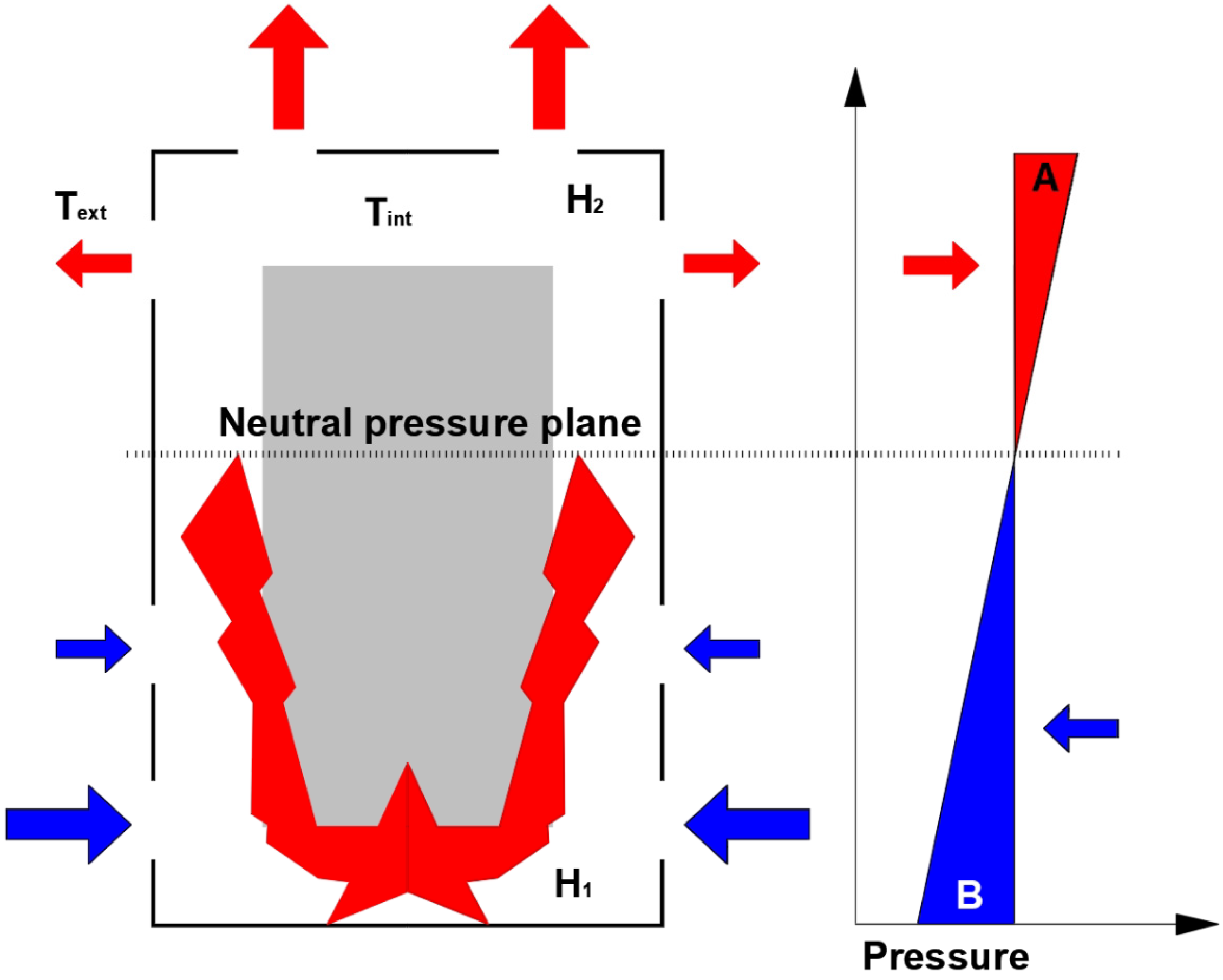
As was mentioned before, in the power plant buildings, especially in the boiler houses, there are constant sources of heat emission, which require the continuous and hi-effective operation of the natural ventilation system. The first step of the design process is recognizing the potential location of the heat source and the makeup air openings. As a result of the heat reaching the upper parts of the room, different pressure zones are created in its space. A pressure equalization appears at a certain height, representing the external pressure. The level of the pressure equalization is referred to as the “neutral pressure plane”, and its position depends on the total height of the room and the heat source position and size. Due to this, the ventilation openings placed above the neutral plane, where the internal pressure is higher than the external pressure, work as the exhaust vents, and those set below the neutral plane work as the air supply vents. The openings located precisely at the neutral plane level are ineffective. The neutral plane position and the functionings of the natural ventilation system are shown in
Figure 2 [
20,
21].
The airflow rate induced through the vents is calculated based on the pressure acting across it and its dimensions. It can be approximated by a power law equation of the form [
1]:
where:
Qm = mass flow through opening (kg/s);
r = density of the air flowing through the opening (kg/m3);
pext = pressure acting on the outside of the opening (Pa);
pint = pressure acting on the inside of the opening (Pa);
C = flow coefficient (related to the size of the opening and is normally expressed in terms of m3/s for each m2 of porous surface area or for each m length of the crack);
n = flow exponent (related to the type of flow in value between 0.5 for fully turbulent flow and 1.0 for completely laminar flow but is most often equal from 0.6 to 0.7).
The pressure distribution in buildings is generated by differences in temperature and air density between the inside and outside (
Figure 2). In industrial power plants, the indoor air temperature is greater than the outdoor temperature. Consequently, air flows into the building through the lower openings and out through the upper vents. The stack pressure between two vertically spaced openings, h
1 and h
2, is represented by the total horizontal displacement of the pressure curves at these levels (i.e., ‘A’ + ‘B’) by application of Ideal Gas Laws and is given by [
1]:
where:
ρ0 = air density at 273 K (1.29 kg/m3);
g = gravity acceleration (9.81 m/s2);
Text = outdoor air temperature (K);
Tint = indoor air temperature (K);
h1 = height of opening 1 (m);
h2 = height of the opening 2 (m).
The position of the neutral plane is not constant and changes with the height of the room and the heat source release rate. An example of the neutral plane height for the different heat sources in a boiler room tall of 100 m and a boiler room tall of 60 m is shown in
Table 1. It is visible that with the heat source size increasing, the neutral plane’s height decreases. This phenomenon indicates that the makeup air openings created daily and fire ventilation should always be located in the room’s lowest part. In the other case, when the heat source size drastically rises during a fire, the level of the neutral plane would radically go down, and too high of an opening location would create an opposite airflow direction.
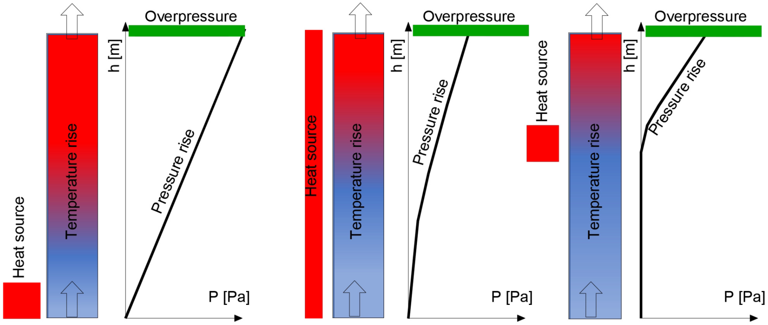
An essential role in the ventilation process also plays the heat source location in the room.
Figure 3 shows the increase in the internal room temperature and pressure differences, depending on the location of the heat source [
22].
Figure 3 shows that the highest temperature increase occurs under the roof when the heat source (fire source) is located at the top part of the building. On the contrary, the highest-pressure level occurs when the heat source is at the bottom. Based on this phenomenon, the most dangerous fire scenarios could be concluded depending on the performance-based objectives. In the building construction safety assessment, the most significant impact of fire on the structure of the building should be taken into account. It appears when the fire is located in the highest part of the room, and this scenario would be the worst-case scenario. In analyses related to the largest amount of smoke production and people’s evacuation safety analysis, fire on the floor should be taken into account. Detailed guidance on the smoke control systems assessment in the boiler and turbine buildings is set out below.
4. The Boiler House Smoke Control Systems
In boiler houses, due to the substantial daily heat emission, exhaust ventilation points should be located in the upper parts of the building. At the same time, it is necessary to ensure adequate fresh air supply openings at the bottom of the building.
4.1. Calculations of the Required Ventilation Parameters
The calculation criterion for determining the required active surface of the vents shall be the temperature under the boiler house ceiling acceptable for the existing devices. Based on the author’s experience, the critical temperature, which used to be taken into account, equals 40–50 °C.
Table 2 shows the active surface of heat-dissipation and the makeup air openings in the sample boiler house, depending on the amount of heat released and external air temperature, calculated with the Ventos Online application [
23], which is based on the equations presented above.
In the event of a fire, the same ventilation elements as for daily purposes are often used for smoke control. However, in the case of fire, it is necessary to consider a much larger heat emission (produced by fire) than for the daily situation. However, at the same time, during a fire, the critical temperature below the ceiling of the boiler house can usually increase to 350 °C, representing the level of tenability of the steel roof structure [
24].
Table 3 shows the maximal design fire size (convective heat release rate), which does not make the temperature above 350 °C under the roof in a boiler house of 100 m height when the same ventilation elements work for its daily ventilation.
4.2. CFD Analysis
The first step of the CFD simulations was a 3-dimensional model creation and boundary conditions definition. For the simulations, a computational grid of 0.3 m in the X, Y, and Z directions was adopted. The material of the building construction was concrete, with a density of 2.100 kg/m3, a thermal conductivity of 1.0 W/m·K, and a specific heat of 0.88 kJ/kg·K. In the analyses, the initial external and internal temperature was 20 °C.
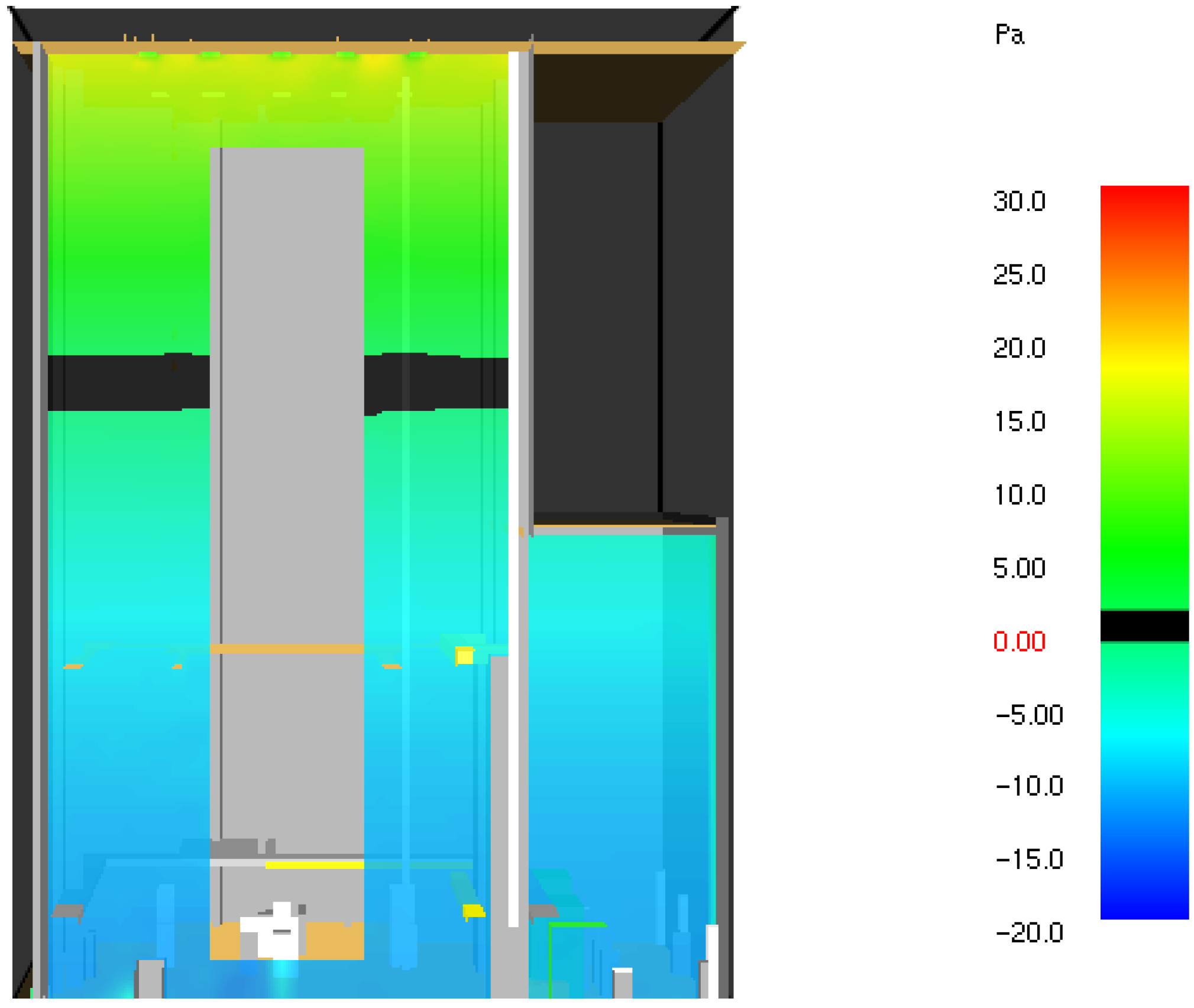
The phenomenon of the neutral plane position in the boiler house of 100 m height, described earlier, with a daily working heat emission of 15 MW is presented in
Figure 4. The simulation confirms that the neutral plane (black color) is located approximately in the middle of the building.
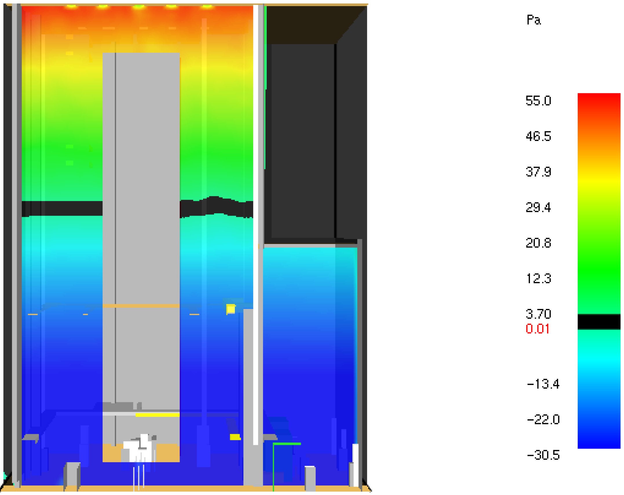
The subsequent analysis takes into account a fire scenario of 77 MW located at the floor level in the boiler house. In this scenario, the same ventilation system works as previously described. It is visible that the neutral plane decreases slightly, and at the same time, the pressure difference between the upper and lower boiler levels increases significantly (
Figure 5).
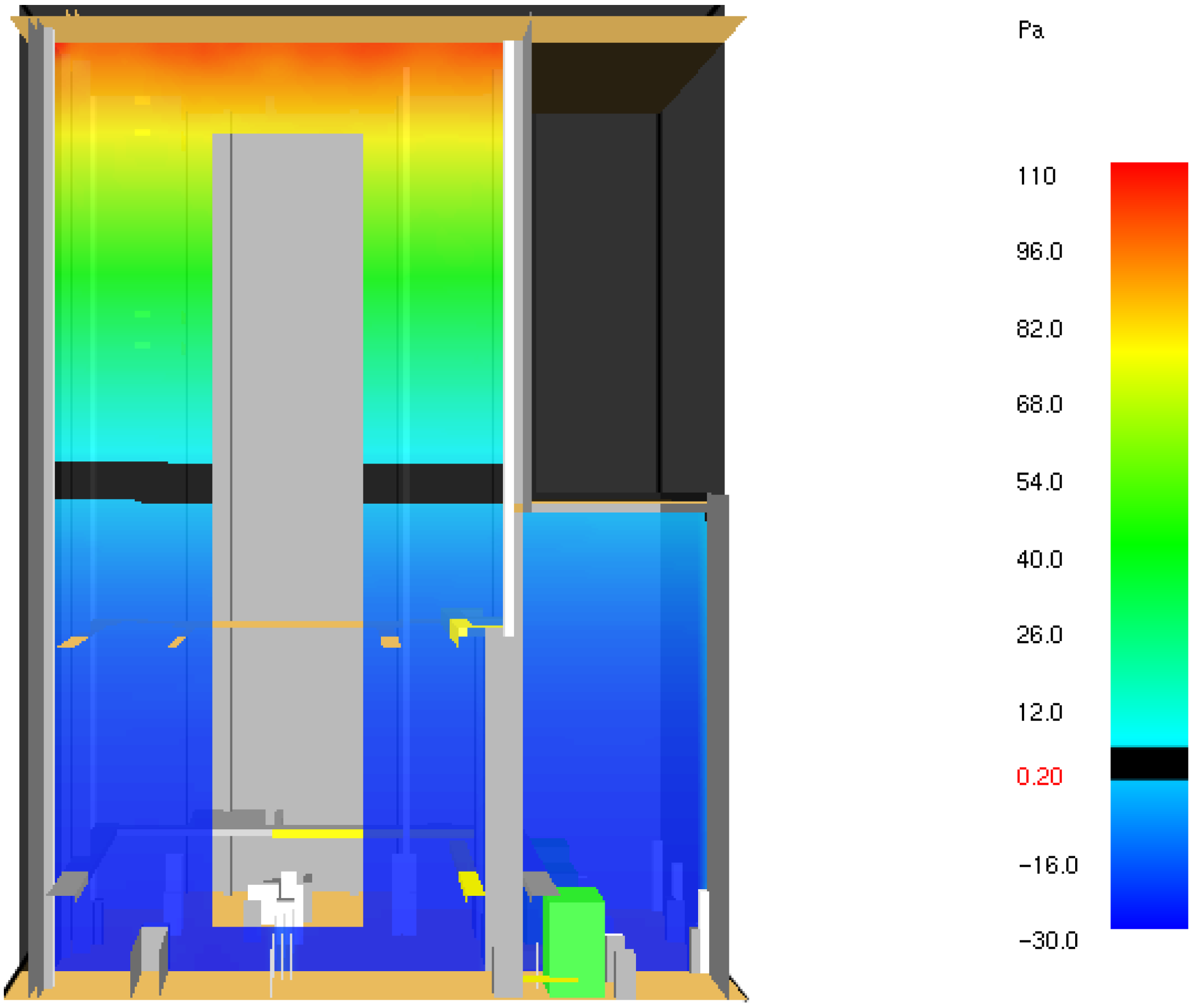
The most significant pressure increase under the boiler house roof could occur if ventilation remained closed under fire conditions, as demonstrated in
Figure 6.
The pressure gradients are visible in
Figure 4 and
Figure 5, which, in the case of the regular operation of the boiler house, are about 50 Pa, and in the event of a fire can increase significantly (here to 85 Pa), becoming a motor that produces the air or smoke buoyancy.
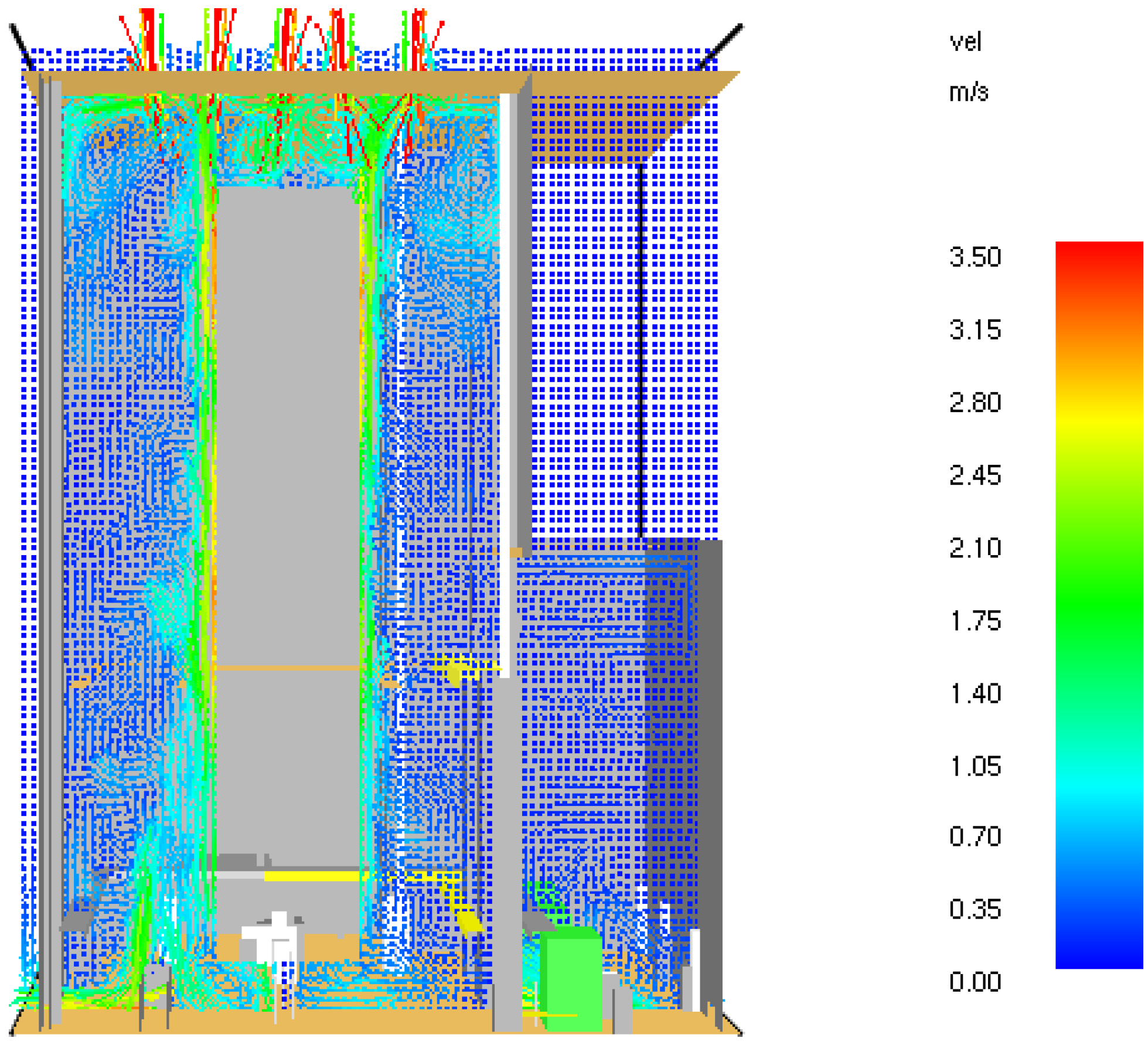
Figure 7 shows the distribution of air flows under normal boiler house conditions, with an active surface of the ventilation openings equal to 50 m
2.
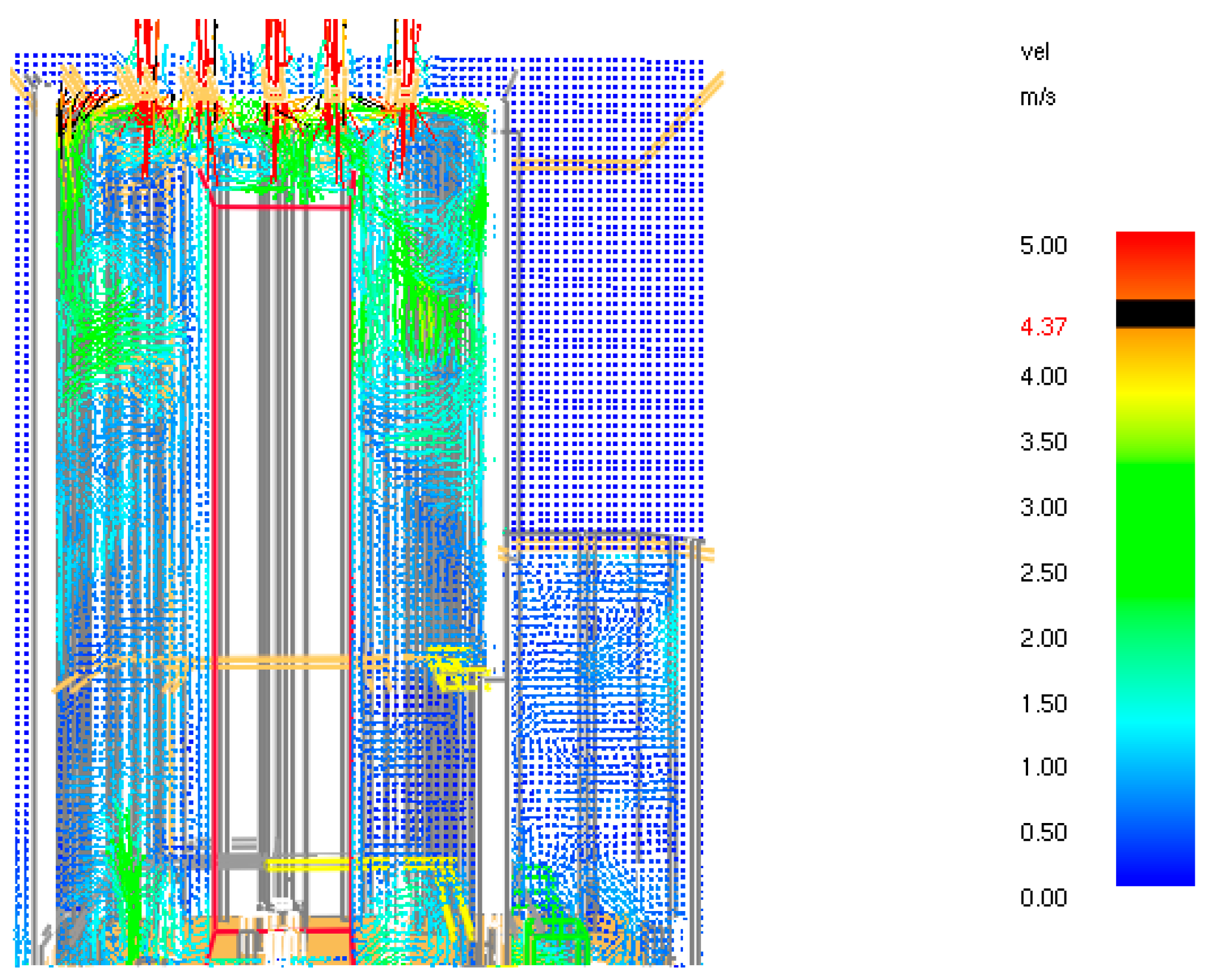
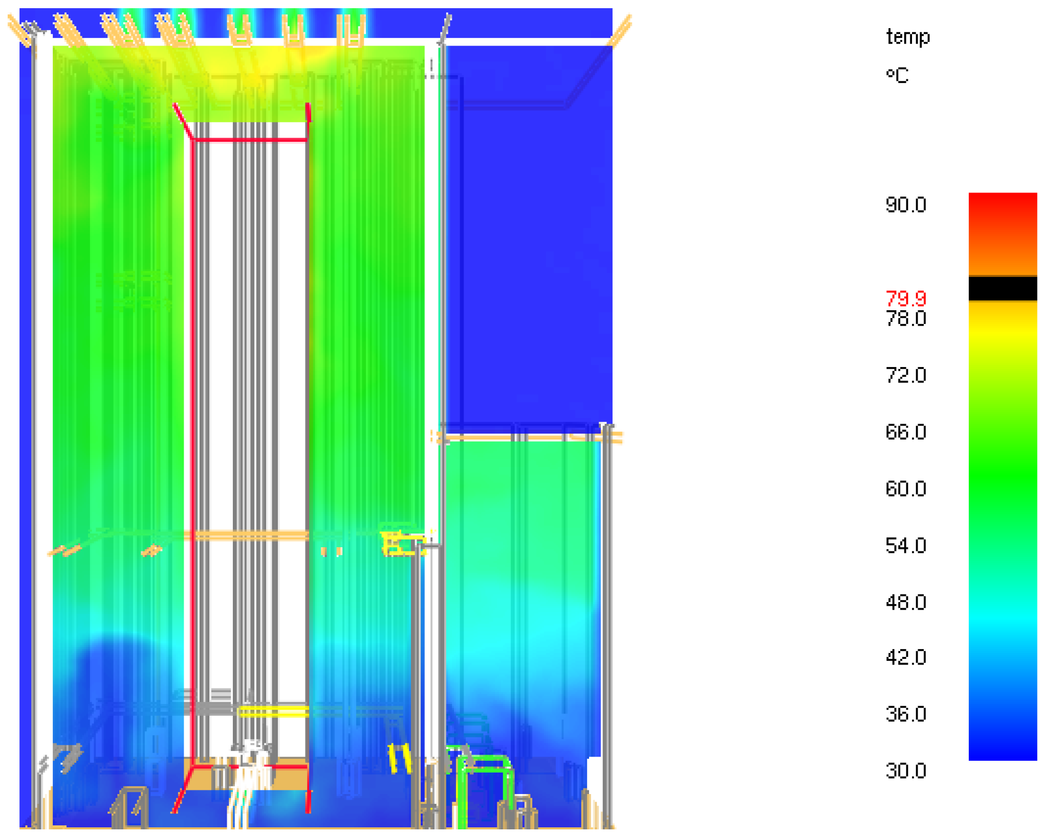
During an exemplar fire accident (HRR = 77 MW) in the boiler house, considered under the same ventilation conditions as above, the velocity of the ventilation air increases from about 3.5 m/s to over 5 m/s—nearly 50% (
Figure 8). At the same time, the temperature under the ceiling of the room does not reach the tenability limit of 350 °C, creating safe conditions for its construction (
Figure 9).
The above simulation results prove that the ventilation elements used in the daily conditions could also be helpful during a fire. At the same time, it is visible that despite the vast heights of these buildings, gravitational ventilation systems could work effectively here.
5. The Turbine Houses Smoke Control Systems
In the turbine house, intense heat is also emitted during daily operation, but much less than in the boiler house. This heat comes from turbines and other devices located there. Therefore, the turbine houses also require continuous ventilation. For this purpose, roof vents are used, mainly with the makeup air points near the floor.
5.1. Calculations of the Required Ventilation Parameters
The calculation criterion for determining the necessary active surface of the openings is the temperature level below the ceiling of the turbine house, which is acceptable for the equipment present there. As previously, tenability limits are 40–50 °C.
Table 4 shows the calculated active surface of the vents in the turbine house, depending on the internal heat release rate and the external temperature.
The daily ventilation equipment can also work as a smoke control system in a fire.
Table 5 shows the maximum convective fire heat release rate covered by the daily ventilation systems from
Table 4 in the 30 m high turbine house. In this case, a tenability limit for temperature is 350 °C, at which there is no risk of damage to the steel roof structure.
The received maximum convective fire heat release rates represent relatively big fires, which can be expected in the turbine houses. Consequently, it can be concluded that their daily ventilation systems could be expected to be sufficient here for smoke control. This applies primarily to modern turbine houses, where elements that pose a particular fire risk have individual fire-resistant enclosures and are protected by fixed fire extinguishing equipment, and the potential fire size is limited.
An additional problematic element in the turbine houses is their extraordinary length. This causes smoke to descend due to its cooling during a long under-roof flow. The division of turbine houses with smoke curtains into smoke zones is recommended to avoid this phenomenon.
5.2. CFD Analysis
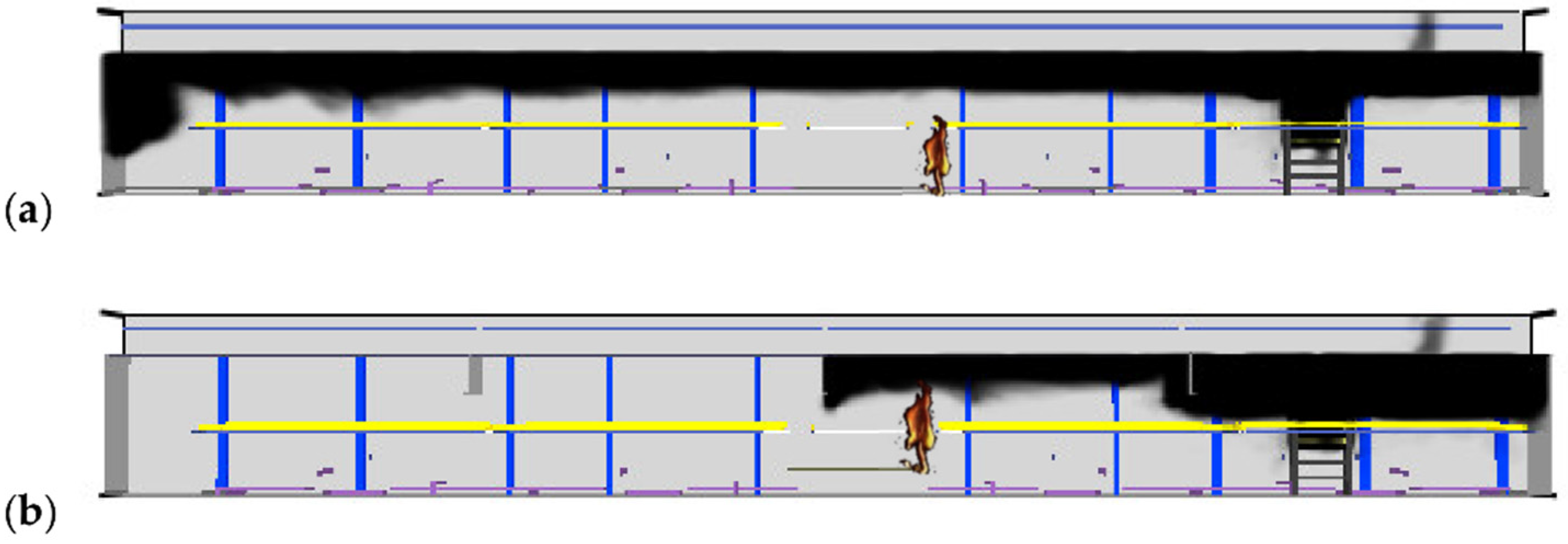
Figure 10 shows the differences in the smoke spread in the turbine house 180 m long and 30 m high during the first minutes of a fire.
Figure 10a presents the smoke layer decreasing when no smoke curtains were used, and
Figure 10b presents the smoke cumulation under the roof when 8 m long curtains were used. In the absence of curtains, decreasing smoke may cause difficulties for rescue teams to access the fire source. In both cases, smoke was produced during a very fast fire, developing to 21 MW, with smoke vents of 10 m
2. In the presented simulation results, a mixture of combustible materials were adopted, and the soot yield coefficient was 0.091 kg/kg.
6. Protection against the Propagation of Smoke into the Stairwells
Another problem in the boiler houses is their stairwells’ protection against smoke propagation. This is difficult due to their height of about 100 m, and consequently, the large pressure difference between their upper and lower parts caused by the chimney effect [
25]. The most difficult conditions for the stairwells’ protection against smoke appear in summer, when the high external temperature can cause a negative chimney effect and lack of effectiveness of gravitational smoke convective flows. In the upper part of the staircase, underpressure in reference to the external environment may be created in this situation. At the same time, in the upper part of the boiler house space, overpressure additionally increases in the event of a fire, as demonstrated in
Section 4.2. Consequently, the pressure difference between the stairwell and the boiler house space may be more than 100 Pa, and when the door opens to the staircase, the air (or, in the event of a fire—the smoke) is moved to the stairwell space. Although the stairwells in the boiler houses have vestibules on each level, this phenomenon still appears.
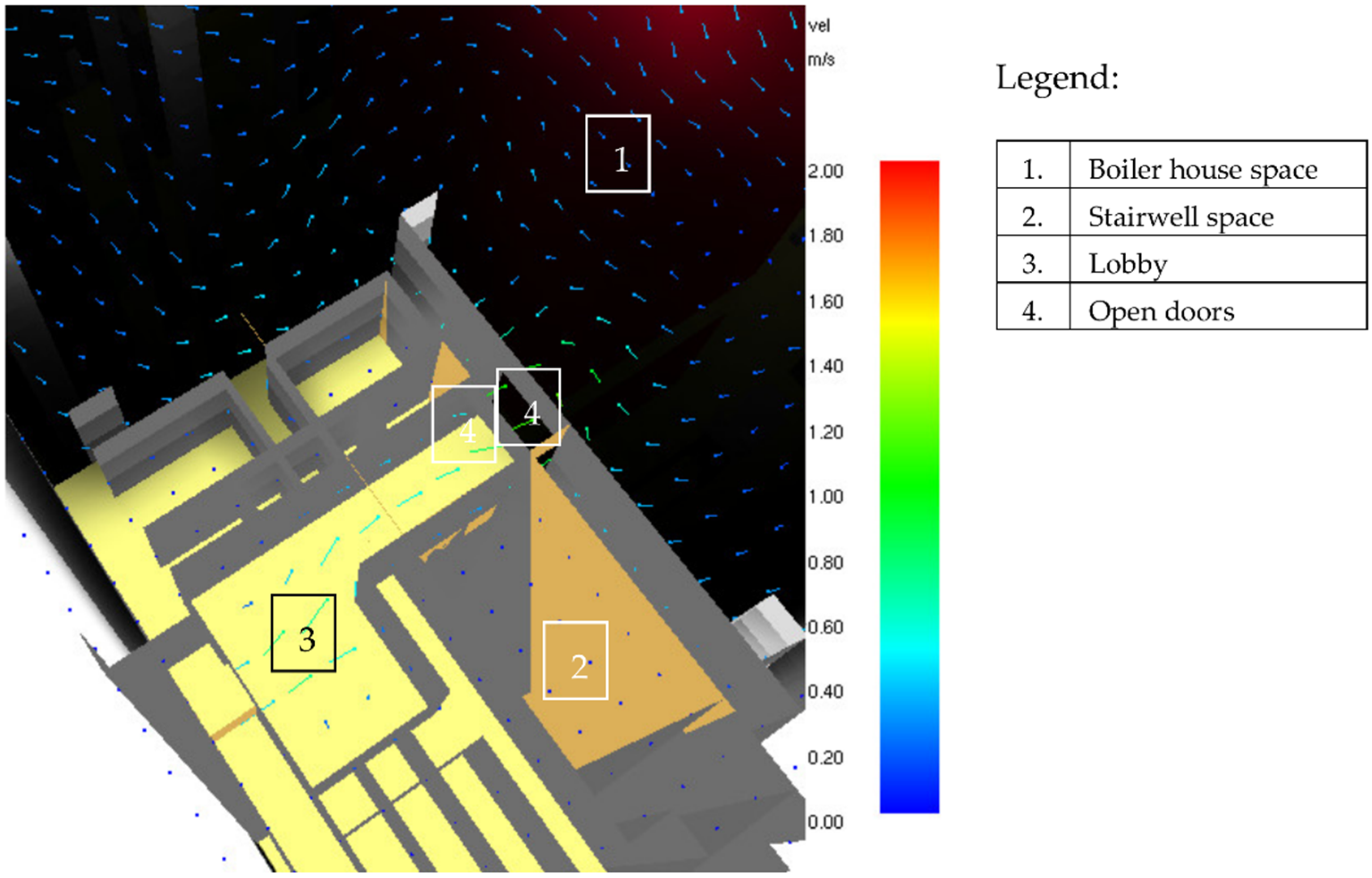
6.1. The Stairwell Situation in Nonventilated Conditions
Figure 11 presents a situation in which neither the boiler house space nor the vestibule’s smoke control was applied. It is visible that smoke rapidly enters the vestibule and the stairwell, making people’s evacuation impossible.
6.2. The Stairwell with Ventilated Vestibule
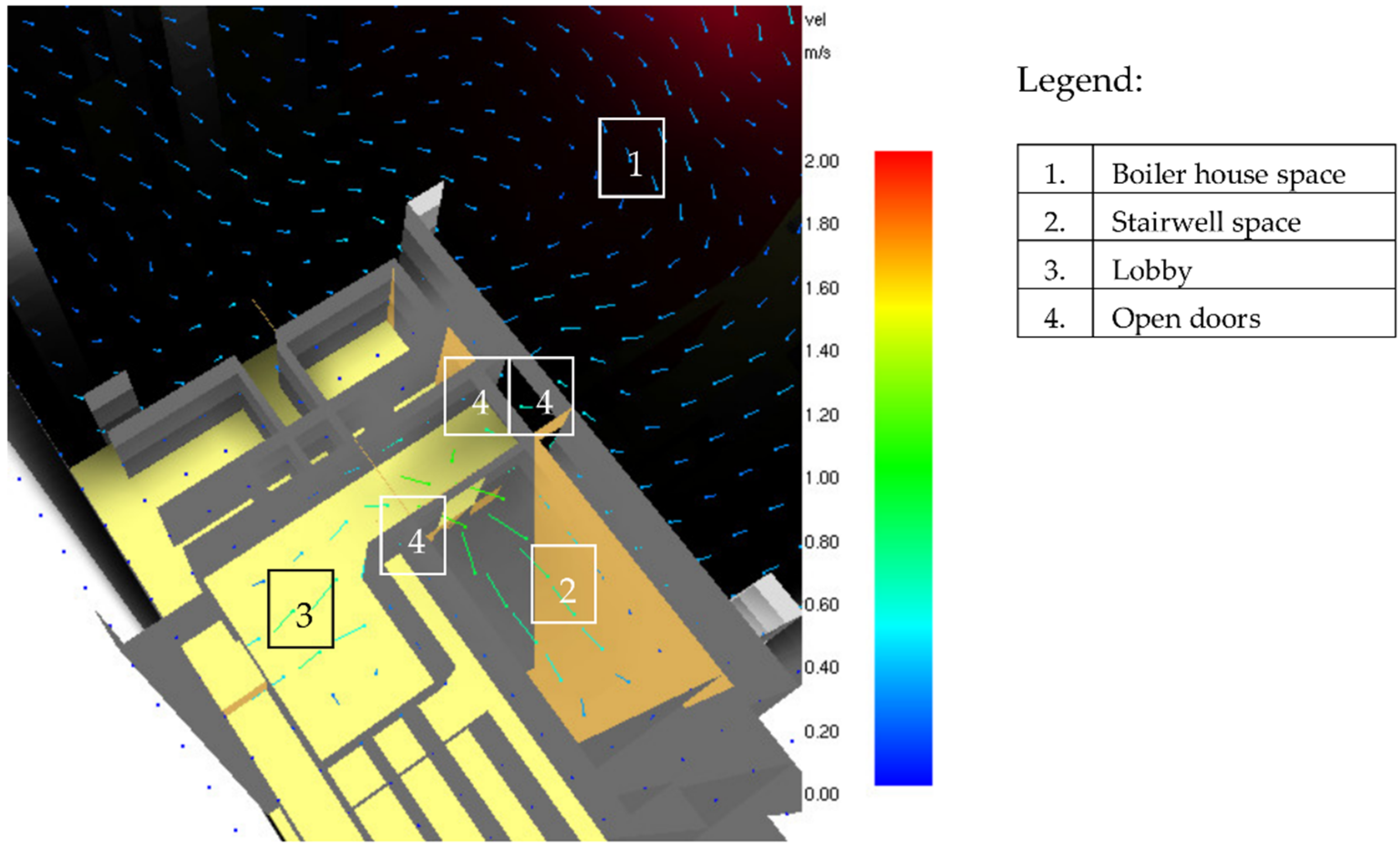
The best improvement solution is to use a mechanical air supply system to prevent the vestibules from smoke propagation, which simultaneously acts as stairwell protection.
Figure 12 shows how the air supply to the vestibule can work when the boiler room becomes smoky. The system provides the air velocity in the door between the vestibule and the boiler house space equal to 0.75 m/s, a standard velocity in pressurization systems [
26]. It is visible that such a solution can protect against smoke propagation to the vestibule and stairwell simultaneously. The simulation results represent conditions at the level of +70 m when the door to the vestibule door is opened.
6.3. The Overpressured Stairwell with Ventilated Vestibule
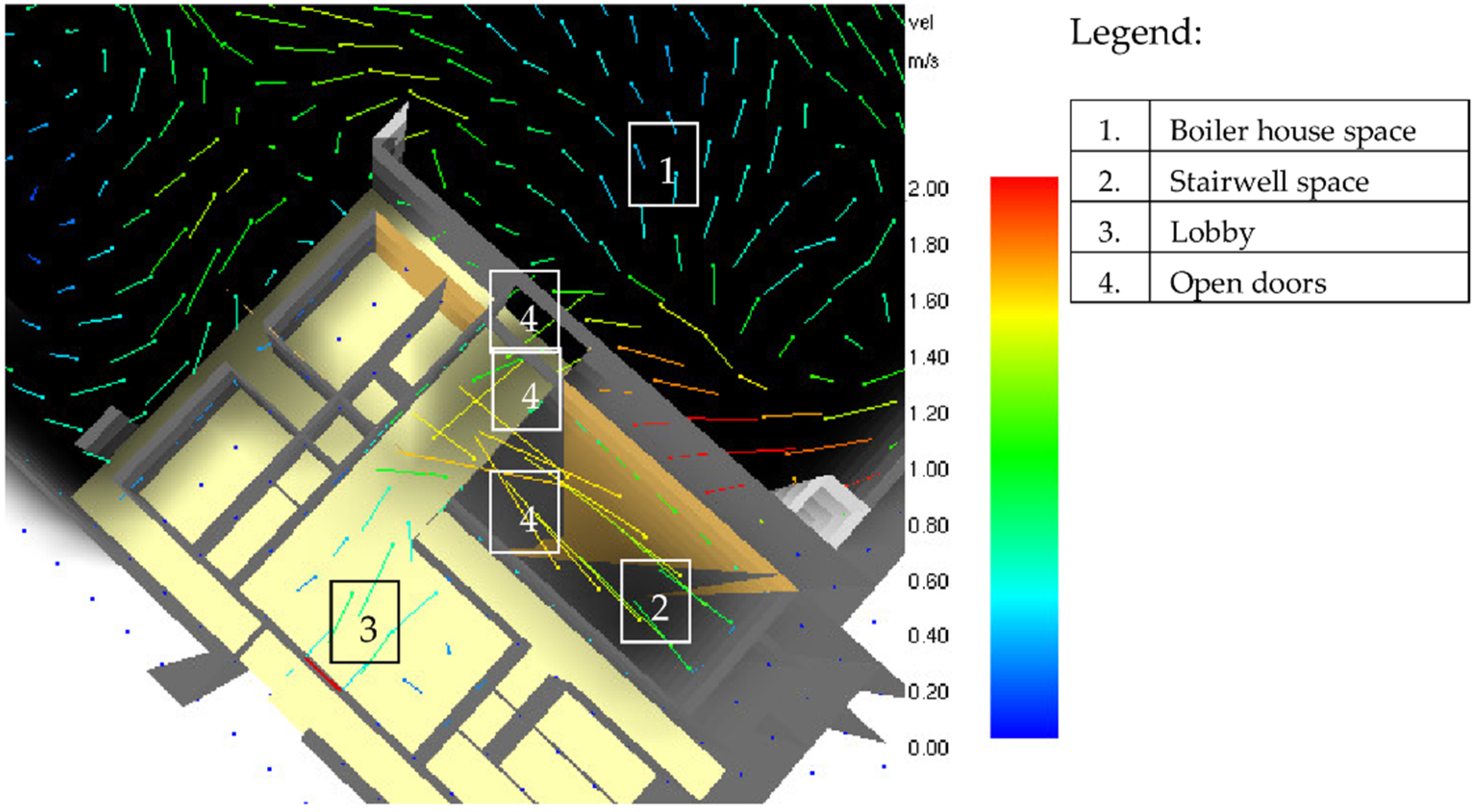
The question arises, what would happen when the door from the vestibule to the boiler house and the stairwell are opened together? Part of the air supplied to the vestibule then flows to the stairwell, decreasing the airflow to the boiler room. In this situation, there may be an inflow into the vestibule of some smoke. However, the smoke is removed immediately after the door to the stairwell is closed again (
Figure 13).
6.4. The Overpressured Stairwell with a Ventilated Vestibule in Nonventilated Boiler House
The final simulation represents the same door opening conditions as in
Figure 13. The boiler house smoke control system remains inactive (
Figure 14). Due to the higher overpressure in the boiler house, the smoke enters the vestibule and stairwell much more strongly. The standard stairwell protection is not effective enough.
7. Discussion and Conclusions
This article presents considerations on the efficiency of ventilation systems in the boiler and turbine houses in power stations. It demonstrates that in most cases, the daily ventilation systems used in the boiler houses become sufficient to smoke control in the event of a fire. However, it is essential to correctly place the smoke vents and air makeup openings, considering internal pressure conditions. Otherwise, an excessive increase in temperature and pressure may occur under the building’s roof space, posing a risk to the structure and the stairwells’ smoke propagation. The conducted analysis proved that there is no need for mechanical smoke control systems in the boiler houses. The natural thermal stack effect created there by the internal heat guarantees effective smoke dissipation, even in a relatively small fire with a rather cool smoke.
On the other hand, in turbine houses, due to their significant length, the creation of additional divisions into smoke zones (using fixed or movable smoke curtains) was suggested. Such a solution increases the efficiency of smoke ventilation (due to the higher temperature and the higher thickness of the smoke layer). It eliminates descending of the smoke layer caused by its cooling.
At the same time, it has been shown that sufficient staircase (pylons) protection can be realized with a modified pressurization system based on the air supply only to the vestibules.
The considerations set out in the article illustrate how many factors can significantly impact the conditions in the power station buildings during their daily operations or in the case of fire. Additionally, performance-based engineering tools using it in the field of optimal daily and smoke ventilation systems designing are presented.
Assuming the main findings of this article are:
- -
for correct ventilation system work, it is essential to establish a precise position of the exhaust and supply vents, considering a neutral pressure plane,
- -
natural ventilation systems are good enough in power stations,
- -
the daily ventilation systems used in the boiler houses can be sufficient to smoke control in the event of a fire, the stairwells in boiler houses can be protected against smoke propagation only by vestibule ventilation.

