Article

The Performance of the High-Current Transformer during Operation in the Wide Frequencies Range

Institute of Mechatronics and Information Systems, Lodz University of Technology, 90-537 Lodz, Poland
*
Author to whom correspondence should be addressed.
Energies 2022, 15(19), 7208; https://doi.org/10.3390/en15197208
Submission received: 18 August 2022 / Revised: 17 September 2022 / Accepted: 27 September 2022 / Published: 30 September 2022
(This article belongs to the Special Issue Development of Voltage and Current Transformers in Power System)

Abstract

:
This paper presents the performance of the 26 kVA inductive high-current transformer (HCT) during operation in the frequencies range of transformed harmonics from 50 Hz to 5 kHz. Performed research concerns the determination of the possibility of obtaining an order of the higher harmonic of a given RMS value in its distorted output current for the required RMS value of the main component and the maximum safe instantaneous value of the input voltage equal to 400 V. The results are presented for serial, serial-parallel and parallel configurations of primary and secondary windings (9 cases). Therefore, the most favourable configuration of the primary and secondary windings sections may be chosen. The tests are performed for the transformation of the distorted current containing a fundamental component and one higher harmonic of order from the 5th changed by the 5 up to the 100th. The constant 10% higher harmonic level in relation to the main component of the distorted secondary current is set. The measurements are performed for different resistances and inductances of the secondary winding’s load resulting from the length of the connected current track.

1. Introduction

The inductive high-current transformer (HCT) is used to step up current in the high-current test systems for the evaluation of the performance of current transformers, circuit breakers and power cables etc. It is composed of the toroidal magnetic core made from electrotechnical steel and primary and secondary windings divided into 4 sections. The configuration of the sections of the primary and secondary winding sets the input and output apparent power distribution between the current and voltage. The serial and parallel connection of sections in both windings will ensure the highest output voltage if increased impedance is connected to the secondary winding. The parallel connection of sections in the primary winding required the highest input current, but then only for the parallel connection of sections in the secondary winding was the rated apparent power of HCT available. The serial connection of its sections ensures 25% of the rated output apparent power and 25% of the rated output current is available. Distortion of the current in the power grid causes a need to perform the transformation accuracy test of measuring current transformers (CTs) in the wider frequencies range, not only for sinusoidal currents of 50 Hz (60 Hz) frequency [1,2,3,4,5,6,7,8,9,10,11,12,13]. This results from the fact that distorted active and reactive power is measured by the electricity meters and wideband metrological performance of instrument transformer is required to ensure their accurate measurements [14,15,16,17,18,19,20,21]. There are developed measuring systems for the evaluation of CT transformation accuracy for distorted current [4,5,7,8]. In the solutions presented in the papers [1,2,7,8,22], the tests are performed in the conditions of the rated ampere turns. In this case, the HCT is not required but this method is only applicable to window type CTs. This is because an additional primary winding has to be made. The required number of turns results from the rated current ratio of tested CT and its rated secondary current RMS value. The additional primary winding is supplied from the wideband amplifier or calibrator, which may ensure about 100 A or 12.5 A output current, respectively [4,5,23,24,25,26,27]. If bar type CT needs to be tested, the HCT is required. In such a measuring system, the source of the reference signal is also needed. For this purpose, specially designed wideband inductive CTs or electronic transducers may be used [6,28,29,30,31]. The primary circuits of the reference device and tested bar type CT are connected in series and fed with the rated current from the HCT. To perform the wideband accuracy test of CTs, it must be supplied from the programmable power source that enables the generation of distorted current containing an adjustable level of harmonics. In ref. [23], a comparison of the wideband power sources able to be applied to the suppling of the high-current transformer is presented. The first solution is based on the pulse width modulation inverter, while the second one is composed of an audio power amplifier and a two-channel arbitrary generator.
In this paper, the performance of the 26 kVA inductive HCT during operation in the frequencies range of the transformed harmonics from 50 Hz to 5 kHz is presented. The research concerns the determination of the possibility of obtaining an order of the higher harmonic of a given RMS value in its distorted output current for the required RMS value of the main component and the maximum safe instantaneous value of the input voltage equal to 400 V. The tests are performed for the transformation of the distorted current containing a fundamental component and one higher harmonic of order from the 5th changed by the 5 up to the 100th. The results are presented for serial, serial-parallel and parallel configurations of primary and secondary windings (9 cases). Therefore, the most favourable configuration of the primary and secondary windings sections may be chosen. The constant 10% higher harmonic level in relation to the main component of the distorted secondary current is set. The measurements are performed for different resistances and inductances of the secondary winding’s load resulting from the length of the connected current track equal to 6 m or 3 m. Tested HCT is supplied by the programmable power supply system. This limits the available input current to 20 A RMS. The leakage inductances of windings are the most important factors conditioning the performance of the HCT during operation in the wide frequencies range. Their values are determined for all available connections of sections. Therefore, the performance of the 26 kVA inductive HCT for the maximum input current of the primary winding for all available connections of its sections may be evaluated. Moreover, the improvements to the tested HCT construction to increase its distorted secondary current RMS value with 10% contribution of the higher harmonic in the frequencies range of operation up to 5 kHz are proposed.
The novelty of this paper is enumerated in the following bullet points:
  • determination of the wideband performance of the tested HCT and identification of the most favourable connection of sections of secondary and primary windings,
  • designation of the factors limiting the wideband operation of the inductive HCT with analysis of the influence of inductance and resistance of the load,
  • proposition of the improvements to the construction of the tested inductive HCT to increase its distorted output current RMS value,
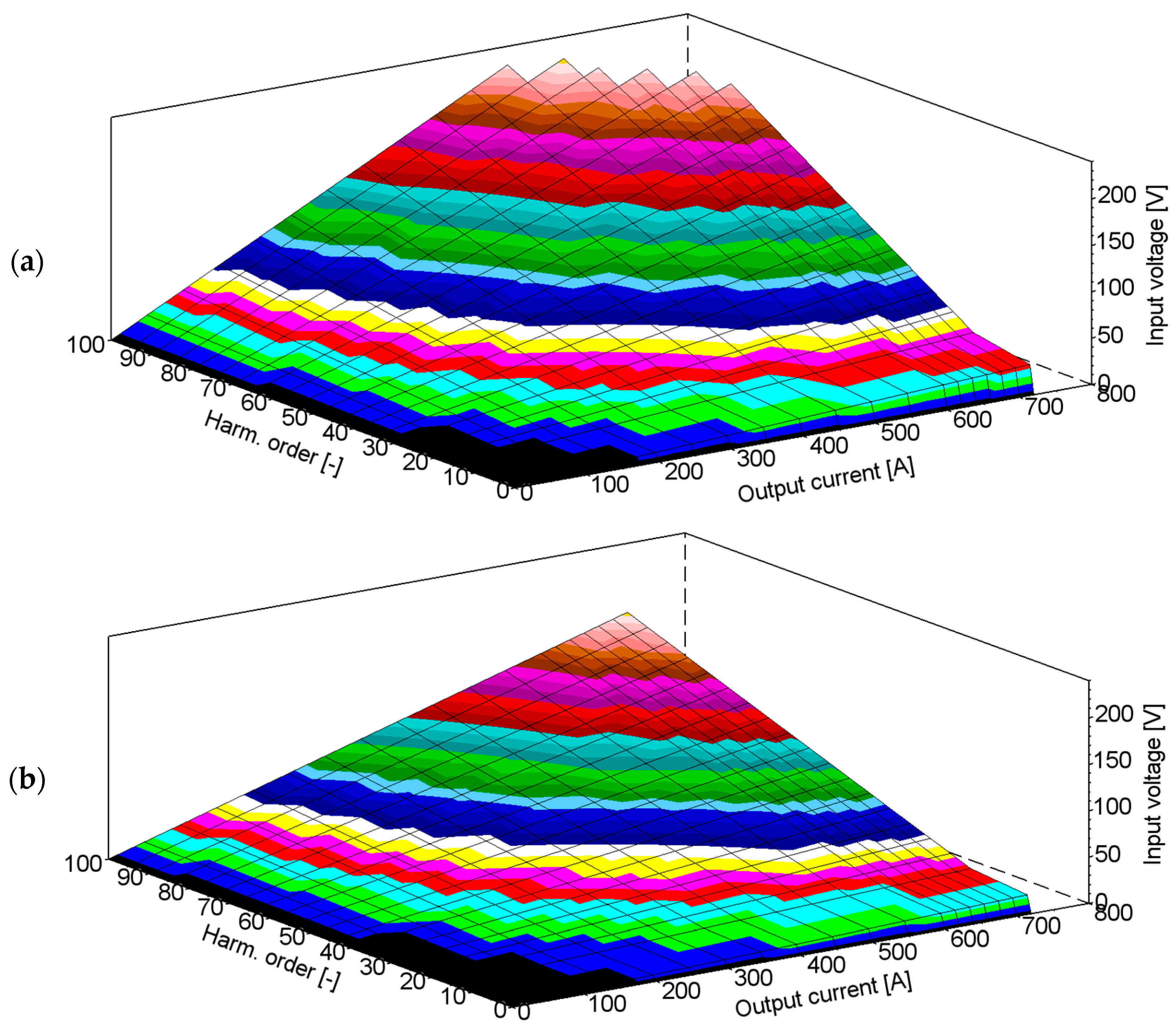
  • presentation of the relationship between the RMS value of the distorted output current with a given harmonic order and required RMS value of the input primary voltage,
  • designation of the negligibility of the influence of windings resistance and magnetic core excitation current on the wideband performance of the tested inductive HCT.

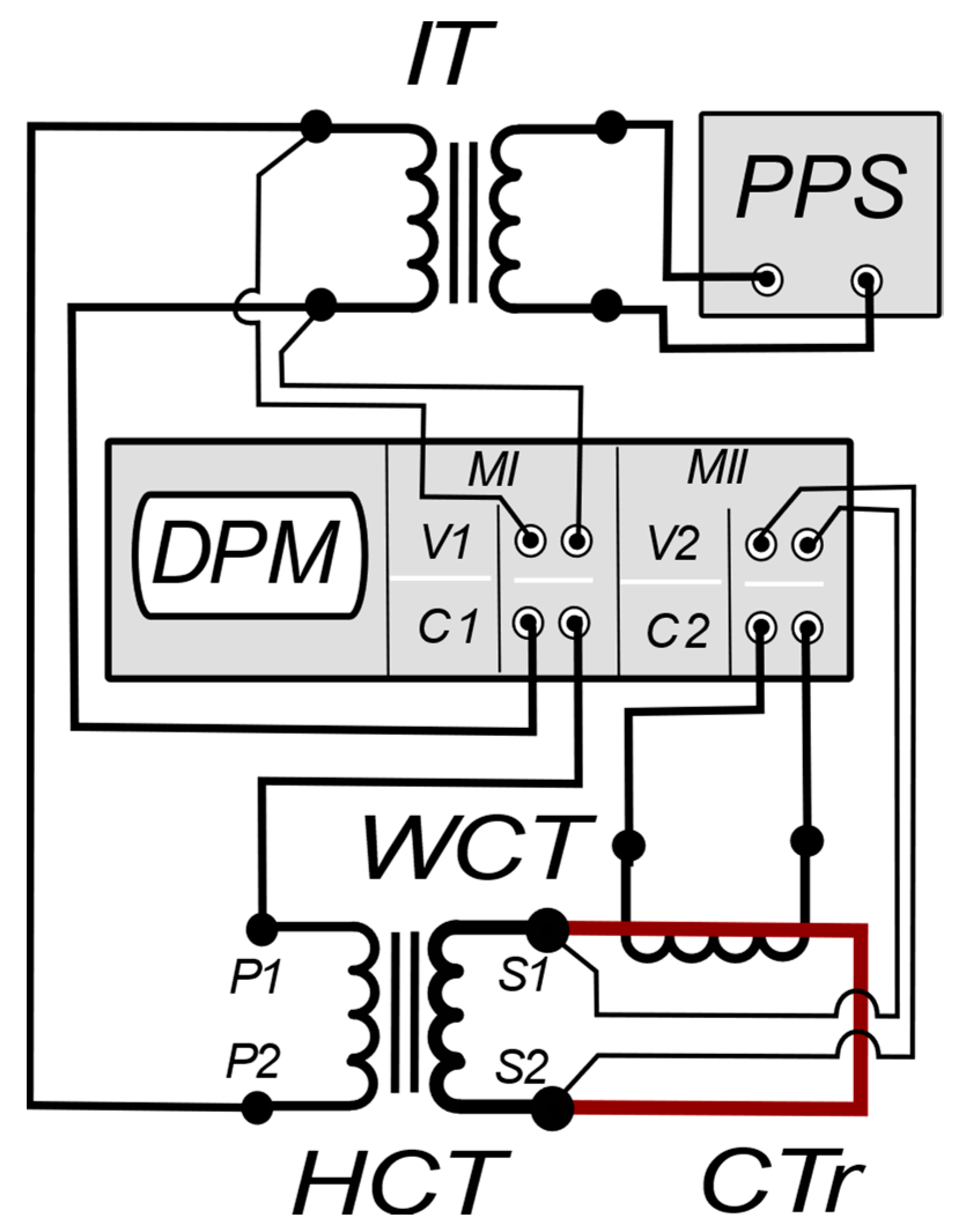
2. The Measuring Circuit and the Tested High-Current Transformer

The measuring circuit presented in Figure 1 is supplied by the programmable power supply system (PPS), enabling generation of the distorted currents [23,24]. To determine the wideband performance of the HCT, the digital power meter (DPM) with two measuring modules is used. Moreover, the DPM is able to perform the Fast Fourier Transform (FFT) of all the measured signals. The first DPM’s measuring module is connected to the primary side of the tested HCT, while the second one measures the secondary side voltage and current through the wideband current transformer (WCT). Utilisation of the WCT is required to transform the high value of the secondary current flowing in the current track (CTr). The WCT can operate in the wide frequency range with high metrological performance, as presented in the papers [1,8,32].
In Figure 1, the following abbreviations are used:
  • PPS—programmable power supply system,
  • DPM—digital power meter,
  • WCT—wideband current transformer,
  • HCT—high-current transformer,
  • CTr—current track,
  • MI/MII—I/II measuring module of the DPM,
  • V1/V2—1/2 voltage input,
  • C1/C2—1/2 current input,
  • P1/P2—terminals of the primary winding of the HCT,
  • S1/S2—terminals of the secondary winding of the HCT.
During the tests, the HCT is fed by the distorted input voltage with the maximum instantaneous value not exceeding 400 V. Therefore, the maximum instantaneous value of the generated higher harmonics is limited in accordance with the equation:
U m a x = 400   V = 230 2 sin 2 π 50 t + U m h k sin ω h k t + φ h k m a x ,
This limitation results from the maximum permitted electrical stress of the primary winding’s insulation. The tests were performed in the condition where the secondary current was distorted by a single higher harmonic with the percentage level equal to 10% of the main component. To conduct research on the wideband performance of the HCT, the analysis of its equivalent circuit presented in Figure 2 was performed.
In Figure 2, the following abbreviations are used:
The notation ″ means that the values are converted to the HCT’s secondary side.
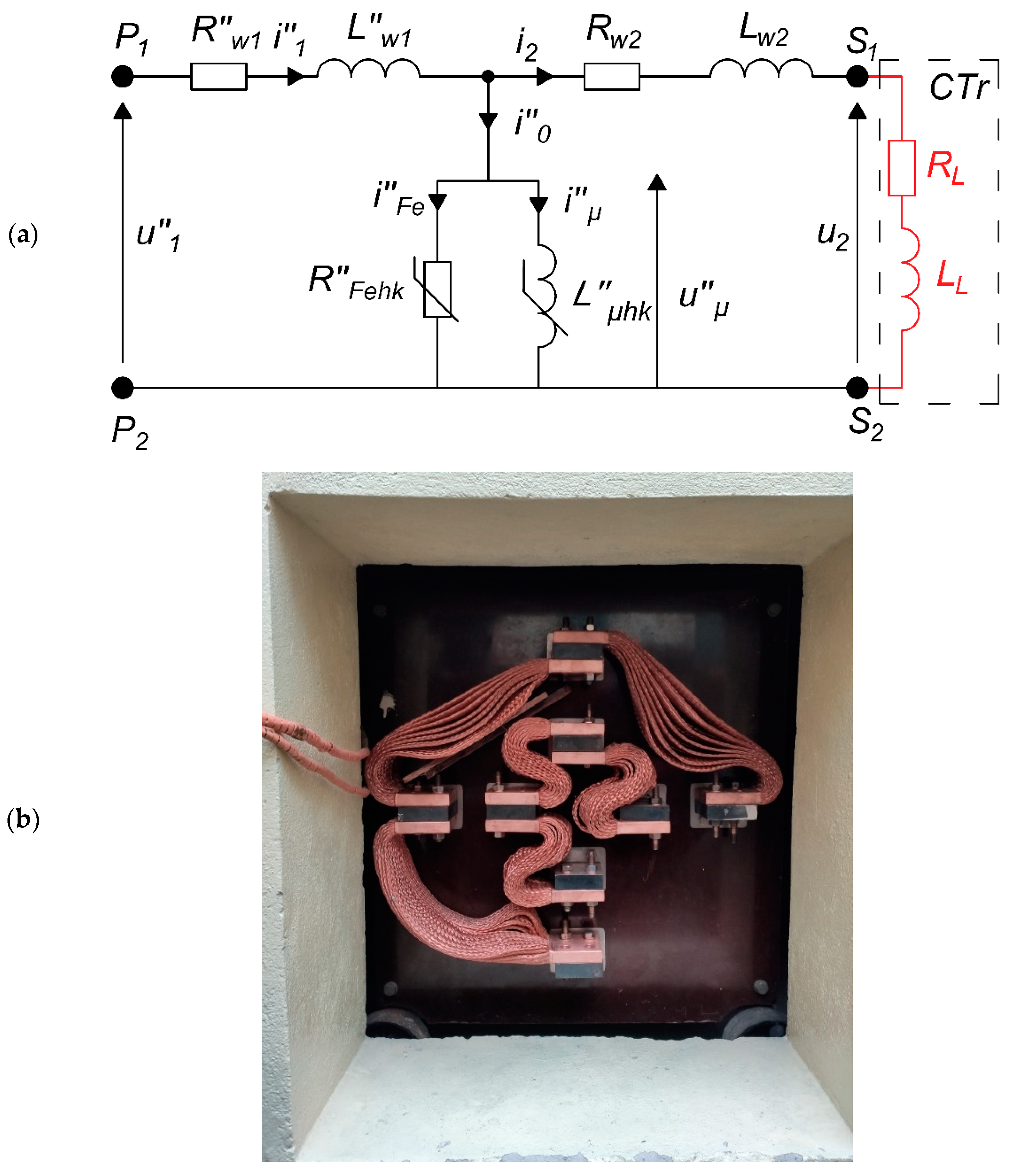
  • R″w1—resistance of the primary winding,
  • L″w1—leakage inductance of the primary winding,
  • Rw2—resistance of the secondary winding,
  • Lw2—leakage inductance of the secondary winding,
  • RL—resistance of the load associated with the current track,
  • LL—inductance of the load associated with the current track,
  • R″Fehk—resistance associated with active power losses of the magnetic core,
  • L″μhk—mutual inductance of the HCT’s windings,
  • i″1—instantaneous current of the HCT’s primary winding,
  • i″0—instantaneous excitation current of the HCT’s magnetic core,
  • i″μ—instantaneous reactive component of the excitation current,
  • i″Fe—instantaneous active component of the excitation current,
  • i2—instantaneous current of the HCT’s secondary winding,
  • u″1—instantaneous voltage of the HCT’s primary winding,
  • u″μ—instantaneous voltage associated with mutual inductance of the HCT’s windings,
  • u2—instantaneous voltage of the HCT’s secondary winding.
The main factors which are dependent on frequency, taking into consideration the equivalent circuit (Figure 2a), are reactances of the windings and load. The influence of the magnetic core on the wideband operation of the HCT is negligible due to the low value of the excitation current in relation to the primary current [33]. In such a case, the primary voltage converted to the secondary side may be calculated from the following equation:
u 1 = I 2 h 1 2 sin 2 π 50 t + I 2 h k 2 sin 2 π f h k t + φ h k R L + I 2 h 1 2 sin 2 π 50 t 2 π 50 L L + I 2 h k 2 sin 2 π f h k t + φ h k 2 π f h k L L + I 2 h 1 2 sin 2 π 50 t + I 2 h k 2 sin 2 π f h k t + φ h k R w 2 + I 2 h 1 2 sin 2 π 50 t 2 π 50 L w 2 + I 2 h k 2 sin 2 π f h k t + φ h k 2 π f h k L w 2 + I 1 h 1 2 sin 2 π 50 t + I 1 h k 2 sin 2 π f h k t + φ h k R w 1 + I 1 h 1 2 sin 2 π 50 t 2 π 50 L w 1 + I 1 h k 2 sin 2 π f h k t + φ h k 2 π f h k L w 1 ,
where:
  • hk—the order of higher harmonic component and
  • h1—the main component.
The RMS values of each harmonic component of the instantaneous primary voltage are calculated using FFT.
Considering used large windings and current track cross-section diameters, their values of resistance are also not an influence on the wideband operation of the HCT. These values are significantly lower than the reactances of the windings and current track. Therefore, the voltage drops on the resistances are negligible, also including the effect of their increase with the temperature and skin effect.
The windings of the HCT are divided into sections, with a single section of the primary winding having 36 turns and the secondary winding having 1 turn. Each winding consists of 4 sections, allowing parallel, serial-parallel and serial connection of them. Examples of primary and secondary winding section connections are presented in Figure 3.
In Figure 3, the following abbreviations are used:
The notation ″ means that the values are converted to the HCT’s secondary side.
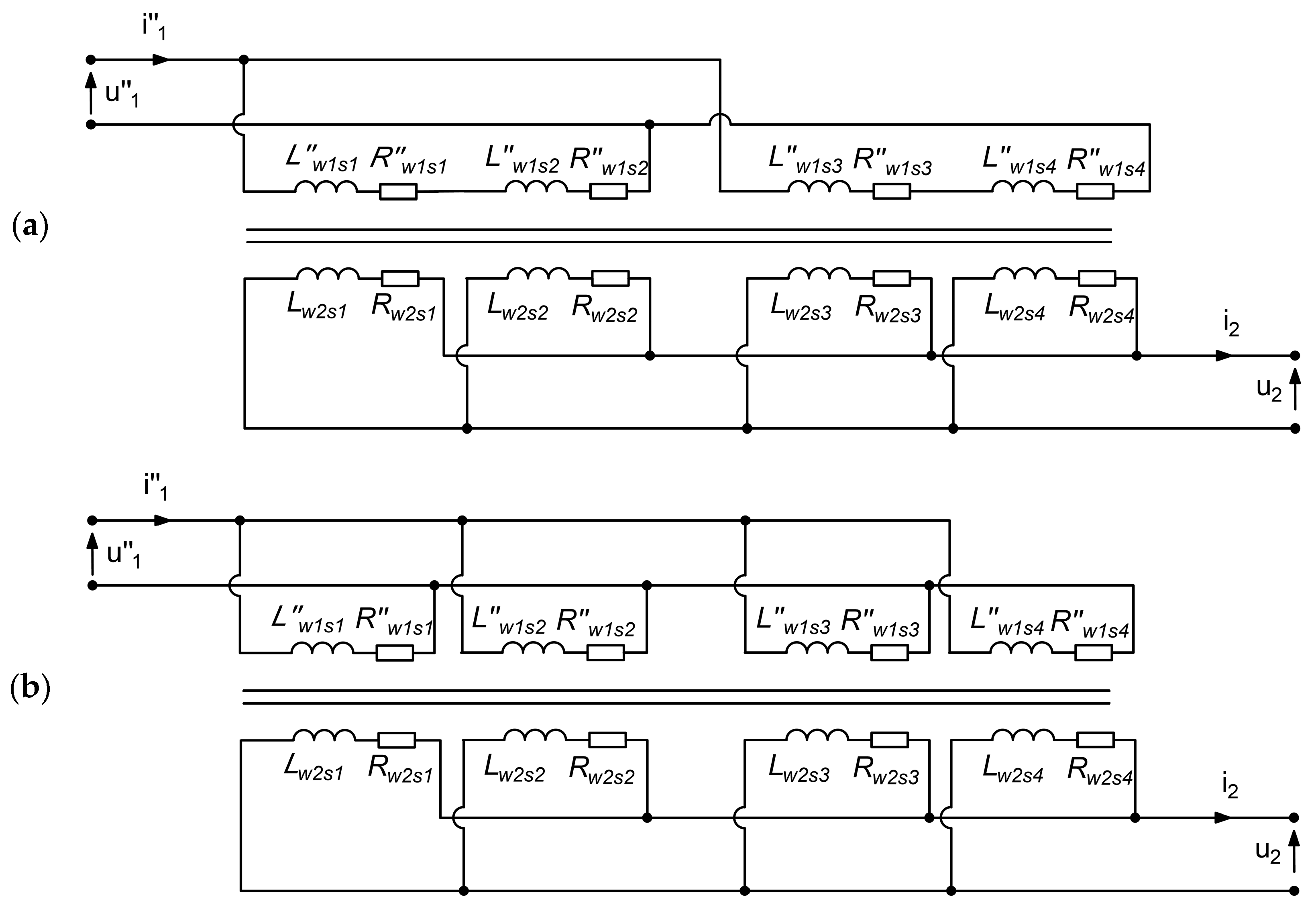
  • R″w1s1/R″w1s2/R″w1s3/R″w1s4—resistance of each section of the primary winding,
  • L″w1s1/L″w1s2/L″w1s3/L″w1s4—leakage inductance of each section of the primary winding,
  • Rw2s1/Rw2s2/Rw2s3/Rw2s4—resistance of each section of the secondary winding,
  • Lw2s1/Lw2s2/Lw2s3/Lw2s4—leakage inductance of each section of the primary winding.
The method of connecting the primary winding sections determines the power of the HCT by selecting the current supplied from the mains. The method in which the secondary winding sections are connected determines the permissible value of the current resulting from the multiple number of turns connected in parallel. The method in which the sections of the primary and the secondary windings are connected determines the current and voltage ratio of the HCT, defined based on the distribution of the output power between current and voltage.

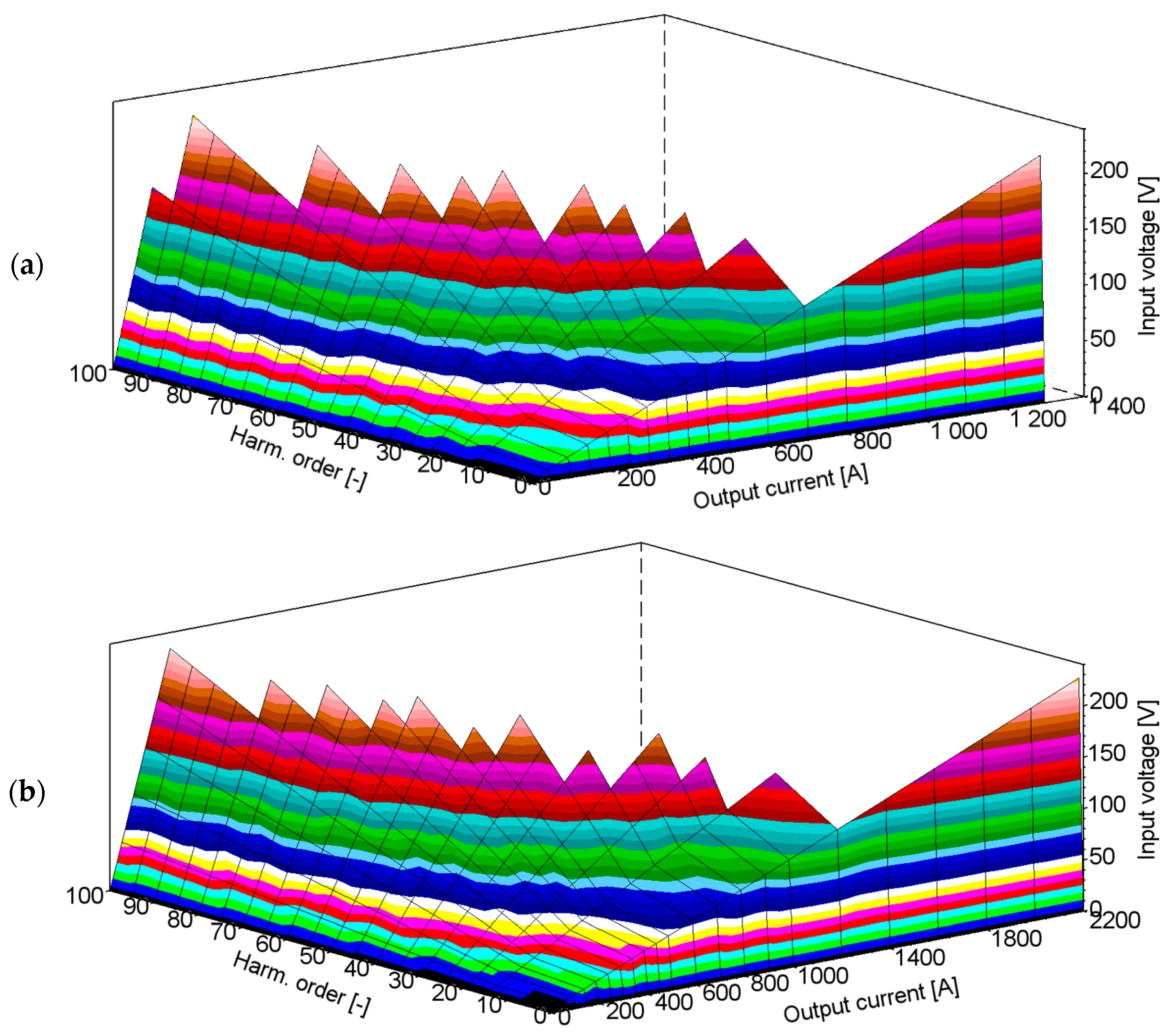
3. Measurement of the HCT’s Transformation Performance in the Wide Frequencies Range

The measurements were performed in the measuring circuit presented in Figure 1.
In all presented calculations of the values of the HCT’s output current, the excitation current was ignored. Therefore, its value results from the current ratio and may be expressed as:
i 1 = i 2 n ,
where:
  • n—current ratio equal to turns ratio.
The condition that must be met is that the calculated input voltage from Equation (2) does not exceed the maximum permissible input voltage defined by Equation (1). At the same time, the condition that the RMS values of the maximum input current does not exceed 28.5 A, 57 A and 114 A for serial, serial-parallel and parallel configuration of the primary winding’s section, respectively. In the overview of the results presented in Table 1, we compare maximum values, measured and calculated from Equation (3), of the obtained distorted secondary current where the whole frequency band of operation is ensured.
The cases where the required maximum instantaneous distorted primary voltage exceeds 400 V are shaded in the red colour. The cases where the measured distorted primary current exceeds 20 A RMS, which results from the maximum available output current of the programmable power supply system (PPS), are shaded in the green colour.
It results from the presented overview that the highest distorted output current with 10% of higher harmonics is obtained for configuration when the sections of the primary winding are connected in parallel and the secondary winding’s sections are also connected in parallel. Calculated values of the secondary currents maximally differ from the measured values by about 30 A. Therefore, without considering the magnetic core excitation current, we obtain sufficient accuracy when determining the RMS value of the distorted secondary current (it is shown in Table 1 that the calculation accuracy is not worse than 8%). The limitation shaded in red results from the high required voltage of the higher harmonic due to the reactances of the windings and the load. Therefore, the secondary voltage comes from the limited input voltage and the turns ratio of the HCT. If the turns ratio is high, the secondary voltage is low and if the turns ratio is lower, the secondary voltage is higher. The change of the turns ratio also changes the input current. If the secondary current has to be retained, the input current has to be increased, while the turns ratio has to be lowered.
The cases when the highest and the lowest values of the secondary current with an 100th order higher harmonic equal to 10% of the main component were obtained are marked in bolded font (Table 1) and presented in detail in Figure 4 and Figure 5.
In the above graph (in Figure 4a), for the case when the load of the secondary winding is equal to RL = 0.3 mΩ; LL = 3 μH and the applied maximum input current is equal to 9 A RMS, the output current is equal to 1300 A, but none of the higher harmonics may be obtained without exceeding the maximum RMS value of the input voltage. The operating bandwidth from 50 Hz to 5 kHz is obtained only for the highest 100 A RMS output current. This results from the required secondary voltage, which is increased with the order of the transformed higher harmonic. Considering the case presented in Figure 4b where the length of the current track is decreased, the RMS value of the output current for the analysed frequency range of operation of the tested HCT is increased to 250 A RMS. This is caused by the decrease of the inductance of the load, which thereby decreased the required RMS value of the output voltage.
The measured distorted output current with a given harmonic order for the supplied primary voltage obtained for parallel connection of the primary winding’s sections and parallel connection of the secondary winding’s sections for two different loads is presented in Figure 5.
In the above graph (in Figure 5a), for the case when the load of the secondary winding is equal to RL = 0.3 mΩ; LL = 3 μH and the applied maximum input current is equal to 20 A RMS, the output current is equal to 720 A, but this may only be obtained up to the 60th order of higher harmonics. Higher order requires exceeding the maximum RMS value of the input voltage. The operating bandwidth from 50 Hz to 5 kHz is obtained only for the highest 570 A RMS output current. Considering the case presented in Figure 5b where the length of the current track is decreased, the RMS value of the output current for the analysed frequency range of operation of the tested HCT is increased to 720 A RMS. This is the most favourable configuration of the HCT (parallel connection of the primary and secondary winding’s sections) when it is supplied by the programmable power supply system (PPS).

4. Calculation of the HCT’s Transformation Performance in the Wide Frequencies Range

In this paragraph, we present the results of the calculation of the HCT wideband performance in the cases when the primary current RMS value is limited only by the maximum input current resulting from the diameter of the wire used to make the primary winding. The values of the parameters of the equivalent circuit presented in Figure 2 required for calculations are determined in accordance with the method described in the paper [33]. The resistances of the windings are measured from the primary and secondary sides when the HCT is supplied by the direct current. The primary winding inductance is determined in the non-load state in the frequencies range from 50 Hz up to 5 kHz in accordance with the provided analysis of the vectorial diagrams. The secondary winding inductance is determined in the load state in the frequencies range from 50 Hz up to 5 kHz in accordance with the provided analysis of the vectorial diagrams. The results show a one percent deviation in the measured values. The overview of the calculated maximum values of the secondary current with an 100th order higher harmonic equal to 10% of the main component and obtained maximum higher harmonic order for the secondary current equal to 1000 A is presented in Table 2. The analysis is presented for four loads of the HCT’s secondary winding, where for the first three, only inductance of the current track is changed and in the last case, only the resistance is changed.
The cases where the required maximum instantaneous distorted primary voltage exceeds 400 V are shaded in the red colour. The cases where the required primary current exceeds 28.5 A RMS for the serial connection of the primary winding’s sections, 57 A RMS for the serial-parallel connection of the primary winding’s sections and 114 A RMS for the parallel connection of the primary winding’s sections are shaded in the green colour.
When more current is available from the mains, the turns ratio has to be reduced; then, the secondary voltage will be higher, and the secondary current will increase in the considered frequency band of the HCT’s operation. If turns of the primary winding are equal to 18 and turns of the secondary winding are equal to 1 turn for the maximum available current, from the mains equal to 114 A RMS, the operation of the HCT in the order up to the 100th higher harmonic of the secondary current equal to 2000 A with a load RL = 0.3 mΩ; LL = 1.5 μH will be obtained. When the maximum instantaneous value of the primary voltage is increased to 600 V, it is possible to achieve a distorted current equal to 2600 A RMS with the maximum order of the 100th higher harmonic considering the limitation of the current input value equal to 114 A RMS with turns ratio equal to 23 (1 turn of the secondary winding). If the same limitation of the maximum values of the primary voltage is assumed and the limitation of the supplied current is increased to 175 A RMS with reduced turns ratio to 18, the distorted secondary current will be equal to 3150 A RMS with a set bandwidth of higher harmonics up to the 100th order.
The cases when the highest and the lowest values of the secondary current with a 100th order higher harmonic equal to 10% of the main component were determined are marked in bolded font and presented in detail in Figure 6 and Figure 7.
In the above graph (in Figure 6a), for the case when the load of the secondary winding is equal to RL = 0.3 mΩ; LL = 3 μH and the applied maximum input current is equal to 28.5 A RMS, the output current is equal to 1350 A, but none of the higher harmonics may be obtained without exceeding the maximum RMS value of the input voltage. This is the maximum permissible value of the secondary current when the sections of the primary winding are connected in serial. The operating bandwidth from 50 Hz to 5 kHz is obtained only for the highest 150 A RMS output current. This results from the required secondary voltage which is increased with the order of the transformed higher harmonic. Considering the case presented in Figure 6b where the inductance of the load is decreased, the RMS value of the output current for the analysed frequency range of operation of the tested HCT is increased to 270 A RMS. In the case presented in Figure 6c for increased value of the inductance, the lower RMS values of the secondary current (80 A) is obtained. Presented diagrams are useful to determine the maximum RMS value of the distorted output current of the HCT for any assumed maximum order of the higher harmonic equal to 10% of the main component.
The calculated distorted output current with a given harmonic order for the supplied primary voltage obtained for the parallel connection of the primary winding’s sections and serial-parallel connection of the secondary winding’s sections for three configurations of load are presented in Figure 7.
In the above graph (in Figure 7a), for the case when the load of the secondary winding is equal to RL = 0.3 mΩ; LL = 3 μH and the applied maximum input current is equal to 114 A RMS, the output current is equal to 2050 A, but this may only be obtained up to the 40th order of the higher harmonic. Higher order requires exceeding the maximum RMS value of the input voltage. This is the maximum permissible value of the secondary current when the sections of the primary winding are connected in parallel. The operating bandwidth from 50 Hz to 8 kHz is obtained only for the highest 600 A RMS output current. This results from the required secondary voltage, which is increased with the order of the transformed higher harmonic. Considering the case presented in the Figure 6b where the inductance of the load is decreased, the RMS value of the output current for the analysed frequency range of operation of the tested HCT is increased to 800 A RMS. In the case presented in Figure 6c for increased values of the inductance, the lower RMS values of the secondary current (300 A) are obtained. In these cases, the maximum available RMS value of the input current from the mains is limited to 114 A. Therefore, the parallel configuration of both winding’s sections provides 1060 A RMS with higher harmonics of order up to the 100th. This limitation results from the maximum permissible input voltage defined by Equation (1). Reduction of the turns ratio by decreasing the number of turns of the primary winding for an increased input current from the mains provides better distribution of the output power of the HCT between the current and voltage. Therefore, for the parallel configuration of the section of the primary and secondary windings, a higher distorted output current will be obtained.

5. Conclusions

This paper presents a simple method for the evaluation of the HCT wide frequency performance. Presented graphs enable determination of the maximum RMS value of the distorted output current with an assumed value of 10% of the higher harmonic component, defined in relation to the RMS value of the main component. This allows for identification of the most favourable connection of sections of secondary and primary windings. This paper presents the relationship between the RMS value of the distorted output current with a given harmonic order and the required RMS value of the input primary voltage. Moreover, the conducted analysis shows factors limiting the wideband operation of the inductive HCT with consideration of the influence of the inductance and resistance of the load. Comparison of the results of the measurements and calculations indicates a negligibility of the influence of windings resistance and magnetic core excitation current on the wideband performance of the tested inductive HCT. Provided discussion of the obtained results allows one to deduce the proposition of the improvements to the construction of the tested inductive HCT to increase its distorted output current RMS value. The most favourable conditions may be obtained for parallel configuration of sections of the primary and secondary windings with a decreased number of turns of the primary winding. However, this requires an increase in the value of the input current from the mains. The second option is to increase the maximum instantaneous distorted primary voltage, which results from the maximum allowable electric stress of the primary winding’s insulation.

Author Contributions

Conceptualisation, M.K. and E.S.; methodology, M.K. and E.S.; validation, M.K. and E.S. formal analysis, M.K., P.K. and E.S.; investigation, M.K., P.K. and E.S.; resources, M.K. and E.S.; data curation, M.K., P.K. and E.S.; writing—original draft preparation, M.K. and E.S.; writing—review and editing, M.K. and E.S.; visualisation, E.S.; supervision, M.K. All authors have read and agreed to the published version of the manuscript.

Funding

This research received no external funding.

Data Availability Statement

Not applicable.

Conflicts of Interest

The authors declare no conflict of interest.

References

  1. Stano, E.; Kaczmarek, P.; Kaczmarek, M. Why Should We Test the Wideband Transformation Accuracy of Inductive Current Transformers? Energies 2022, 15, 5737. [Google Scholar] [CrossRef]
  2. Stano, E.; Kaczmarek, P.; Kaczmarek, M. Understanding the Frequency Characteristics of Current Error and Phase Displacement of the Corrected Inductive Current Transformer. Energies 2022, 15, 5436. [Google Scholar] [CrossRef]
  3. Crotti, G.; Chen, Y.; Çayci, H.; D’Avanzo, G.; Landi, C.; Letizia, P.S.; Luiso, M.; Mohns, E.; Muñoz, F.; Styblikova, R.; et al. How Instrument Transformers Influence Power Quality Measurements: A Proposal of Accuracy Verification Tests. Sensors 2022, 22, 5847. [Google Scholar] [CrossRef] [PubMed]
  4. Crotti, G.; Delle Femine, A.; Gallo, D.; Giordano, D.; Landi, C.; Letizia, P.S.; Luiso, M. Calibration of Current Transformers in distorted conditions. J. Phys. Conf. Ser. 2018, 1065, 052033. [Google Scholar] [CrossRef]
  5. Cristaldi, L.; Faifer, M.; Laurano, C.; Ottoboni, R.; Toscani, S.; Zanoni, M. A Low-Cost Generator for Testing and Calibrating Current Transformers. IEEE Trans. Instrum. Meas. 2019, 68, 2792–2799. [Google Scholar] [CrossRef]
  6. Kaczmarek, M.; Szczęsny, A.; Stano, E. Operation of the Electronic Current Transformer for Transformation of Distorted Current Higher Harmonics. Energies 2022, 15, 4368. [Google Scholar] [CrossRef]
  7. Kaczmarek, M.; Stano, E. The Influence of the 3rd Harmonic of the Distorted Primary Current on the Self-Generation of the Inductive Current Transformers. IEEE Access 2022, 10, 55876–55887. [Google Scholar] [CrossRef]
  8. Stano, E.; Kaczmarek, M. Wideband self-calibration method of inductive cts and verification of determined values of current and phase errors at harmonics for transformation of distorted current. Sensors 2020, 20, 2167. [Google Scholar] [CrossRef]
  9. Kaczmarek, M.; Stano, E. Nonlinearity of Magnetic Core in Evaluation of Current and Phase Errors of Transformation of Higher Harmonics of Distorted Current by Inductive Current Transformers. IEEE Access 2020, 8, 118885–118898. [Google Scholar] [CrossRef]
  10. Kaczmarek, M. Estimation of the inductive current transformer derating for operation with distorted currents. Bull. Polish Acad. Sci. Technol. Sci. 2014, 62, 363–366. [Google Scholar] [CrossRef] [Green Version]
  11. Kaczmarek, M. Wide frequency operation of the inductive current transformer with Ni80Fe20 toroidal core. Electr. Power Compon. Syst. 2014, 42, 1087–1094. [Google Scholar] [CrossRef]
  12. Ghaderi, A.; Mingotti, A.; Peretto, L.; Tinarelli, R. Procedure for ratio error and phase displacement prediction of inductive current transformers at different operating conditions. In Proceedings of the I2MTC 2020—International Instrumentation and Measurement Technology Conference, Dubrovnik, Croatia, 25–28 May 2020. [Google Scholar]
  13. Mingotti, A.; Peretto, L.; Bartolomei, L.; Cavaliere, D.; Tinarelli, R. Are inductive current transformers performance really affected by actual distorted network conditions? An experimental case study. Sensors 2020, 20, 927. [Google Scholar] [CrossRef] [PubMed]
  14. Murray, R.; De Kock, J. Instrument transformers influence on harmonic measurements for grid code compliance. In Proceedings of the 2018 IEEE 4th Global Electromagnetic Compatibility Conference (GEMCCON), Stellenbosch, South Africa, 7–9 November 2018. [Google Scholar]
  15. Dirik, H.; Duran, I.U.; Gezegin, C. A Computation and Metering Method for Harmonic Emissions of Individual Consumers. IEEE Trans. Instrum. Meas. 2019, 68, 412–420. [Google Scholar] [CrossRef]
  16. Zobaa, A.F.; Abdel Aleem, S.H.E. A new approach for harmonic distortion minimization in power systems supplying nonlinear loads. IEEE Trans. Ind. Inform. 2014, 10, 1401–1412. [Google Scholar] [CrossRef]
  17. Yang, T.; Pen, H.; Wang, D.; Wang, Z. Harmonic analysis in integrated energy system based on compressed sensing. Appl. Energy 2016, 165, 583–591. [Google Scholar] [CrossRef]
  18. Vieira, D.; Shayani, R.A.; De Oliveira, M.A.G. Reactive Power Billing under Nonsinusoidal Conditions for Low-Voltage Systems. IEEE Trans. Instrum. Meas. 2017, 66, 2004–2011. [Google Scholar] [CrossRef]
  19. Liang, X. Emerging Power Quality Challenges Due to Integration of Renewable Energy Sources. IEEE Trans. Ind. Appl. 2017, 53, 855–866. [Google Scholar] [CrossRef]
  20. Hossain, E.; Tur, M.R.; Padmanaban, S.; Ay, S.; Khan, I. Analysis and Mitigation of Power Quality Issues in Distributed Generation Systems Using Custom Power Devices. IEEE Access 2018, 6, 16816–16833. [Google Scholar] [CrossRef]
  21. da Silva, R.P.B.; Quadros, R.; Shaker, H.R.; da Silva, L.C.P. Effects of mixed electronic loads on the electrical energy systems considering different loading conditions with focus on power quality and billing issues. Appl. Energy 2020, 277, 115558. [Google Scholar] [CrossRef]
  22. Cataliotti, A.; Cosentino, V.; Crotti, G.; Giordano, D.; Modarres, M.; Di Cara, D.; Tinè, G.; Gallo, D.; Landi, C.; Luiso, M. Metrological performances of voltage and current instrument transformers in harmonics measurements. In Proceedings of the I2MTC 2018—2018 IEEE International Instrumentation and Measurement Technology Conference: Discovering New Horizons in Instrumentation and Measurement, Houston, TX, USA, 14–17 May 2018; pp. 1–6. [Google Scholar]
  23. Kaczmarek, M.; Kaczmarek, P. Comparison of the wideband power sources used to supply step-up current transformers for generation of distorted currents. Energies 2020, 13, 1849. [Google Scholar] [CrossRef]
  24. Brodecki, D.; Stano, E.; Andrychowicz, M.; Kaczmarek, P. Emc of wideband power sources. Energies 2021, 14, 1457. [Google Scholar] [CrossRef]
  25. Collin, A.J.; Femine, A.D.; Gallo, D.; Langella, R.; Luiso, M. Compensation of current transformers’ nonlinearities by tensor linearization. IEEE Trans. Instrum. Meas. 2019, 68, 3841–3849. [Google Scholar] [CrossRef]
  26. D’Avanzo, G.; Delle Femine, A.; Gallo, D.; Landi, C.; Luiso, M. Impact of inductive current transformers on synchrophasor measurement in presence of modulations. Meas. J. Int. Meas. Confed. 2020, 155, 107535. [Google Scholar] [CrossRef]
  27. Laurano, C.; Toscani, S.; Zanoni, M. A simple method for compensating harmonic distortion in current transformers: Experimental validation. Sensors 2021, 21, 2907. [Google Scholar] [CrossRef]
  28. Liang, C.T.; Chen, K.L.; Tsai, Y.P.; Chen, N. New electronic current transformer with a self-contained power supply. IEEE Trans. Power Deliv. 2015, 30, 184–192. [Google Scholar] [CrossRef]
  29. McNeill, N.; Dymond, H.; Mellor, P.H. High-fidelity low-cost electronic current sensor for utility power metering. IEEE Trans. Power Deliv. 2011, 26, 2309–2317. [Google Scholar] [CrossRef]
  30. Tong, Y.; Liu, B.; Abu-Siada, A.; Li, Z.; Li, C.; Zhu, B. Research on calibration technology for electronic current transformers. In Proceedings of the 2018 Condition Monitoring and Diagnosis (CMD), Perth, WA, Australia, 23–26 September 2018; pp. 1–5. [Google Scholar]
  31. Huang, G.J.; Chen, N.; Chen, K.L. Self-calibration method for coreless Hall effect current transformer. In Proceedings of the IEEE Power and Energy Society General Meeting, Boston, MA, USA, 17–21 July 2016; pp. 1–5. [Google Scholar]
  32. Kaczmarek, M.; Stano, E. Proposal for extension of routine tests of the inductive current transformers to evaluation of transformation accuracy of higher harmonics. Int. J. Electr. Power Energy Syst. 2019, 113, 842–849. [Google Scholar] [CrossRef]
  33. Kaczmarek, M.L.; Stano, E. Application of the inductive high current testing transformer for supplying of the measuring circuit with distorted current. IET Electr. Power Appl. 2019, 13, 1310–1317. [Google Scholar] [CrossRef]
Figure 1. Measuring circuit used to determine the wideband performance of the HCT.
Energies 15 07208 g001
Figure 2. (a) Equivalent circuit of the HCT, (b) Photo of the HCT’s secondary side.
Energies 15 07208 g002
Figure 3. Examples of primary and secondary winding section connections: (a) serial-parallel, primary and parallel secondary winding sections, (b) parallel primary and parallel secondary winding sections, (c) serial primary and serial secondary winding sections.
Energies 15 07208 g003aEnergies 15 07208 g003b
Figure 4. The measured distorted output current with a given harmonic order for supplied primary voltage obtained for serial connection of the primary winding’s sections and parallel connection of the secondary winding’s sections: (a) RL = 0.3 mΩ; LL = 3 μH, (b) RL = 0.2 mΩ; LL = 1.5 μH.
Energies 15 07208 g004
Figure 5. The measured distorted output current with a given harmonic order for the supplied primary voltage obtained for parallel connection of the primary winding’s sections and parallel connection of the secondary winding’s sections: (a) RL = 0.3 mΩ; LL = 3 μH, (b) RL = 0.2 mΩ; LL = 1.5 μH.
Energies 15 07208 g005
Figure 6. The calculated distorted output current with a given harmonic order for the supplied primary voltage obtained for serial connection of the primary winding’s sections and parallel connection of the secondary winding’s sections: (a) RL = 0.3 mΩ; LL = 3 μH, (b) RL = 0.3 mΩ; LL = 1.5 μH, (c) RL = 0.3 mΩ; LL = 6 μH.
Energies 15 07208 g006aEnergies 15 07208 g006b
Figure 7. The calculated distorted output current with a given harmonic order for the supplied primary voltage obtained for the parallel connection of the primary winding’s sections and the serial-parallel connection of the secondary winding’s sections: (a) RL = 0.3 mΩ; LL = 3 μH, (b) RL = 0.3 mΩ; LL = 1.5 μH, (c) RL = 0.3 mΩ; LL = 6 μH.
Energies 15 07208 g007aEnergies 15 07208 g007b
Table 1. Overview of the measured and calculated maximum values of the secondary current with the 100th order of higher harmonic equal to a 10% value of the main component.
Configuration of the Sections of the Primary WindingConfiguration of the Sections of the Secondary WindingCurrent RatioRL [mΩ]LL [μH]Measured Max Current with 10% of 100th Harm. [A]Calculated Max Current with 10% of 100th Harm. [A]
serialserial360.33.0350380
0.21.5490520
serial-parallel720.33.0270260
0.21.5455430
parallel1440.33.0145150
0.21.5255270
serial-parallelserial180.33.0360360
0.21.5360360
serial-parallel360.33.0535520
0.21.5720720
parallel720.33.0290300
0.21.5510540
parallelserial90.33.0180180
0.21.5180180
serial-parallel180.33.0360360
0.21.5360360
parallel360.33.0570590
0.21.5720720
Table 2. Overview of the calculated maximum values of the secondary current with 100th order higher harmonic equal to 10% of the main component and obtained maximum higher harmonic order for the secondary current equal to 1000 A.
Configuration of the Sections of the Primary WindingConfiguration of the Sections of the Secondary WindingCurrent Ratio
[–]
Rw1 [mΩ]Lw1 [μH]Rw2 [mΩ]Lw2 [μH]RL [mΩ]LL [μH]Max Harm. Order for 1000 AMax Current with 10% of 100th Harmonic [A]
serialserial360.170.610.641.750.33.037th380
1.552th520
6.024th240
3.03.037th380
serial-parallel720.040.150.240.700.33.026th260
1.543th430
6.014th150
3.03.026th260
parallel1440.010.040.140.320.33.015th150
1.527th270
6.08th80
3.03.014th150
serial-parallelserial180.130.820.641.750.33.072th720
1.599th990
6.047th470
3.03.072th720
serial-parallel360.030.200.240.700.33.052th520
1.584th840
6.029th290
3.03.052th520
parallel720.010.050.140.320.33.030th300
1.554th540
6.016th160
3.03.030th300
parallelserial90.071.410.641.750.33.0132th1030
1.5175th1030
6.088th880
3.03.0132th1026
serial-parallel180.020.350.240.700.33.0100th1000
1.5158th1580
6.057th570
3.03.0100th1000
parallel360.0050.090.140.320.33.060th600
1.5106th1060
6.032th320
3.03.060th600
Publisher’s Note: MDPI stays neutral with regard to jurisdictional claims in published maps and institutional affiliations.

