

Estimation and Comparison of SOC in Batteries Used in Electromobility Using the Thevenin Model and Coulomb Ampere Counting


Abstract
:1. Introduction
2. Electric Batteries
- Lithium-ion;
- Nickel metal hydride (NIMH);
- Lead Acid.
3. Methodology and Characterization of Batteries
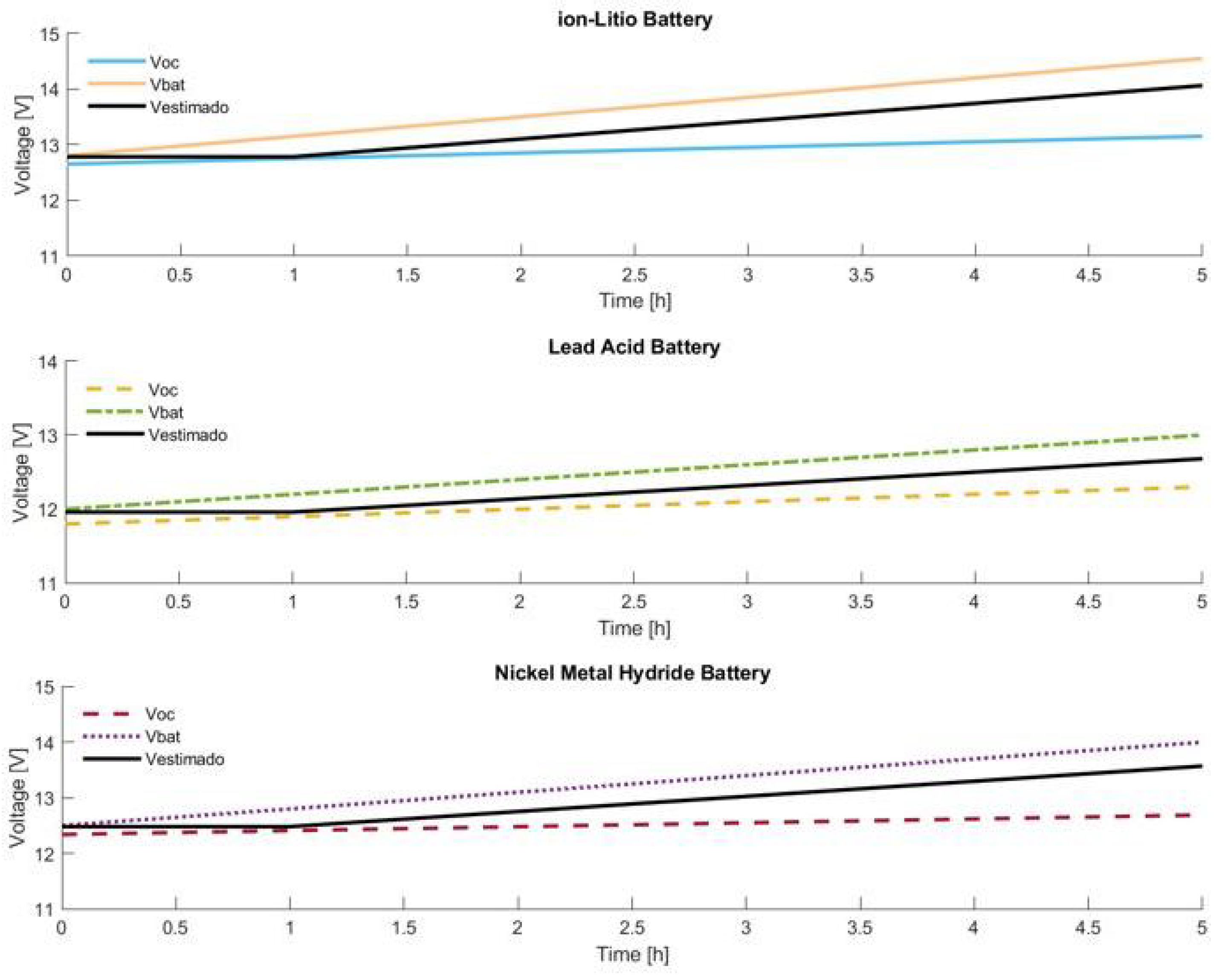
Internal Battery Voltage (Vco) on Charge
4. Results
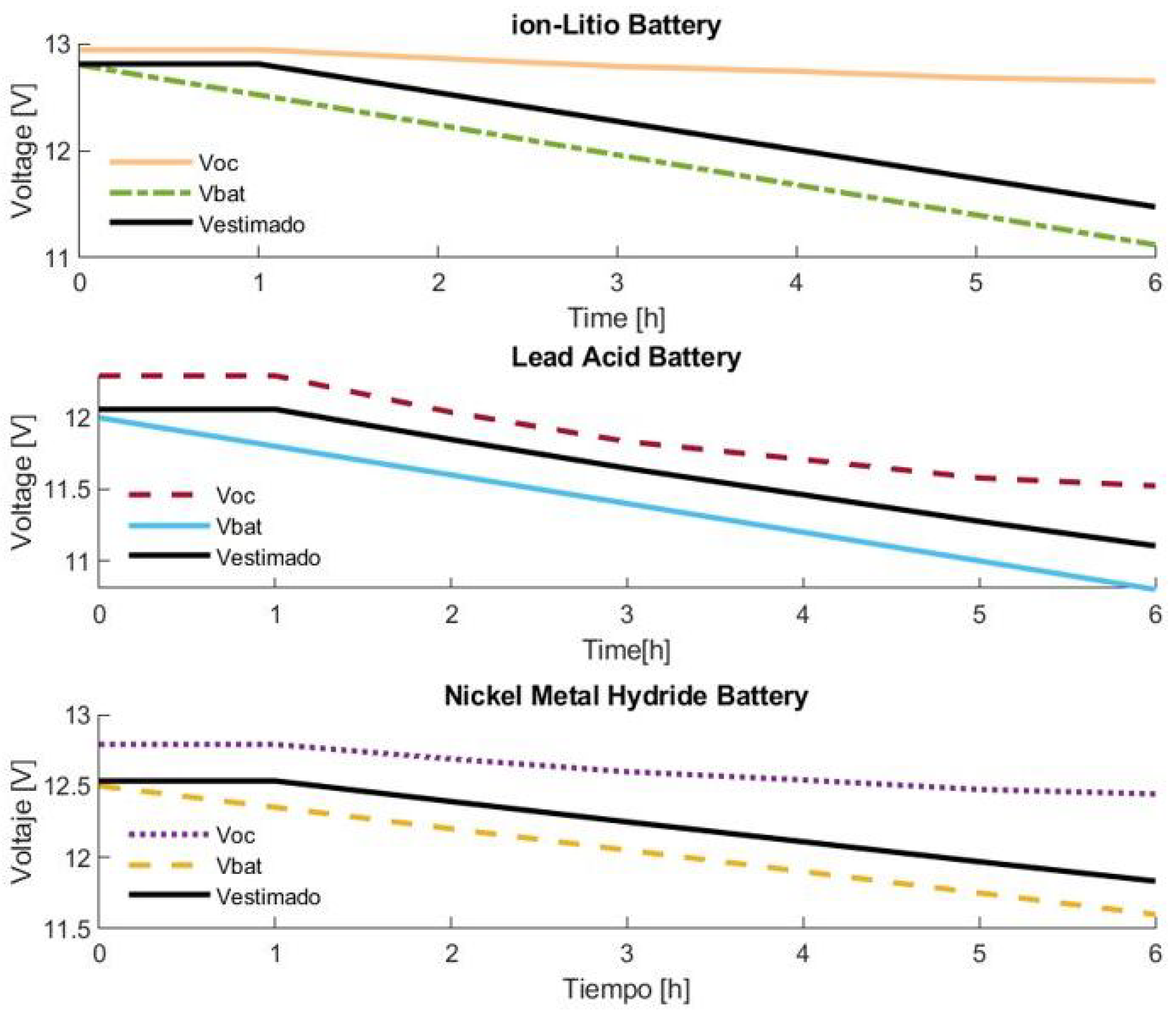
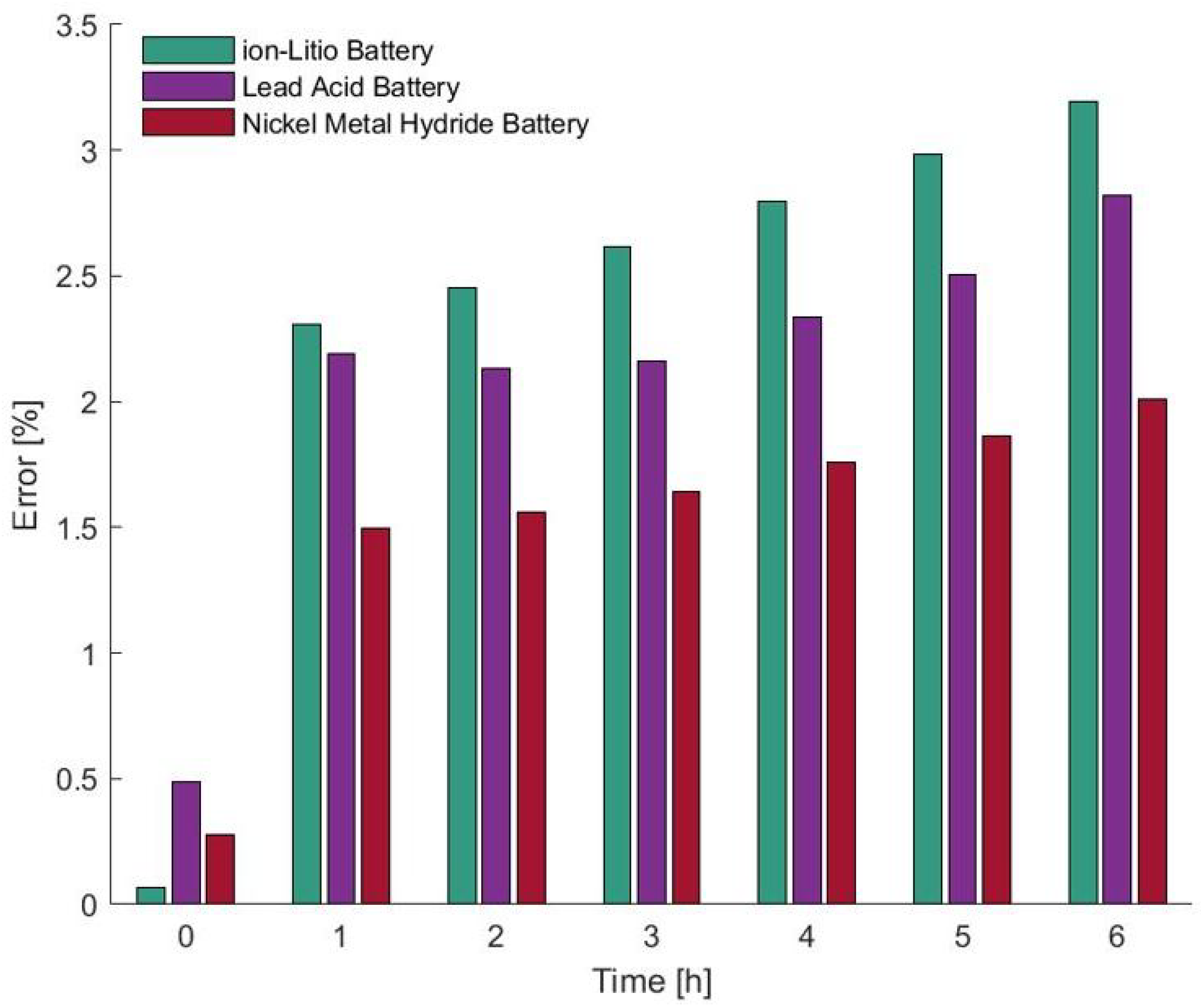
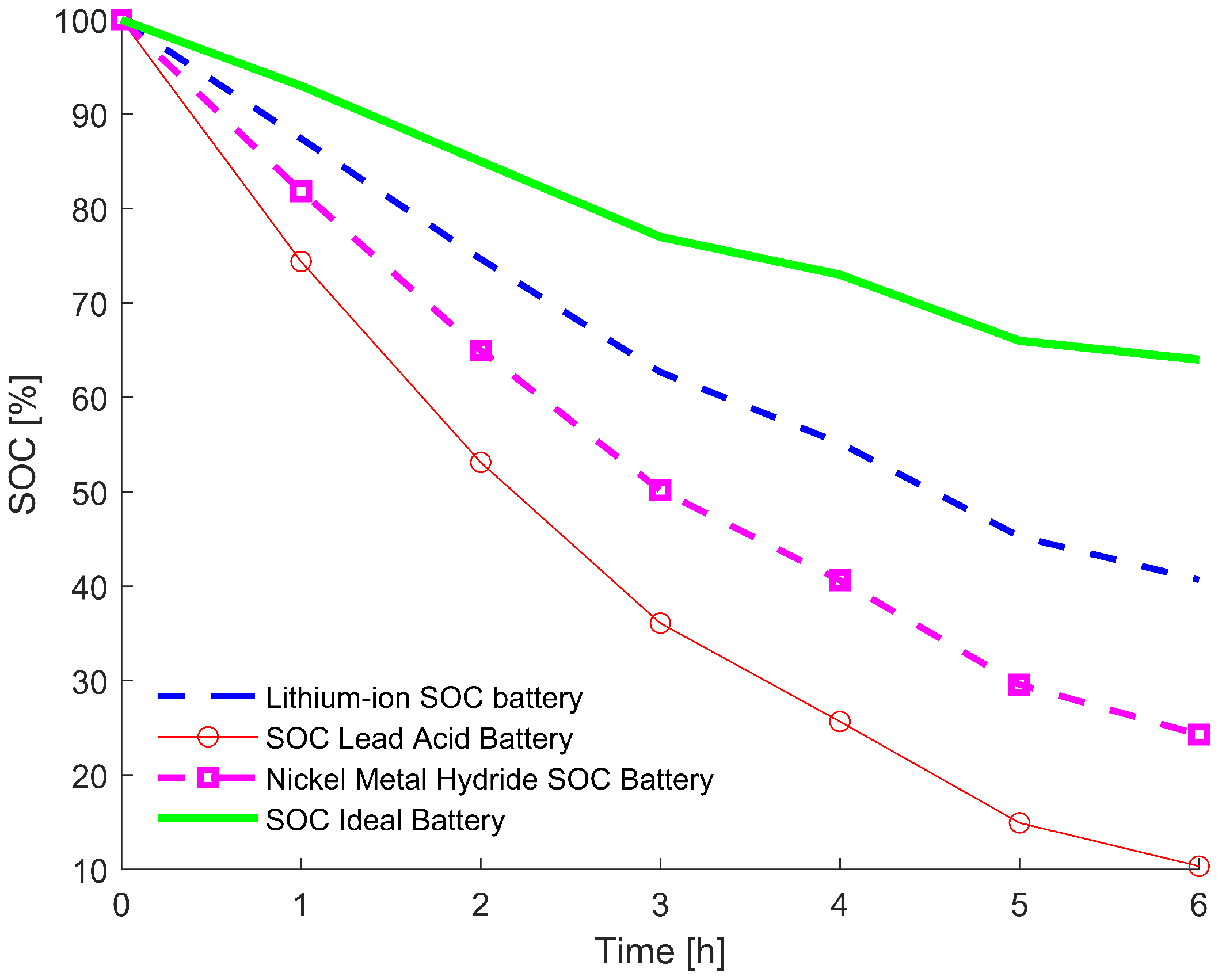
4.1. Discharge
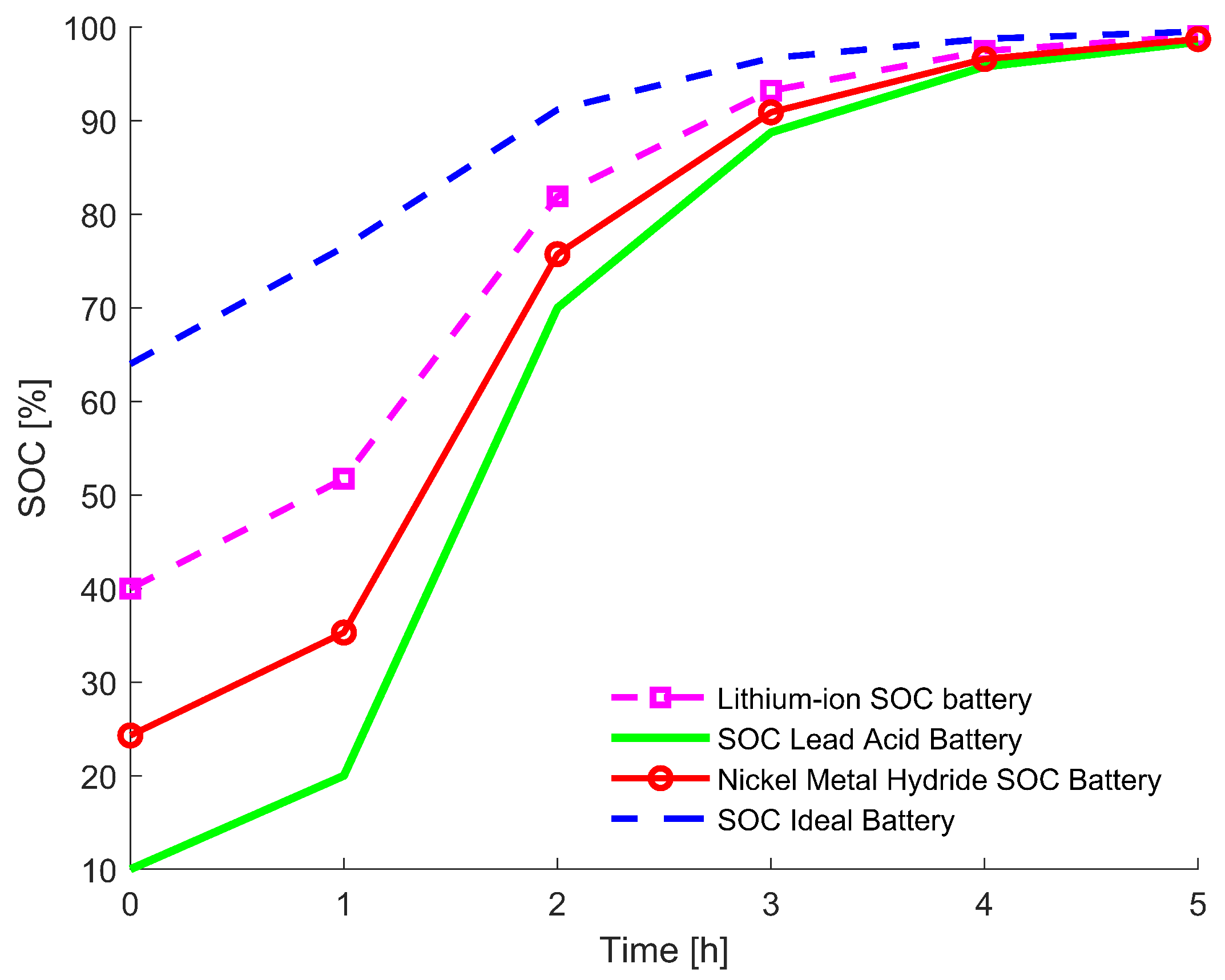
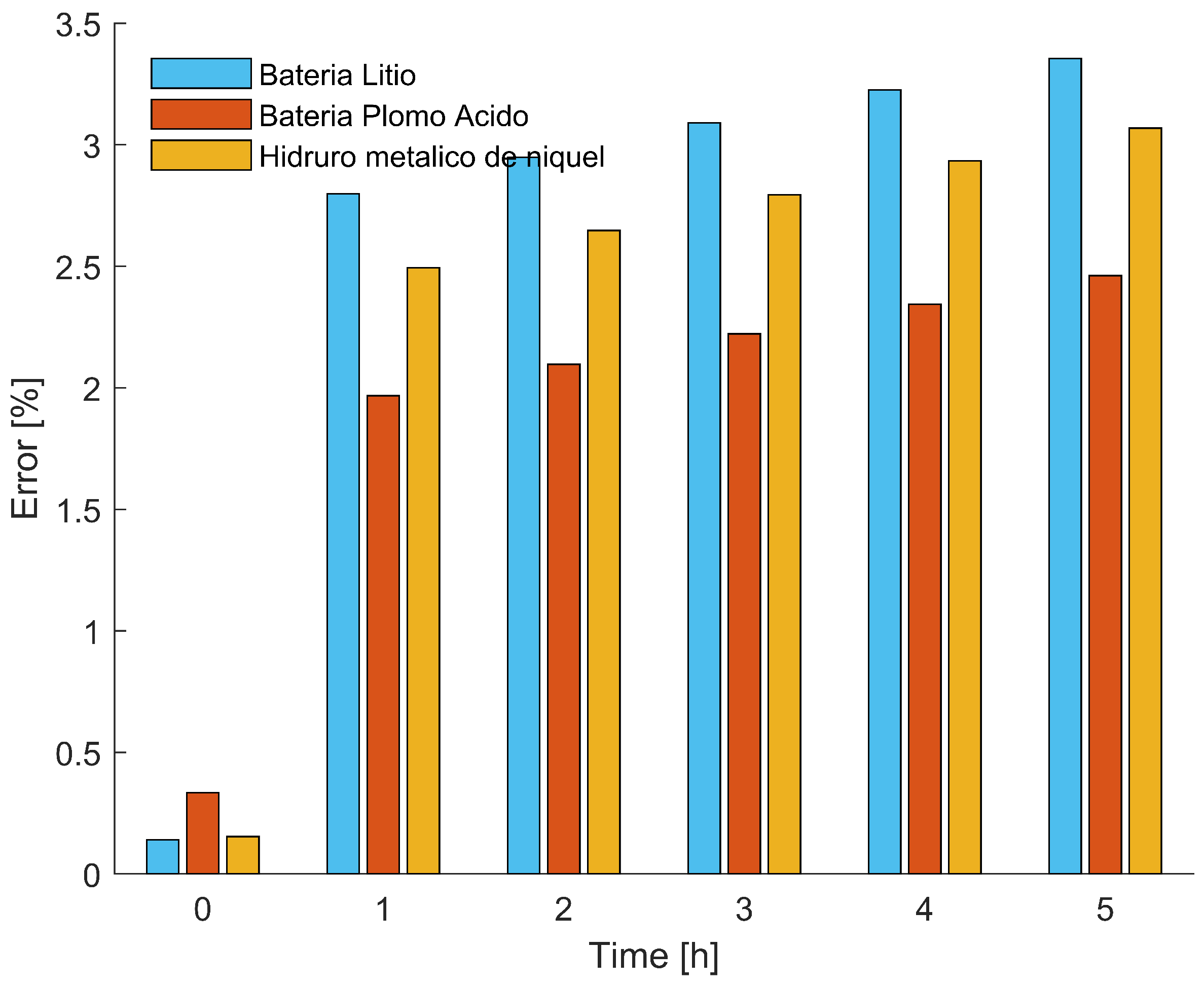
4.2. Charge
5. Conclusions
Author Contributions
Funding
Data Availability Statement
Conflicts of Interest
References
- Sreedhar, V. Plug-In Hybrid Electric Vehicles with Full Performance. In Proceedings of the 2006 IEEE Conference on Electric and Hybrid Vehicles, Pune, India, 18–20 December 2006. [Google Scholar]
- Ruddle, A.R.; Galarza, A.; Sedano, B.; Unanue, I.; Ibarra, I.; Low, I.L. Safety and failure analysis of electrical powertrain for fully electric vehicles and the development of a prognostic health monitoring system. In Proceedings of the IET Hybrid and Electric Vehicles Conference 2013 (HEVC 2013), London, UK, 6–7 November 2013; pp. 1–6. [Google Scholar] [CrossRef]
- Jiang, B.; Liu, Y.; Huang, X.; Prakash, R.R.R. A New Battery Active Balancing Method with Supercapacitor Considering Regeneration Process. In Proceedings of the IECON 2020 46th Annual Conference of the IEEE Industrial Electronics Society, Singapore, 18–21 October 2020; pp. 2364–2369. [Google Scholar] [CrossRef]
- Brandl, M.; Gall, H.; Wenger, M.; Lorentz, V.; Giegerich, M.; Baronti, F.; Fantechi, G.; Fanucci, L.; Roncella, R.; Saletti, R.; et al. Batteries and battery management systems for electric vehicles. In Proceedings of the 2012 Design, Automation & Test in Europe Conference & Exhibition (DATE), Dresden, Germany, 12–16 March 2012; pp. 971–976. [Google Scholar] [CrossRef]
- Ranawat, D.; Prasad, M.P.R. A Review on Electric Vehicles with perspective of Battery Management System. In Proceedings of the 2018 International Conference on Electrical, Electronics, Communication, Computer, and Optimization Techniques (ICEECCOT), Msyuru, India, 14–15 December 2018; pp. 1539–1544. [Google Scholar] [CrossRef]
- Wahyuddin, M.I.; Priambodo, P.S.; Sudibyo, H. State of Charge (SoC) Analysis and Modeling Battery Discharging Parameters. In Proceedings of the 2018 4th International Conference on Science and Technology (ICST), Yogyakarta, Indonesia, 7–8 August 2018; pp. 2–6. [Google Scholar] [CrossRef]
- Zabaleta, J.; San Martín, I.; Pascual, J. Cálculo del Estado de Carga en Baterías de Plomo-ácido: Diseño y Validación Experimental; Universidad Pública de Navarra: Navarra, Spain, 2016; p. 71. [Google Scholar]
- Kiselev, A.; Kuznietsov, A. Motor drive control of a full-electric vehicle using generalized predictive control algorithm. In Proceedings of the 2014 IEEE International Electric Vehicle Conference (IEVC), Florence, Italy, 17–19 December 2014. [Google Scholar] [CrossRef]
- Saleki, A.; Rezazade, S.; Changizian, M. Analysis and simulation of hybrid electric vehicles for sedan vehicle. In Proceedings of the 2017 Iranian Conference on Electrical Engineering (ICEE), Tehran, Iran, 2–4 May 2017; pp. 1412–1416. [Google Scholar] [CrossRef]
- Sabri, M.M.; Danapalasingam, K.; Rahmat, M. A review on hybrid electric vehicles architecture and energy management strategies. Renew. Sustain. Energy Rev. 2016, 53, 1433–1442. [Google Scholar] [CrossRef]
- Susanna, S.; Dewangga, B.R.; Wahyungoro, O.; Cahyadi, A.I. Comparison of simple battery model and thevenin battery model for SOC estimation based on OCV method. In Proceedings of the 2019 International Conference on Information and Communications Technology (ICOIACT), Yogyakarta, Indonesia, 24–25 July 2019; pp. 738–743. [Google Scholar] [CrossRef]
- Zhu, J.; Sun, Z.; Wei, X.; Dai, H. A new lithium-ion battery internal temperature on-line estimate method based on electrochemical impedance spectroscopy measurement. J. Power Sources 2015, 274, 990–1004. [Google Scholar] [CrossRef]
- Saji, D.; Babu, P.S.; Ilango, K. SoC Estimation of Lithium Ion Battery Using Combined Coulomb Counting and Fuzzy Logic Method. In Proceedings of the 2019 4th International Conference on Recent Trends on Electronics, Information, Communication & Technology (RTEICT), Bangalore, India, 17–18 May 2019; pp. 948–952. [Google Scholar] [CrossRef]
- Yu, D.X.; Gao, Y.X. SOC estimation of lithium-ion battery based on Kalman filter algorithm. Appl. Mech. Mater. 2013, 347–350, 1852–1855. [Google Scholar] [CrossRef]
- Gismero, A.; Schaltz, E.; Stroe, D.-I. Recursive State of Charge and State of Health Estimation Method for Lithium-Ion Batteries Based on Coulomb Counting and Open Circuit Voltage. Energies 2020, 13, 1811. [Google Scholar] [CrossRef]
- Giordano, G.; Klass, V.; Behm, M.; Lindbergh, G.; Sjoberg, J. Model-based lithium-ion battery resistance estimation from electric vehicle operating data. IEEE Trans. Veh. Technol. 2018, 67, 3720–3728. [Google Scholar] [CrossRef]
- Hannan, M.A.; Hoque, M.D.M.; Hussain, A.; Yusof, Y.; Ker, A.P.J. State-of-the-Art and Energy Management System of Lithium-Ion Batteries in Electric Vehicle Applications: Issues and Recommendations. IEEE Access 2018, 6, 19362–19378. [Google Scholar] [CrossRef]
- Han, X.; Wang, Z.; Wei, Z. A novel approach for health management online-monitoring of lithium-ion batteries based on model-data fusion. Appl. Energy 2021, 302, 117511. [Google Scholar] [CrossRef]
- Lahsini, M.; Ben Belgacem, Y.; Khaldi, C.; Lamloumi, J. Kinetics and corrosion properties of the LaY2Ni9 alloy used as anode for nickel-metal hydride batteries. In Proceedings of the 2018 9th International Renewable Energy Congress (IREC), Hammamet, Tunisia, 20–22 March 2018; pp. 1–5. [Google Scholar] [CrossRef]
- Zayani, W.; Azizi, S.; El-Nasser, K.S.; Ali, I.O.; Mathlouthi, H. Structural and electrochemical characterization of new co-doped spinel ferrite nanomaterial used as negative electrode in Ni/MH battery. In Proceedings of the 2018 9th International Renewable Energy Congress (IREC), Hammamet, Tunisia, 20–22 March 2018; pp. 1–5. [Google Scholar] [CrossRef]
- Ortiz, J.P.; Valladolid, J.D.; Garcia, C.L.; Novillo, G.; Berrezueta, F. Analysis of machine learning techniques for the intelligent diagnosis of Ni-MH battery cells. In Proceedings of the 2018 IEEE International Autumn Meeting on Power, Electronics and Computing (ROPEC), Ixtapa, Mexico, 14–16 November 2018; pp. 1–6. [Google Scholar] [CrossRef]
- Soltani, M.; Ben Belgacem, Y.; Telmoudi, A.J.; Chaari, A. Parameter identification and state of heath evaluation for Nickel- Metal Hydride batteries based on an improved clustering algorithm. In Proceedings of the 2018 5th International Conference on Control, Decision and Information Technologies (CoDIT), Thessaloniki, Greece, 10–13 April 2018; pp. 128–133. [Google Scholar] [CrossRef]
- Madusanka, S.; Mahadiulwewa, D.; Samarakoon, S.; Sandeepanie, K.; Damayanthi, R. Improving the Performance of Lead Acid Batteries using Nano-Technology. In Proceedings of the 2019 Moratuwa Engineering Research Conference (MERCon), Moratuwa, Sri Lanka, 3–5 July 2019; pp. 589–593. [Google Scholar] [CrossRef]
- Caruso, M.; Castiglia, V.; Miceli, R.; Nevoloso, C.; Romano, P.; Schettino, G.; Viola, F.; Insinga, M.; Moncada, A.; Oliveri, R.; et al. Nanostructured lead acid battery for electric vehicles applications. In Proceedings of the 2017 International Conference of Electrical and Electronic Technologies for Automotive, Turin, Italy, 15–16 June 2017. [Google Scholar] [CrossRef]
- Rosewater, D.M.; Copp, D.A.; Nguyen, T.A.; Byrne, R.H.; Santoso, S. Battery Energy Storage Models for Optimal Control. IEEE Access 2019, 7, 178357–178391. [Google Scholar] [CrossRef]
- Liu, X.L.; Cheng, Z.M.; Yi, F.Y.; Qiu, T.Y. SOC calculation method based on extended Kalman filter of power battery for electric vehicle. In Proceedings of the 2017 12th International Conference on Intelligent Systems and Knowledge Engineering (ISKE), Nanjing, China, 24–26 November 2017. [Google Scholar] [CrossRef]
- Guo, L.; Hu, C.; Li, G. The SOC estimation of battery based on the method of improved Ampere-hour and Kalman filter. In Proceedings of the 2015 IEEE 10th Conference on Industrial Electronics and Applications (ICIEA), Auckland, New Zealand, 15–17 June 2015; pp. 1458–1460. [Google Scholar] [CrossRef]
- Coleman, M.; Lee, C.K.; Zhu, C.; Hurley, W.G. State-of-charge determination from EMF voltage estimation: Using impedance, terminal voltage, and current for lead-acid and lithium-ion batteries. IEEE Trans. Ind. Electron. 2007, 54, 2550–2557. [Google Scholar] [CrossRef]
- Montenegro, D.; Rodríguez, S.; Fuelagán, J.R.; Jiménez, J.B. An Estimation Method of State of Charge and Lifetime for Lead-Acid Batteries in Smart Grid. In Proceedings of the 2015 IEEE PES Innovative Smart Grid Technologies Latin America (ISGT LATAM), Montevideo, Uruguay, 5–7 October 2015; pp. 564–569. [Google Scholar]
- Al Mahmud, A.; Jafar, I.B.; Zaman, A.; Rahman, M. Performance study of lead-acid battery in a solar car under different traffic and weather conditions. In Proceedings of the 2016 4th International Conference on the Development in the in Renewable Energy Technology (ICDRET), Dhaka, Bangladesh, 7–9 January 2016; pp. 21–24. [Google Scholar] [CrossRef]
- Dos Santos, G.S.; Grandinetti, F.J.; Alves, R.A.R.; de Queiróz Lamas, W. Design and simulation of an energy storage system with batteries lead acid and lithium-ion for an electric vehicle: Battery vs. conduction cycle efficiency analysis. IEEE Lat. Am. Trans. 2020, 18, 1345–1352. [Google Scholar] [CrossRef]
- Wang, W. The electrochemical characteristics of AB4-type rare earth–Mg–Ni-based superlattice structure hydrogen storage alloys for nickel metal hydride battery. J. Magnes. Alloy. 2021, 9, 2039–2048. [Google Scholar] [CrossRef]


Publisher’s Note: MDPI stays neutral with regard to jurisdictional claims in published maps and institutional affiliations. |
© 2022 by the authors. Licensee MDPI, Basel, Switzerland. This article is an open access article distributed under the terms and conditions of the Creative Commons Attribution (CC BY) license (https://creativecommons.org/licenses/by/4.0/).
Share and Cite
Salazar, D.; Garcia, M. Estimation and Comparison of SOC in Batteries Used in Electromobility Using the Thevenin Model and Coulomb Ampere Counting. Energies 2022, 15, 7204. https://doi.org/10.3390/en15197204
Salazar D, Garcia M. Estimation and Comparison of SOC in Batteries Used in Electromobility Using the Thevenin Model and Coulomb Ampere Counting. Energies. 2022; 15(19):7204. https://doi.org/10.3390/en15197204
Chicago/Turabian StyleSalazar, Diego, and Marcelo Garcia. 2022. "Estimation and Comparison of SOC in Batteries Used in Electromobility Using the Thevenin Model and Coulomb Ampere Counting" Energies 15, no. 19: 7204. https://doi.org/10.3390/en15197204
APA StyleSalazar, D., & Garcia, M. (2022). Estimation and Comparison of SOC in Batteries Used in Electromobility Using the Thevenin Model and Coulomb Ampere Counting. Energies, 15(19), 7204. https://doi.org/10.3390/en15197204