Review

Tri-Reforming of Methane: Thermodynamics, Operating Conditions, Reactor Technology and Efficiency Evaluation—A Review

1
K1-MET GmbH, Stahlstraße 14, 4020 Linz, Austria
2
Chair of Process Technology and Industrial Environmental Protection, Montanuniversität Leoben, Franz-Josef-Str. 18, A-8700 Leoben, Austria
*
Author to whom correspondence should be addressed.
Energies 2022, 15(19), 7159; https://doi.org/10.3390/en15197159
Submission received: 24 August 2022 / Revised: 19 September 2022 / Accepted: 20 September 2022 / Published: 28 September 2022
(This article belongs to the Section B3: Carbon Emission and Utilization)

Abstract

:
The production of syngas with optimal energy usage, a minimal environmental impact, and an adjustable H2/CO molar ratio is possible using tri-reforming of methane (TRM). Despite the number of studies dedicated to the TRM process, this process is still in its infancy, with many technical obstacles to overcome. Except for its kinetics and catalysts, which have been reviewed elsewhere, the TRM process is evaluated thoroughly in this work. First, feasibility studies of TRM and the TRM process are presented. Second, the impacts of various operating conditions on the rate of gas conversions, syngas production, and coke formation are discussed. Third, different reactor configurations are compared. This review then goes through the energy and energetic efficiency, economic, environmental, and safety aspects of the TRM process. Finally, a research path for the future is suggested.

1. Introduction

Year after year, the world’s energy consumption rises, and fossil fuels account for most of it [1]. This significantly contributes to the increased atmospheric level of CO2, which leads to global warming and climate change [2]. As a result, reducing CO2 levels in the atmosphere is critical. Furthermore, the challenges of implementing alternative energy sources on a broad scale, such as renewables, necessitate a thorough examination of more efficient and clean methods for utilizing fossil energy while reducing greenhouse gas emissions. According to Goeppert et al., converting CO2 to fuels, particularly methanol, is a very successful technique for combating both climate change and fossil fuel depletion [3]. In this regard, an innovative process known as tri-reforming of methane (TRM) was firstly proposed by Song and Pan [4]. With this technique, CO2 obtained from industrial flue gases is converted into syngas without pre-separation [5,6,7]. Therefore, it is possible to reduce the carbon footprint of industrial processes to combat global warming while maintaining economic strength compared to the classic steam reforming of methane (SRM) [8].
According to Equations (1)–(3), this process consists of three primary reactions of methane with carbon dioxide (dry reforming of methane (DRM)), steam (steam reforming of methane (SRM)), and oxygen (partial oxidation of methane (POX)), which occur simultaneously in a catalytic reactor [9,10]:
CH 4 + CO 2     2 CO + 2 H 2             Δ H 298 0 = 247.3   kJ mol               DRM ,
CH 4 + H 2 O     CO + 3 H 2               Δ H 298   0 = 206.3   kJ mol               SRM ,
CH 4 + 1 2 O 2     CO + 2 H 2             Δ H 298 0 = 35.6   kJ mol             POX ,
The advantages of this combined reforming include the high economic benefit of steam reforming, the high energy efficiency of partial oxidation, and the environmental benefit of carbon dioxide reforming [11,12,13]. Furthermore, owing to the presence of O2 and H2O, the carbon deposition on catalyst surfaces is drastically eliminated, resulting in an extended catalyst lifetime [8,14,15]. Another advantage of TRM is the ability to change the relative volume of H2O, O2, and CO2 to effectively regulate the H2/CO ratio of products and avoid the large energy consumption associated with CO2 separation [8,10]. As a result, power plant flue gases containing CO2, H2O, and O2 can be utilized without pre-separation to be converted into syngas [14], and then this syngas may be utilized to generate compounds such as methanol, dimethyl ether, and clean energy sources such as liquid hydrocarbons [16,17,18].
Because of the stability of the reactant molecules, TRM is usually carried out at high temperature (approx. 700–900 °C) and low pressure (atmospheric pressure), as will be explained in Section 5 [19,20].
In addition to Equations (1)–(3), in TRM processes a wide range of endothermic and exothermic side reactions, such as water–gas shift reaction (WGSR), reverse water–gas shift reaction (RWGSR), and methane cracking (Equations (4)–(6), respectively) [21] may occur.
CO + H 2 O     CO 2 + H 2           Δ H 298 0 = 41   kJ mol                                                     WGSR ,
H 2 + CO 2     CO + H 2 O             Δ H 298 0 = + 41   kJ mol                                                 RWGSR ,
CH 4     2 H 2 + C ( s )                                     Δ H 298 0 = + 75   kJ mol               Methane   cracking ,
Moreover, the TRM technique requires a catalyst to guide the reaction’s kinetics and selectivity [22].

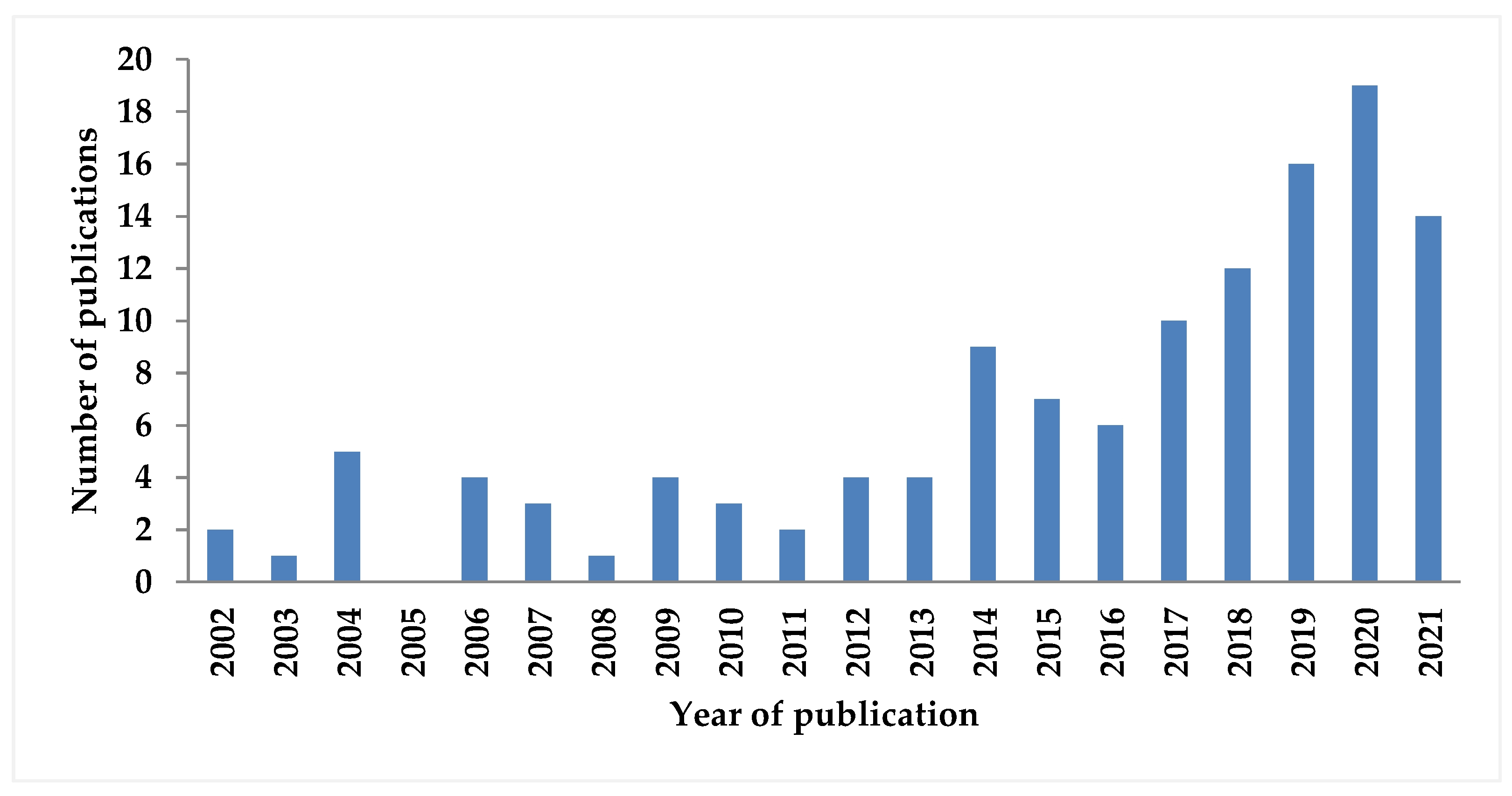
2. Scope of the Current Review

The number of works dedicated to TRM has increased in the last decade. A search on Web of Science found around 130 publications from the year 2002 up to the year 2022, using the keywords “tri-reforming” and “methane”, excluding biogas reforming (Figure 1). However, the focus of this review is on the issues of tri-reforming, which have not been surveyed before. These include the feasibility of TRM, descriptions of the TRM process, the impact of different operating conditions, sensitivity analysis, evaluation of reactor technology, energy and exergetic approaches, and the economic, environmental, safety, and efficiency evaluations of the TRM process.
The work of Minh et al. [23] is dedicated to the reaction mechanisms and catalyst deactivation and regeneration. If the design of TRM catalysts is being examined, the review by Pham et al. [24] can be studied. Amin et al. also looked into TRM from the standpoint of its method, catalysts, and kinetic mechanisms [25]. Process intensification, modeling and simulation, synthesis of catalysts with high-temperature criteria and related process corrosive conditions, and CO2 emission control were also reviewed by Arab Aboosadi and Farhadi Yadecoury [26]. Furthermore, Soloviev et al. provide a thorough analysis of structured nickel–alumina catalysts [27]. Furthermore, the use of biogas as a raw material for the production of synthesized gas through tri-reforming has already been investigated [26,28].

3. Feasibility Studies

In addition to some theoretical calculations [30,31], some experimental studies demonstrate that TRM is feasible [4,32]. Experimental investigations have been carried out using both pure gases and flue gases of power plants for CO2 conversion. Furthermore, since 2008, Korea Gas Company (KOGAS) has incorporated TRM technology into a DME process that can produce syngas with proper control of the H2/CO ratio with minimal coke formation [33]. Nevertheless, these studies are in their early stages and there are still several essential technical challenges to address such as configuration of effective catalysts for industrial applications, finding the proper processing conditions and feed compositions for a desirable ratio of products, inert gas (N2) management, design of reactor and process, process integration into present plants, heat and energy management, and efficient use of heat dissipation. Moreover, all-encompassing economic assessments and consideration of chemicals and fuel mixtures that meet the demands of the market and that can potentially expand them should be considered. As a result, these aspects require thorough research and engineering assessments to develop and implement this innovative process concept [34,35].

4. TRM Process

As mentioned before, flue gas from industries or power plants can be utilized as a co-reactant in the TRM process to produce syngas [36]. Flue gases are mostly composed of CO2, N2, O2, H2O, CO, H2, and trace amounts of NOX and SOX [8]. Because of the huge amount of N2 in flue gas, the conversion will be reduced, resulting in more harmful NOX output. As a result, to remove N2 from the flue gas, an N2 separation unit such as a nitrogen-selective membrane should be used [37,38] or the TRM process can be coupled to an upstream oxy-fuel combustion power plant to alleviate the negative impact of N2 in flue gas from a traditional air–fuel combustion power plant [39].
Input natural gas must also undergo feed pre-treatment, which are desulfurization and pre-reforming processes. Desulfurization occurs when H2 reacts with sulfur molecules in the feed to generate H2S, which is then removed from the primary process. This avoids catalyst poisoning in the main reactor and extends the time between catalyst replacements [40,41]. However, if natural gas which meets the pipeline specifications is used [42], the sulfur contents are negligible [41]. In the pre-reforming section, C2+ hydrocarbons are removed by steam to prevent soot generation and deposition in the main reactor [10,41]. In pre-reforming, the catalyst is mostly the same as in the TRM reactor [41].
As illustrated in Figure 2, to pre-reform the gas, the desulfurized natural gas is mixed with steam and heated up to 550 °C by a multi-pass fired-heater. The pre-reformed gas then mixes with CO2 or flue gas and passes through the fired heater a second time to reach 650 °C before being transferred to the TRM reactor. The oxygen is likewise pre-heated to 650 °C before being delivered to the TRM reactor [10,41]. The TRM reactor’s temperature is kept between 950 and 1000 °C [10,43]. Typically, the TRM reactor is working in an adiabatic catalytic system and is packed with commercial Ni-catalysts (e.g., Ni/Al2O3) [41]. The outlet of the reformer, which contains synthetic gas, unreacted methane, carbon dioxide and steam, is cooled to 25 °C and compressed to 35 bar to separate water [8,44].
After that, unconverted reactants are separated, recycled, mixed with the make-up stream, and fed back into the reactor at the product purification step [10,40]. The processed syngas is then compressed to a pressure of 50 bar and heated up to 220 °C if it enters a methanol reactor [44]. Given that most gas-to-liquid operations, including Fischer–Tropsch, methanol, and DME syntheses, are all carried out at pressures higher than 10 bar, it is more economical to implement TRM reactions at pressures consistent with the downstream processes [37]. Furthermore, water electrolysis [39,41,44,45] and cryogenic air separation units [45] are two common ways to supplement the TRM process with additional oxygen requirements.

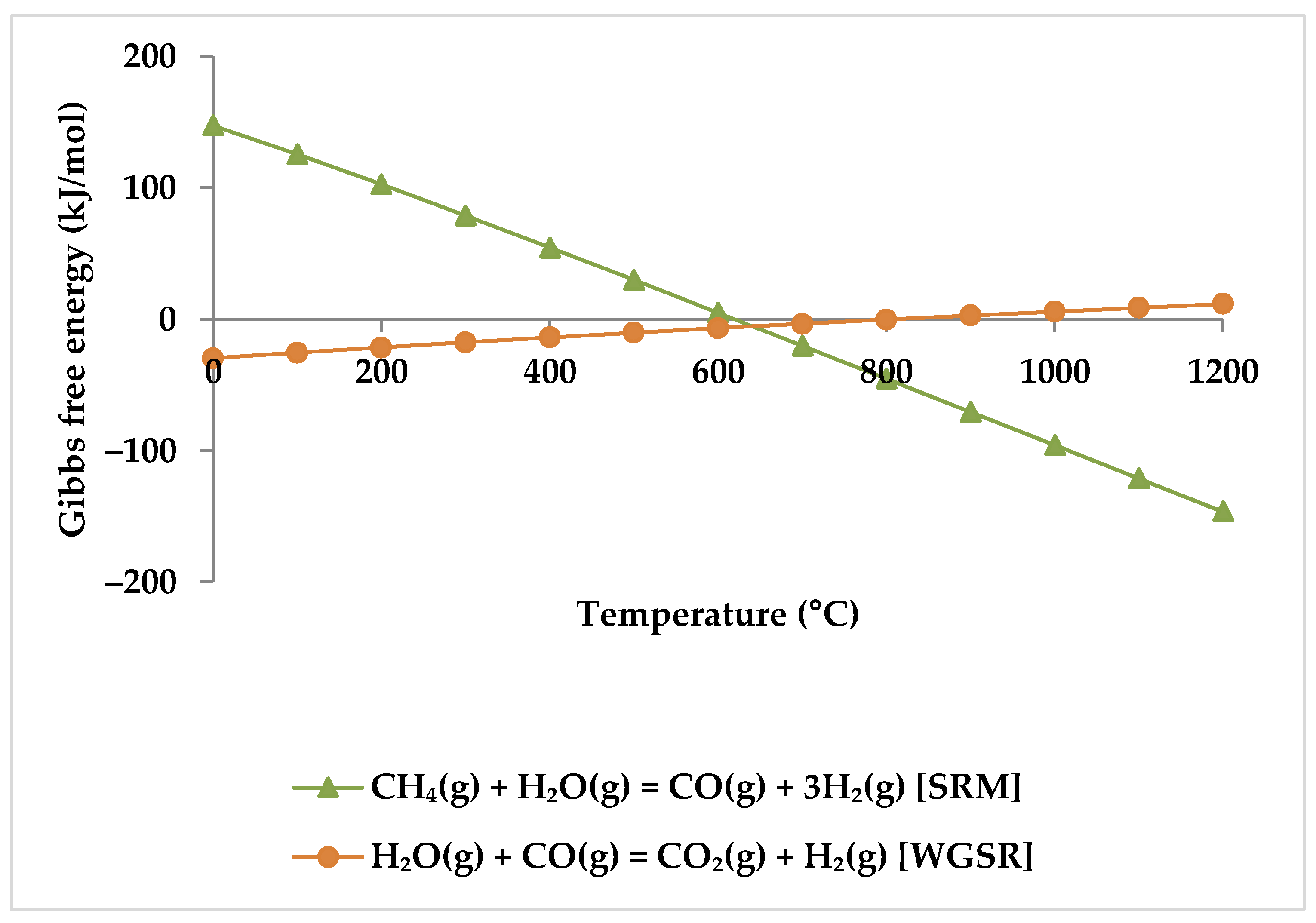
5. Thermodynamic Analysis

This section discusses the effect of various operational parameters on feed gas conversions and H2/CO ratios.

5.1. Effect of Temperature

Generally, the reaction kinetics improve as the temperature rises; therefore, the reactor volume required for the same conversion decreases [46]. Ren et al. found that when the temperature grew from 400 to 800 °C at 1 atm, the conversion of CH4, CO2, and H2O increased significantly. However, a further increase in temperature led to a gradual increase in the conversion of the reactants, reaching close to 100% at 1000 °C [47,48]. When one compares Ren et al.’s experimental results with the results of ASPEN plus simulation (Figure 3) under the same condition, their findings are in conformity with the model. Table 1 shows this simulation specification. The reason for higher conversions at higher temperatures is that the DRM and SRM prevail at higher reaction temperatures due to their endothermic character (Equations (1) and (2)) [4,47,49,50].
While the overall reaction enthalpy at lower temperatures up to 400 °C remains modestly exothermic, endothermicity grows rapidly as temperature rises [51]. According to Figure 4, methane oxidation reactions and WGSR, which are exothermic with negative Gibbs energy below 400 °C, are a reasonable source of the exothermicity of this process.
Depending on thermodynamics, a temperature of at least 650 °C is necessary for effective reactant conversion in methane reforming [19,49,51,52]. Moreover, at temperatures below 550 °C, the phenomena of negative CO2 conversion can be observed due to WGSR (Equation (4) and Figure 5) [48], while at temperatures above 600 °C, RWGSR (Equation (5), Figure 5) accompanies the DRM reaction to consume CO2 [51].
Regarding the products, increasing the temperature causes a rise in the CO mole fraction from zero at 400 °C to the maximum at about 850 °C. Meanwhile, the mole fraction of CO2 starts to decrease and reaches zero at 850 °C. This suggests that CO2 acts in the reactions as a limiting reagent. With increasing temperature, the molar fraction of H2 continues to rise while the molar fraction of CH4 continues to decrease, which confirms that there is a direct relationship between H2 production and CH4 consumption. Therefore, it is clear from the TRM reactions that the CH4 intake is the main H2 production source [53]. Following Zhang et al., the reason for H2 production at temperatures below 400 °C is methane cracking (Equation (6)) [53]. However, this hypothesis is questionable because this reaction has positive Gibbs free energy at this temperature range (Figure 6). For the production of H2, the POX reaction (Equation (3)), which has a negative Gibbs energy in all temperature ranges, appears to be the cause. WGSR is also likely to occur alongside the POX reaction to produce H2 but with a lower probability (Figure 6).
Lower reaction temperatures have a significant impact on the H2/CO molar ratios. The H2/CO molar ratio might drop dramatically, for instance, from 11.8 to 2.1, when the temperature rises from 400 to 600 °C, regardless of the feed molar ratios. Further raising the reaction temperature to 1000 °C results in a slight decrease in H2/CO molar ratio (for example, around 2.0), which is influenced by the composition of CH4, CO2, H2O, and O2 [4,47,52,54,55]. The reason is that above 650 °C, the RWGSR is predominant and consumes more H2 and produces CO. In addition, the conversion of CO2 improves; thus, it lowers the ratio of H2/CO [19,50].
Based on the findings stated above, a high temperature along with low pressure is desirable to achieve high CO2 conversion and H2 yields. However, more energy demand is needed for a higher temperature reaction, which will inevitably increase the cost of the TRM operation, while at low pressures, temperatures above 850 °C do not provide significant benefits regarding the syngas ratio and conversions. Given the above consequences, the ideal reaction temperature is considered to be lower than 850 °C [51,56,57].

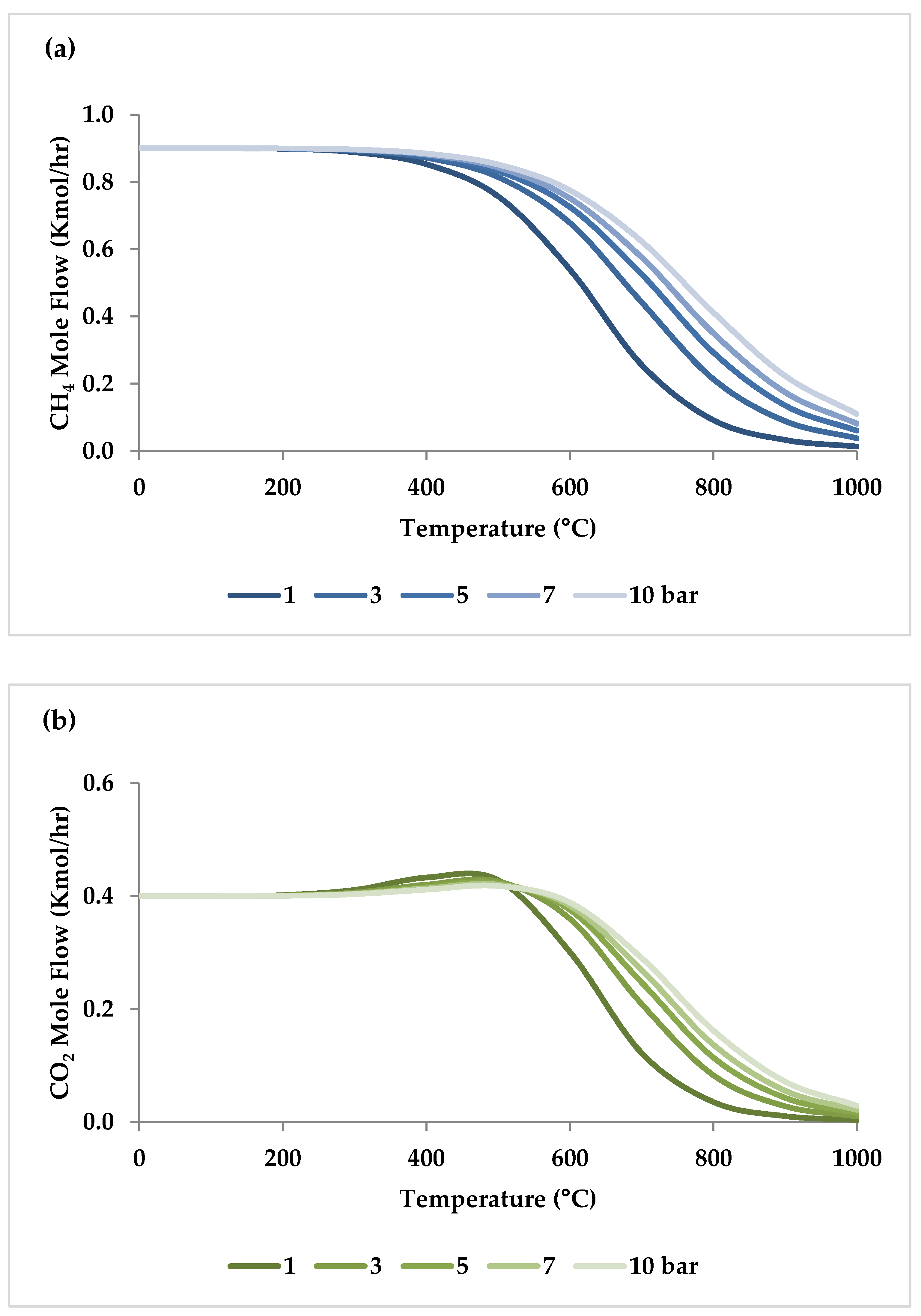
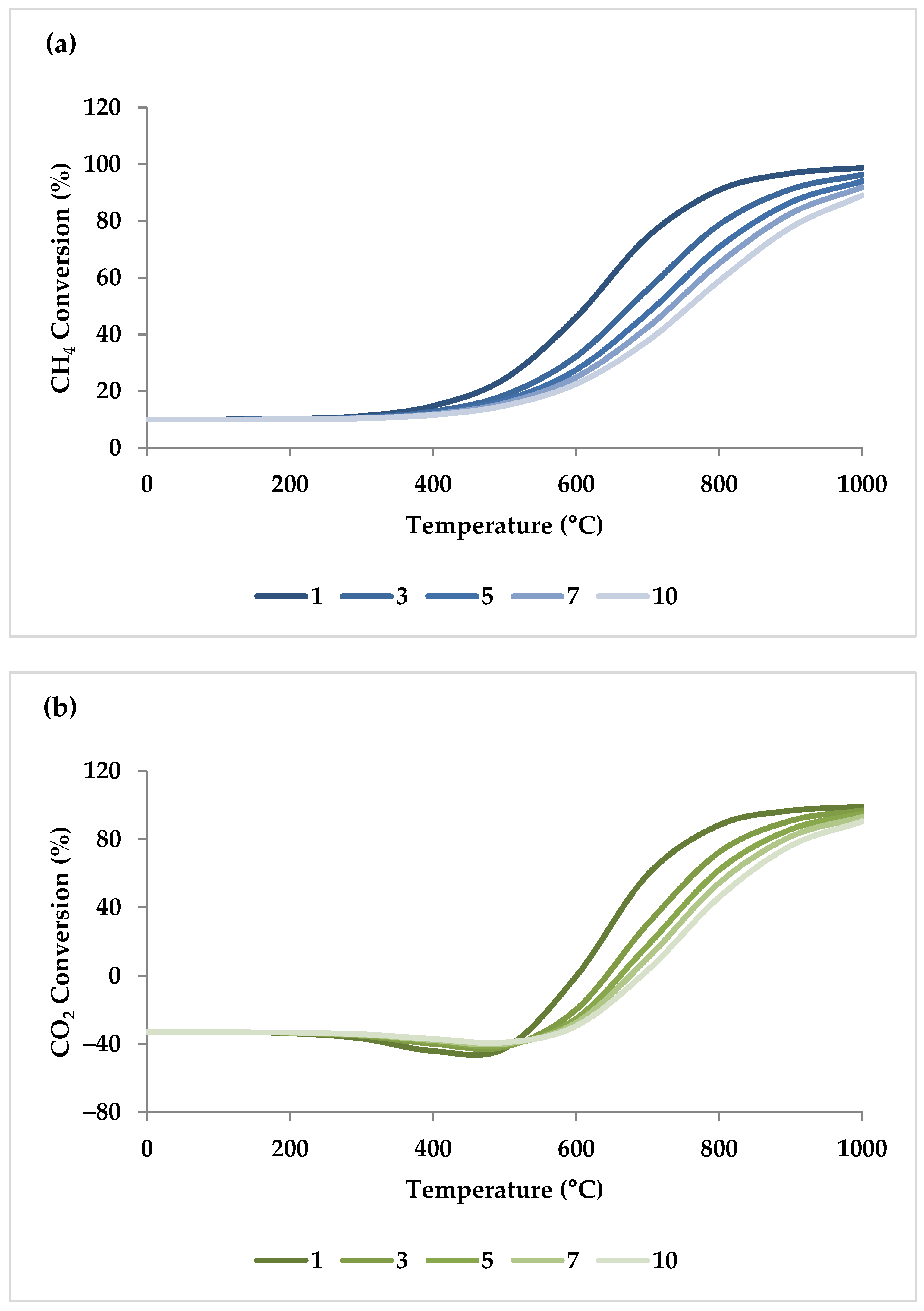
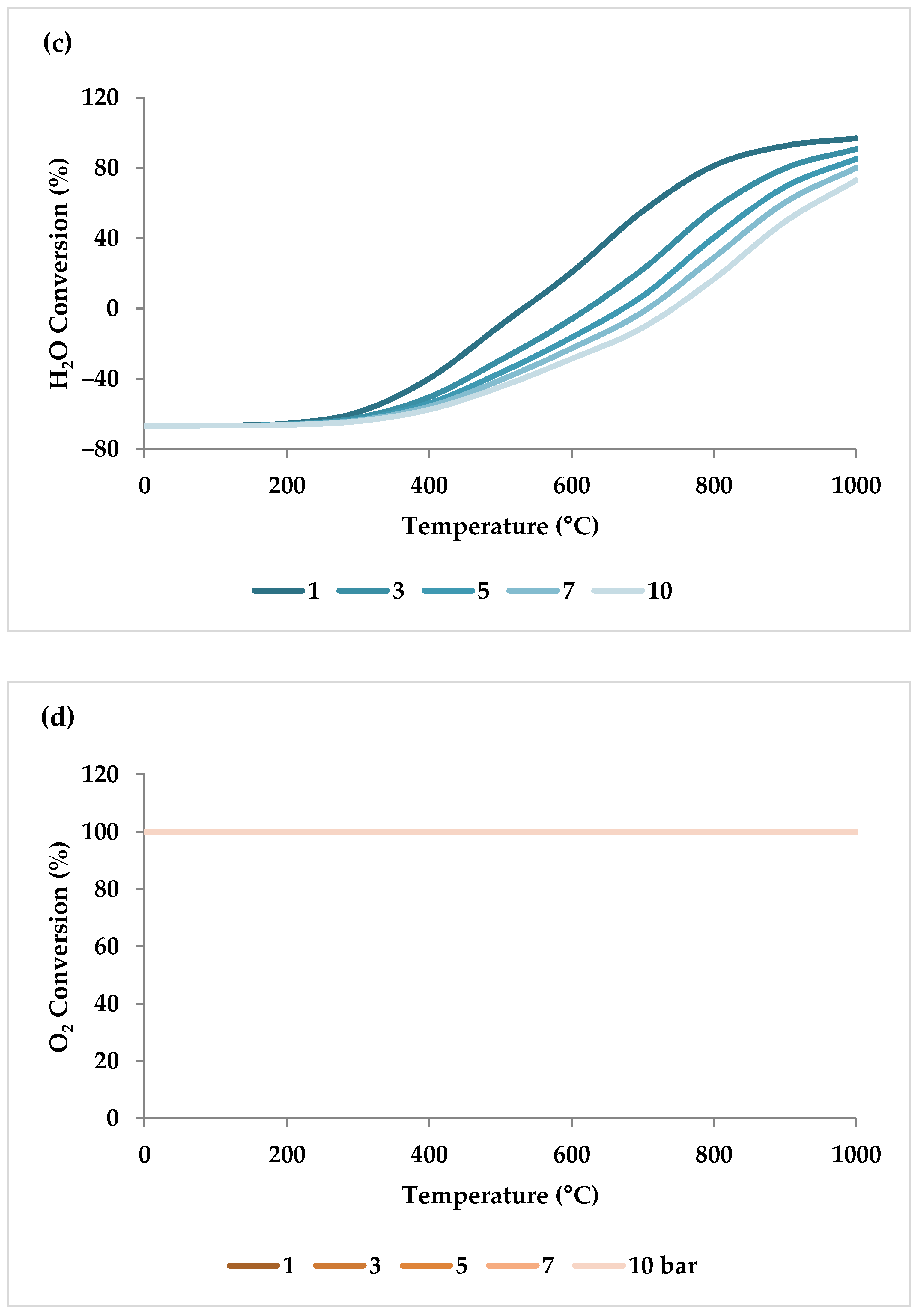
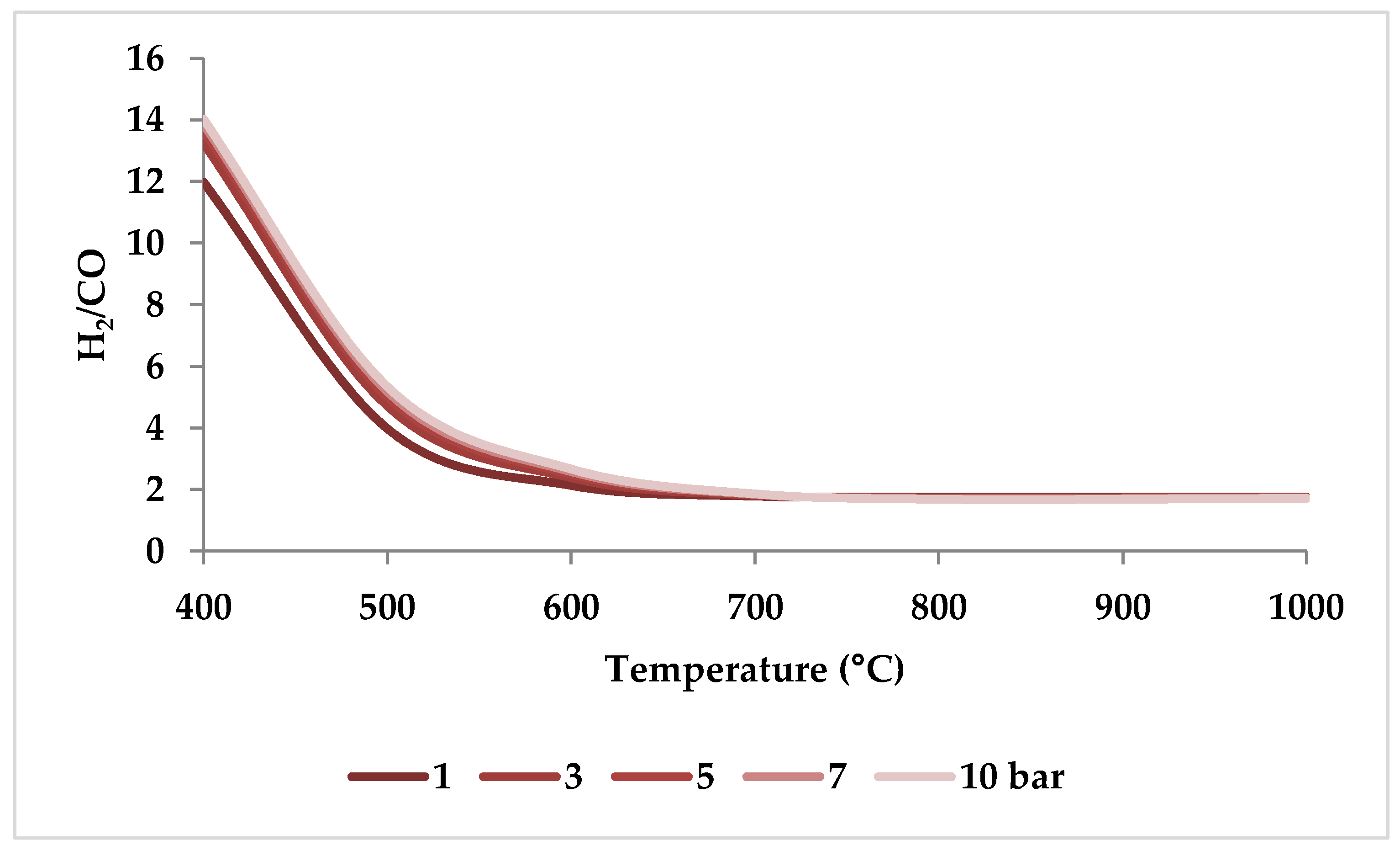
5.2. Effect of Pressure

Pressure is a crucial factor in setting the equilibrium state during TRM and is one of the primary variables that control the mole fractions of products [19]. The application of Le Chatelier’s principle to Equations (1)–(3) demonstrates that synthesis gas output is reduced at higher pressures [20]. Increasing the pressure up to 20 bar contributes to a drop in the H2 mole fraction and an increase in the CH4 mole fraction even at 850 °C. Regarding CO2 and CO, the influence of pressure at temperatures below 450 °C is negligible, which means that DRM is not feasible in this temperature range. If the temperature rises above 450 °C, the rise in pressure leads to continuous growth in the concentration of CO2 and a simultaneous decline in the concentration of CO [47]. Similarly, with increasing pressure, the molar fraction of H2O increases constantly [19]. On the other hand, pressure has a minor influence on O2 conversion [47]. The results of thermodynamic equilibrium concentrations and conversions simulated with ASPEN plus, which are presented in Figure 7 and Figure 8, respectively, also confirm these findings from the literature. The ASPEN plus simulation conditions and settings are presented in Table 2.
Based on the simulation results, and according to the minimum required temperature for O2, CO2, and H2O conversions, one can conclude that the tendency of CH4 to react with other reactants is as follows: O2 > H2O > CO2, which is explainable by their Gibbs free energies (Figure 9).
Figure 10 shows the calculated equilibrium conversions depending on pressure for TRM. This calculation was performed by ASPEN plus and minimized the Gibbs free energy under conditions identical to the experimental conditions used by Ren et al. [47]. It is clear that the conversion of CH4 is higher than that of CO2 and H2O at different pressure values [47]. In addition, in any pressure range, CO2 conversion in TRM is much lower than in DRM, suggesting that the DRM reaction is hindered when O2 and/or H2O are present in the reaction environment [47,51].
When raising the pressure from 1 to 20 bar, the H2/CO molar ratio increases with pressure up to 800 °C and then drops slightly to reach a steady value (i.e., 1.5), demonstrating that pressure has a more limited role in regulating H2/CO molar ratios at higher temperatures [51]. This trend can be verified by ASPEN plus simulation as depicted in Figure 11 (the settings of simulation are according to Table 2). This observation is consistent with the study by Ren et al., which demonstrated that at 750 °C, the decrease in H2/CO ratio was very small with increasing pressure (Figure 10) [47].
In conclusion, relatively low pressures are optimal for CO- and H2-rich production and CO2 conversion optimization [19,20,53,55]. However, the effect of pressure on conversions and product ratio is marginal when the temperature is higher than 1000 °C [47,51].

5.3. Effect of CH4/Flue Gas Ratio

Since CH4 reacts with all the active agents (CO2, O2, and H2O), the CH4/flue gas ratio has a noteworthy role in TRM reactions, especially in the formation of CO and H2. However, the effect of the reaction temperature has to be considered in parallel. When the temperature is below 850 °C, higher CH4/flue gas ratios increase the molar flow rate of H2. For temperatures above 850 °C, H2 molar flow follows a weak correlation of the CH4/flue gas ratio, and the production of H2 is also maximal under every CH4/flue gas ratio. The CH4/flue gas ratio has a similar effect on CO production as for H2. However, the influence of the CH4/flue gas ratio on the CO2 molar flow is different. A rise in the ratio of CH4/flue gas causes an increase in the molar flow of CO2 at temperatures below 550 °C, while it causes a decrease in the molar flow of CO2 at temperatures higher than 550 °C. When the reaction temperature exceeds 850 °C, the CO2 content approaches zero, if the CH4/flue gas ratio is between 0.4 and 1.0, indicating that CO2 is the limiting reactant that inhibits additional syngas production. Therefore, when the operating temperature is higher than 850 °C, lower CH4/flue gas ratios can be chosen to reduce CH4 consumption [53].

5.4. Effect of O2/CH4 Ratio

By increasing the O2/CH4 ratio, CH4 conversion becomes higher, mainly at temperatures lower than 850 °C, because CH4 is the limiting reactant [19]. However, the rise in the O2/CH4 ratio results in a substantial drop in CO2 conversion across the entire temperature spectrum [19,45,50,58,59] because the reaction between CH4 and O2 is thermodynamically preferred over the reaction between CO2 and CH4 [50,59,60] (Figure 9). The combustion of CH4 (Equation (7)) overtakes the DRM reaction and thereby a net rise in the amount of CO2 is created [50,61]. Similarly, with increasing O2 content, H2O conversion declines [62]. However, the H2O conversion reduces more significantly compared to CO2 conversion [31], which results in a lower H2 yield, and consequently a lower H2/CO ratio [19,31]. In other words, CH4 is likely to be combusted to H2O and CO2 instead of H2 and CO at a comparatively high O2 concentration [19]. Under these conditions, the amount of CH4 available for DRM and SRM is quite limited [61].
CH 4 + 2 O 2     CO 2 + 2 H 2 O         Δ H 298 0 = 803   kJ mol             Full   combustion   of   methane ,
When the O2/CH4 ratio is between 0.45 and 0.50 for varied H2O/CH4 ratios, the input CH4 reacts completely [63]. The complete oxidation of methane releases large amounts of energy that provides heat for endothermic reactions and contributes to the thermal equilibrium of the process [50,60].
However, regarding the effect of the O2/CH4 ratio on the syngas ratio (H2/CO), there are two opposing findings. Some references mention that as the O2/CH4 ratio rises, the syngas ratio drops because the higher O2/CH4 ratio in addition to higher reaction temperatures not only increases DMR but also accelerates the RWGSR, boosting CO generation [55,64]. However, others report that oxygen has the same effect as steam on the H2/CO ratio. Increasing the O2/CH4 ratio results in a higher H2/CO molar ratio because the higher the oxygen content, the less methane is accessible in the reaction environment. As a result, SRM would replace DRM, resulting in a higher H2/CO molar ratio [4,65]. These arguments appear to be inaccurate. In [4], authors changed the other feed gas ratios at the same time as oxygen, and in [64], in addition to using a membrane reactor to disperse O2, the H2/CO ratio was practically constant (1.57 and 1.58). Furthermore, according to Yang et al., the range of the O2/CH4 ratio is essential because when this ratio is between 0.1 and 0.4, the H2 yield is increased by the O2/CH4 ratio, and when the O2/CH4 ratio is greater than 0.4, the H2 yield decreases gradually [63]. The reason is that a high O2/CH4 ratio will result in a hydrogen combustion reaction [64,66]. Thus, the conclusions of references [55,65] contradict the conclusions of Yang et al., as [65] studied a lower range of O2/CH4 ratios (0.01–0.29) and [55] worked in a wider range of O2/CH4 ratios, from 0.2 to 0.75.
In addition, thermodynamic studies have revealed that to achieve high synthesis gas efficiency and avoid coke formation, adiabatic processes require a considerable oxygen input (about half of the methane feed) [64] but for non-adiabatic processes with stable methane reforming, a O2/CH4 ratio of 0.25 is required [67]. It is also evident that increasing the O2 concentration reduces not only the coke formation but also the process’s energy consumption [51]. Moreover, it is also advised to utilize pure oxygen with a low pressure rather than air with a high pressure to decrease its impact on the reactor volume [46].

5.5. Effect of H2O/CH4 Ratio

With a rise in H2O up to a specific concentration at low temperatures, CH4 conversion falls [19,59,68], and it converts to a growing pattern after reaching an inflection point at relatively high temperatures. However, above 850 °C, a conversion of CH4 of almost 100% is obtained, independent of the H2O content [19].
There is clear evidence that the SRM outweighs DRM with increasing H2O concentration [50]. The growth in H2O content causes a substantial reduction in CO2 conversion [59] because, for TRM, CO2 and H2O are both oxidizing agents [37,69], but CH4 is thermodynamically more likely to react with H2O [19,25,65]. Moreover, both SRM and WGSR are preferred at a higher molar ratio of H2O/CH4, which again lowers CO2 conversion [16,46,59,70]. High H2O/CH4 ratios, on the other hand, promote methane conversion. The amount of methane engaged in SRM rises to more than 50% as the H2O/CH4 ratio rises, whereas the DRM falls to 7% [71].
The effect of H2O content on H2O conversion depends on temperature. When the temperature exceeds 650 °C, the H2O conversion rate falls as the H2O/CH4 molar ratio rises. This is due to a lack of CH4 available to react with H2O. Furthermore, above 650 °C, RWGSR also dominates, leading to lower H2O conversion rates and, consequently, lower H2 yields and H2/CO ratios [19]. Nevertheless, the conversion rate of H2O rises with an increase in the H2O/CH4 molar ratio while the temperature is below 650 °C [19]. However, there is no adequate justification for this phenomenon in the literature. For instance, according to Zhang et al. and Singha et al., both WGSR and SRM reactions are equally important below 650 °C [19,59], consuming steam. However, this cannot be the case for SRM because it has a positive Gibbs free energy in this temperature range (Figure 12). Therefore, only WGSR can happen, and an increase in H2O, which favors WGSR, drives this reaction to consume more H2O.
Another point is that increases in feed gas content of H2O can boost H2 yield while decreasing CO yield [19,55,64,65]. Therefore, the H2/CO molar ratio increases as the H2O/CH4 molar ratio increases [18,20,31,33]. However, based on the amount of H2O brought in, the ratio between the DRM and SRM reactions can be influenced, and thus the H2/CO ratio is highly adjustable [50,68]. Moreover, excessive steam might deactivate the catalyst by oxidizing its surface [16]. Furthermore, adding steam, unlike oxygen, increases the required energy of the process [51].

5.6. Effect of CO2/CH4 Ratio

CH4 conversion improves by increasing the CO2/CH4 ratio, while CO2 conversion declines [19,72]. However, the CO2/CH4 ratio has a far smaller impact on the methane conversion than the O2/CH4 ratio [63].
With different CO2/CH4 ratios at low temperatures, the effect of the CO2/CH4 ratio on CO and H2 yields tends to be marginal. However, the H2 yields decrease considerably when CO2 is added at temperatures above 700 °C [19]. The foremost reason is that a higher CO2/CH4 ratio induces RWGSR to consume H2 and produces more CO, leading to a reduction in the H2/CO ratio [19,62,63,73]. Likewise, as the CO2 level climbs, the amount of H2O produced by RWGSR decreases. There is, in fact, a trade-off between maximal CO2 conversion and syngas ratios of 2 or more. In other words, a lower synthesis gas ratio is available for higher CO2 conversion [64].
The ideal CO2/CH4 ratio is 1.43; at lower ratios more methane is available, which cannot react efficiently [66].

5.7. Effect of O2/CO2 Ratio

When the O2/CO2 ratio increases from 0 to 1.5, while the CH4 and H2O molar ratios are constant, the average CO2 conversion drops, for example, from 60 to 33% at atmospheric pressure and 750 °C [52]. The decline in CO2 conversion is due to a higher amount of O2 in the feed, which inhibits DRM and raises methane oxidation. Therefore, the higher O2/CO2 ratio produces syngas that is richer in H2 as a consequence of the reduced CO2 conversion, causing the higher H2/CO ratios [50,52,74].

5.8. Effect of H2O/CO2 Ratio

Raising the H2O/CO2 ratio in the feed stream promotes SRM over DRM, resulting in a rise in the H2/CO ratio, lowering CO2 conversions. For instance, at atmospheric pressure and 750 °C, while the other gas molar ratios are constant, the CO2 conversion falls from 73 to 30% [52,66]. When there is no rivalry between CO2 and H2O for adsorption sites in the absence of water vapor, the maximum CO2 conversion is attained [49].
Table 3 provides a summary of the conclusions from these Section 5.1, Section 5.2, Section 5.3, Section 5.4, Section 5.5, Section 5.6, Section 5.7 and Section 5.8.

6. Optimal Operating Conditions and Feed Compositions

As mentioned previously, TRM is very sensitive to reaction conditions, specifically temperature and feed composition. In the TRM operation, the pressure, temperature, and feed ratios (H2O/CH4, O2/CH4, and CO2/CH4) are independent variables influencing the overall efficiency. These variables affect the thermodynamic equilibrium, the kinetics of the related reactions, and the resulting H2/CO ratio [59]. However, the required energy of the system and CO2 conversion is more sensitive to the feed composition variation rather than temperature. The effect of a 1% fluctuation in operating temperature (considering an industrial setting) on both energy consumption and CO2 conversion is minimal, while a 1% change in feed composition resulted in a nearly 5% increase in both energy demands and CO2 conversion [51].
Regarding the optimum feed composition, several feed ratios have been considered optimum in the literature, which are summarized in Table 4. For example, Zhang et al. discovered that the best feed ratio was CH4:CO2:H2O:O2 = 1:0.291:0.576:0.088, which resulted in a 94.5% H2 yield, with the H2/CO ratio of 2.0 and the CO2 conversion more than 90% [19]. Jarungthammachote observed the best feed ratio as CH4:CO2:H2O:O2 = 1:0.282:0.574:0.1, leading to the H2 yield of 94.94%, H2/CO ratio of 2.0, CO2 and CH4 conversions ≥ 90 [36]. These two groups of researchers used nearly identical feed ratios and obtained almost similar results at the reaction temperature and pressure of 850 °C and 1 atm. On the other hand, Rezaei et al. determined that the optimum feed composition was CH4:CO2:H2O:O2 = 1:0.2:0.35:0.48 to achieve the CO2 conversion of 50% at 30 bar and 1000 °C. They also concluded that the feed should have a CO2/CH4 ratio of 0.1–0.2, an O2/CH4 ratio of 0.4–0.5, and H2O/CH4 ratios of 0.25–0.5 [75]. Moreover, Jarungthammachote observed that as the O2 concentration of the co-reactant increased while the conversions and yields remained high, the optimal CO2/CH4 and H2O/CH4 ratios decreased. However, the maximum H2 yield occurred beyond the optimum CO2/CH4 and H2O/CH4 ratios, where the CO2 conversion was less than 90% [36]. Furthermore, Challiwala et al. discovered that the best working conditions are about 750 °C and 1 bar, with a feed mole ratio of CH4:CO2:H2O:O2 = 1:1:0.4:0.3. Under this condition, the process energy consumption is minimized and the CO2 conversion is 47.84%, while carbon deposition is suppressed. This temperature was chosen as the ideal value since it benefits from both RWGSR and DRM reactions at the same time, whereas at high temperatures of about 900 °C, RWGSR has a detrimental influence on both the energy required for the process and the H2/CO ratio of syngas [51]. The combined effect of low pressure and high temperature is favorable for the TRM process efficiency [55]. However, due to the catalyst strength limits and higher energy consumption, the temperature does not exceed the ceiling value. According to the thermodynamic equilibrium, the maximum temperature and pressure are 850 °C and 1 atm., respectively, to achieve more than 90% CO2 conversion, a H2/CO ratio of equal to 2.0, and to prevent solid carbon formation during reactions [19]. As a result, the appropriate feed composition depends on both the operating parameters of the process and the kind of catalysts utilized. Additionally, the desired condition (energy usage, coke avoidance, etc.) altered these best values.

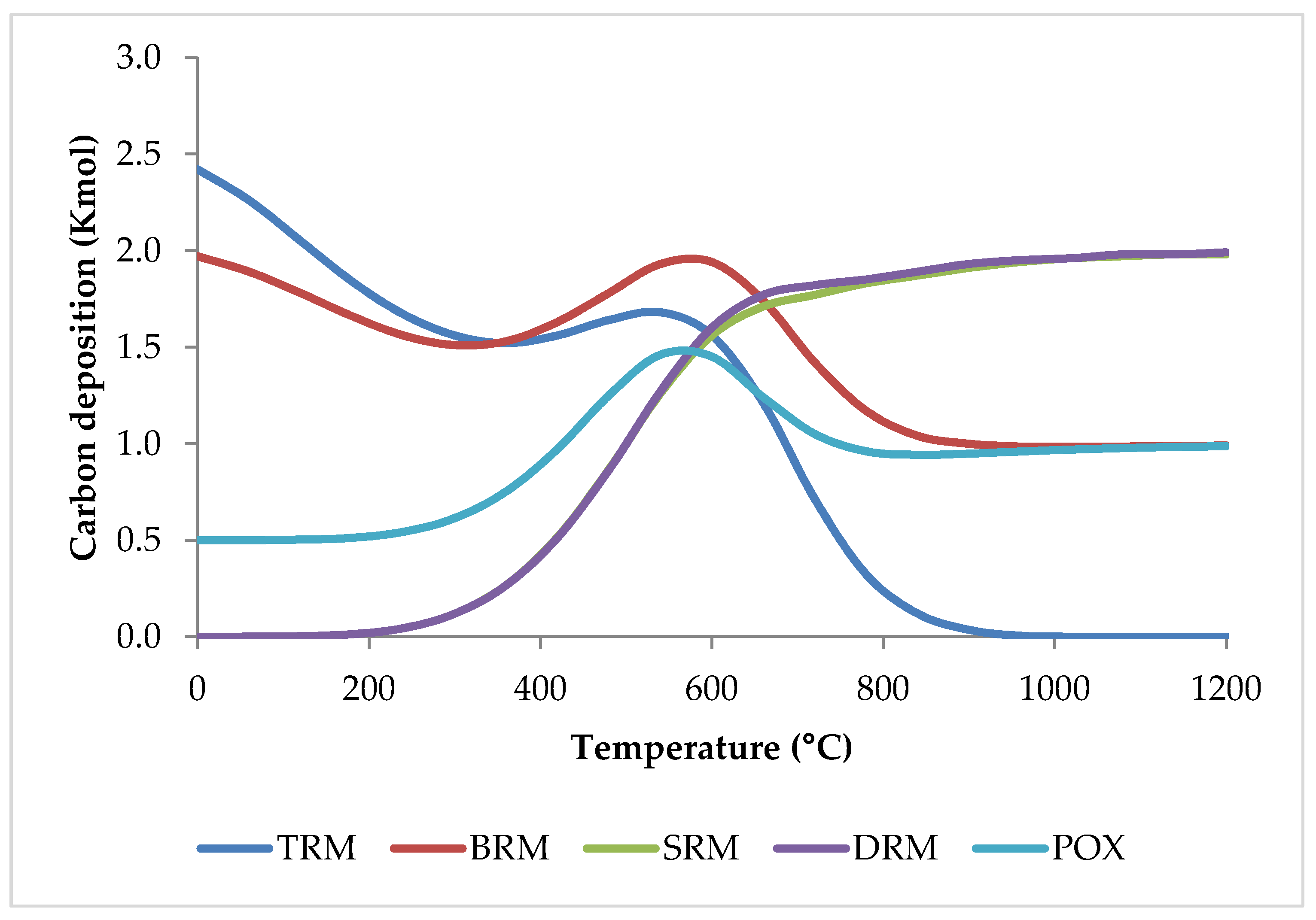
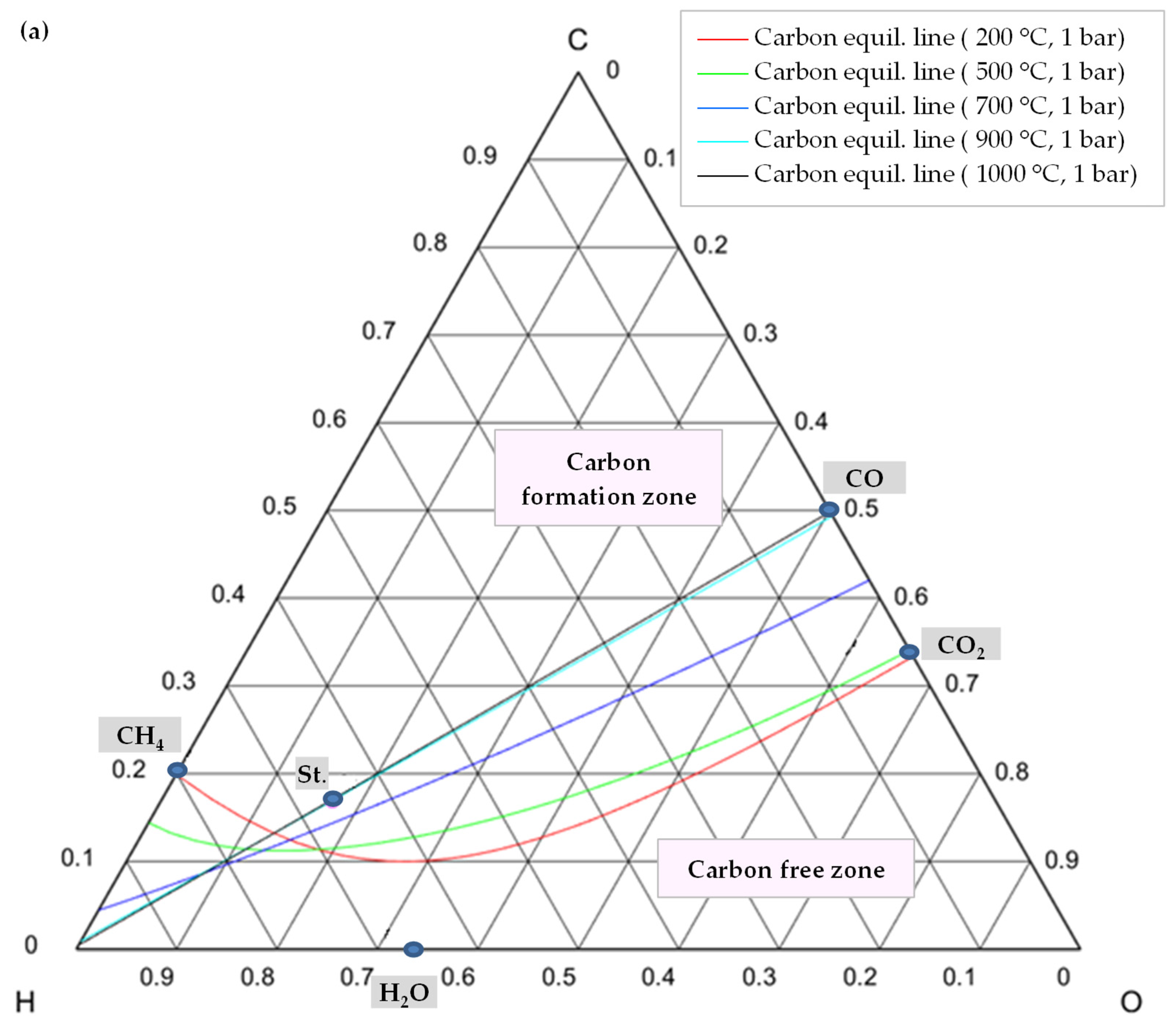
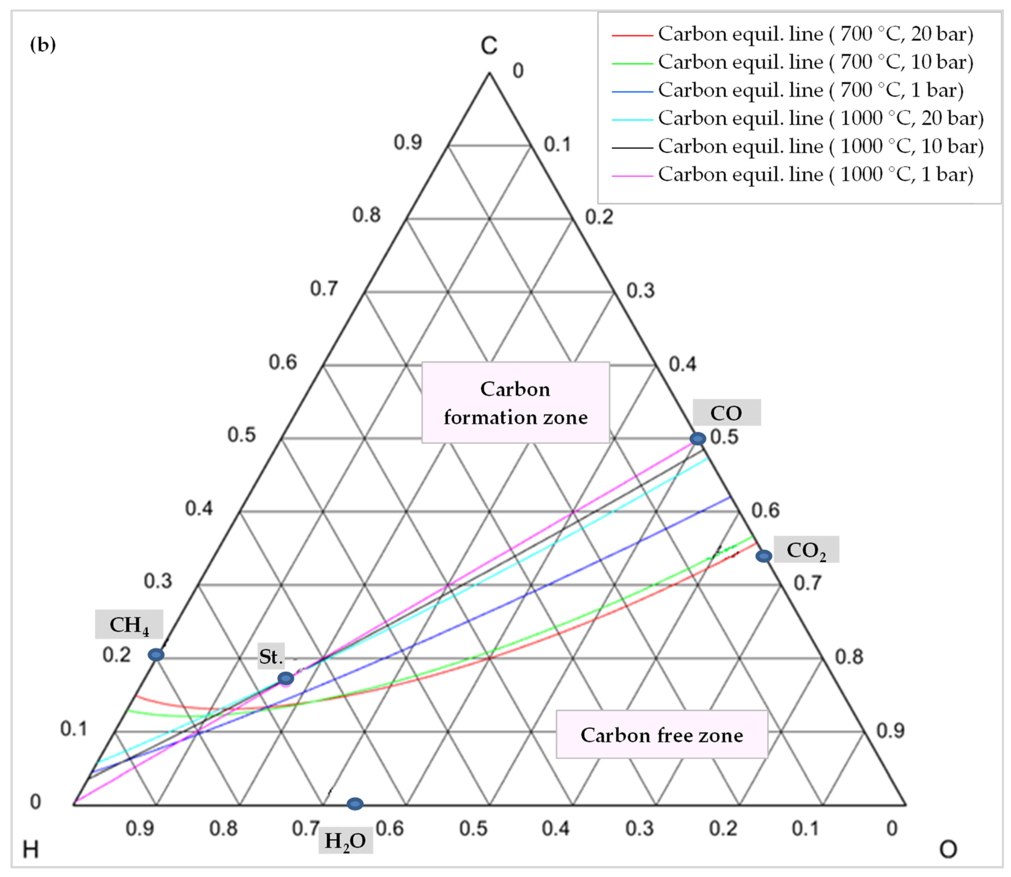
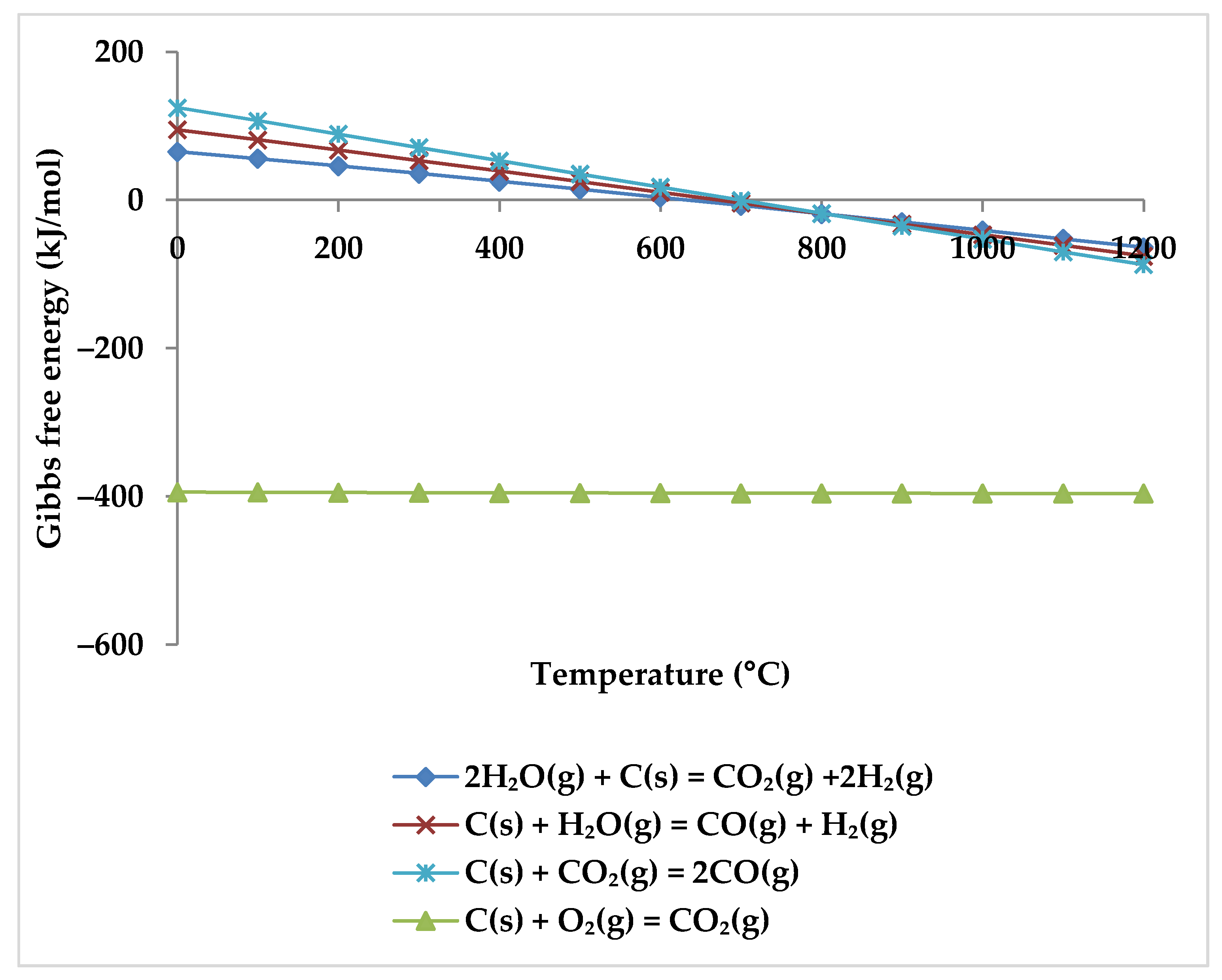
7. Coke Formation Assessment

One of the significant problems faced by industrial reforming processes is the production of solid carbon (coke), which leads to catalyst deactivation [64]. In the reforming processes, coke forms through four reactions (Equations (6), and (8)–(10)). They have a comparatively low equilibrium constant, making them very sensitive to variations in reactant molar ratios. At low temperatures (<700 °C), the Boudouard and Beggs reactions (Equation (8) and Equation (9), respectively) and the hydrogenation of CO2 (Equation (10)) dominate, but at high temperatures, CH4 largely decomposes to form carbon deposits (Equation (6)) [51,67,76] (Figure 13).
2 CO     CO 2 + C ( s )                   Δ H 298 0 = 172   kJ mol                     Boudouard   reaction ,
CO + H 2     C ( s ) + H 2 O             Δ H 298 0 = 131   kJ mol             Beggs   reaction ,
CO 2 + 2 H 2     C ( s ) + 2 H 2 O             Δ H 298 0 = 90   kJ mol               CO 2   hydrogenation   reaction ,
Therefore, according to these reactions, the amount of synthesis gas that can be produced is negatively impacted by carbon formation. As a result, preventing the formation of carbon is highly preferred due to these detrimental impacts [77].
In order to comprehend how the development of coke is lessened, it is advisable to examine the C-H-O atomic phase diagram (Figure 14). A ternary C-H-O phase diagram depicts possible phases and their equilibria for a mixture of three components of C, H, and O under constant temperature and pressure conditions. With the help of this technique, an equilibrium line (boundary line) is drawn for any desired pair of temperature and pressure, which separates the graph into its upper and lower regions. The region above this line is the area where carbon formation is thermodynamically favored, and the region below it is the area where carbon formation is not favored. Moreover, each point on the graph indicates a mixture with the specific composition of atomic species of C, H, and O (e.g., CO is a mixture of 50% C and 50% O).
Thus, knowing the reaction temperature and pressure, as well as the ratio of C, H, and O atoms, allows one to determine whether or not carbon is formed for that specific mixture. Figure 14a shows the carbon deposition equilibrium lines for several temperatures at 1 bar, and Figure 14b shows the lines for two temperatures at three different pressure levels. Small circles on these images represent the main species, namely CO, CO2, H2O, CH4, and the stoichiometry ratio of feed gases (St., CH4:CO2:H2O:O2 = 1:0.5:0.25:0.125).
As illustrated in Figure 14a, by raising the temperature while maintaining the same pressure, the carbon formation equilibrium lines shifted upward, expanding the coke-free zone. The reason is that as the reaction temperature rises, the chemical equilibrium of reactions of Equations (8)–(10) shifts toward consuming carbon to produce carbon monoxide or carbon dioxide (reverse direction of these reactions) [49].
In contrast, the equilibrium line shifts downward, and the coke-free zone shrinks when pressure rises at a constant temperature. For higher temperatures, this change is less pronounced. As shown in Figure 14b, the coke-free zone does not change significantly at 1000 °C since the equilibrium lines are adjacent to one another. Furthermore, as evident from these diagrams, carbon formation is always conceivable in a TRM process when the feed gas ratio is stoichiometric (point St.) and is not affected by temperature. The stoichiometric point must, therefore, move lower or to the right of the relevant equilibrium line in order to prevent carbon production. This suggests that the content of O2, H2O, and/or CO2 should be increased. However, this results in a reduction of the heating value of the produced syngas [77,78]. Moreover, oxygen and steam can not only reduce the formation of coke, but also remove it through Equation (11) and the reverse reactions of Equations (9) and (10), which also explain why CO2 conversion decreases by adding O2 in the reactor feed [52].
C + O 2     CO 2               Δ H 298 0 = 393.7   kJ mol ,
Compared to increasing steam concentration, increasing oxygen concentration may be more successful in minimizing coke formation for industrial reforming processes because the conversion rate of the reaction between carbon and oxygen is faster and more efficient even at low temperatures (Figure 15), which makes it economically desirable [79]. However, due to the exothermic nature of the reaction with oxygen, overheating is a distinct possibility [80], making precise temperature control important. However, this can be achieved by controlling the partial pressure of oxygen.
What is more, in comparison to individual SRM, DRM, and POX processes, or a combination of SRM and DRM (bi-reforming of methane, BRM), the inclusion of three oxidants (CO2, H2O, and O2) in the TRM process decreases carbon deposition considerably [51] as shown in Figure 16.
Another point is that the influence of reaction kinetics and the type of the catalyst on carbon formation should be paid attention to. In other words, in the carbon-free zone, carbon can develop due to kinetically restricted reactions or can be prevented by a proper catalyst type even when operating in the carbon formation zone [77].

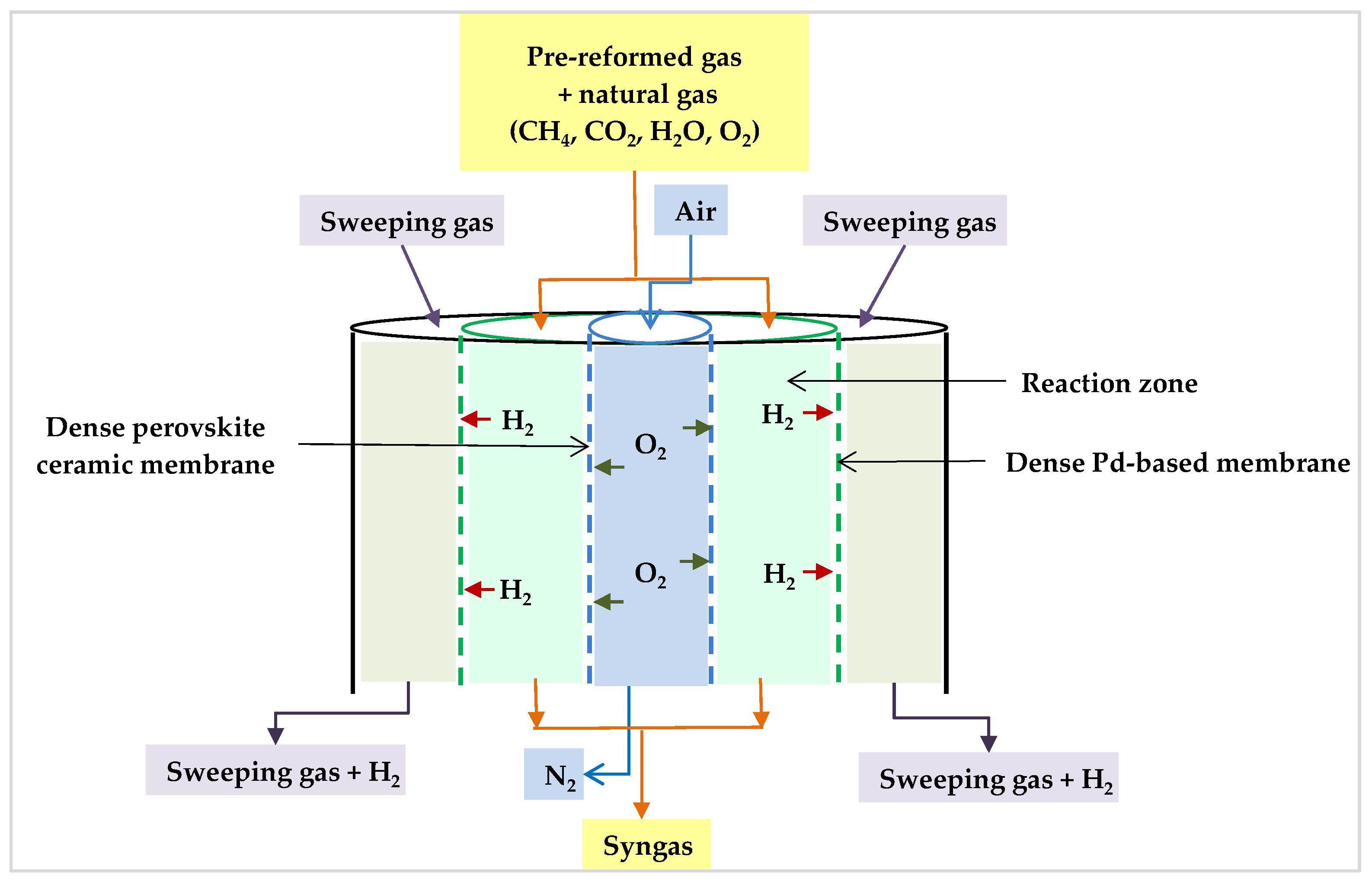
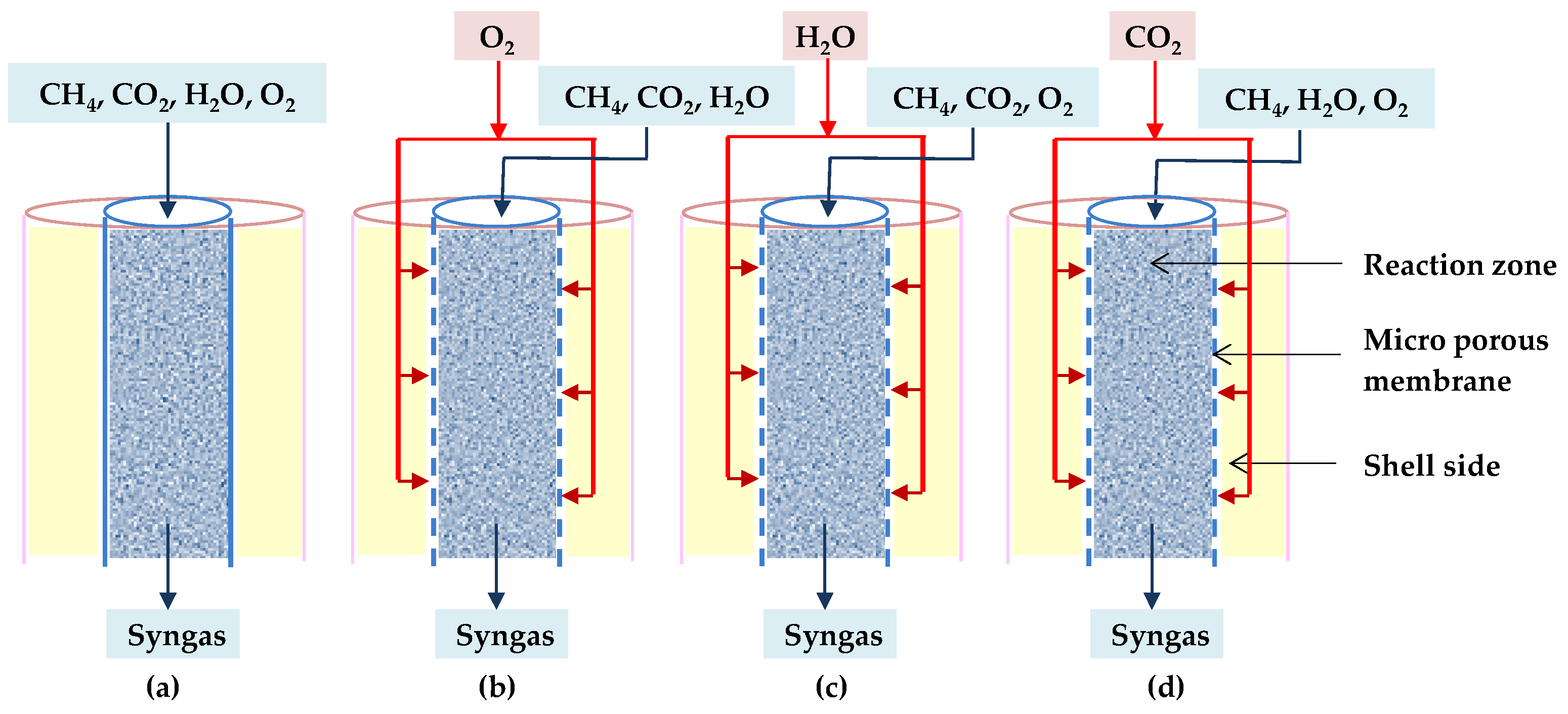
8. Reactor Technology Evaluation

The most common reactor configuration used to investigate TRM in the literature is a fixed-bed reactor operating under adiabatic conditions. These reactors have smaller sizes and cheaper capital and operational expenses. Moreover, they surpass the non-adiabatic TRM processes at high pressure because, in adiabatic conditions when the pressure rises, the temperature also increases and can compensate for the effect of high pressure. However, these reactors demand high oxygen to maintain the temperatures, which increases the occurrence of hot spots [81].
Khajeh et al., on the other hand, demonstrated that employing a fluidized-bed tri-reformer instead of a fixed-bed reactor offers some advantages through a mathematical comparison. A fluidized bed aids in better mixing, improving heat transfer, and reducing the temperature differential in the catalyst bed, which results in a smooth and uniform distribution of heat. Endothermic reactions benefit from this proper heat distribution. Thus, the conversion of methane and CO2 and the yield of H2 in a fluidized bed reactor are greater. Furthermore, in a fluidized bed, the combustion of methane is faster than in a fixed bed, which leads to more methane consumption, while the amount of oxygen required to achieve maximum H2 yield is lower and saves more energy. Furthermore, improved heat regulation throughout the reactor lowers the hot spot temperature by around 250 °C. In addition, fluidization reduces pressure drop and diffusion constraints. From this point of view, reactors with fluidized beds appear to be more promising [82]. However, catalyst attrition is a problem for these types of reactors. Therefore, the system requires a catalyst with sufficient mechanical stability to prevent particle elution and attrition [83,84,85].
Furthermore, there is another reactor layout that aids in lowering hot spot temperatures. In this way, the temperature profile of the reactor may be controlled by delivering oxygen into the reactor from multiple locations. Rezaei et al., for example, found that dosing oxygen at four evenly spaced points along the length of the reactor keeps the reactor’s maximum temperature below 1300 °C, whereas when only one injection point is available, the reactor temperature rises to 1879 °C near the inlet point. This rapid increase in reactor temperature around the injection points is due to the exothermic reaction of methane combustion. Then, the temperature steadily drops as the endothermic reforming reactions consume this heat content. However, when numerous injection points are employed, the temperature of the highest peak is suppressed because the distribution of oxygen across the catalytic section leads to the stepwise release of heat from the oxidation of methane. As a result, having more injection points results in fewer temperature peaks at the reactor entrance [75]. Farsi et al. also reported similar data and reached the same conclusion [86].
It is also feasible to boost synthetic gas production by distributing all feed components across more than one injection point. In this regard, a mathematical model developed by Fekri Larry et al. revealed that dividing a typically fixed bed reactor into three equal sections and distributing preheated steam and carbon dioxide among these sections results in more hydrogen production, less oxygen consumption, and an acceptable H2/CO ratio in the final product. In this modified reactor, methane is given directly to the reactor, whereas oxygen is added to the first section, and carbon dioxide and steam are distributed between the sections. Injecting steam and carbon dioxide into the second and third beds enables the reversible reactions, which are at equilibrium conditions, to progress toward higher hydrogen production. When compared to traditional designs, this concept has the potential to increase hydrogen generation by 2.93% [40].
The idea of multiple injection points can lead one to think about membrane reactors as an alternative to conventional reformers. In this regard, Rahimpour et al. studied a permeable membrane reactor. They suggested that a multi-tubular fixed bed reactor would benefit from selective permeable oxygen and hydrogen membranes. This reactor was made up of two concentric pipes, similar to a tube-shell system (Figure 17). The inner tube walls were dense oxygen permeable membranes (perovskite ceramic membrane), and the outer porous stainless-steel tube supported a dense Pd-based membrane coating. Co-currently, the air is delivered into the oxygen membrane to permeate into the reaction side, and then the generated hydrogen penetrates through the Pd-based membrane on the opposite side of the reaction zone to be swept by a sweeping gas. The benefits of this reactor include the generation of pure hydrogen and the equivalence of the H2/CO ratio for methanol production at lower inlet temperatures. In addition, the oxygen membrane omitted the air separation requirements, reducing the need for an external pure oxygen source and resulting in considerable cost savings. Moreover, the oxygen membrane distributes oxygen and, therefore, the heat along the reformer, resulting in an optimal temperature profile within the reactor [87].
Although perm-selective membranes increase control of the TRM process’s kinetics and temperature profile, substantial permeation fluxes and harsh working conditions favor the use of porous membranes over perm-selective membranes [64]. Jardim et al. investigated a porous membrane reactor to determine the optimal oxygen distribution for adiabatic operation. They created a model of a packed bed tube with a porous membrane wall that was inert. From the shell (exterior compartment), oxygen was delivered into the feed stream as well as the α-alumina membrane. They discovered that while the oxygen partition does not affect the overall performance of the reactor, it has a considerable impact on the thermal behavior. In addition, the percentage of oxygen delivered at the feed to that permeating via porous membrane should be 80% to avoid hotspots. The temperature profile showed no hot spot but rather a cold spot (725 °C) in the inlet region due to the rapid reforming processes, followed by a smooth rise in the equilibrium temperature (953 °C). As a result, the porous membrane reactor can execute TRM adiabatically and safely with a large amount of oxygen, but it imposes a non-uniform oxygen distribution that rises with reactor length. Furthermore, due to the low pressure of methane in the outlet zone, over-oxidation may occur. To prevent an undesirable flow of oxygen, the pressure drop, the transmembrane pressure, and the permeability of the membrane should all be adequately constructed and managed [64].
Further, Khademi et al. demonstrated that the feed gas distribution to the reactor influences the reactor sizing. They looked at three different types of micro-porous membrane reactors as well as conventional ones. These reactors are distinguished by their feed injection techniques. In each proposed membrane reactor, only one of the reactants (O2, H2O, or CO2) is distributed along the reaction zone across the membrane. When O2, H2O, or CO2 are distributed, the reactors are called O-TRM, C-TRM, or H-TRM, respectively, as shown in Figure 18b–d [88].
These authors also developed a mathematical model of the required minimum length of each reactor to produce syngas with desired H2/CO ratio, which varies in the range of 1.7–2.3 in terms of acceptable CH4 and CO2 conversion. Their results indicate that the minimum required lengths are in this order: TRM < C-TRM < O-TRM < H-TRM. As a result, the conventional reactor has the shortest length, implying that the reforming reactions reach the equilibrium more quickly, whereas the membrane reactors require more length to achieve the desired behavior. Table 5 shows why they should be longer [88].
The literature also shows that for all designs, increasing the inlet gas temperature reduces the reactor length by speeding up the rate of conversions [46,88]. However, there is an optimum point for the O2/CH4 ratio. On the one hand, as the O2/CH4 ratio increases, the length of the reactor decreases since more heat is generated, which activates reforming reactions, and also more methane is consumed. Increasing the O2/CH4 ratio, on the other hand, results in more CO2 production via methane combustion, requiring a longer reactor to convert the produced CO2. The size of the reactor remains nearly constant at low H2O/CH4 ratios; however, at high H2O/CH4 ratios, more length of the reactor is required to achieve satisfactory CO2 conversion due to a drop in the RWGSR rate [88].
Despite the benefits of membrane reactors, they cannot prevent coke formation because the oxygen distribution via membrane technology reduces the concentration of oxygen, whereas an O2/CH4 ratio of more than 45% is required to avoid coke formation and achieve high yields [81].
Another type of reactor is the autothermal plug flow reactor, which has received less attention in the literature. An autothermal reactor consists of two chambers: a combustion chamber (homogeneous section) and a catalytic chamber (heterogeneous section). The combustion chamber is a special refractory chamber that can resist the high temperatures generated by methane oxidation and prepare the heat required for the reforming processes. In the catalytic chamber, reforming reactions are performed in the presence of a catalyst. This concept was explored for the DME plant’s synthetic gases, in which lower syngas ratios are adequate [10]. When designing a plug flow reactor, the length of the homogeneous and heterogeneous sections, as well as operational variables, are critical. A major criterion for constant inlet temperature and composition is that the homogenous section is long enough to have the required residence time for combustion, leading to an increase in the temperature needed for the reforming reactions. If the oxygen conversion is greater than 99.9%, the homogeneous segment is regarded as long enough. The needed residence time is, however, greatly influenced by the inlet temperature and feed composition. By increasing the inlet temperature, the ignition is accelerated and the needed dwell time is reduced. The effect of the temperature is exponential and is more intense when there is no hydrogen in the input. Furthermore, the necessary residence time is strongly influenced by the flow rate of oxygen. With more oxygen, the ignition occurs more quickly, requiring a shorter residence period. Moreover, the flow of steam or carbon dioxide at the reactor inlet increases the required residence time linearly as they simply dilute the reactants and do not contribute to the combustion reaction. Additionally, the findings of verified mathematical models reveal that the dependency of hydrogen generation on the homogeneity to overall length ratio is stronger than the dependency of carbon monoxide generation. The ideal ratio for hydrogen generation is approximately 0.37, whereas the optimal ratio for carbon monoxide production is around 0.4, and the ratio of H2/CO falls monotonically as the length ratio increases. These findings make it possible to adjust the reactor length according to the desired products ratio [10]. This design reduces catalyst degradation, but due to negative CO2 conversion it performs poorly when generating synthetic gases with an H2/CO = 2.0 ratio required [81].
The next less attractive TRM reactor design in the literature is the heated reactor. In a heated reactor, which resembles the industrial SRM design, the required heat is supplied externally in the arrangement of bundles of tubes within a furnace. The performance of this reactor is superior to the autothermal reactors at a high desired syngas ratio for methanol production and adiabatic reactors at low-pressure ranges (below 40 bar). However, considering the total CO2 emission including furnace, its CO2 conversion is lower [81].
In other work, Ahmed et al. compared the performance of methane reforming in a spherical reactor with a cylindrical one using a multi-objective optimization (MOO) model. The notable result was that the spherical reactor offers substantially lower reactor pressure loss and consequently about 70% less power dissipation for the same amounts of H2 production and CO2 emission. As a result, spherical reactors outperform tubular reactors in terms of energy savings [89].

9. Energetic and Exergetic Considerations

In this section, the benefits of integrating the TRM process with upstream and downstream units are first examined, and then the effects of various parameters on the exergy of the system are discussed. The main results are presented in Table 6 and Table 7.
In the TRM process, unlike other CO2 mitigation techniques, owing to the possibility of simultaneously feeding CO2 with other inlet gases, a CO2 separation step before its recovery and utilization can be omitted. As a result, this reduces the necessary energy consumption by CO2 capturing. For example, CO2 capturing using chemical absorption with alkanolamines consumes 20% of the energy in a coal-fired power plant [90,91]. Additionally, a calculation-based comparative study revealed that TRM is preferred over other reforming methods (i.e., DRM and SRM) in terms of energy efficiency [4,63]. According to the standard enthalpies, the TRM reactions use around 29% less energy compared to the BRM reactions [67] as the heat generated during exothermic reactions (i.e., partial combustion of CH4 and the WGSR) can supply the needed energy for reforming reactions [4,67,92].
The work of Halmannand and Stenfield showed that the TRM of the flue gases released from coal- and gas-fired burners of power stations containing N2 leads to fuel saving in comparison to conventional methanol or H2 production processes with SRM. Fuel-saving for the methanol and H2 production via TRM would be of the order of 31% and 75%, respectively, for both flue gases. Moreover, TRM results in high exergy efficiency for methanol and H2 production for these two flue gases of around 72% and 74%, respectively [93].
In another study, Minutillo and Perna investigated how a TRM process may be combined with a power plant and a methanol synthesis process to generate both electricity and methanol. They proposed using a heat recovery system to recover the thermal energy from the produced syngas and to use it to generate high-pressure steam that could be sent to the power island to boost electrical output. According to the results of a numerical approach, the thermal efficiency and the system efficiency can exceed 83% and 55%, respectively [94].
Compared to a traditional coal gasification plant for methanol production (CTM), the combination with a coke oven gas plant (COG) coupled with TRM can increase the carbon utilization and energy efficiency of the process by 4.3% and 11.4%, respectively. In addition, if the WGS unit is omitted in the integrated process, these efficiencies become 14.5% and 16.8% higher than those of the conventional CTM process, respectively [95].
Likewise, when a TRM process is coupled with coal to ethylene glycol technology (CTEG) in combination with a coke oven gas separation unit (COGS), its exergetic efficiency is the highest among conventional CTEG processes and the integration of the CTEG with other reforming processes such as SRM, DRM, and BRM. The order of exergy efficiencies is 10.3, 30.5, 34.9, 38.8, and 40.8% for CTEG, CTEG-SRM, CTEG-DRM, CTEG-BRM, and CTEG-TRM, respectively. The reason is that the reforming processes have higher efficiency, although they consume more utilities than the conventional CTEG method [63].
However, when employing pure oxygen, the energy necessary for an oxygen plant must also be taken into account. A cryogenic facility, for example, consumes 0.37 kWh/kgO2 energy [92]. When air is utilized instead of pure oxygen, the nitrogen in the air stream reduces thermal efficiency since it does not react, raising the required compression and heating energy [96].
If the TRM process is combined with oxy-fuel combustion, the negative effects of nitrogen can be counteracted. In this configuration, a water electrolysis unit supplies the required oxygen for the oxy-fuel combustion unit and adds the generated hydrogen to the methanol production unit [39]. The net energy efficiency of this plant is 62%, which is significantly higher than the direct CO2 hydrogenation method for methanol production [41]. Compared to air–fuel combustion, this configuration can boost the process’s CO2 valorization potential by more than 3 times at the expense of its profit-generating potential because of the additional cost of water electrolysis [39,72]. Nonetheless, it is possible to enhance the profit of this concept by increasing the water electrolysis throughput and directing the extra produced oxygen to the TRM process to reduce TRM heat duty. This modified water electrolysis unit consumes less energy than a cryogenic unit [45].
A higher energy efficiency is achieved when the TRM process is integrated with downstream units [9], especially when using an optimal heat exchanger network [53,97], because the recovered heat from the reforming plant can provide the electric power required for the syngas compression [94].
Zhang et al. developed an optimal heat exchanger network for an integrated process of TRM and methanol production to minimize utility and capital costs. They used the general algebraic modeling system (GAMS) for their calculations and corroborated the results using ASPEN Energy Analyzer. According to their design, the gross energy saving is 34.3% when just utility cost reduction is included, but 32.2% when both utility and capital cost minimization are considered. This slight decrease in energy efficiency is because adequate heat exchange across the process flows reduces water and electricity costs while increasing capital costs since more heat exchangers are required. Moreover, when BRM is considered instead of TRM in this integration, BRM uses less specific energy (11.5 kWh/kgCO2 vs. 19.0 kWh/kgCO2) but produces twice less methanol than TRM [53].
These authors also conducted the same research to merge the TRM process with the dimethyl ether (DME) synthesis process, which yielded comparable results. The optimal heat exchanger network results in gross savings of 37% for the whole process and 33.3% for the DME process compared to the original case. Furthermore, the TRM process consumes a little more energy compared to the BRM for DME synthesis (0.7 kWh/kgCO2 more energy) while generating slightly more DME (0.06 kg/kgCO2). Therefore, the energy saving of the TRM method is 0.97 KW/kgCO2 higher than BRM [97]. However, a more detailed economic examination considering catalysts and kinetics evaluation is required to completely show the economic viability of DME synthesis by the TRM process.
Table 6. Comparison of integrated TRM processes with conventional ones.
ProcessCompared toSaving Type: Amount %Efficiency Type: Increased Amount %Ref.
CO2 separation unitChemical absorption with alkanolaminesEnergy of a coal-fired power plant: 20% [90,91]
TRM reactionBRM reactionsEnergy: 29% [67]
TRM of the flue gases released from coal- and gas-fired burners of power stations containing N2Conventional methanol production with SRMFuel: 31%Exergy: 72%[93]
TRM of the flue gases released from coal- and gas-fired burners of power stations containing N2Conventional H2 production with SRMFuel: 75%Exergy: 74%[93]
Combined TRM with COG and WGS unitConventional CTM Carbon utilization: 4.3%[95]
Energy: 11.4%
Combined TRM with COGConventional CTM Carbon utilization: 14.5%[95]
Energy: 16.8%
Combined TRM with CTEG and COGSCTEG Exergy: 30.5%[63]
Combined CTEG and SRMExergy: 10.3%
Combined CTEG and DRMExergy: 5.9%
Combined CTEG and BRMExergy: 2.0%
Combined TRM with oxy-fuel combustion equipped with water electrolysis unitDirect CO2 hydrogenation method for methanol production Net energy: 10%[41]
Combined TRM with methanol production WITH heat integrationCombined TRM with methanol production WITHOUT heat integrationGross energy:
34.3% (minimizing utility cost)
[53]
32.2% (minimizing utility cost and capital cost)
Combined TRM with methanol production with heat integrationCombined BRM with methanol production with heat integrationSpecific energy: 4.0 kWh/kgCO2 [53]
Combined TRM with DME production WITH optimal heat exchanger networkCombined TRM with DME production WITHOUT optimal heat exchanger networkGross energy:
37% (whole process)
[97]
33.3% (DME process)
Combined TRM with DME production with optimal heat exchanger networkCombined BRM with DME production with optimal heat exchanger networkEnergy: 0.97 kWh/kgCO2 [97]
Table 7. Effect of different design factors on the energy and exergy efficiency of the system [98].
Design FactorEffect on Energy EfficiencyEffect on Exergy Efficiency
Reactor inlet temperatureD 1N 4
H2O concentrationDI
Reactor pressureI 2N
CO2 concentrationII
Air concentrationO 3O
Reactor lengthOI
1 D: Directly proportional. 2 I: Inversely proportional. 3 O: There is an optimum. 4 N: No substantial change.
Sadeghi et al. conducted a thorough investigation of the effects of several design factors on system performance. Given that the main products are hydrogen and carbon monoxide, the overall energy efficiency of the system and the reactor are as follows:
η reactor = n H 2 , outlet ×   HHV H 2 + n CO , outlet   ×   HHV CO n CH 4 , inlet   ×   HHV CH 4   ×   100 ,
η overall = n H 2 , outlet   ×   HHV H 2   + n CO , outlet   ×   HHV CO n CH 4 , inlet   ×   HHV CH 4 + W CH 4 , COMP + W CO 2 , COMP + W AIR , COMP   + W PUMP   ×   100 ,
Since H2 is the most valuable product and has the highest HHV (higher heating value), increasing any parameter that results in a higher H2 concentration in the product will increase energy efficiencies under Equations (12) and (13). Therefore, increasing the reactor inlet temperature or H2O concentrations or decreasing the reactor pressure or CO2 concentration increases the system efficiency. Additionally, if air is utilized instead of O2, there is an optimum air concentration because the N2 molar flow rate also increases, increasing the compressor workload. There is even an optimal reactor length since there is no chemical potential in the mixture beyond a specific length of the reactor to produce high-quality syngas [98]. Table 7 summarizes these findings.
The same authors similarly assessed the exergy of the system due to the irreversibility that occurs during the process, which is not considered by energy analysis alone. They argued that increasing the volume of H2O and CO2 as well as the length of the reactor reduces the exergy efficiency of the system. However, when the inlet temperature exceeds 900 °C and the reactor pressure increases, there is no substantial change in the system’s exergy efficiency [96,98]. Rather, there is a value for air (say, 3.35 mol/s) at which the overall energy efficiency of the system is at its lowest. The reason is similar to that previously stated for energy efficiency due to the presence of N2 [98]. Table 7 highlights the effect of various parameters on the system’s exergy efficiency.

10. Economic Assessment

This section describes how specific factors and the TRM process, when combined with other facilities, affect system costs. Additionally, the economic advantages of using the TRM method in comparison to alternative processes are covered.
Research shows that when the synthesis gas produced by TRM and BRM processes is delivered to a methanol plant, the price of methanol can be competitive with the traditional method of methanol production. TRM’s specific capital cost (CAPEX/tonMeOH) and specific operating cost (OPEX/tonMeOH) are also somewhat lower than BRM’s (3.7% and 1.3%, respectively) [99]. Compared to BRM, TRM has a lower specific CAPEX at any capacity level because it uses oxygen, which allows the process to become more efficient and thus reduces equipment size, and this behavior becomes more visible at large production levels. However, for all scenarios, the specific CAPEX decreases as methanol production increases [8,92]. More than 40% of the total CAPEX for these technologies comes from the cost of purchasing equipment [8]. The dominant equipment cost of the BRM and TRM belongs to the reformer (a box furnace) and the air separation unit (ASU), respectively [92]. Nonetheless, BRM has a relatively lower OPEX because an air separation unit is not required [25].
A comparison of the TRM and BRM techniques with a hydrogenation-based process, in which CO2 reacts with H2 to produce methanol, reveals that the investment costs of a hydrogenation-based process are approximately 2.5-times lower than those of the TRM and BRM processes for any capacity because a hydrogenation-based process does not require additional processing units such as pre-reformers or reformers. However, only a small fraction of the total cost is capital costs (about 2% and 10% for hydrogenation and reforming processes, respectively) and the rest of the costs are the operating costs. Since the cost of hydrogen from renewable sources such as wind, sun, biomass, hydropower, and specifically the solar systems with high-temperature electrolysis is high, the reforming process is advantageous over the hydrogenation approach and it has superior results by lowering the yearly total cost of methanol (37% with BRM and 39% with TRM). Furthermore, when the methanol plant size increases, the operating costs decrease, and the gap between the hydrogenation process and BRM and TRM becomes slightly bigger. Therefore, maybe in the future, the availability of free hydrogen from industrial by-products or cheaper hydrogen from renewable sources would actively lower the cost of methanol synthesis by hydrogenation. Until then, however, BRM and TRM can be seen as a transition technology from a traditional to an alternative methanol plant as they not only have a higher investment appeal than a traditional methanol factory, but they also have environmental advantages [8].
Another study also shows that when water electrolysis utilizing carbon-free energy to be converted into O2 and H2 is coupled with TRM, it outperforms the direct CO2 hydrogenation process for producing methanol in terms of economic feasibility [41]. A significant portion of CAPEX and OPEX (34% and 51%, respectively) is accounted for in the water electrolysis process. Furthermore, a discounted cash flow (DCF) model along with a sensitivity study revealed that a break-even point could be achieved with a methanol price of USD 491/ton, a net payout time (NPT) of 19.8 years, and a net present value (NPV) of USD 11.4 million after 20 years of operation. As a result, for their facility to be commercially feasible, a high methanol sale price of around USD 500/ton is necessary [41].
Likewise, if a TRM process is combined with methanol production, it will be a cost-effective method of turning waste carbons into usable fuels and chemicals [53]. For instance, Borreguero et al. demonstrated that the investment in methanol production utilizing TRM with natural gas, including a pre-reactor to convert ethane and propane to syngas, could be recovered in 7 years, and the process would be economical even with a 22% drop in methanol production mass flow. However, methanol prices lower than EUR 0.28/kg lead to negative NPV values [46]. Heat integration, when electricity is utilized for chilling below 40 °C, lowers the utility expenses by 78.4% and capital costs by 43.8%. [53].
Similarly, the combination of a TRM process with CTEG technology and a COGS unit reduces the capital investment by 18.82% compared to a typical CTEG process. The reason is that this linked process does not require WGS units and consequently has lower equipment costs. In addition, since the TRM process uses less coal and steam than other reforming processes, this combination results in the lowest production costs. Furthermore, the TRM method has the highest internal rate of return (18.85%). Therefore, the CTEG process in combination with a TRM system offers the best economic results compared with the conventional CTEG process or a combination of CTEG with SRM, DRM, and BRM processes [63].
In addition to the combination of these units, process parameters and design factors can also alter process costs. For example, Sadeghi et al. reports on the effect of feed composition and process parameters on the cost of the TRM process. They found that an increase in the concentrations of CO2 or H2O, reactor pressure, or inlet temperature, results in higher total capital investment, but for different reasons: this is mostly due to the necessity for larger heat exchangers in the case of higher H2O concentrations and inlet temperatures, the higher cost of CO2 compressor for more CO2 flow rates, and a more expensive compressor and a reactor in the case of high pressure. However, there is an ideal value for the air concentration and the length of the reactor since two opposing effects are occurring at the same time. On the one hand, the capital cost of an air compressor grows as air concentration rises. Increased air concentration, on the other hand, results in a greater reactor exit temperature, a smaller heat exchanger size, and thus a lower capital cost. A longer reactor increases the capital cost, but also increases the concentration of H2 in the produced syngas, outstripping the total investment cost. However, there is an optimum length (e.g., 1.9 m) where the unit cost of synthesized gas produced is minimal. When the length of the reactor is greater than this value, increasing the length of the reactor has little effect on the amount of hydrogen production. Thus, the yield of hydrogen remains relatively constant, while the total cost of the system increases. However, increasing the air molar flow rate, reactor pressure, and either CO2 or H2O concentrations causes a continuous rise in the total product unit cost, whereas increasing the reactor inlet temperature reduces the total product unit cost of the system at a specific value (e.g., 1200 K), in which the H2 concentration increase overcomes the increase in the total product unit cost of the system. As a result, the unit cost of produced syngas is computed as USD 4.48/GJ when the TRM process is optimized [98].
Furthermore, other arguments exist to support the requirement for TRM to operate at higher pressures. According to Dwivedi et al., TRM reactors operating with large volumes of feed gas at high temperatures and atmospheric pressures (850 °C, 1 atm) are not feasible in terms of capital costs due to the reactor’s large size [20,100]. Ren et al. asserted, for example, that running the TRM at higher pressures is more cost-effective due to downstream units where the manufacture of chemicals and fuels from syngas is kinetically favored at higher pressures, such as methanol production at 50 bar. Additionally, methane as a feedstock is often stored and supplied at higher pressures. Furthermore, using the tri-reformer at a greater pressure would be industrially more efficient [47]. There is also evidence that process conditions with high pressures are the norm for SRM, DRM, and catalytic POX, which operate at pressure ranges of 20–30 bar, 10 bar, and 15–40 bar, respectively [101]. As a result, the recommendation is to employ a TRM reactor that operates at high pressures of 30 bar to limit the size of the reactor and therefore lower the process’s capital expenses [75].
Another case in point is the use of fluidized bed membrane reactors to reduce operational expenses. They can cut capital costs by increasing hydrogen production rates, decreasing heating energy needs, and removing or downsizing downstream gas treatment and purification facilities [102,103].
In conclusion, due to the concurrent effects of uncertainties in key economic factors such as natural gas prices and CO2 taxes on the plant’s NPV, simulation with the Monte-Carlo method revealed that when TRM is used for methanol production, there is an 84% probability of a methanol plant being feasible. If the natural gas and CO2 tax costs increased to USD 0.1569/stdm3 and USD 140/1000 kgCO2, respectively, this plant would not remain operational since it would lead to a negative NPV. NPV is most sensitive to the price of natural gas, followed by changes in the price of O2 and then CO2. However, an 80% increase in the price of O2 or CO2 still results in a positive NPV. The proposed plant included a pressure swing adsorption (PSA) unit that recovered hydrogen from unreacted gases to improve the syngas H2 ratio and generated 2000 tons/day of methanol. This facility has a NPV of USD 161 million during a 15-year economic life based on a methanol selling price of USD 390/ton [75]. Moreover, the profitability of the TRM process is highly dependent on the price of the final commercialized products (e.g., methanol) [46]. Borreguero et al. highlighted that the TRM process is economical at a methanol price of 0.320 USD/kg. Negative NPV parameters are determined at lower prices. This is consistent with the break-even point, implying that the process is economically viable [46]. Shi et al. also found that when water electrolysis is coupled with TRM, the break-even point is USD 0.491/kg of methanol [41].

11. Environmental Assessment

With a share of 47% of global CO2 emissions, fossil fuel power plants are the major contributors to anthropogenic CO2 emissions [104]. According to calculations, flue-gas treatment with TRM can reduce CO2 emissions by 59% and conserve fossil fuels by 75% [26,94,105]. Therefore, reforming-based pathways, except for SRM, can be seen as a promising option for CO2 treatment during the transition from a carbon-based to a carbon-free production [8,99]. Specifically, the TRM process leads to the greatest avoidance of CO2 emissions when methanol production is considered instead of other products [45]. For instance, for producing methanol, the CO2 emissions when using TRM and BRM technology are 1.1- to 1.4-times lower than conventional technologies (SMR-based methanol plants), which release 1.49–1.9 tonCO2/tonMeOH into the air. Between the two TRM and BRM processes, the TRM process emits lower CO2 (1.39 vs. 1.41 tonCO2/tonMeOH) [8,75,106,107,108,109].
When a TRM-based methanol plant uses a PSA hydrogen separation unit and a cryogenic air distillation unit, its net CO2 emissions are 0.91 tonCO2/tonMeOH, which is half of the CO2 emissions of a conventional plant and 35% lower than a TRM-based methanol plant, which maintains oxygen from water electrolysis [75] with net emissions of 1.39 tonCO2/tonMeOH [8]. Methanol, on the other hand, may be generated with net negative carbon emissions of −0.14 tonCO2/tonMeOH when utilizing a TRM-based methanol plant paired with carbon-free water electrolysis, which results in a net CO2 reduction of 570,000 tons per year, when the plant’s production rate equals 2095 tons of methanol per day [41].
However, the product of reforming technology is syngas, which can be used as a raw material to make low-emission synthetic fuels such as hydrogen, methanol, synthetic gasoline and DME, or it can be used directly to generate electrical energy and heat in high-temperature fuel cells [110]. Therefore, reforming technology is a more sustainable alternative for producing clean fuels. For example, compared to the conventional CTM process, combining COG and coal gasification with a TRM process for methanol production can reduce CO2 emissions by 44% [95], and the combination for ethylene glycol synthesis decreases overall CO2 emissions by 59% [63]. Integrating fossil-fuel-fired power stations with the TRM process can alleviate CO2 emissions up to 83–90% [9,71]. However, because this unique method still uses steam and energy, the CO2 emission reduction is mostly attributable to the direct avoidance of CO2 emissions rather than indirect CO2 emissions [63].
Furthermore, controlling operating conditions favors the desired environmental benefit. For example, increasing the inlet gas temperature above a certain value promotes the consumption of CO2 [111]. Alternatively, raising the O2/CH4 ratio from 0.1 to 0.2 reduces net CO2 emissions by roughly 22% [36] due to the lower energy requirement for heat delivery as a result of introducing oxygen to the reforming plant [8].

12. Safety Assessment

When hydrocarbons are combined with oxygen at temperatures above the auto-ignition point, an explosion can occur. As a result, suitable precautions must be taken in large-scale industrial operations where CH4 and oxygen come into contact at the upper flammability limit and high temperatures [52,112,113,114]. Therefore, regardless of the concentration of hydrocarbons, lowering the oxygen concentration below its minimum flammability concentration limit prevents an explosion [115]. For safety reasons, Khadem et al. considered a lower and upper range for O2/CH4 ratios between 0.35 and 0.65 for a TRM system including CH4, CO2, O2, and H2O [88], and Khajeh et al. proved that at a O2/CH4 ratio of 0.6, methane conversion is 97% [116]. In addition, due to the exothermic nature of the reaction between CH4 and O2, heat management in the TRM process is difficult, and some points inside the reactor are exposed to hot spots [54]. These hot spots, at best, result in catalyst loss, decreased conversions, and subpar product quality, and, at worst, cause fires and explosions due to the higher flammability potential and the reaction runaway conditions, in which there is a progressive increase in the rate of heat generation, temperature, and pressure [115,117,118].
Based on these findings, some methods can improve the safety of the TRM process. One possibility is to reduce the amount of oxygen in the reactor at any point. This can be accomplished through a variety of methods, including boosting the methane mole fraction above the upper explosion limit by injecting oxygen at different points along the reactor length (side-feeding policy) [111,119,120], using an inert gas (i.e., N2 or He) to reduce the oxygen concentration to a safe level, for example, a molar ratio of O2:CO2:H2O:CH4:He = 1:1:2.1:5:18 [54,112], or utilizing air rather than pure oxygen [121]. However, the usage of inert gases contributes to the dilution of the product gas, thereby reducing the efficiency of the process and adds the cost of inert gas separation to the final product [122,123]. For oxygen feed distribution, two distinct schemes are available. In the first design, oxygen is injected into a sequence of fixed beds, with oxygen injection occurring between each bed [40]. In the second arrangement, each reactor tube has inside itself a distributor tube with the necessary number of holes. As the number of holes grows, the designs approximate those of a membrane reactor [119].
The second method is using chemical-looping reforming of CH4 to avoid direct contact between O2 and CH4. This method involves two steps: reducing a metal oxide, known as an oxygen carrier, in contact with CH4 in one reactor and then replenishing the metal with oxygen by an oxidizing agent, usually air, in another reactor. Thus, CH4 is physically separated from O2 [114,124].
A third alternative could be to adopt a fluidized bed reactor by integrating it with membranes. In this configuration, the excellent oxygen dosage capabilities of a membrane reactor with the high heat transfer efficiency of a fluidized bed reactor can be combined to make the operation safer and more efficient even in highly exothermic reactions. A membrane reactor, as shown earlier, helps maintain the local oxygen concentration at a level low enough to prevent the formation of hot spots as well as an explosive mixture. The fluidized bed reactor improves the turbulence and results in lower temperature gradients. However, this configuration still has several drawbacks, such as challenges related to the membrane sealing at the reactor wall and its durability and stability under fluidization conditions [115].
Finally, membrane reactors have shown to be a feasible solution for delivering a high volume of oxygen in a safe manner [64]. Alipour-Dehkordi and Khademi proved that the use of a microporous membrane with a side-feeding approach improves the safety of the process by avoiding direct contact with the explosive gases and limiting the hot spot temperatures [111,120]. As a result, including a membrane into a catalytic reactor while regulating the right axial oxygen concentration can assist with temperature management and the safety of the system [64,87,115]. Nonetheless, since the TRM process involves both exothermic and endothermic reactions, the heat generated by the POX reaction helps to reduce the energy requirements of the SRM and DRM processes. As a result, this acts as a buffer on the reaction temperature, preventing it from rising above a specific degree. This is crucial for avoiding temperature escape and/or the development of hot spots in the reactor. Furthermore, these reactions can be rendered slightly endothermic, almost thermoneutral, or slightly exothermic by adjusting the process conditions (i.e., temperature and CH4/O2 ratio in feed). In this situation, the TRM method is not only energy efficient but also safe to use [32,113,125]. Even though the current experimental inquiry into TRM [16,22,52,58,59,65,68,77,85,126,127,128,129] shows that tri-reforming of natural gas looks to be safe, its industrial application will require more engineering evaluations and studies.

13. Conclusions and Outlook

Tri-reforming of methane can convert waste flue gases containing carbon dioxide to syngas on its own and, subsequently, can produce green fuels and chemicals in conjunction with other synthesis processes such as a methanol plant. The findings suggest that combining the TRM unit with other plants can result in a design that is more efficient, cost-effective, and environmentally beneficial compared to conventional production processes. As a result, it may be a more sustainable solution to ensure clean fuel and chemical production. However, compared to other methane-reforming processes, the execution of the TRM process has more technical challenges and needs a thorough understanding of the impact of various parameters individually and in interaction with each other during this process. Thus, future research should concentrate on the following aspects to improve the layout of the TRM process and to develop this innovative process concept for large-scale plant capacity:
  • Optimization studies have been independently undertaken focusing only on one or two specific aspects of TRM technology; thus, an integrated optimization of a TRM process should be performed to find the optimal design while taking safety, environmental, and economic aspects into account.
  • Determination of the ideal operating conditions from economic and efficiency points of view.
  • A comprehensive sensitivity analysis on operational parameters of the process.
  • Determination of the optimal O2 concentration considering both in situ coke removal, energy balance and safety of the process.
  • Pilot studies on different reactor configurations to find the best design, since most studies on reactors are of a theoretical nature.
  • Investigation on the economic feasibility and commercial viability of the proposed reactor and process configurations.
  • Commercialization feasibility study of using membrane technology to separate nitrogen from flue gases for industrial levels.

Author Contributions

Conceptualization, S.S.; methodology, S.S.; software, S.S.; validation, S.S. and M.L.; formal analysis, M.L.; investigation, S.S.; resources, S.S.; data curation, S.S.; writing—original draft preparation, S.S.; writing—review and editing, S.S. and M.L.; visualization, S.S.; supervision, M.L.; project administration, S.S. and M.L.; funding acquisition, M.L. All authors have read and agreed to the published version of the manuscript.

Funding

This work was financially supported by the Austrian Research Promotion Agency (FFG) in the context of a project titled “CO2 emissions reduction in intensive industries”. The authors gratefully acknowledge the funding support of K1-MET GmbH, metallurgical competence center. The research program of the K1-MET competence center is supported by COMET (Competence Centre for Excellent Technologies), the Austrian program for competence centers. COMET is funded by the Federal Ministry for Transport, Innovation and Technology, the Federal Ministry for Science, Research and Economy, the provinces of Upper Austria, Tyrol and Styria as well as the Styrian Business Promotion Agency (SFG).

Institutional Review Board Statement

Not applicable.

Informed Consent Statement

Not applicable.

Data Availability Statement

Not applicable.

Conflicts of Interest

The authors declare no conflict of interest. The funders had no role in the design of the study; in the collection, analyses, or interpretation of data; in the writing of the manuscript; or in the decision to publish the results.

Abbreviations

ASUAir Separation Unit
BRMBi-Reforming of Methane
CAPEXCapital Cost
COGCoke Oven Gas
COGSCoke Oven Gas Separation
CTEGCoal To Ethylene Glycol
CTMCoal To Methanol
DCFDiscounted Cash Flow
DMEDimethyl Ether
DRMDry Reforming of Methane
GAMSGeneral Algebraic Modeling System
GHGGreenhouse Gas
GHSVGas Hourly Space Velocity
HHV Higher Heating Value (kJ/mole)
NPTNet Payout Time
NPVNet Present Value (USD)
OPEXOperating Cost
POXPartial Oxidation of Methane
PSAPressure Swing Adsorption
RWGSRReverse Water Gas Shift Reaction
SRMSteam Reforming of Methane
TRMTri-Reforming of Methane
WGSWater Gas Shift
WGSRWater Gas Shift Reaction
Nomenclature
nMolar flow rate (mole/s)
WPower (kW)
HHVHigher heating value per molar rate (kJ/mole)
ηEnergy efficiency
Superscripts
COMPCompressor

References

  1. Abas, N.; Kalair, A.; Khan, N. Review of fossil fuels and future energy technologies. Futures 2015, 69, 31–49. [Google Scholar] [CrossRef]
  2. Barelli, L.; Bidini, G.; Gallorini, F.; Servili, S. Hydrogen production through sorption-enhanced steam methane reforming and membrane technology: A review. Energy 2008, 33, 554–570. [Google Scholar] [CrossRef]
  3. Goeppert, A.; Czaun, M.; Jones, J.-P.; Surya Prakash, G.K.; Olah, G.A. Recycling of carbon dioxide to methanol and derived products–closing the loop. Chem. Soc. Rev. 2014, 43, 7995–8048. [Google Scholar] [CrossRef]
  4. Song, C.; Pan, W. Tri-reforming of methane: A novel concept for catalytic production of industrially useful synthesis gas with desired H2/CO ratios. Catal. Today 2004, 98, 463–484. [Google Scholar] [CrossRef]
  5. Song, C. Tri-reforming: A new process for reducing CO2 emissions. Chem. Innov. 2001, 31, 21–26. [Google Scholar]
  6. Song, C. Tri-reforming: A new process concept for effective conversion and utilization of CO2 in flue gas from electric power plants. Am. Chem. Soc. Div. Fuel Chem. Prepr. 2000, 45, 772–776. [Google Scholar]
  7. Song, C. Global challenges and strategies for control, conversion and utilization of CO2 for sustainable development involving energy, catalysis, adsorption and chemical processing. Catal. Today 2006, 115, 2–32. [Google Scholar] [CrossRef]
  8. Nguyen, T.B.H.; Zondervan, E. Methanol production from captured CO2 using hydrogenation and reforming technologies_ environmental and economic evaluation. J. CO2 Util. 2019, 34, 1–11. [Google Scholar] [CrossRef]
  9. Minutillo, M.; Perna, A. A novel approach for treatment of CO2 from fossil fired power plants, Part A: The integrated systems ITRPP. Int. J. Hydrogen Energy 2009, 34, 4014–4020. [Google Scholar] [CrossRef]
  10. Cho, W.; Song, T.; Mitsos, A.; McKinnon, J.T.; Ko, G.H.; Tolsma, J.E.; Denholm, D.; Park, T. Optimal design and operation of a natural gas tri-reforming reactor for DME synthesis. Catal. Today 2009, 139, 261–267. [Google Scholar] [CrossRef]
  11. Shu, J.; Grandjean, B.P.A.; Kaliaguine, S. Methane steam reforming in asymmetric Pd- and Pd-Ag/porous SS membrane reactors. Appl. Catal. A Gen. 1994, 119, 305–325. [Google Scholar] [CrossRef]
  12. Liu, C.-j.; Ye, J.; Jiang, J.; Pan, Y. Progresses in the Preparation of Coke Resistant Ni-based Catalyst for Steam and CO2 Reforming of Methane. ChemCatChem 2011, 3, 529–541. [Google Scholar] [CrossRef]
  13. Souza, M.M.V.M.; Schmal, M. Autothermal reforming of methane over Pt/ZrO2/Al2O3 catalysts. Appl. Catal. A Gen. 2005, 281, 19–24. [Google Scholar] [CrossRef]
  14. Song, C.; Pan, W. Tri-reforming of methane: A novel concept for synthesis of industrially useful synthesis gas with desired H2/CO ratios using CO2 in flue gas of power plants without CO2 separation. Am. Chem. Soc. Div. Fuel Chem. Prepr. 2004, 49, 62986. [Google Scholar]
  15. Rostrup-Nielsen, J. Mechanisms of carbon formation on nickel-containing catalysts. J. Catal. 1977, 48, 155–165. [Google Scholar] [CrossRef]
  16. Lee, S.-H.; Cho, W.; Ju, W.-S.; Cho, B.-H.; Lee, Y.-C.; Baek, Y.-S. Tri-reforming of CH4 using CO2 for production of synthesis gas to dimethyl ether. Catal. Today 2003, 87, 133–137. [Google Scholar] [CrossRef]
  17. Moon, D.J. Development of tri-reforming catalyst for utilization of CO2 in SOFC and MCFC fuel reforming applications. In Proceedings of the 8th International Conference on Carbon Dioxide Utilization, Oslo, Norway, 20–23 June 2005. [Google Scholar]
  18. Mignard, D. Methanol synthesis from flue-gas CO2 and renewable electricity: A feasibility study. Int. J. Hydrogen Energy 2003, 28, 455–464. [Google Scholar] [CrossRef]
  19. Zhang, Y.; Zhang, S.; Gossage, J.L.; Lou, H.H.; Benson, T.J. Thermodynamic Analyses of Tri-reforming Reactions to Produce Syngas. Energy Fuels 2014, 28, 2717–2726. [Google Scholar] [CrossRef]
  20. Dwivedi, A.; Gudi, R.; Biswas, P. An improved tri-reforming based methanol production process for enhanced CO2 valorization. Int. J. Hydrogen Energy 2017, 42, 23227–23241. [Google Scholar] [CrossRef]
  21. Liu, J. Kinetics, Catalysis and Mechanism of Methane Steam Reforming. Master’s Thesis, Worcester Polytechnic Institute, Worcester, MA, USA, 2007. [Google Scholar]
  22. Maciel, L.J.L.; de Souza, A.E.Á.M.; Cavalcanti-Filho, V.O.; Knoechelmann, A.; de Abreu, C.A.M. Kinetic evaluation of the tri-reforming process of methane for syngas production. React. Kinet. Mech. Catal. 2010, 101, 407–416. [Google Scholar] [CrossRef]
  23. Pham Minh, D.; Pham, X.-H.; Siang, T.J.; Vo, D.-V.N. Review on the catalytic tri-reforming of methane—Part I: Impact of operating conditions, catalyst deactivation and regeneration. Appl. Catal. A Gen. 2021, 621, 118202. [Google Scholar] [CrossRef]
  24. Pham, X.-H.; Ashik, U.P.M.; Hayashi, J.-I.; Pérez Alonso, A.; Pla, D.; Gómez, M.; Pham Minh, D. Review on the catalytic tri-reforming of methane—Part II: Catalyst development. Appl. Catal. A Gen. 2021, 623, 118286. [Google Scholar] [CrossRef]
  25. Solov’ev, S.A.; Gubareni, Y.V.; Kurilets, Y.P.; Orlik, S.N. Tri-reforming of methane on structured Ni-containing catalysts. Theor. Exp. Chem. 2012, 48, 199–205. [Google Scholar] [CrossRef]
  26. Arab Aboosadi, Z.; Farhadi Yadecoury, M. Thermally Intensification of Steam Reforming Process by Use of Methane Tri-Reforming: A Review. Int. J. Chem. React. Eng. 2019, 17. [Google Scholar] [CrossRef]
  27. Soloviev, S.O.; Gubareni, I.V.; Orlyk, S.M. Oxidative Reforming of Methane on Structured Nickel–Alumina Catalysts: A Review. Theor. Exp. Chem. 2018, 54, 293–315. [Google Scholar] [CrossRef]
  28. Alves, H.J.; Bley Junior, C.; Niklevicz, R.R.; Frigo, E.P.; Frigo, M.S.; Coimbra-Araújo, C.H. Overview of hydrogen production technologies from biogas and the applications in fuel cells. Int. J. Hydrogen Energy 2013, 38, 5215–5225. [Google Scholar] [CrossRef]
  29. Web of Science. Available online: https://www.webofscience.com/wos/woscc/summary/33536868-4d73-4730-868c-64c60421ef64-4e95dd9f/relevance/1 (accessed on 31 December 2021).
  30. Tjatjopoulos, G.J.; Vasalos, I.A. Feasibility Analysis of Ternary Feed Mixtures of Methane with Oxygen, Steam, and Carbon Dioxide for the Production of Methanol Synthesis Gas. Ind. Eng. Chem. Res. 1998, 37, 1410–1421. [Google Scholar] [CrossRef]
  31. Pan, W.; Zheng, J.; Song, C. Catalytic tri-reforming of methane using flue gas from fossil fuel-based power plants. Fuel Chem. Div. Prep. 2002, 47, 262–264. [Google Scholar]
  32. Choudhary, V.R.; Uphade, B.S.; Mamman, A.S. Simultaneous steam and CO2 reforming of methane to syngas over NiO/MgO/SA-5205 in presence and absence of oxygen. Appl. Catal. A Gen. 1998, 168, 33–46. [Google Scholar] [CrossRef]
  33. Won-Jun, C.; Yong-Gi, M.; Taek-Yong, S.; Hyen-Chan, L.; Young-Soon, B.; Douglas, D.; Glen, K.; Chang-Woo, C. Production of DME from CBM by KOGAS DME process. Trans. Korean Hydrogen New Energy Soc. 2011, 22, 925–933. [Google Scholar]
  34. Song, C.; Pan, W.; Srimat, S.T. Tri-reforming of Natural Gas Using CO2 in Flue Gas of Power Plants without CO2 Pre-separation for Production of Synthesis Gas with Desired H2/CO Ratios. In Environmental Challenges and Greenhouse Gas Control for Fossil Fuel Utilization in the 21st Century; Maroto-Valer, M.M., Song, C., Soong, Y., Eds.; Springer: Boston, MA, USA, 2002; pp. 247–267. [Google Scholar]
  35. Schmal, M.; Toniolo, F.S.; Kozonoe, C.E. Perspective of catalysts for (Tri) reforming of natural gas and flue gas rich in CO2. Appl. Catal. A Gen. 2018, 568, 23–42. [Google Scholar] [CrossRef]
  36. Jarungthammachote, S. Optimum feed ratio analysis for tri-reforming of methane using thermodynamic equilibrium method. Sci. Technol. Asia 2015, 20, 68–79. [Google Scholar]
  37. Özkara-Aydınoğlu, Ş. Thermodynamic equilibrium analysis of combined carbon dioxide reforming with steam reforming of methane to synthesis gas. Int. J. Hydrogen Energy 2010, 35, 12821–12828. [Google Scholar] [CrossRef]
  38. Yuan, M.; Narakornpijit, K.; Haghpanah, R.; Wilcox, J. Consideration of a nitrogen-selective membrane for postcombustion carbon capture through process modeling and optimization. J. Membr. Sci. 2014, 465, 177–184. [Google Scholar] [CrossRef]
  39. Dwivedi, A.; Gudi, R.; Biswas, P. Oxy-fuel combustion based enhancement of the tri-reforming coupled methanol production process for CO2 valorization. J. CO2 Util. 2018, 24, 376–385. [Google Scholar] [CrossRef]
  40. Fekri Lari, M.; Farsi, M.; Rahimpour, M.R. Modification of a tri-reforming reactor based on the feeding policy to couple with methanol and GTL units. Chem. Eng. Res. Des. 2019, 144, 107–114. [Google Scholar] [CrossRef]
  41. Shi, C.; Labbaf, B.; Mostafavi, E.; Mahinpey, N. Methanol production from water electrolysis and tri-reforming: Process design and technical-economic analysis. J. CO2 Util. 2020, 38, 241–251. [Google Scholar] [CrossRef]
  42. Gas, U. Chemical Composition of Natural Gas—Union Gas. 2017. Available online: https://www.uniongas.com/about-us/about-natural-gas/Chemical-Composition-of-Natural-Gas (accessed on 26 September 2017).
  43. Zhang, Y. A Catalytic and Process Design for the Utilization of Waste CO2 Using Tri-Reforming; Lamar University-Beaumont: Beaumont, TX, USA, 2014. [Google Scholar]
  44. Dwivedi, A.; Gudi, R.; Biswas, P. An oxy-fuel combustion based tri-reforming coupled methanol production process with improved hydrogen utilization. Int. J. Greenh. Gas Control. 2020, 93, 102905. [Google Scholar] [CrossRef]
  45. Dwivedi, A.; Gudi, R.; Biswas, P. An improved water electrolysis and oxy-fuel combustion coupled tri-reforming process for methanol production and CO2 valorization. J. Environ. Chem. Eng. 2021, 9, 105041. [Google Scholar] [CrossRef]
  46. Borreguero, A.M.; Dorado, F.; Capuchino-Biezma, M.; Sánchez-Silva, L.; García-Vargas, J.M. Process simulation and economic feasibility assessment of the methanol production via tri-reforming using experimental kinetic equations. Int. J. Hydrogen Energy 2020, 45, 26623–26636. [Google Scholar] [CrossRef]
  47. Ren, H.-P.; Song, Y.-H.; Liu, Z.-T.; Liu, Z.-W. Key Factors on the Pressurized Tri-Reforming of Methane over Ni-SiO2. In Chemical Reaction Engineering—Boston; Wei, J., Georgakis, C., Eds.; American Chemical Society: Washington, DC, USA, 1982; pp. 155–169. [Google Scholar]
  48. Zhou, C.; Zhang, L.; Swiderski, A.; Yang, W.; Blasiak, W. Study and development of a high temperature process of multi-reformation of CH4 with CO2 for remediation of greenhouse gas. Energy 2011, 36, 5450–5459. [Google Scholar] [CrossRef]
  49. Majewski, A.J.; Wood, J. Tri-reforming of methane over Ni@SiO2 catalyst. Int. J. Hydrogen Energy 2014, 39, 12578–12585. [Google Scholar] [CrossRef]
  50. Kozonoe, C.E.; Brito Alves, R.M.; Schmal, M. Influence of feed rate and testing variables for low-temperature tri-reforming of methane on the Ni@MWCNT/Ce catalyst. Fuel 2020, 281, 118749. [Google Scholar] [CrossRef]
  51. Challiwala, M.S.; Ghouri, M.M.; Linke, P.; El-Halwagi, M.M.; Elbashir, N.O. A combined thermo-kinetic analysis of various methane reforming technologies: Comparison with dry reforming. J. CO2 Util. 2017, 17, 99–111. [Google Scholar] [CrossRef]
  52. Lino, A.V.P.; Assaf, E.M.; Assaf, J.M. Adjusting Process Variables in Methane Tri-reforming to Achieve Suitable Syngas Quality and Low Coke Deposition. Energy Fuels 2020, 34, 16522–16531. [Google Scholar] [CrossRef]
  53. Zhang, Y.; Cruz, J.; Zhang, S.; Lou, H.H.; Benson, T.J. Process simulation and optimization of methanol production coupled to tri-reforming process. Int. J. Hydrogen Energy 2013, 38, 13617–13630. [Google Scholar] [CrossRef]
  54. Singha, R.K.; Das, S.; Pandey, M.; Kumar, S.; Bal, R.; Bordoloi, A. Ni nanocluster on modified CeO2–ZrO2 nanoporous composite for tri-reforming of methane. Catal. Sci. Technol. 2016, 6, 7122–7136. [Google Scholar] [CrossRef]
  55. Chein, R.-Y.; Wang, C.-Y.; Yu, C.-T. Parametric study on catalytic tri-reforming of methane for syngas production. Energy 2017, 118, 1–17. [Google Scholar] [CrossRef]
  56. Li, Y.; Wang, Y.; Zhang, X.; Mi, Z. Thermodynamic analysis of autothermal steam and CO2 reforming of methane. Int. J. Hydrogen Energy 2008, 33, 2507–2514. [Google Scholar] [CrossRef]
  57. Arab Aboosadi, Z.; Jahanmiri, A.H.; Rahimpour, M.R. Optimization of tri-reformer reactor to produce synthesis gas for methanol production using differential evolution (DE) method. Appl. Energy 2011, 88, 2691–2701. [Google Scholar] [CrossRef]
  58. De Roseno, K.T.C.; Antunes, R.A.; Alves, R.M.B.; Schmal, M. Tri-Reforming of Methane over NdM0.25Ni0.75O3 (M = Cr, Fe) Catalysts and the Effect of CO2 Composition. Catal. Lett. 2021, 151, 3639–3655. [Google Scholar] [CrossRef]
  59. Singha, R.K.; Shukla, A.; Yadav, A.; Adak, S.; Iqbal, Z.; Siddiqui, N.; Bal, R. Energy efficient methane tri-reforming for synthesis gas production over highly coke resistant nanocrystalline Ni–ZrO2 catalyst. Appl. Energy 2016, 178, 110–125. [Google Scholar] [CrossRef]
  60. Walker, D.M.; Pettit, S.L.; Wolan, J.T.; Kuhn, J.N. Synthesis gas production to desired hydrogen to carbon monoxide ratios by tri-reforming of methane using Ni–MgO–(Ce,Zr)O2 catalysts. Appl. Catal. A Gen. 2012, 445–446, 61–68. [Google Scholar] [CrossRef]
  61. Djaidja, A.; Libs, S.; Kiennemann, A.; Barama, A. Characterization and activity in dry reforming of methane on NiMg/Al and Ni/MgO catalysts. Catal. Today 2006, 113, 194–200. [Google Scholar] [CrossRef]
  62. Wu, K.T.; Yu, C.T.; Chein, R.Y. Numerical Modeling on Catalytic Tri-reforming Reaction of Methane for Syngas Production. Energy Procedia 2017, 105, 4198–4203. [Google Scholar] [CrossRef]
  63. Yang, Q.; Zhang, J.; Chu, G.; Zhou, H.; Zhang, D. Optimal design, thermodynamic and economic analysis of coal to ethylene glycol processes integrated with various methane reforming technologies for CO2 reduction. Energy Convers. Manag. 2021, 244, 114538. [Google Scholar] [CrossRef]
  64. Jardim, S.S.Q.; Graciano, J.E.A.; Alves, R.M.B. Analysis of the Tri-Reforming of Methane in a Membrane Reactor. In 29th European Symposium on Computer Aided Process Engineering; Elsevier: Amsterdam, The Netherlands, 2019; pp. 517–522. [Google Scholar]
  65. García-Vargas, J.M.; Valverde, J.L.; de Lucas-Consuegra, A.; Gómez-Monedero, B.; Dorado, F.; Sánchez, P. Methane tri-reforming over a Ni/β-SiC-based catalyst: Optimizing the feedstock composition. Int. J. Hydrogen Energy 2013, 38, 4524–4532. [Google Scholar] [CrossRef]
  66. Yang, Q.; Xu, S.; Zhang, J.; Liu, C.; Zhang, D.; Zhou, H.; Mei, S.; Gao, M.; Liu, H. Thermodynamic and techno-economic analyses of a novel integrated process of coal gasification and methane tri-reforming to ethylene glycol with low carbon emission and high efficiency. Energy 2021, 229, 120713. [Google Scholar] [CrossRef]
  67. Gaber, C.; Demuth, M.; Prieler, R.; Schluckner, C.; Schroettner, H.; Fitzek, H.; Hochenauer, C. Experimental investigation of thermochemical regeneration using oxy-fuel exhaust gases. Appl. Energy 2019, 236, 1115–1124. [Google Scholar] [CrossRef]
  68. Pino, L.; Vita, A.; Cipitì, F.; Laganà, M.; Recupero, V. Hydrogen production by methane tri-reforming process over Ni–ceria catalysts: Effect of La-doping. Appl. Catal. B Environ. 2011, 104, 64–73. [Google Scholar] [CrossRef]
  69. Liu, S.; Zhang, K.; Fang, L.; Li, Y. Thermodynamic Analysis of Hydrogen Production from Oxidative Steam Reforming of Ethanol. Energy Fuels 2008, 22, 1365–1370. [Google Scholar] [CrossRef]
  70. Roy, P.S.; Raju, A.S.K.; Kim, K. Influence of S/C ratio and temperature on steam reforming of model biogas over a metal-foam-coated Pd–Rh/(CeZrO2–Al2O3) catalyst. Fuel 2015, 139, 314–320. [Google Scholar] [CrossRef]
  71. Fiaschi, D.; Baldini, A. Joining semi-closed gas turbine cycle and tri-reforming: SCGT-TRIREF as a proposal for low CO2 emissions powerplants. Energy Convers. Manag. 2009, 50, 2083–2097. [Google Scholar] [CrossRef]
  72. Okonkwo, O.; Yablonsky, G.; Biswas, P. Thermodynamic analysis of tri-reforming of oxy-fuel combustion exhaust gas. J. CO2 Util. 2020, 39, 101156. [Google Scholar] [CrossRef]
  73. Nikoo, M.K.; Amin, N.A.S. Thermodynamic analysis of carbon dioxide reforming of methane in view of solid carbon formation. Fuel Process. Technol. 2011, 92, 678–691. [Google Scholar] [CrossRef]
  74. Chein, R.-Y.; Hsu, W.-H. Thermodynamic analysis of syngas production via tri-reforming of methane and carbon gasification using flue gas from coal-fired power plants. J. Clean. Prod. 2018, 200, 242–258. [Google Scholar] [CrossRef]
  75. Rezaei, E.; Catalan, L.J.J. Evaluation of CO2 utilization for methanol production via tri-reforming of methane. J. CO2 Util. 2020, 42, 101272. [Google Scholar] [CrossRef]
  76. Adesina, A.A. The role of CO2 in hydrocarbon reforming catalysis: Friend or foe? Curr. Opin. Chem. Eng. 2012, 1, 272–280. [Google Scholar] [CrossRef]
  77. Gaber, C.; Demuth, M.; Prieler, R.; Schluckner, C.; Hochenauer, C. An experimental study of a thermochemical regeneration waste heat recovery process using a reformer unit. Energy 2018, 155, 381–391. [Google Scholar] [CrossRef]
  78. Jaworski, Z.; Pianko-Oprych, P. A Comparative Thermodynamic Study of Equilibrium Conditions for Carbon Deposition from Catalytic C–H–O Reformates. Energies 2018, 11, 1177. [Google Scholar] [CrossRef]
  79. Gates, B.C.; Katzer, J.R.; Schuit, G.C.A. Chemistry of Catalytic Processes; McGraw-Hill: New York, NY, USA, 1979. [Google Scholar]
  80. Trimm, D.L. The regeneration or disposal of deactivated heterogeneous catalysts. Appl. Catal. A Gen. 2001, 212, 153–160. [Google Scholar] [CrossRef]
  81. Jardim, S.S.Q. Tri-Reforming of CO2-Rich Natural Gas: Equilibrium Analysis and Reactor Technology Evaluation. Ph.D. Thesis, University of São Paulo, São Paulo, SP, Brazil, 2019. [Google Scholar]
  82. Khajeh, S.; Arab Aboosadi, Z.; Honarvar, B. A comparative study between operability of fluidized-bed and fixed-bed reactors to produce synthesis gas through tri-reforming. J. Nat. Gas Sci. Eng. 2014, 19, 152–160. [Google Scholar] [CrossRef]
  83. Andorf, R.; Mleczko, L.; Schweer, D.; Baerns, M. Oxidative coupling of methane in a bubbling fluidized bed reactor. Can. J. Chem. Eng. 1991, 69, 891–897. [Google Scholar] [CrossRef]
  84. De Lasa, H.; Dogammau, G.; Ravella, A. Chemical Reactor Technology for Environmentally Safe Reactors and Products; Springer Science & Business Media: Berlin/Heidelberg, Germany, 2012. [Google Scholar]
  85. Tomishige, K. Syngas production from methane reforming with CO2/H2O and O2 over NiO–MgO solid solution catalyst in fluidized bed reactors. Catal. Today 2004, 89, 405–418. [Google Scholar] [CrossRef]
  86. Farsi, M.; Fekri Lari, M.; Rahimpour, M.R. Development of a green process for DME production based on the methane tri-reforming. J. Taiwan Inst. Chem. Eng. 2020, 106, 9–19. [Google Scholar] [CrossRef]
  87. Rahimpour, M.R.; Arab Aboosadi, Z.; Jahanmiri, A.H. Synthesis gas production in a novel hydrogen and oxygen perm-selective membranes tri-reformer for methanol production. J. Nat. Gas Sci. Eng. 2012, 9, 149–159. [Google Scholar] [CrossRef]
  88. Khademi, M.H.; Alipour-Dehkordi, A.; Tabesh, M. Optimal design of methane tri-reforming reactor to produce proper syngas for Fischer-Tropsch and methanol synthesis processes: A comparative analysis between different side-feeding strategies. Int. J. Hydrogen Energy 2021, 46, 14441–14454. [Google Scholar] [CrossRef]
  89. Ahmed, M.Z.; Padhiyar, N. Comparative study of the optimal operation of methane reforming process in cylindrical and spherical reactors using multi-objective optimization. Int. J. Hydrogen Energy 2021, 46, 7060–7072. [Google Scholar] [CrossRef]
  90. DOE/FE. Carbon Sequestration: State of the Science; Office of Science and Office of Fossil Energy, US Department of Energy: Washington, DC, USA, February 1999.
  91. DOE/FE. Capturing Carbon Dioxide; Office of Fossil Energy, U.S. Department of Energy: Washington, DC, USA, 1999.
  92. Cañete, B.; Gigola, C.E.; Brignole, N.B. Synthesis Gas Processes for Methanol Production via CH4 Reforming with CO2, H2O, and O2. Ind. Eng. Chem. Res. 2014, 53, 7103–7112. [Google Scholar] [CrossRef]
  93. Halmann, M.; Steinfeld, A. Thermoneutral tri-reforming of flue gases from coal- and gas-fired power stations. Catal. Today 2006, 115, 170–178. [Google Scholar] [CrossRef]
  94. Minutillo, M.; Perna, A. A novel approach for treatment of CO2 from fossil fired power plants. Part B: The energy suitability of integrated tri-reforming power plants (ITRPPs) for methanol production. Int. J. Hydrogen Energy 2010, 35, 7012–7020. [Google Scholar] [CrossRef]
  95. Qian, Y.; Man, Y.; Peng, L.; Zhou, H. Integrated Process of Coke-Oven Gas Tri-Reforming and Coal Gasification to Methanol with High Carbon Utilization and Energy Efficiency. Ind. Eng. Chem. Res. 2015, 54, 2519–2525. [Google Scholar] [CrossRef]
  96. Díez-Ramírez, J.; Dorado, F.; Martínez-Valiente, A.; García-Vargas, J.M.; Sánchez, P. Kinetic, energetic and exergetic approach to the methane tri-reforming process. Int. J. Hydrogen Energy 2016, 41, 19339–19348. [Google Scholar] [CrossRef]
  97. Zhang, Y.; Zhang, S.; Benson, T. A conceptual design by integrating dimethyl ether (DME) production with tri-reforming process for CO2 emission reduction. Fuel Process. Technol. 2015, 131, 7–13. [Google Scholar] [CrossRef]
  98. Sadeghi, M.; Jafari, M.; Yari, M.; Mahmoudi, S.M.S. Exergoeconomic assessment and optimization of a syngas production system with a desired H2/CO ratio based on methane tri-reforming process. J. CO2 Util. 2018, 25, 283–301. [Google Scholar] [CrossRef]
  99. Nguyen, T.B.H.; Zondervan, E. Modeling and simulation of novel bi-And tri-reforming processes for the production of renewable methanol. Chem. Eng. Trans. 2019, 74, 655–660. [Google Scholar]
  100. Dwivedi, A.; Gudi, R.; Biswas, P. Sensitivity based optimization of the Tri-reforming based CO2 valorization process. IFAC-PapersOnLine 2016, 49, 359–364. [Google Scholar] [CrossRef]
  101. Korobitsyn, M.A.; van Berkel, F.P.F.; Christie, G.M.; Huijsmans, J.P.P.; van der Klein, C.A.M. SOFC as a Gas Separator; Final Report NOVEM Contract; Netherlands Agency for Energy and Environment NOVEM B.V.: The Hague, The Netherlands, 2000. [Google Scholar]
  102. Lau, F.; Doong, S.-J. Hydrogen Production Process from Carbonaceous Materials Using Membrane Gasifier. U.S. Patent 2005/0039400A1, 24 February 2005. [Google Scholar]
  103. Abashar, M. Coupling of steam and dry reforming of methane in catalytic fluidized bed membrane reactors. Int. J. Hydrogen Energy 2004, 29, 799–808. [Google Scholar] [CrossRef]
  104. Solomon, S.; Qin, D.; Manning, M.; CHEN, Z.; Marquis, M.; Averyt, K.B.; Tignor, M.; Miller, H.L. Climate change 2007: Synthesis Report. In Contribution of Working Group I, II and III to the Fourth Assessment Report of the Intergovernmental Panel on Climate Change. Summary for Policymakers; Cambridge University Press: Cambridge, UK; New York, NY, USA, 2007. [Google Scholar]
  105. Werder, M. Life cycle assessment of the conventional and solar thermal production of zinc and synthesis gas. Energy 2000, 25, 395–409. [Google Scholar] [CrossRef]
  106. Galindo Cifre, P.; Badr, O. Renewable hydrogen utilisation for the production of methanol. Energy Convers. Manag. 2007, 48, 519–527. [Google Scholar] [CrossRef]
  107. Luu, M.T.; Milani, D.; Bahadori, A.; Abbas, A. A comparative study of CO2 utilization in methanol synthesis with various syngas production technologies. J. CO2 Util. 2015, 12, 62–76. [Google Scholar] [CrossRef]
  108. Taghdisian, H.; Farhadi, F.; Pishvaie, M.R. An optimization-oriented green design for methanol plants. J. Chem. Technol. Biotechnol. 2012, 87, 1111–1120. [Google Scholar] [CrossRef]
  109. Bazzanella, A.; Ausfelder, F. Low Carbon Energy and Feedstock for the European Chemical Industry: Technology Study; DECHEMA, Gesellschaft für Chemische Technik und Biotechnologie eV: Frankfurt, Germany, 2017. [Google Scholar]
  110. Specchia, S. Fuel processing activities at European level: A panoramic overview. Int. J. Hydrogen Energy 2014, 39, 17953–17968. [Google Scholar] [CrossRef]
  111. Alipour-Dehkordi, A.; Khademi, M.H. O2, H2O or CO2 side-feeding policy in methane tri-reforming reactor: The role of influencing parameters. Int. J. Hydrogen Energy 2020, 45, 15239–15253. [Google Scholar] [CrossRef]
  112. Coronas, J.; Menéndez, M.; Santamaría, J. The porous-wall ceramic membrane reactor: An inherently safer contacting device for gas-phase oxidation of hydrocarbons. J. Loss Prev. Process. Ind. 1995, 8, 97–101. [Google Scholar] [CrossRef]
  113. Maroto-Valer, M.M.; Song, C.; Soong, Y. (Eds.) Environmental Challenges and Greenhouse Gas Control for Fossil Fuel Utilization in the 21st Century; Springer: Boston, MA, USA, 2002. [Google Scholar]
  114. Bhavsar, S.; Veser, G. Chemical looping beyond combustion: Production of synthesis gas via chemical looping partial oxidation of methane. RSC Adv. 2014, 4, 47254–47267. [Google Scholar] [CrossRef]
  115. Deshmukh, S.A.R.K.; Heinrich, S.; Mörl, L.; van Sint Annaland, M.; Kuipers, J.A.M. Membrane assisted fluidized bed reactors: Potentials and hurdles. Chem. Eng. Sci. 2007, 62, 416–436. [Google Scholar] [CrossRef]
  116. Khajeh, S.; Arab Aboosadi, Z.; Honarvar, B. Optimizing the fluidized-bed reactor for synthesis gas production by tri-reforming. Chem. Eng. Res. Des. 2015, 94, 407–416. [Google Scholar] [CrossRef]
  117. Kummer, A.; Varga, T. What do we know already about reactor runaway?—A review. Process. Saf. Environ. Prot. 2021, 147, 460–476. [Google Scholar] [CrossRef]
  118. Jia, Z.; Zhang, C.; Cai, D.; Blair, E.; Qian, W.; Wei, F. The analysis of hot spots in large scale fluidized bed reactors. RSC Adv. 2017, 7, 20186–20191. [Google Scholar] [CrossRef]
  119. Al-Sherehy, F.A.; Adris, A.M.; Soliman, M.A.; Hughes, R. Avoidance of flammability and temperature runaway during oxidative dehydrogenation using a distributed feed. Chem. Eng. Sci. 1998, 53, 3965–3976. [Google Scholar] [CrossRef]
  120. Alipour-Dehkordi, A.; Khademi, M.H. Use of a micro-porous membrane multi-tubular fixed-bed reactor for tri-reforming of methane to syngas: CO2, H2O or O2 side-feeding. Int. J. Hydrogen Energy 2019, 44, 32066–32079. [Google Scholar] [CrossRef]
  121. Elbadawi, A.H.; Ge, L.; Li, Z.; Liu, S.; Wang, S.; Zhu, Z. Catalytic partial oxidation of methane to syngas: Review of perovskite catalysts and membrane reactors. Catal. Rev. 2021, 63, 1–67. [Google Scholar] [CrossRef]
  122. Dedov, A.G.; Loktev, A.S.; Komissarenko, D.A.; Mazo, G.N.; Shlyakhtin, O.A.; Parkhomenko, K.V.; Kiennemann, A.A.; Roger, A.-C.; Ishmurzin, A.V.; Moiseev, I.I. Partial oxidation of methane to produce syngas over a neodymium–calcium cobaltate-based catalyst. Appl. Catal. A Gen. 2015, 489, 140–146. [Google Scholar] [CrossRef]
  123. Rabe, S.; Truong, T.-B.; Vogel, F. Catalytic autothermal reforming of methane: Performance of a kW scale reformer using pure oxygen as oxidant. Appl. Catal. A Gen. 2007, 318, 54–62. [Google Scholar] [CrossRef]
  124. Tang, M.; Xu, L.; Fan, M. Progress in oxygen carrier development of methane-based chemical-looping reforming: A review. Appl. Energy 2015, 151, 143–156. [Google Scholar] [CrossRef]
  125. Jiang, H.; Li, H.; Xu, H.; Zhang, Y. Preparation of Ni/MgxTi1−xO catalysts and investigation on their stability in tri-reforming of methane. Fuel Process. Technol. 2007, 88, 988–995. [Google Scholar] [CrossRef]
  126. García-Vargas, J.M.; Valverde, J.L.; Díez, J.; Dorado, F.; Sánchez, P. Catalytic and kinetic analysis of the methane tri-reforming over a Ni–Mg/β-SiC catalyst. Int. J. Hydrogen Energy 2015, 40, 8677–8687. [Google Scholar] [CrossRef]
  127. Kumar, R.; Kumar, K.; Choudary, N.V.; Pant, K.K. Effect of support materials on the performance of Ni-based catalysts in tri-reforming of methane. Fuel Process. Technol. 2019, 186, 40–52. [Google Scholar] [CrossRef]
  128. Kang, J.S.; Kim, D.H.; Lee, S.D.; Hong, S.; Moon, D.J. Nickel-based tri-reforming catalyst for the production of synthesis gas. Appl. Catal. A Gen. 2007, 332, 153–158. [Google Scholar] [CrossRef]
  129. Choudhary, V.R.; Rajput, A.M.; Prabhakar, B. NiO/CaO-Catalyzed Formation of Syngas by Coupled Exothermic Oxidative Conversion and Endothermic CO2 and Steam Reforming of Methane. Angew. Chem. Int. Ed. Engl. 1994, 33, 2104–2106. [Google Scholar] [CrossRef]
Figure 1. Number of published articles for tri-reforming of methane, results from Web of Science [29].
Energies 15 07159 g001
Figure 2. Process flow diagram of a tri-reforming process. Green lines: path of oxygen, purple lines: mixture of natural gas and steam, orange lines: path of flue gases or unreacted gases, blue lines: mixed streams, orange boxes: inlet and outlet gases.
Energies 15 07159 g002
Figure 3. Thermodynamic equilibrium conversions of feed gases and syngas ratio using ASPEN plus. Reaction conditions: Pressure: 1 bar, temperature: 400–1000 °C, molar ratio: CH4:CO2:H2O:O2 = 1:0.3:0.3:0.2.
Energies 15 07159 g003
Figure 4. Gibbs energy diagram for methane oxidation reactions and WGSR.
Energies 15 07159 g004
Figure 5. Gibbs free energy diagram for DRM, WGSR, and RWGSR.
Energies 15 07159 g005
Figure 6. Gibbs free energy diagram for methane cracking, WGSR, and POX reaction.
Energies 15 07159 g006
Figure 7. Thermodynamic equilibrium concentrations of (ad) feed gases and (ef) product gases under different pressures (bar) versus temperature, molar ratio: CH4:CO2:H2O:O2 = 1:0.3:0.3:0.2.
Energies 15 07159 g007aEnergies 15 07159 g007bEnergies 15 07159 g007c
Figure 8. (ad) Thermodynamic equilibrium conversions of feed gases under different pressures (bar) versus temperature, molar ratio: CH4:CO2:H2O:O2 = 1:0.3:0.3:0.2.
Energies 15 07159 g008aEnergies 15 07159 g008b
Figure 9. Gibbs free energy diagram for reaction between CH4 and H2O, CO2, and O2.
Energies 15 07159 g009
Figure 10. Effect of pressure on the feed gas conversions at 750 °C with molar ratio of CH4:CO2:H2O:O2 = 1:0.3:0.3:0.2.
Energies 15 07159 g010
Figure 11. Thermodynamic equilibrium H2/CO ratios under different pressures (bar) versus temperature, molar ratio: CH4:CO2:H2O:O2 = 1:0.3:0.3:0.2.
Energies 15 07159 g011
Figure 12. Gibbs free energy diagram for SRM and WGSR.
Energies 15 07159 g012
Figure 13. Gibbs free energy diagram for carbon formation reactions.
Energies 15 07159 g013
Figure 14. C-H-O phase diagram illustrating a carbon (graphite) equilibrium line (a) at different temperatures and 1 bar pressure, (b) at different temperatures and pressures, St.: CH4:CO2:H2O:O2 = 1:0.5:0.25:0.125.
Energies 15 07159 g014aEnergies 15 07159 g014b
Figure 15. Gibbs free energy diagram for carbon gasification reactions.
Energies 15 07159 g015
Figure 16. Coke formation versus temperature for different reforming methods based on equilibrium conditions simulated by HSC software.
Energies 15 07159 g016
Figure 17. Proposed permeable membrane reactor [87].
Energies 15 07159 g017
Figure 18. Diagrams of (a) TRM, (b) O-TRM, (c) H-TRM, and (d) C-TRM [88].
Energies 15 07159 g018
Table 1. Simulation settings and conditions considered for Figure 3.
Process ConditionsFeed Gas Ratio CH4:CO2:H2O:O2Minimization MethodProperty MethodsASPEN Technologies
TemperaturePressure
400–1000 °C1 bar1:0.3:0.3:0.2Gibbs free energy reactorUNIFAC + STEAMNBSASPEN plus, V.12.0 (38.0.0.380), ASPEN Technology, Bedford, MA, USA
Table 2. Simulation settings and conditions considered for Figure 7 and Figure 8.
Process ConditionsFeed Gas Ratio CH4:CO2:H2O:O2Minimization MethodProperty MethodsASPEN Technologies
TemperaturePressure
0–850 °C1, 3, 5, 7, 10 bar1:0.3:0.3:0.2Gibbs free energy reactorUNIFAC + STEAMNBSASPEN plus, V.12.0
(38.0.0.380), ASPEN Technology, Bedford, MA, USA
Table 3. Effect of various operational parameters on feed gas conversions and H2/CO ratios.
CO2CH4H2OH2/COC FormationOptimum RatioComments
TemperatureD 1DDI2I800 °C
PressureIIIDI or D (temperature-dependent)1 barAt low temperatures, carbon deposition reduces as pressure rises, but at temperatures above 600 °C, it increases considerably with pressure.
CH4/flue gasI or D (temperature-dependent) Between 0.4 and 1.0When the temperature is lower than 550 °C, CO2 molar flow increases by increasing the CH4/flue gas ratio but after that it decreases.
O2/CH4IDII or D (depending on O2/CH4 ratio)IBetween 0.45 and 0.50When this ratio is between 0.1 and 0.4, the H2 yield is increased by the O2/CH4 ratio, and when the O2/CH4 ratio is greater than 0.4, the H2 yield gradually decreases.
H2O/CH4II or D (temperature-dependent)I or D (temperature-dependent)I or D (temperature-dependent)I1When the temperature exceeds 650 °C, the H2O conversion and H2/CO ratio decrease but when the temperature drops below 650 °C, the opposite is true.
CO2/CH4IDII 1.43
O2/CO2I DI0.17 for a high CO2 conversion
H2O/CO2I DI
1 D: Directly proportional. I: Inversely proportional.
Table 4. Optimum process conditions.
Process ConditionsOptimum Feed Composition CH4:CO2:H2O:O2ConversionsH2/CORef.
TemperaturePressure
850 °C1 atm1:0.291:0.576:0.088CO2 > 90%2.0[19]
850 °C1 atm1:0.282:0.574:0.1CO2 > 90%
CH4 > 90%
2.0[36]
1000 °C30 bar1:0.2:0.35:0.48CO2 = 50%2.32[75]
750 °C1 bar1:1:0.4:0.3CO2 = 47.8%-[51]
Table 5. Different types of micro-porous membrane reactors and the reason why they should be longer compared to conventional reactors [88].
Type of Membrane ReactorDistributed Gas through the MembraneReason to Be Longer for Desired H2/CO Ratio
O-TRMO2To provide heat for reforming processes
C-TRMCO2To accommodate the consumption of CO2 diffused through the catalytic bed
H-TRMH2OTo achieve a favorable H2/CO ratio
Publisher’s Note: MDPI stays neutral with regard to jurisdictional claims in published maps and institutional affiliations.

