Article

Study on Physicochemical Properties and Rock-Cracking Mechanism of High-Energy Expansion Agent

1
College of Safety and Environmental Engineering, Shandong University of Science and Technology, Qingdao 266590, China
2
Mine Disaster Prevention and Control-Ministry of State Key Laboratory Breeding Base, Shandong University of Science and Technology, Qingdao 266590, China
*
Author to whom correspondence should be addressed.
Energies 2022, 15(19), 7156; https://doi.org/10.3390/en15197156
Submission received: 8 September 2022 / Revised: 24 September 2022 / Accepted: 26 September 2022 / Published: 28 September 2022

Abstract

:
Aiming at the shortcomings of the current rock-breaking technology, a new type of high-energy expansion agent for energetic materials based on combustion-to-detonation was developed. By characterizing the basic physical and chemical properties of the high-energy expansion agent (HEEA) such as morphology, particle size distribution, and pyrolysis characteristics, the work performance of different types of high-energy expansion agents was analyzed in combination with the energy characteristics. The results showed that the relationship between the expansion work done by the gas to the outside world was WHEEA-I > WHEEA-II > WHEEA-III under the same quality of HEEA combustion. The damage effect of high-temperature and high-pressure gas cracking specimens generated by deflagration of HEEA was obvious, having the rule that the disturbance damage of rock caused by low heat and high gas specific volume was smaller, and the damage degree of rock caused by high heat and low gas specific volume was larger. The mechanism of HEEA combustion and detonation in confined space is revealed, which provides a theoretical basis for the application of HEEA-cracked rock.

1. Introduction

The safe and effective crushing of rock is of great significance in municipal, mining, and water conservancy projects [1,2,3]. The existing rock crushing technologies mainly include explosive blasting, carbon dioxide blasting, and hydraulic fracturing [4,5,6], but they make it difficult to take into account the conditions of safety, high efficiency, and environmental protection. Although explosive blasting has a good blasting effect in the fields of mines and subway tunnel excavation, its approval procedures are cumbersome, its storage and transportation need to be strictly controlled [7,8], and it is accompanied by side effects such as blasting vibration noise, so it will be limited under some engineering conditions [9]. In recent years, carbon dioxide blasting has developed rapidly [10,11], but there are problems such as repeated filling, low efficiency, large equipment, and loss of blasting tubes. As a relatively mature construction technology, hydraulic fracturing technology has the obvious pre-fracturing effect and is widely used, but it faces problems such as large water consumption and secondary pollution of water-sensitive reservoirs during its application process [12,13]. Therefore, this study aims to propose a new rock-breaking material that is safer than explosive blasting and more efficient than traditional non-blasting techniques.
Many scholars have carried out research on rock-breaking materials [14,15,16,17,18]. Natalia Kuznetsova et al. [19] proposed an analytical model of plasma blasting which solved the problem of insufficient understanding of the dynamics of shock wave generation and propagation and the conditions of electric energy release. In the study of Cui et al. [20], a high-pressure foam fracturing device was used to study the rock-breaking characteristics of a 700 × 700 × 700 mm rock sample. The effects of drilling depth, sealing length, and foam pressure on rock breaking were analyzed. The results show that the weight of broken rock increases with the increase in drilling depth and foam pressure and decreases first and then increases with the decrease in seal length. Wang et al. [21] analyzed the dynamic gas fracturing process, and the results showed that dynamic gas fracturing involved a fracturing mechanism in two largely independent and sequential stages, which contributed to fracture initiation and propagation. Based on the triaxial supercritical carbon dioxide (SC-CO2) fracturing test system, Yan et al. [22] studied the crack propagation of SC-CO2 fracturing coal (SC-CO2-FCB) under the thermal-water-mechanical coupling conditions model. The formation mechanism of SC-CO2-FCB complex fractures was revealed from the three aspects of fracturing medium, fracturing material, and their interaction, which provided theoretical guidance for the application and promotion of SC-CO2 fracturing in coal mines. Deng et al. [23] found that the extension direction and length of rock fractures were closely related to the stress state and pore pressure of the fractures. Wu et al. [24] regarded the combustion and compression fracturing process of energetic materials in tight rock formations as five stages, namely the pressure increase stage, the fracture extension stage, the fracture extension stage under high extension stress, the propellant exhausted fracture extension stage, and the fracture stagnation stage. The results showed that the large amount of gas produced by the combustion of energetic materials could smoothly fracture the rock. Inspired by explosive blasting and high–pressure gas blasting, and based on the principle of gas production by combustion of energetic materials [25], a rock-breaking technology based on a high-energy expansion agent (HEEA) was proposed. The mechanism of the energetic material was that it only burned in open space without explosion, which ensured safety during production, storage, and transportation.
In this study, three types of HEEA were prepared by a vertical spiral stirring mixer. By characterizing their physical and chemical properties, the combustion performance of samples with different formulations was analyzed, and the effect of combustion heat and gas specific volume on the explosion pressure was explored to reveal the HEEA-fractured rock. The damage mechanism provides theoretical support for the engineering application of the HEEA.

2. Experimental Materials and Methods

2.1. Preparation of High-Energy Expansion Agent

A variety of components such as oxidant CH6N4O3, fuel (Mg, B, Al, Si, or C), combustion regulator Cu2Cr2O5, binder (HTPB), and plasticizer (C26H50O4) were prepared. The quality of the components is shown in Table 1. Different components, named HEEA-I, HEEA-II, and HEEA-III, were prepared. Among them, the fuels were all ultra-fine nano-scale powders, HEEA-I was mainly carbon powder, HEEA-II was silicon powder, and HEEA-III was aluminum powder. HEEA consists of multiple components. The oxidizing agent is potassium nitrate or potassium perchlorate, and the fuel is composed of one or two of guanidine nitrate, C-powder, Al-powder, Si-powder, Mg-powder, etc. The burning rate regulator is Cu2Cr2O5, the adhesive is HTPB, and the plasticizer is C26H50O4. The percentage of component mass is shown in Table 1.
HEEA was prepared by fully stirring and mixing the components with a vertical screw mixer, as shown in Figure 1. The vertical screw mixer contained two asymmetric spirals, which fully mixed the materials by spinning and lifting them upwards, so that the materials outside the spirals entered the studs, to achieve continuous diffusion and mixing of the materials in all directions. The vertical screw mixer was set to rotate at a speed of 60 r/min, the mixing time was 10.0 min, and the mixing temperature was kept at about 35 °C.

2.2. Testing Method

2.2.1. Combustion Flame Characteristic Test

The energy parameters such as combustion heat, gas specific volume, and explosion pressure of HEEA were strictly implemented according to the GJB 770B-2005 test method. The combustion flame of the sample was captured by a CCD camera, the temperature of the flame area was measured by a thermocouple, and the temperature distribution of the combustion flame was obtained using the wavelength integration two-color method [26]. The test system is shown in Figure 2. To reduce the influence of the outside air flow on the combustion flame, an air baffle was installed around the combustion platform. First, the sample to be tested was loaded into a paper charge column with a size of φ10 × 50 mm, and the charge density was 1.0 g/cm3.

2.2.2. Combustion Heat Test

The combustion heat measurement is the heat released by the reaction in the state of complete combustion of the high-energy expansion agent. Figure 3 is the structure diagram of the Parr 6400 automatic oxygen bomb calorimeter (Parr Company, Hillsboro, OR, USA). Firstly, a 5.0 g sample was measured and put into the oxygen bomb for testing. Then, by measuring the upward appreciation of water temperature and combining it with the heat capacity of the calorimetric system, the combustion calorific value of the sample could be calculated according to Equation (1). At the same time, the platinum–rhodium thermocouple sensor in the calorimeter measured the combustion temperature of the sample in the oxygen bomb.
Q c = Δ t · C Q n m s
where Qc is the combustion calorific value of the sample, J/g; ∆t is the temperature change value of the inner cylinder before and after the sample combustion, K; C is the heat capacity value of calorimeter system; Qn is combustion calorific value of ignition wire in calorimetric system, J; and ms is the mass of the sample, g.
Each group of samples was tested twice, and when the difference between the two results was less than 42 J/g, the average value was taken. If the difference between the two results was greater than 42 J/g, a supplementary test was conducted. If the difference between the supplementary test result and one of the previous two results was within 42 J/g, the average value of the two results was taken. If the difference between the supplementary test results and the previous two results was no more than 42 J/g, the average of the three results was taken.

2.2.3. Gas Specific Volume Test

The gas specific volume measuring device is shown in Figure 4; it is mainly composed of an oxygen bomb (300 mL), a gas-collecting container tank (4 L), a digital manometer, and a vacuum pump. Firstly, 5.0 g of the sample to be tested was put into the crucible and placed in the oxygen bomb. The oxygen bomb and the gas collecting vessel were vacuumized by the vacuum pump, and the pressure value was less than 4 × 10⁻⁴ MPa. The ignition switch was started, the sample was ignited, the oxygen bomb was put in cold water to cool to room temperature, the gas was introduced into the collection container tank, and data were recorded after the numerical value of the digital manometer was stable. Ordinary filter paper was used to wipe all the water droplets in the oxygen bomb, and the oxygen bomb was placed in the weighing box for weighing. After being fully dried, it will be weighed again, and the specific volume of gas generated by the combustion of the sample will be calculated by the formula provided in the standard. Each group was tested twice, and if the difference between the two results was less than 6 L/kg, the average value was taken. If the two results were more than 6 L/kg, then another determination was made and the average of the two results was taken. If the results of the supplementary test were between the original two results, and neither of them exceeded the difference, the average of the three results was taken.

2.2.4. Explosion Pressure Test

As shown in Figure 5, the explosive pressure of the high-energy expander was tested in a 100 mL closed explosive test device. The dosage of samples in each group was 5.0 g. Before the experiment, the ignition charge head was connected to both ends of the ignition electrode, and the weighed sample was placed in the center of the pipeline. After tightening the bolts, the data acquisition and control system was adjusted for ignition, and the computer automatically collected data to obtain the P-t curve.
The HEEA rock-breaking effect test was carried out with self-made concrete specimens, as shown in Figure 6. The rock-breaking test device is mainly composed of a test piece, a confining steel plate, an igniter, and an acoustic emission operating system. The compressive strength of the specimen was 40 MPa and the size of the concrete specimen was φ100 mm × 100 mm. The mechanical parameters are shown in Table 2. A charging hole of φ10 mm × 60 mm was drilled at one end of the specimen, and 0.2 g of the sample was weighed and placed in the charging hole and sealed. Then, the acoustic emission signal acquisition device was attached to the outside of the specimen. The specimen was ignited by an ignition generator, and the computer system collected acoustic emission data to observe the crack fracture state of the specimen.

3. Results and Discussion

3.1. Physicochemical Properties of High-Energy Expansion Agent

3.1.1. Structure and Morphology of High-Energy Expansion Agents

Figure 7 shows the FE-SEM morphology characterization of HEEA-I, HEEA-II, and HEEA-III samples. The particle distribution of the three types of samples is relatively regular and orderly. It can be seen that the coating of each component of the material can basically be achieved by using a vertical screw mixer.
The particles of the HEEA-I sample are approximately spherical, with a slightly rough surface and many high-brightness-diameter complexes. The cohesiveness of the sample particles is obvious, which is helpful for the continuity of the combustion of the sample. The particles of the HEEA-II sample are irregular spherical, the surface is uneven, and there are obvious high-brightness diameters. Due to the influence of the binder, the components adhere to each other but are not fully fused. The uneven surface makes the HEEA-II sample particles have a relatively large specific surface area, and the combustion particles are attached to the particle surface, which has a positive effect on improving the combustion performance of the sample. The particles of the HEEA-III sample have a relatively regular spherical structure, with a relatively smooth surface and good particle dispersion. This phenomenon shows that the HEEA-III sample components achieve a better fusion effect, which is helpful for the stable propagation of the combustion of the agent. The samples of HEEA-I and HEEA-II have more small-sized particles, while the samples of HEEA-III mainly have large-sized particles. Therefore, the HEEA-I and HEEA-II samples have relatively large specific surface areas, which will contribute to the full release of the combustion performance of carbon powder or silicon powder in the samples. Due to the high release energy of aluminum powder, the combustion reaction is more violent, and the particles with large particle size and small specific surface area will contribute to the stability of combustion.

3.1.2. Particle Size Distribution of High-Energy Expansion Agents

Figure 8 shows the particle size distribution of HEEA-I, HEEA-II, and HEEA-III. The three types of samples are mainly micron-sized particles with a particle size distribution range of 60–140 μm. It can be seen from the particle size distribution bar graph that the particle size distribution of the three types of high-energy expansion ranges from 5 μm to 280 μm. Combined with the cumulative particle size distribution curve, it can be seen that the particle size distribution of HEEA-III is relatively concentrated, and the range is mainly between 20 μm and 200 μm. The small particle size distributions of HEEA-I and HEEA-II are wider, and the proportion of small particle size particles in HEEA-I is relatively slightly higher. The particle size plays a crucial role in the combustion performance of the sample. Small particle size tends to have a relatively large particle specific surface area, and its combustion efficiency is higher.
The maximum particle sizes of HEEA-I, HEEA-II, and HEEA-III are 208.93 μm, 239.883 μm, and 275.423 μm, respectively, and the median particle size D50 is 68.119 μm, 77.957 μm, and 85.734 μm, respectively. Combined with FE-SEM morphology characterization, it can be seen that during the mixing process of the material components of HEEA-I and HEEA-II, there are many small-sized particles that are not completely coated. The specific surface areas of HEEA-I, HEEA-II, and HEEA-III are 141 m2/g, 119 m2/g, and 89.2 m2/g, respectively. It can be seen that while the small particle size provides the sample particles with a larger specific surface area, the high-brightness-diameter complex on the particle surface also provides a larger specific area. The aluminum powder in the HEEA-III component is fused and coated by other additives, and the larger particle size reduces its specific surface area, which can effectively control the explosiveness of the aluminum powder and contribute to the combustion stability of the sample.

3.1.3. Heat of Combustion and Gas Specific Volume of High-Energy Expansion Agents

As shown in Figure 9, the combustion heats of HEEA-I, HEEA-II, and HEEA-III are 2685.6 J/g, 3549.6 J/g, and 4212 J/g, respectively, which is mainly because Al and Si in the components have relatively high heat of combustion high enthalpy of formation. According to the first law of thermodynamics (2), the working relationship of the three types of HEEA in the thermodynamic system is WHEEA-I < WHEEA-II < WHEEA-III. It can be seen from formula (1) that the high heat generated by the combustion of the sample is greatly affected by the temperature of the combustion environment. At the same time, the combustion temperature is one of the important factors for rock fracture damage. The higher the temperature, the more active the gas molecules in the space, and the stronger the collision force between the gas molecules. From the ideal gas Equation (3), it can be known that under the same conditions, HEEA is completely burned in a closed container, and the temperature factor causes its combustion reaction to act on the inner wall to generate the pressure relationship as PHEEA-I < PHEEA-II < P HEEA-III.
W = Q Δ U
where U is the increase in energy in the body, Q is the heat absorbed by the body, and W is the sum of work done by the body.
P = n R T V
where P is the pressure, V is the gas volume, T is the temperature, n is moles of gas, and R is the molar gas constant.
The gas specific volume VHEEA-I of HEEA-I is 513 L/kg, which is 60.31% and 153.96% higher than that of VHEEA-II and VHEEA-III, respectively. It can be seen that the combustion heat and gas specific volume of the three types of HEEA are negatively correlated, and the gas specific volume of HEEA-III with higher heat is only 202 L/kg. Gas is the medium of energy output, and the molecular weight of gas determines the performance of expansion work [27]. Therefore, the gas specific volume is a key factor for the work performance of HEEA. The combustion reaction process of HEEA is a high-speed and high-efficiency combustion mode, with the thermodynamic characteristics of isovolumetric combustion, which can rapidly release high-energy mechanical energy. It can be seen from formula (4) that in the process of HEEA combustion reaction of the same mass, the expansion work relationship of the gas to the outside world is WHEEA-I > WHEEA-II > WHEEA-III.
W = V 1 V 2 P e x d V = V 1 V 2 P d V = P ( V 2 V 1 ) = P Δ V
where W is the expansion work done by the gas to the outside world, P e x is the external pressure of the gas, P is the pressure generated after the combustion of the high-energy expansion agent, V 1 is the volume of the high-energy expansion agent, V 2 is the amount of gas generated after the combustion of the high-energy expansion agent, and Δ V is the change in gas volume.
If it is in a closed rock, the gas produced by the combustion reaction of HEEA is rapidly compressed, forming a high-pressure dense area of gas. When the gas pressure is greater than the maximum yield force of the rock, the rock will be damaged and cracked. It can be seen that under the action of high-pressure gas, the efficiency of HEEA-I in fracturing rocks is higher than that of HEEA-II and HEEA-III. Since the combustion products of HEEA are high-temperature and high-pressure gas, the coupling effect of high temperature and high pressure will be an important factor for fracturing rocks.

3.1.4. Combustion Flame Characteristics of High-Energy Expansion Agents

The HEEA combustion flame was photographed by a CCD camera, and the image when the flame was in a stable combustion state was selected, as shown in Figure 10. Through experiments, it can be seen that HEEA only burns but does not explode in an open space.
HEEA-I, HEEA-II, and HEEA-III all show channeling columnar combustion flames with flame heights of 9.9 cm, 12.1 cm, and 13.6 cm, respectively, showing excellent combustion performance. Among them, the flame core of HEEA-II emits a large area of intense white light. This phenomenon indicates that the concave–convex structure on the surface of the HEEA-II sample particles and the combustion particles promote the combustion reaction process, making the sample pyrolysis process more intense. Moreover, the participation of silicon powder particles aggravates the progress of the combustion reaction. The flame plume of HEEA-III can extend to 13.6 cm, which is significantly higher than that of HEEA-I and HEEA-II. This phenomenon shows that the large particle size of the HEEA-III sample promotes the flame extension, and the components fully coat the aluminum particles, so that each component burns more fully, resulting in a more significant airflow diffusion extension. At the same time, the combustion of HEEA-III produces a larger gas velocity, because the combustion of the aluminum powder particles in the composition can erupt into a strong white internal flame, releasing a lot of heat, which makes the gas flow rate generated per unit time higher. Due to the participation of silicon powder particles and aluminum powder particles in the combustion reaction, the combustion gas velocity of HEEA-II and HEEA-III is significantly higher than that of HEEA-I. The combustion flame of HEEA-I is softer and smoother than that of HEEA-II and HEEA-III, mainly because the combustion of pulverized coal particles in HEEA-I is more stable. At the same time, the small particle size of the sample contributes to the continuity of combustion.
The temperature of each part of the flame was measured by thermocouples, and the flame distribution image was fitted with the wavelength colorimetry method, as shown in Figure 10. It can be seen that the flame combustion temperature of HEEA is mainly between 1200 °C and 2400 °C, and the flame core temperature is between 2100 °C and 2400 °C. This is mainly because the agent contains a large number of oxidants, which will provide sufficient oxygen during the combustion process. Therefore, in the process of combustion phase change, the oxygen content of the external environment is lower than that of the inside of the flame, resulting in the distribution of HEEA flame temperature from high to low as Tflame core > Tinner flame > Touter flame. The combustion flame core distribution area of HEEA-I is relatively smaller than that of HEEA-II and HEEA-III, and the temperature is lower. The average temperature of the flame core of HEEA-I is about 2200 °C, and the average temperature of the flame core of HEEA-II and HEEA-III is about 2300 °C. This is mainly because the combustion reaction of silicon powder particles and aluminum powder particles at the combustion surface is more severe than that of coal powder. At the same time, due to the participation of silicon powder particles and aluminum powder particles in the combustion reaction, the combustion particles in the inner flame are more active, resulting in a larger area of combustion inner flame for HEEA-II and HEEA-III.
According to the above analysis, the high-energy expander has the characteristics of fast combustion airflow, long flame propagation, and high flame temperature. At the same time, the combustion state of HEEA has a certain stability. There is a scattered temperature distribution outside around the HEEA combustion flame, which is due to the faint and uneven heat radiation of the flame in the air. At the same time, there are many combustion particles in the upper part and both sides of the HEEA combustion flame; the combustion phenomenon of HEEA-II and HEEA-III is particularly obvious. This is because in the violent and rapid combustion process of HEEA, due to the high-speed airflow on the upper part of the combustion surface, the pyrolysis area at the lower part of the combustion surface forms a negative pressure, and some large-sized particles do not undergo complete pyrolysis phase change; that is, with the high-speed airflow, they directly burst into the combustion outer flame or outside the flame. During the bursting process of large particle size, a pyrolytic phase change occurs on the flame surface or outside to generate a flame.

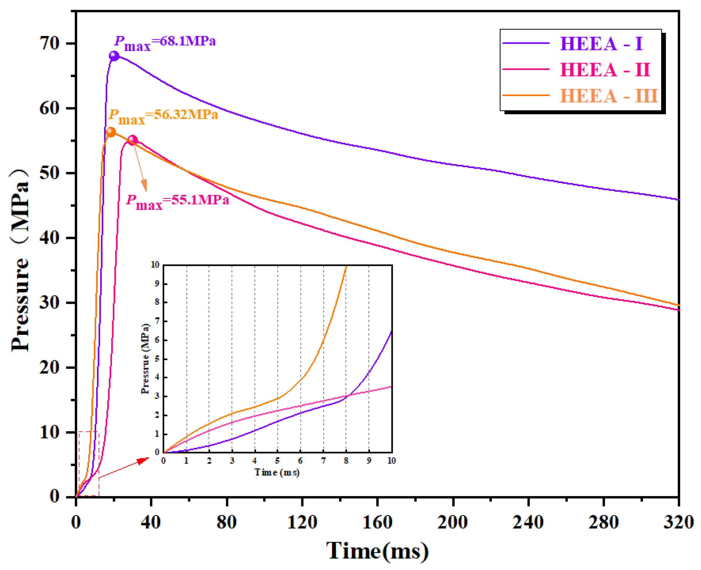
3.2. Explosion Pressure Law of High-Energy Expansion Agents

Figure 11 shows the P-t curve of HEEA tested in a 100 mL airtight explosive device. In a very short time after being ignited, HEEA rapidly detonates and reaches the maximum explosion pressure (Pmax) of about 20 ms. The Pmax of HEEA-I is 68.1 MPa, which is 19.01% and 17.3% higher than that of HEEA-II and HEEA-III, respectively. This is mainly due to the higher gas specific volume and more active molecular weight of HEEA-I. The difference in Pmax between HEEA-II and HEEA-III is small, which is mainly due to the relatively higher gas specific volume of HEEA-II, while the combustion heat of HEEA-III is higher, and the detonation products have higher internal energy. It can be seen that Pmax is mainly determined by the combined effect of the internal energy and volume of the explosive product.
The zoom-out in Figure 11 is the P-t curve over 10 ms of HEEA deflagration. At 0~4 ms, the explosion pressure of HEEA-II and HEEA-III is significantly higher than that of HEEA-I, showing strong initial deflagration performance. This is mainly affected by the heat of combustion. The higher combustion internal energy makes the explosion pressure of HEEA-II and HEEA-III rise faster. The initial explosion pressure curve of HEEA-I is relatively flat, because the initial deflagration internal energy of the sample is small, and the gas volume pressure efficiency is slow. With the accumulation of detonation gas, the explosion pressure of the sample jumps at 8 ms and reaches Pmax at 20.26 ms. At 5~6 ms, the explosion pressure of HEEA-III has a significant jump, which is mainly due to the high heat product of the sample intensifying the combustion reaction, inducing the rapid expansion of the detonation gas, and overcoming the influence of the low molecular weight of the gas to a certain extent, and reaches Pmax at 18.55 ms. The results show that the initial deflagration energy of HEEA with low calorie value and high gas specific volume is small, and the generated Pmax is large; the HEEA with high calorie value and low gas specific volume has large initial deflagration energy, and the generated Pmax is small, but the combustion rate is faster. The applied practice provides a theoretical basis.
As shown in Figure 12, compared with explosive blasting and HEEA blasting, HEEA action time is much longer. The action time of an explosive is microseconds, and the action time of HEEA is milliseconds, so it will form cracks with a large range and high complexity in the process of rock breaking. On the contrary, the action time of hydraulic fracturing is too long, the loading rate is low, the number of fractures formed is limited, and the fracture network cannot be effectively formed. However, the peak pressure of high-energy gas is high, and the pressure reduction rate is slow. Therefore, high-energy gas rock breaking has a broad prospect in the field of engineering blasting.

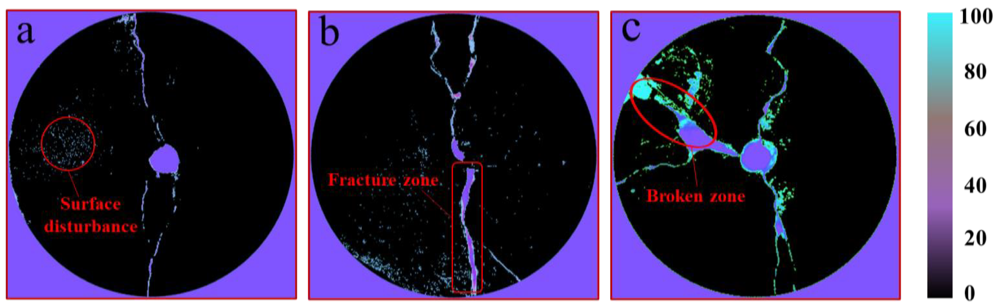
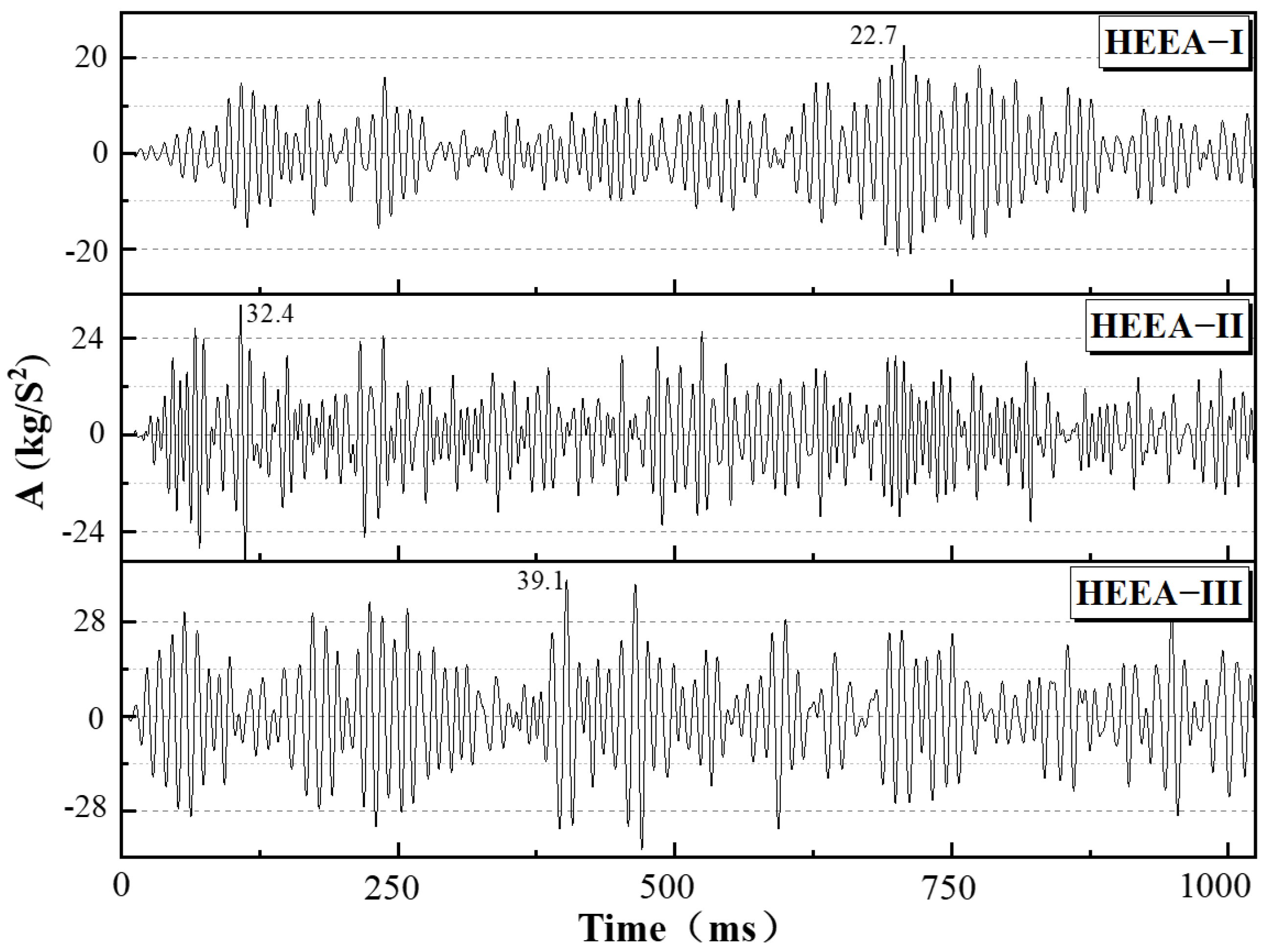
3.3. Damage Characterization of Rocks Fractured by High-Energy Expansion Agents

Figure 13 shows the damage characterization of the orifice surface of the HEEA-cracked concrete specimen. It can be seen that the main fracture zones of the three groups of specimens are all along the principal stress direction of the orifice. There are two main reasons for this phenomenon: one is that a large amount of heat and gas is accumulated near the orifice, resulting in thermal energy and stress mainly manifesting at the orifice position; the other is that during the initial drilling, disturbance damage is caused to the surrounding of the hole wall, and the high-heat and high-pressure gas preferentially spreads to the vulnerable area. Through comparative observation, it is found that the three types of HEEA caused different degrees of fracture to the specimen. Among them, part of the broken area appears on the upper left side of the specimen in Figure 13c, which is due to the high-temperature internal energy of HEEA-III. The stress of the specimen dropped sharply, and the disturbance to the specimen is more destructive, resulting in an obvious damage effect, indicating that the agent with high combustion heat and high combustion rate has a stronger rock-breaking ability. Combined with Figure 13a,b, the HEEA-I-damaged specimen has finer cracks, and the disturbance to the specimen is less destructive. The cracks of HEEA-II-damaged specimens are relatively regular and have good penetration. The results show that the high-temperature and high-pressure gas generated by the sample has an obvious damage effect, with the law that the rock fractured in the conditions of low heat and high gas specific volume has less disturbance and damage, and the rock fractured in the conditions of high heat and low gas specific volume has a large damage degree.
Figure 14 shows the acoustic emission signal curve of the concrete specimen during the damage process. During the process of the HEEA gas-induced specimen cracking, there are multiple oscillating signal peaks. This phenomenon can indicate that the process of HEEA cracking of the specimen is continuous, which is beneficial to the specimen being fully pre-cracked and damaged. In the early stage of deflagration, the HEEA with low calorific value and high gas specific volume is firstly subjected to small-scale pre-splitting of the rock. When the heat energy and gas are fully released, a relatively strong cracking process is carried out. Therefore, the maximum peak value of the oscillation signal of HEEA-I is significantly delayed, which has a positive effect on the further expansion and extension of the crack. In the initial stage of HEEA-II deflagration, several high peaks of oscillation occur, the amplitude intensity is up to 32.4 kg/s2, and the energy is continuously output with a high peak value of oscillation, which effectively ensures the stable expansion and development of cracks. The peak intensity of the maximum oscillating signal of HEEA-III is 39.1 kg/s2, but the continuity is not obvious. The above results further verify the damage characterization phenomenon of concrete specimens in Figure 10 and provide theoretical guidance for the flexible selection of HEEA engineering applications.

3.4. Damage Mechanism of Rock Cracked by High-Energy Expansion Agents

In the isentropic expansion process, the expansion work of the compressed gas cannot be completely converted into useful work, and the efficiency of converting the gas expansion work into useful work depends on the internal pressure of the gas and the pressure of the external environment where the gas is located. The higher the internal pressure of the gas and the lower the external environmental pressure, the higher the efficiency of converting the expansion work of the gas into useful work. The high-temperature and high-pressure gas generated by the combustion of HEEA inside the rock will generate expansion work on the specimen. When the compressive strength of the specimen is P1, the minimum work required to cause crack damage to the specimen is as shown in Equation (5). At the moment of rock damage, the required amount n1 and volume V1 of explosive gaseous substances are as shown in Equations (6) and (7). Because the process of high-temperature and high-pressure gas generated by HEEA combustion is short-lived, the specimen is completely pre-cracked and damaged in an instant. Therefore, when the cracking process is completed, the gas generated by the combustion of HEEA will no longer have a pre-cracking effect due to the pressure relief of the crack. It can be seen that in the limited rock, HEEA-II and HEEA-III have better fracturing rock performance by virtue of high internal energy; in particular, HEEA-III is more destructive. When in unbounded rock, HEEA-I promotes fracture extension and expansion due to high gas specific volume, and the performance of fractured rock will be more ideal.
W min = P 1 V 0
n 1 = P 1 V 0 R T 1
V 1 = P 1 V 0 P 0
where W min is the minimum work required for crack damage, P 1 is the minimum pressure, V 0 is the minimum gas volume, n 1 is explosive gas material, and V 1 is the volume of explosive gas.
From formula (3), it can be known that the amount of n2 gaseous substances produced by the complete combustion of HEEA is as shown in formula (8).
n 2 = P 0 V R T 0
It can be obtained that the work of the high-temperature and high-pressure gas generated by the combustion of HEEA has a maximum value Wmax, as shown in Equation (9).
W max = P 0 V T 0 T 1
HEEA burns stably in an open space, and its heat and gases are free to escape and be released. When a large amount of heat and gas builds up in an enclosed space, HEEA deflagrates. As the combustion reaction continues, the large amount of internal energy accumulated in the enclosed space causes the ambient pressure to increase sharply, and the HEEA changes from deflagration to detonation (DDT), as shown in Figure 15. The energy released by HEEA through combustion enters the primary fissure and produces the main fissure zone and the new fissure zone near the orifice. At the same time, part of the energy enters the fracture zone through the fractured rock and continues to expand and develop. When the fracture zone is connected to the external space, a part of the energy escapes and is released along the opening direction of the crack. It can be seen that the DDT reaction process occurs when HEEA burns in the rock, revealing the rock fracturing mechanism of HEEA from deflagration to detonation in a confined space and providing a theoretical basis for the engineering application of HEEA fracturing rocks.

4. Conclusions

In this study, the energy characteristics of HEEAs and the mechanism of fracturing rock were investigated. The energy parameters of combustion heat, gas volume, and detonation pressure of three types of HEEA were obtained by using a variety of testing methods, and the mechanism of HEEA cracking rock was revealed. The main conclusions are as follows:
(1) The calorific values of combustion of the three HEEAs are 2685.6 J/g, 3549.6 J/g, and 4212 J/g, respectively, which is mainly because of the high formation enthalpy of Al and Si. The work relation of three types of HEEA in a thermodynamic system is WHEEA-I < WHEEA-II < WHEEA-III. The gas specific capacity of HEEA-I is 513 L/kg, which is 60.31% and 153.96% more than that of HEEA-II and HEEA-III, respectively.
(2) The explosion pressures of HEEA-I, HEEA-II, and HEEA-III in the closed explosive device are 68.1 Mpa, 66.32 Mpa, and 55.1 Mpa, respectively. The Pmax of HEEA is mainly determined by the internal energy and volume of explosive products. An HEEA with low heat and high gas volume has small initial deflagration energy and large Pmax, while an HEEA with high heat and low gas volume has large initial deflagration energy and small Pmax, which provides a theoretical basis for the application of HEEAs.
(3) The damage effect of high-temperature and high-pressure gas cracking specimens generated by deflagration of HEEA is obvious, which has the rule that the disturbance damage of rock caused by low heat and high gas specific volume is smaller and the damage degree of rock caused by high heat and low gas specific volume is larger. The HEEA is ignited in a closed space. Due to the accumulation of a large amount of heat and gas, with the continuous combustion reaction, a large amount of internal energy accumulated in the closed space makes the ambient pressure increase sharply. This reveals the mechanism of the combustion and detonation of HEEAs in a closed space and provides a theoretical basis for the application of HEEA-cracked rock.

Author Contributions

Conceptualization, X.W.; Data curation, X.W.; Funding acquisition, Y.Z.; Methodology, L.C., J.S. and X.W.; Project administration, Y.Z.; Resources, Y.Z.; Software, L.C. and J.S.; Supervision, L.C.; Visualization, L.C.; Writing—original draft, X.W.; Writing—review & editing, Y.Z. All authors have read and agreed to the published version of the manuscript.

Funding

This work was supported by the National Natural Science Foundation of China (51974179).

Data Availability Statement

All data and materials generated or analysed during this study are included in this published article.

Conflicts of Interest

The authors declare no conflict of interest.

References

  1. Wang, H.; Cheng, Z.; Zou, Q.; Li, Z.; Sun, F.; Yang, H.; Lei, Y. Elimination of coal and gas outburst risk of an outburst-prone coal seam using controllable liquid CO2 phase transition fracturing. Fuel 2021, 284, 119091. [Google Scholar] [CrossRef]
  2. Lu, W.; Chen, M.; Geng, X.; Shu, D.; Zhou, C. A study of excavation sequence and contour blasting method for underground powerhouses of hydropower stations. Tunn. Undergr. Space Technol. 2012, 29, 31–39. [Google Scholar] [CrossRef]
  3. Onederra, I.A.; Furtney, J.K.; Sellers, E.; Iverson, S. Modelling blast induced damage from a fully coupled explosive charge. Int. J. Rock Mech. Min. Sci. 2013, 58, 73–84. [Google Scholar] [CrossRef]
  4. Dai, F.; Li, B.; Xu, N.; Zhu, Y. Microseismic early warning of surrounding rock mass deformation in the underground powerhouse of the Houziyan hydropower station, China. Tunn. Undergr. Space Technol. 2017, 62, 64–74. [Google Scholar] [CrossRef]
  5. Wang, H.; Li, G.; Shen, Z.; Tian, S.; Sun, B.; He, Z.; Lu, P. Experiment on rock breaking with supercritical carbon dioxide jet. J. Pet. Sci. Eng. 2015, 127, 305–310. [Google Scholar] [CrossRef]
  6. Zhuang, L.; Zang, A. Laboratory hydraulic fracturing experiments on crystalline rock for geothermal purposes. Earth-Sci. Rev. 2021, 216, 103580. [Google Scholar] [CrossRef]
  7. Yuan, W.; Wang, W.; Su, X.; Li, J.; Li, Z.; Wen, L.; Chang, J. Numerical study of the impact mechanism of decoupling charge on blasting-enhanced permeability in low-permeability sandstones. Int. J. Rock Mech. Min. Sci. 2018, 106, 300–310. [Google Scholar] [CrossRef]
  8. Li, Z.; Yu, S.; Zhu, W.; Feng, G.; Xu, J.; Guo, Y.; Qi, T. Dynamic loading induced by the instability of voussoir beam structure during mining below the slope. Int. J. Rock Mech. Min. Sci. 2020, 132, 104343. [Google Scholar] [CrossRef]
  9. Shang, J.; Zhao, Z.; Aliyu, M.M. Stresses induced by a demolition agent in non-explosive rock fracturing. Int. J. Rock Mech. Min. Sci. 2018, 107, 172–180. [Google Scholar] [CrossRef]
  10. Cao, Y.; Zhang, J.; Zhai, H.; Fu, G.; Tian, L.; Liu, S. CO2 gas fracturing: A novel reservoir stimulation technology in low permeability gassy coal seams. Fuel 2017, 203, 197–207. [Google Scholar] [CrossRef]
  11. Li, Q.Y.; Chen, G.; Luo, D.Y.; Ma, H.P.; Liu, Y. An experimental study of a novel liquid carbon dioxide rock-breaking technology. Int. J. Rock Mech. Min. Sci. 2020, 128, 104244. [Google Scholar] [CrossRef]
  12. He, Y.; Flynn, S.L.; Folkerts, E.J.; Zhang, Y.; Ruan, D.; Alessi, D.S.; Martin, J.W.; Goss, G.G. Chemical and toxicological characterizations of hydraulic fracturing flowback and produced water. Water Res. 2017, 114, 78–87. [Google Scholar] [CrossRef]
  13. Luek, J.L.; Gonsior, M. Organic compounds in hydraulic fracturing fluids and wastewaters: A review. Water Res. 2017, 123, 536–548. [Google Scholar] [CrossRef]
  14. Zhigach, A.N.; Leipunskii, I.O.; Pivkina, A.N.; Muravyev, N.V.; Monogarov, K.A.; Kuskov, M.L.; Afanasenkova, E.S.; Berezkina, N.G.; Pshechenkov, P.A.; Bragin, A.A. Aluminum/HMX nanocomposites: Synthesis, microstructure, and combustion. Combust. Explos. Shock Waves 2015, 51, 100–106. [Google Scholar] [CrossRef]
  15. Yan, T.; Ren, H.; Liu, J.; Jiao, Q. Facile preparation and synergetic energy releasing of nano-Al@RDX@Viton hollow microspheres. Chem. Eng. J. 2020, 379, 122333. [Google Scholar] [CrossRef]
  16. Sun, H.; Li, X.; Wu, P.; Song, C.; Yang, Y. Preparation and Properties of RDX/Aluminum Composites by Spray-Drying Method. J. Nanomater. 2020, 2020, 1083267. [Google Scholar] [CrossRef]
  17. Hu, H.; Chen, L.; Yan, J.; Feng, H.; Xiao, C.; Song, P. Effect of Aluminum Powder on Underwater Explosion Performance of CL-20 Based Explosives. Propellants Explos. Pyrotech. 2019, 44, 837–843. [Google Scholar] [CrossRef]
  18. Li, X.; Pei, H.; Zhang, X.; Zheng, X. Effect of Aluminum Particle Size on the Performance of Aluminized Explosives. Propellants Explos. Pyrotech. 2020, 45, 807–813. [Google Scholar] [CrossRef]
  19. Kuznetsova, N.; Zhgun, D.; Golovanevskiy, V. Plasma blasting of rocks and rocks-like materials: An analytical model. Int. J. Rock Mech. Min. Sci. 2022, 150, 104986. [Google Scholar] [CrossRef]
  20. Cui, S.; Liu, S.; Li, H.; Zhou, F.; Sun, D. Critical parameters investigation of rock breaking by high-pressure foam fracturing method. Energy 2022, 258, 124871. [Google Scholar] [CrossRef]
  21. Wang, J.; Elsworth, D.; Cao, Y.; Liu, S. Reach and geometry of dynamic gas-driven fractures. Int. J. Rock Mech. Min. Sci. 2020, 129, 104287. [Google Scholar] [CrossRef]
  22. Yan, H.; Zhang, J.; Li, B.; Zhu, C. Crack propagation patterns and factors controlling complex crack network formation in coal bodies during tri-axial supercritical carbon dioxide fracturing. Fuel 2021, 286, 119381. [Google Scholar] [CrossRef]
  23. Deng, B.; Yin, G.; Li, M.; Zhang, D.; Lu, J.; Liu, Y.; Chen, J. Feature of fractures induced by hydrofracturing treatment using water and L-CO2 as fracturing fluids in laboratory experiments. Fuel 2018, 226, 35–46. [Google Scholar] [CrossRef]
  24. Wu, Q.; Ma, Q.; Zhang, Z.; Yang, W.; Gou, S.; Huang, J.; Fan, G. Combustion and catalytic performance of metal-free heat-resistant energetic polymeric materials. Chem. Eng. J. 2020, 399, 125739. [Google Scholar] [CrossRef]
  25. Ye, R.; Yu, Y.G.; Cao, Y.J. Analysis of Micro-scale Flame Structure of AP/HTPB Base Bleed Propellant Combustion. Def. Technol. 2013, 9, 217–223. [Google Scholar] [CrossRef]
  26. Zha, K.; Florea, R.; Jansons, M. Soot Evolution with Cyclic Crank-angle-resolved Two-color Thermometry in an Opti-cal Diesel Engine Fueled with Biodiesel Blend and ULSD. J. Eng. Gas Turbines Power 2012, 88, 1620–1628. [Google Scholar]
  27. Wu, F.; Wei, X.; Chen, Z.; Rahman, S.S.; Pu, C.; Li, X.; Zhang, Y. Numerical simulation and parametric analysis for designing High Energy Gas Fracturing. J. Nat. Gas Sci. Eng. 2018, 53, 218–236. [Google Scholar] [CrossRef]
Figure 1. Schematic diagram of vertical screw mixer.
Energies 15 07156 g001
Figure 2. Hartmann flame propagation test device.
Energies 15 07156 g002
Figure 3. Structural diagram of automatic oxygen bomb calorimeter.
Energies 15 07156 g003
Figure 4. Structural diagram of calorimetric elastic gas specific volume test device.
Energies 15 07156 g004
Figure 5. Closed bomb test device.
Energies 15 07156 g005
Figure 6. Test device for presplitting and crushing of concrete specimen.
Energies 15 07156 g006
Figure 7. FE-SEM characterization of high-energy expansion agent.
Energies 15 07156 g007
Figure 8. Particle size distribution of high-energy expansion agent admixture.
Energies 15 07156 g008
Figure 9. Combustion heat and gas specific volume of high-energy expansion agent.
Energies 15 07156 g009
Figure 10. Flame characteristics and temperature distribution of high-energy expansion agent.
Energies 15 07156 g010
Figure 11. P-t curve of high-energy expansion agent admixture.
Energies 15 07156 g011
Figure 12. P-t curves of three typical fracturing forms.
Energies 15 07156 g012
Figure 13. Characterization of damage degree of orifice surface of concrete specimen. (a) Characterization of presplitting rock of HEEA-I. (b) Characterization of presplitting rock of HEEA-II. (c) Characterization of presplitting rock of HEEA-III.
Energies 15 07156 g013
Figure 14. Acoustic emission signal curve of concrete specimen in damage process.
Energies 15 07156 g014
Figure 15. Mechanism of high-energy expander combustion and rock breaking.
Energies 15 07156 g015
Table 1. Mass ratio of high-energy expansion agent admixture components.
ComponentOxidantFuelCombustion RegulatorAdhesivePlasticizer
HEEA-IKClO4 (50.9%)C-powder (4.4%)
CH6N4O3 (42.7%)
Cu2Cr2O5 (1.5%)HTPB (1%)C26H50O4 (1.5%)
HEEA-IIKClO4 (68.1%)Si-powder (27.9%)Cu2Cr2O5 (1.5%)HTPB (1%)C26H50O4 (1.5%)
HEEA-IIIKClO4 (64.8%)Al-powder (31.2%)Cu2Cr2O5 (1.5%)HTPB (1%)C26H50O4 (1.5%)
Table 2. Mechanical parameters of concrete specimens.
Test SpecimenDensity
(g/cm3)
Uniaxial Compressive Strength (MPa)Uniaxial Tensile Strength (MPa)Elastic Modulus (GPa)Poisson’s RatioInternal Friction Angle (°)Cohesion
(MPa)
Concrete2.342.65.213.60.1234.872.8
Publisher’s Note: MDPI stays neutral with regard to jurisdictional claims in published maps and institutional affiliations.

