Abstract
The contact problem of a trochoidal gear is a drawback and a well-known performance indicator of a gerotor pump. Although numerical simulations aid in the evaluation of contact stress, the difficult task of determining geometrical parameters, operating conditions, and the number of simulations to run falls to the designer. This paper presents the Taguchi techniques as an effective simulation-based strategy to narrow down the geometrical parameter combinations, reducing the solution space and optimizing the number of simulations. The work is first focused on the validation of the proposed numerical model by means of published contact stress results of recognized researchers in the field, as well as the unification of nomenclature and notation. Then, the Taguchi approach is based on a sequence of four experiments, ranging from the screening case with two levels and seven parameters to multiple levels and four parameters with three software input operating conditions (temperature, torque, and friction coefficient) emulating noise effects. The contact stresses of 128 gear sets, having common volumetric capacity and dimensional constraints to detach mechanical performance from flow rate and casing, were analyzed. Results prove the feasibility of the proposed methodology by identifying the most suitable gear set configuration and predicting the quantifiable performances of a real-working gerotor pump.
1. Introduction
Fluid technology, as a part of human activities, has become one of the important issues in connection with environmental concerns. Hydraulic machines play an essential role in fluid technology and will further accelerate their green transition in the coming years with the improvement of models and simulations [1]. The gerotor pump is intended to be a part of the solution in leading research technologies in industrial and aeronautical areas, mechanical engineering, pharmacy, medicine and, more recently, in areas such as the design of a virtual prototype to be used in the context of a Digital Twin tool [2].
Nowadays, attention has been focused on reducing energy loss and improving efficiency, since any relatively small proportion of them is becoming crucial in any technology. Improvement of electric consumption, heralded as the critical step in the reduction of transportation’s impact on climate change, can be used as an example in the adapted Figure 1 from the work of Kawamata et al. [3]. Loss due to friction in the motor-based drive system of an electric vehicle (EV) system is still responsible for approximately 10% of the total global energy consumption. Loss due to aerodynamics is the most important factor of an EV during operation compared with an internal combustion engine (ICE), but there is still room for improving the current levels of energy consumption by paying attention to these slight proportions as loss due to friction.
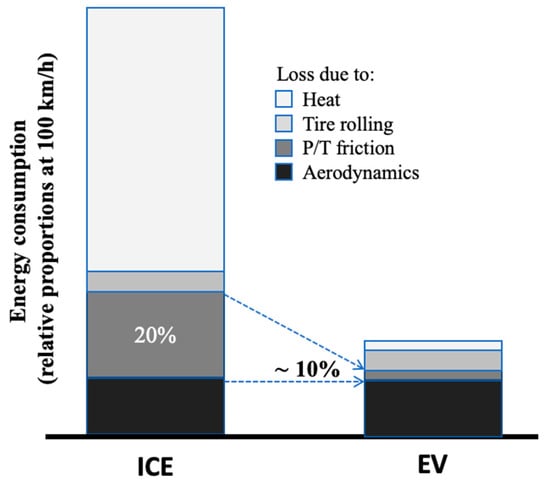
Figure 1.
Comparison of energy consumption loss between ICE vehicle and EV (adapted from Kawamata et al. [3]).
Contact stresses and friction are key performance indicators of a trochoidal gear set working as a gerotor pump. Over the years, from the work on the reduction in contact stress in internal gear pumps by Colbourne [4] in 1976 up to recent works such as gap estimation in ORBIT motors by Roy et al. [5,6] and the in-depth design concept of hydraulic displacement units by Sliwinski [7], an important body of literature has been published related to contact, deformation, clearance, and stress in the teeth of gerotor pumps. In fact, “contact” and “stress” appeared among the top ten keywords in the list of the thirty most frequently used keywords in the publications from 2009 to 2019 [8].
It should be pointed out that two researchers, Ivanović and Biernacki, have conducted remarkable contact stress studies on gerotor pumps over the last twelve years. Ivanović and the colleagues have explored this challenging area in analytical methods [9,10,11], wear rate, friction, and stress index evaluation [12,13,14,15,16]. Biernacki and the colleagues have investigated the field with an emphasis on new materials [17,18,19,20,21] and new concepts of design [22,23]. Both research groups have stood out and exceled in the area.
When the question of how to choose the gear set to improve performance indexes arises, optimization has come to assist. Focusing on works of the past five past years, Robinson and Vacca [24,25] and De Martin et al. [26] have published complete studies in multi-objective optimization to traditional circular-toothed profiles. As a result, the procedure pinpointed that the industry was able to find optimal solutions at almost the same level as the state-of-the-art pump designs. A thorough study of commercial gear sets of a company carried out by Tessari et al. [27] and Pulliti et al. [28] allowed them to extrapolate an empirical formulation for the eccentricity, the initial parameter of the optimization strategy to maximize volumetric efficiency.
Whenever the question of how to choose the geometrical parameters to design a new-born trochoidal gear pump comes up, the answer is not straightforward and an intermediate step amid the proceedings from academia and industry, between commercial gear sets and optimization procedures, would be especially welcome. In addition, the designer’s goal is not only to reduce the time and effort to set up the analysis, but also to diminish and even remove the various costs associated with conducting any trial. Hence, numerical simulation comes as a design aid. A new numerical simulation may confront a new set of issues, such as how to evaluate the parameters, how many numerical simulations to carry out, how to estimate parameter combinations, or how to link mechanical and fluid-dynamic characteristics. The purpose of this paper is to attempt to address the above researcher’s questions from a practitioner’s perspective and the Taguchi method is chosen to blend knowledge from commercial gear sets to numerical simulations. Another important advantage of the Taguchi method is its accessibility to any end-user, becoming an open tool not restricted by software.
The Design of Experiments (DoE) is a well-known and powerful tool [29]. The DoE process is divided into three main phases as follows: (1) the planning phase: factors and levels are selected, (2) the conducting phase: test results are collected, and (3) the analysis phase: positive or negative information concerning the selected factors and levels is generated based on phase (1) and (2). A full-factorial experiment, having an equal number of test data points under each level of each factor, is acceptable when only a few factors are to be investigated, but not very advisable when there are many factors [30].
The Taguchi approach is a holistic view based on the use of orthogonal arrays (OA) to conduct small, highly fractional factorial experiments up to larger, full-factorial experiments [31]. An alternative approach could be the use of Monte Carlo simulation, but it requires a large number of testing conditions for an accurate estimation of the mean and variance, which is expensive and time-consuming [29,32]. Each OA has a determined maximum possible resolution [33]. The selection of which OA to use predominantly depends on (in order of priority): (i) the number of factors and interactions of interest, (ii) the number of levels for the factors, and (iii) the desired experimental resolution or cost limitations. This strategy will minimize the total number of tests to be conducted yet will yield meaningful information at the same time. A lack of communication between the academics and specialists in industrial worlds is a cause that has restricted the application of the Taguchi method on a larger scale [34]. To analyze the data and determine the optimum levels of selected factors, the signal-to-noise (S/N) ratio was developed by Dr. Taguchi as a performance measure to choose control levels that best cope with noise effects. All these uncontrolled and unknown factors that actually vary from one degree to another, causing differences from data point to data point, generate noise effects. Rather than assuming that error variation is an aggregate of all these noise effects and equally distributed in all treatment conditions, Taguchi parameter design utilizes these repetitions to aid in identifying what levels of which control factors might have reduced variation.
To varying degrees of depth, the Taguchi method has been applied to volumetric characteristics in a gerotor pump. Jung et al. [35] implemented the method for the design of lobes with multiple profiles. The optimal design parameters obtained are promising in the experimental results of volumetric performance, but unfortunately, the explanation of the implementation is scarce and noise effects are not mentioned. Ivanović et al. studied the selection of optimal parameters for the volumetric characteristics of a gerotor pump, such as flow rate and volumetric efficiency, through a factorial design and response surface methodology [36] and by using the Taguchi method [37]. Three tested geometries at three different rotation speeds and pressures were established as influential parameters. In these experimental works, a selection of noise factors is not reported. As a result, one important contribution of the presented work is the use of several input parameters as noise factors to assess the contact stress characteristics in a gerotor pump.
The application of the Taguchi method in software and computer design has been reported. As an example, assistance for the management of defects found in software development by quantifying performance has been proven [38]. The multitude of parameters in Computer Aided Design (CAD) and Computer Aided Manufacturing (CAM) are also benefited by the structured generation of a representative subset of them into a solution space, as is shown in bevel gear machining simulations [39]. The mechanical performance can be modeled mathematically by using the finite element methodology, which makes the contact stress a prime candidate for designed experiments using the environment of the software packages. Choudhury et al. [40] demonstrated the feasibility of this approach by working with the mechanical design of an epicyclic gear train to find an optimized set of various input factors for which the stresses are the lowest and, thus, the chances of tooth failure are reduced. The simulated experiments can use the operating conditions to emulate noise effects (prescribed factors in the software) in an outer array, in combination with an inner array for only control factors (controllable parameters in the simulation). Hence, the use of the Taguchi method in numerical simulation to assess the contact stress characteristics of a gerotor pump is the other key contribution in the present research.
The methodology in this work follows three consecutive phases to achieve the goals: the background of a trochoidal gear set, the verification of the contact stress numerical simulation, and the Taguchi approach to a gerotor pump. Establishing the right blueprint is a challenge unique to each phase. The first phase establishes the basic definition of a trochoidal profile, the function of a gerotor pump, the selected gears from the literature under study, the geometry generation, and the integration of nomenclature and notation.
The second phase aims to build a solid foundation on which the implementation of the Finite Element Model (FEM) to evaluate contact stresses is supported by verification. Hence, a set of simulations, along with their geometries, have been selected and extracted from the literature, and the fundamental criterion was to be able to reproduce the results since not all published articles provide the necessary technical data. The objective of this approach is to reconstruct those simulations and corroborate the validity of the results within reasonable bounds.
Once the outcomes are verified, the last phase involves a sequential simulation-based design strategy of four Taguchi experiments turning out 128 numerical simulations: from the screening case with two levels and seven parameters up to multiple levels and four parameters with three noise factors. This innovative approach to the Taguchi method is the study of the contact stress by using a software package that is feasible to emulate noise effects as input operating data for a set of gerotor geometries that have in common a constant volumetric capacity and dimensional constraints. Hence, the outer noise (environmental-related, such as temperature) and inner noise (function-related, such as torque and friction coefficient) retain significance with the noise effects of the Taguchi method.
This paper endeavors to prove the reliability of the proposed methodology to predict optimum settings in the geometry of gerotor pumps and be able to find gear sets in industrial designs. This study looks to formulate its own approach that identifies the most suitable gear set configuration and predicts the quantifiable performance of a real-working gerotor pump, taking into account best practices in the design process to guide the designer to make good decisions in the numerical simulation procedure.
2. Trochoidal Gear Set Background
A trochoidal gear set is a pair of gears, inner/internal and outer/external, with trochoidal tooth profiles (see Figure 2 and check the Nomenclature section). The two gears are mated so that each tooth/lobe of the internal gear is always in sliding contact with a tooth of the external gear, and inter-tooth contact occurs. These points are known as contact points. The pumping action is generated since the volume trapped between two consecutive contact points varies, increasing and decreasing with the angular position of the mated gears. This internal gear pump is well-known as the gerotor pump. For the sake of simplicity, and because they can be found thoroughly in the literature, theoretical analysis and formulae are not explicitly presented in this work; as a reference, see work [41].
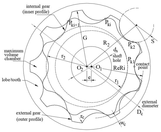
Figure 2.
Basic geometric parameters of the trochoidal gear set.
2.1. Gear Sets under Study
Works from the literature were selected to validate the implemented numerical model. The main criterion of election was that selected works should contain numerical mechanical analyses, including an evaluation of the contact stress level. In addition, the researchers of these selected works ought to have a long and solid career in the mechanical analysis of trochoidal gear sets and gerotor pumps. Hence, the researchers Ivanović and Biernacki fulfil more than enough of the above-mentioned selection criteria, and their studies selected have been [13,14,17,23], respectively. In addition, a reference geometry with theoretical, numerical, and experimental work is also added to the study [42].
The codification used in the present study to unify all gear sets follows the same sequence as Per___: PZXeYYY. X is a figure coding the number of teeth of the outer gear and YYY are three figures coding the non-decimal eccentricity value of the gear set (the three digits without the decimal dot). This codification is illustrated in Table 1, along with supplementary information.

Table 1.
Gear sets under study (PZXeYYY, where X is the number of teeth of the outer gear and YYY are the non-decimal eccentricity value).
2.2. Nomenclature and Notation
Nomenclature and notation of the basic geometric parameters are not standardized, and each researcher uses their own. The present study works with the GeroLAB notation [43], then the researchers’ geometries under analysis are contextualized in this specific nomenclature and presented in Table 2.
Table 2.
Geometrical and technical parameters of gear sets (please refer to Nomenclature section and Figure 2).
2.3. Geometry Generation
Once basic geometrical parameters are decoded, as presented in Table 2, the full set of trochoidal gears has to be generated. The well-known formulae for calculating the trochoidal profiles of a gear set can be used by introducing these geometrical parameters into specialized free software, such as GeroLAB (Terrassa, Spain) [44], which will calculate and provide the technical drawings in CAD format. By importing the drawing into CAD software (Vélizy-Villacoublay, France), a planar body of the geometry is created and modified with the appropriate operations, such as splitting, adding, and assembling, to be able to be imported into a mechanical simulation software.
3. Verification of Contact Stress Numerical Simulation
3.1. Numerical Model Definition
Two main series of numerical simulations are considered. The first one is aimed at validating the implemented Finite Element Model (FEM) and consists of simulating real cases of gerotor systems published in the literature, which include mechanical data. The second series is aimed at analyzing the influence of different parameters according to the Taguchi method.
All simulations are run in ANSYS® 19.2R (Canonsburg, PA, USA). This general-purpose software environment was selected because of its wide availability among practitioners and also because most of the definitions in terms of mechanical description are analogous and comparable to those of other FEM simulation packages. Moreover, the multiphysics capability of ANSYS® would allow future enhancement of the model applicability including fluid or thermal transitive simulations, although these steps are far beyond the aim of the current research. In addition, many other researchers have used this software package to study gear contact stresses before, such as Ram Kumar et al. [45], Karthick et. Al. [46], Benaïcha et al. [47], Rao [48], Lahtivirta and Lehtovaara [49], or Lisle et al. [50]. The most relevant information about the implemented numerical models is described in the following subsections.
3.1.1. Geometry and Material Properties
The geometry in all cases consists of two parts: the internal and the external gear. For every reference case, two angular positions of the gear sets are simulated: 0⁰ and 25⁰. One additional case at 40⁰ is considered for the PZ9e285 case. The keyway is not allocated in any geometry. Hence, since two specific positions in the gear set are only required, the Static Structural module is the most suitable selection.
Despite the fact that all the simulations chosen from the literature share common characteristics, two of them are computed with a 3D geometry. On the one hand, the specific reasons why these researchers decided to implement 3D are unknown. On the other hand, although these simulations were run in 3D, the results are shown in 2D, in the front plane of the gear sets. Then, this fact endorsed the decision to assume a 2D plain stress hypothesis with gear thickness as input data in this study. Two main advantages are added: the remarkable diminution of mesh elements and the contact definition as edge–edge and not surface–surface, which helps the program to be more precise.
For all simulations, isotropic linear elastic material is considered. Thus, the only properties required for the numerical simulation are Young’s modulus and Poisson’s and friction coefficients (see Table 2).
3.1.2. Loads, Contacts, and Boundary Conditions
The boundary conditions consist of fixing the edge of the external diameter of the external gear and imposing a restrained and fixed displacement on the edge of the shaft hole of the internal gear, while allowing its rotation. The load is performed by a counter-clockwise torque applied on the edge of the shaft hole of the internal gear. For the validation cases, the value of the torque is set according to the corresponding reference in the researchers’ works.
Finally, contacts are described as frictional through the friction coefficient definition. All contacts are set between the specific edges of the teeth (internal and external) in interaction. Thus, it is required to divide the continuous internal and external edges in the trochoidal tooth profiles into as many parts as the corresponding number of teeth. This definition is essential to correctly set the contact areas to allow an independent analysis of the several contact points at the same time between gears: the quasi-static condition.
Using frictional contact rather than frictionless is preferred because it more accurately denotes real cases and allows one to study the possible life-long variation of the friction coefficient as an external factor on the contact stress, which is addressed later. Frictional contacts [5,51] and frictionless contacts [49,50] are both previously used by other researchers in gear contact studies.
3.1.3. Elements and Mesh
PLANE183 elements are used to mesh both internal and external gears. CONTA172 and TARGE169 elements are used to define the contacts. The average size of the mesh is 5 mm. This dimension is reduced to an edge sizing of 1 mm near the contact areas by imposing this seeding distance on the edges that define the contacts. Since the goal is to validate the model by obtaining results akin to the researchers’ work, an equivalent configuration must be used. The quality of the mesh is checked with the orthogonal quality indicator, with an average value of over 0.9, and also with the skewness indicator, with an average value of below 0.3, for all cases. Those indicators fulfilled the recommended quality mesh requirements in [52].
3.1.4. Analysis
The full Newton–Raphson solution procedure is employed to perform the implicit calculation of the implemented non-linear model. Average solution time is approximately ten minutes in an Intel® Core ™ i7-9700 K CPU @ 3.60 GHz with 16 GB RAM memory.
The use of equivalent von Mises stress is widely accepted and used in several research studies [45,46,47,48], although some of the research [51] points out that von Mises stress values could be approximately one half of the theoretical Hertz contact stress. In any case, the proposed model is validated through comparison with other accepted models that used von Mises’s stress. Finally, the influence of the analyzed parameters is also studied in terms of maximum von Mises’s stress at contacts, being mostly a comparative than a quantitative analysis.
3.2. Simulation Results: Validation and Discussion
The FEM validation aims to assess the recreated authors’ results from the researchers’ works aforementioned. If the validation is positive, meaning that the values obtained with the simulations match those published within reasonable bounds, the methodology will prove to be valid for future simulations using the same model applied up to here.
The maximum equivalent von Mises stress among all contact zones is the variable for comparison with reference stresses. Figure 3 graphically gathers authors’ FEM results of maximum contact stress in each gear set from researchers’ works at two angular positions, 0° and 25° (the angular position of each gear set in the researcher’s reference). A worthwhile comparison of results could have come from the deformation performance of the gear sets. However, limited information is available in the available literature and, consequently, it was decided to concentrate on contact stress results, which are the ultimate goal.
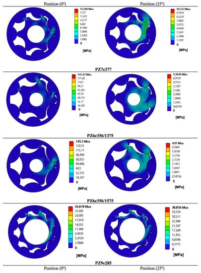
Figure 3.
Authors’ FEM results of maximum contact stress [MPa] in each gear set from researchers’ works at 0° and 25° angular positions. (The commas in this specific figure represents decimal dots. For interpretation of the references to color in this figure legend, the reader is referred to the Web version of this article.).
For the PZ9e285(25°) case, the mesh convergence analysis was performed obtaining the results plotted in Figure 4. The figure shows a clear contact stress value trend when reducing the contact edge sizing from 5 mm (11.5% variation) to 2 mm and from 2 mm (0.4% variation) to 1 mm. However, for smaller mesh sizes (0.50 mm and 0.25 mm), local stress concentration effects were observed to increase the maximum contact stress in a fictitious way. Thus, 2 mm edge size was precise enough to carry out the research, but 1 mm was chosen because it was more precise and was not a significantly greater calculation effort than the 2 mm case. For a 1 mm mesh size case, the PZ9e285 model included 7164 nodes, 2218 2D elements, and 420 contact elements.
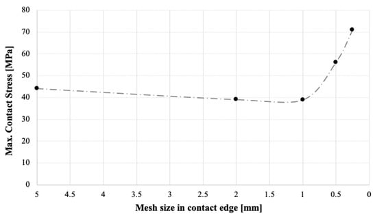
Figure 4.
Mesh convergence analysis of PZ9e285(25°) case.
The main results of the nine simulations are summarized in Figure 5. When researchers’ and authors’ results are contrasted at the maximum contact stress, a 9% average error is obtained when the PZ9e285(0°) is not included (this specific angular position of this gear set shows an unexpected value, and it is considered an outlier because clear stress concentration effects were detected in this case. In fact, a 40° position was also simulated to check the stability of the PZ9e285 case and to overcome this limitation). Since there is a restricted amount of available information about mechanical stresses in gerotors, this accuracy is judged to be adequate to validate the implemented model for describing the mechanical response of gerotor sets.
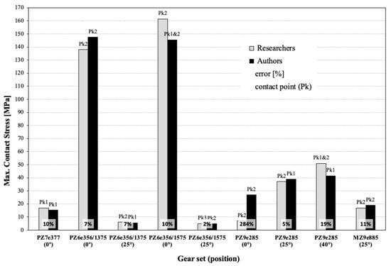
Figure 5.
Results comparison Researchers vs. Authors, relative error [%] in maximum contact stress [MPa] and contact point (Pk) of maximum contact stress in each gear set for corresponding angular position in brackets (degree °).
With regard to the location of the contact point at maximum stress, two clear tendencies can be pointed out:
- Maximum volume chamber position corresponding to PZ7e377(25°), PZ6e356/1375(0°), PZ6e356/1575(0°), and PZ9e285(0°). The location of the contact point at maximum stress is Pk2 for all gear sets, according to researchers’ and authors’ results. (Note: PZ7e377(25°) gear set in reference [17] does not provide an exact value but it can be gathered from the graphical figures);
- Minimum volume chamber position corresponding to PZ7e377(0°), PZ6e356/1375(25°), PZ6e356/1575(25°), PZ9e285(25°), and MZ9e885(25°). The location of the contact point at maximum stress are Pk and Pki + 1 for all results, researchers’ and author’s, respectively. The exceptions are PZ7e377(0°) and MZ9e885(25°).
Hence, it reveals the importance of having either an odd or even number of external gear teeth in the set-up of the simulation. In addition, the impossibility of simulating exactly the same geometries as the researchers must be remembered, as does how the unnecessary parts of the original geometry were neglected, such as the keyway in the shaft hole.
From these results, the plausibility of the proposed FEM model of the authors is sustained, as well as providing an opening for making progress toward the Taguchi approach. This decision is also justified by the fact that the final purpose of the implemented model is to study the significance and influence of the different design and environmental variables on the contact stress level more than providing a completely accurate result of the stress value.
4. The Taguchi Approach to a Gerotor Pump
The aim of parameter design outlined by Dr. Taguchi is to obtain a gear set that maximises the safety factor (SF) defined as the ratio between the reference yield strength of the material and the maximum contact stress. This gear set will be pursuing a twofold goal of (i) detaching the linkage of contact stress with volumetric capacity and dimensional constraints and (ii) enhancing the quality of contact stress assessment without controlling or removing the cause of variation contributed to by the numerical simulation’s input settings to generate robust FEM results against noise effects. This approach is an iterative process that will be carried out sequentially in four experiments. The means to achieve a certain average contact stress will not be addressed. The Minitab® 19 software package (State College, PA, USA) complements the data processing.
4.1. The Volumetric Capacity Target and the Dimensional Constraints of the Gerotor Pump
Volumetric characteristics and contact stress performance of a gerotor pump are linked by the geometric parameters [53]. Then, in order to soften this link, the contact stress, the volumetric capacity, and several dimensional constraints of the gerotor pump are fixed constants in each gear set for all experiments as follows:
- The PZ9e285 gear set is the chosen prototypical gerotor because it is well-known by the authors regarding, among others, its fluid dynamic performance [54];
- The benchmark gerotor is named D80d40cv1 and the parameters to keep constant are summarized in Table 3 and depicted in Figure 6 based on [55];
Table 3. D80d40cv1 benchmark gerotor. (Please refer to Nomenclature section and Figure 2).
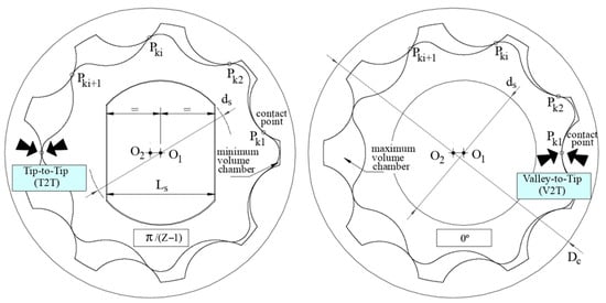 Figure 6. The benchmark gerotor in working function: the Tip-to-Tip (T2T) position (left) and the Valley-to-Tip (V2T) position (right), the shaft keyway (‘yes’ shaft keyway, left) and the shaft hole without keyway (‘no’ shaft keyway, right).
 - The material properties remain unchangeable in all the experiments: Young’s module, density, and Poisson’s coefficient of the PZ9e285 gear set (refer to Table 2);
- The shaft keyway is designed with dimensions Ls = 30 mm (parallel 0.75·ds) shown in Figure 6 as in [55];
- Two specific angular positions as working functions will be under the study: Tip-to-Tip (T2T) and Valley-to-Tip (V2T), both depicted in Figure 6. The V2T corresponds to the maximum volume chamber and the T2T corresponds to the minimum volume chamber. This labeling presumes to enhance the comprehension of the contact points’ action;
- The geometries and the analytical values of volumetric capacity and flow irregularity of each experimental gear set are provided by using GeroLAB [43,44].
4.2. The Taguchi Method: The Designed Experiments
The designed experiments by the Taguchi approach will follow these specific features:
- The number of control factors. The number of parameters is chosen based on the trochoidal gear profile (Z, e, S), external gear (rc, wc), and working function (reference position RP, shaft keyway SK);
- The number of levels. The levels of each parameter are chosen to be significant in the study, from the benchmark gerotor, the literature, the previously presented FEM validation, and the authors’ know-how. In addition, all level combinations have to accomplish the feasible geometry of a trochoidal gear set practicable to be generated with GeroLAB, which has become a challenging task. The number of levels is selected as the Taguchi approach is going forward, from two-levels to a mixed-level design;
- The noise factors. The mechanical operating conditions of the gear pump are described by three factors: material temperature (θ), torque (T), and material friction coefficient (µ), which can be tuned by surface modification methods [56,57]. The designed experiments can use these operating conditions as the input of FEM conditions as prescribed by an outer array only for noise factors (T, µ and θ);
- Improve the quality of contact stress assessment. The goal of the experiments is to maximize the safety factor (SF) as the response of the signal-to-noise ratio (S/N) set to Higher-is-Better (HB) where:where n = the number of tests in a trial (number of repetitions regardless of noise levels) and yi = each observed value (data points). In all cases, the target is to maximize the HB S/N ratio. The development of a family of matrices based on orthogonal arrays (OA) and the signal-to-noise (S/N) definition as an indicator of the ratio of the mean to the standard deviation are great contributions of the Taguchi method. As a result, they will be used to evaluate and discuss the results of each Taguchi experiment:
- Statistical treatment. In all experiments, the significance (alpha) level was set as 0.05, and means and standard deviation were calculated for all volumetric capacities. The p-value inferior to alpha concludes that there is a statistically significant association between the response characteristic and the term. The p-value between the significance levels of 0.05 and 0.1 can be used for evaluating terms, and it can be considered with practical significance. A higher p-value will conclude that there were no statistically significant differences observed.
4.3. First Taguchi Experiment: The Screening Case
The first round, referred to as the screening case, is used to find the few important, influential factors out of the many possible factors involved with a process design. The recommended strategy is to start with the smallest orthogonal array that will accommodate the typically large number of actors under simultaneous evaluation at two levels.
Hence, the L8(27) OA inner array with a resolution number of 1-low (A and BxC are in the same column) without noise factors is selected and presented in Table 4. The resolution number is a measure of the amount of confounding in a column [33]. As the assignment of factors is to all columns, unavoidably, many interactions are confounded (mixed) with the main effects. This is the major compromise of using fractional factorial experiments: by reducing the number of tests, some information must be surrendered.
Table 4.
The parameter design table of the screening case of the first Taguchi experiment. (Please refer to Nomenclature section and Figure 2).
The meaning of each number in the OA nomenclature L8(27) is: 8 FEM simulations in this screening case (inner array with 8 gear sets trials, without noise factors, corresponding to each row in Table 4), 7 factor parameters (Z, e, RP, S, rc, SK, and wc corresponding to each column in Table 4) and 2 levels (low and high values corresponding to the columns of the chosen Taguchi OA family in Table 4). In addition, the table head of Table 4 indicates the volumetric capacity target and the dimensional constraints to remain constant in the gerotor pump, together with the FEM conditions used in the simulation.
The meaning of OA nomenclature and the arrangement of Table 4 will be retained for all incoming Taguchi experiments.
By the inspection of Figure 7, an even number of teeth produces a higher maximum contact stress in all gear sets, with the exception of the 5:1 gear set owing to the selected reference position. The location of the contact point in the second tooth prevails in five out of eight cases. The 8::1 gear set shows the minimum value of contact stress, which is almost half of the 4::1 gear set, indicating the significance of the geometry and the reference position.
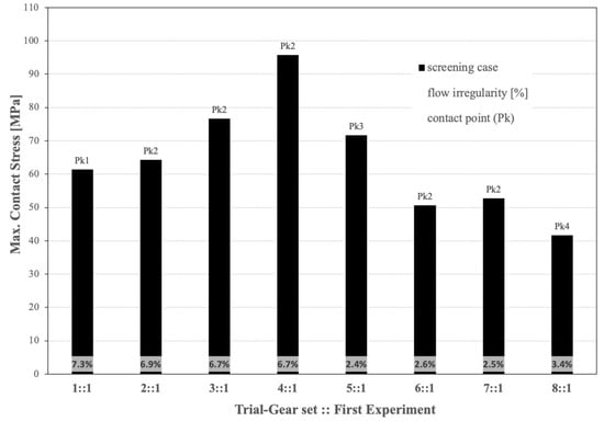
Figure 7.
Results of FEM maximum contact stress [MPa], GeroLAB flow irregularity [%], and contact point (Pk) of maximum contact stress in each gear set for the first Taguchi experiment (see Table 4).
Figure 8 illustrates the main effects plot for the screening case. The true critical characteristics (control factors) must be identified and minimized in number. This graphic aids in a better picture of the importance of the chosen control parameters. The larger the vertical increment between the two levels and the higher the slope in each factor, the more emphasis is placed on this parameter: the larger the HB S/N ratio, the better. The figure indicates that the parameters Z, RP, and rc are the strength factors. Conversely, the parameter wc, with a behavior almost horizontal between the two levels, is the first factor to be discarded, together with the parameter SK.
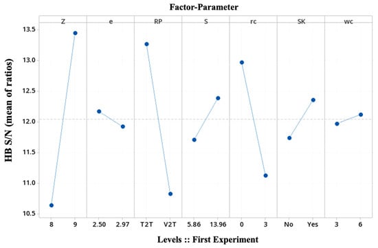
Figure 8.
Main effects plot for the first Taguchi experiment (see Table 4).
Obviously, the resolution is low in the first round of experiments (a small fractional factorial) and it will progress to higher-resolution experiments (a large fractional or full factorial) as few factors are going to be identified as influential.
In addition, this screening case has mixed geometrical basic parameters to define the trochoidal gear set, such as Z, e, S, and external gear rc, with working functions, such as SK and RP, where the former shows less dominance than the latter, and it will be discarded. Owing to the higher effect of the level ‘Yes’ in the shaft keyway, which is closer to real working function, all the gear sets in the incoming Taguchi experiments have a shaft keyway.
4.4. Second Taguchi Experiment: The Two-Levels-Four-Geometric-Basic-Parameters Case and One Noise Factor
The Taguchi approach to parameter design includes noise factors as related elements of the process that cannot be controlled or removed as a measure of the robust levels of the control factors. Thus, from the screening case, working function related to reference position is going to be used as a non-controlled process noise effect in this second Taguchi experiment.
L8(24) OA inner array with a resolution number of 2 (A and BxCxD, or AxB and CxD are in the same column), with one noise factor at the outer array L1 OA. Here, 16 FEM simulations were carried out in this second Taguchi (8 gear sets trials, 2 working functions noise factors). This second experiment encompasses less factor parameters (Z, e, S, and rc) corresponding to each column in Table 5. The outer array accommodates the noise factor at two levels, T2T and V2T, corresponding to columns N1 and N2 in Table 5.
Table 5.
The parameter design table of the second Taguchi experiment. (Please refer to Nomenclature section and Figure 2).
As in the case of FEM validation, the corresponding concordances reveal the important effect of the reference position in the numerical simulation. Comparing the gear set 8:1 in Figure 7 and the gear set 8:2 in Figure 9, both of them present the lower value of maximum contact stress with an acceptable value of 3.4% of flow irregularity. Since the 8:2 gear set uses the reference position as a noise factor to expose the robust levels of the control factors, these parameters will produce successively better approximations to converge to the sought gear, which is more suitable regarding contact stresses. Considering the location of contact points, it stays the same or within a unit difference.
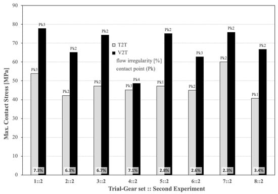
Figure 9.
Results of FEM maximum contact stress [MPa], GeroLAB flow irregularity [%], and contact point (Pk) of maximum contact stress in each gear set with the working function noise factor for the second Taguchi experiment (see Table 5).
Since the slope in the graphic is an indicator of the importance of a main effect, Figure 10 shows that the most dominant factor is the arc radius of the external gear tooth, S. In addition, this geometrical parameter S is considered with practical significance in the analysis of variance for HB S/N ratios (p = 0.083).
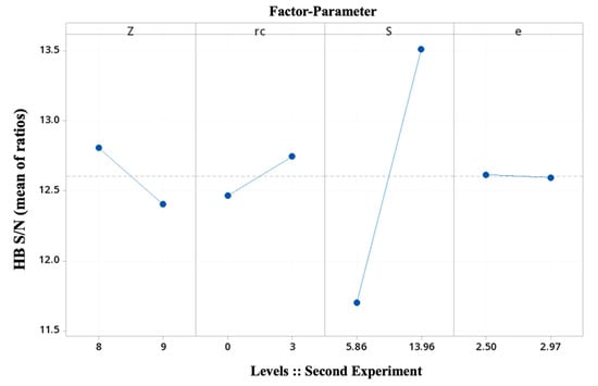
Figure 10.
Main effects plot for the second Taguchi experiment (see Table 5).
The mutual dependency between a pair of factors is an interaction of those factors. The interaction plot of the main effect factors Z and S is constructed by plotting the average response HB S/N values of each factor level combination and is presented in Figure 11. The effect of parameter S is estimated to be low since it would depend upon which level of parameter Z is being used. Being almost parallel lines is an indication of the absence of interaction between both factors. In addition, for this experiment, none of the studied interaction effects are statistically significant.

Figure 11.
Interaction plot between Z and S for the second Taguchi experiment (see Table 5).
On the other hand, these results are quite confusing, since it is difficult to accept Z as having a similar effect as rc in the gear set contact stresses as well as no significant interaction effect. One might add the well-known opposite effect on the volumetric characteristics of an even Z value, as it can be seen in the numerals of the flow irregularity in Figure 9. Upon debating this controversial effect, it is decided to go with a full factorial experiment by using the main geometric basic parameters: the number of external teeth, Z, the eccentricity, e, and the arc radius of the external gear tooth, S.
4.5. Third Taguchi Experiment: The Two-Levels-Three-Geometric-Basic-Parameters Case and Three Noise Factors
As previously mentioned, Taguchi parameter design is used to dampen the effect of noise, which includes parameters that are either uncountable or are too expensive to control, by choosing the proper level of control parameters. Then, once more, the question arises: why bother to assign these noise factors when they cannot be controlled or eliminated? The main reason, in this work, is related to the numerical simulations: several settings in the software environment could act as noise since they are associated with input operating conditions in the FEM simulation.
Then, the strategy is to force noise effects into the numerical simulation with an experimental layout based on an outer array only for operating conditions: a combination of outer noise (environmental-related, such as temperature, θ) and inner noise (function-related, such as torque, T, and friction coefficient, μ). If all of these noise factors were mixed together in an inner array for control factors, it would be a traditional cause of detection experiment: this is one of the major contributions of the Taguchi approach to noise emulation in FEM methodology.
Table 6 illustrates the L8(23) OA inner array with a resolution number of 4-high (full factorial, all items are in separate columns), with 3 noise factors. Here, 32 FEM simulations were carried out (8 gear sets trials, 4 FEM conditions noise factors). This third experiment encompasses three factor parameters (Z, e, and S) corresponding to each column. Owing to the low effect of rc, it was removed from the inner array, avoiding interactions confounded with the main effects and gaining resolution. The outer array accommodates the 3 noise factors at two levels, corresponding to columns N1, N2, N3, and N4 (refer to Table 6).
Table 6.
The parameter design table of the third Taguchi experiment. (Please refer to Nomenclature section and Figure 2).
Once this new OA with a high-resolution number has been selected, the factors can be assigned to the corresponding columns of the inner array and subsequent interaction columns located. In this new experiment, the interaction of Z and S is again studied since both have shown main effects in the HB S/N ratio of the previous first and second experiments.
In Figure 11 and Figure 12, results referring to the third experiment are reported. Figure 12 illustrates an important effect not influenced by the noise FEM conditions: the location of the maximum contact stress at the same contact point for all operating conditions once the three geometrical basic parameters are taken into account. It is also worth noting that the combination of a higher torque and a lower frictional factor results in higher contact stress, regardless of temperature.
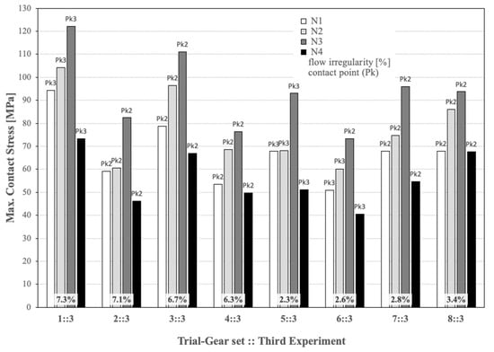
Figure 12.
Results of FEM maximum contact stress [MPa], GeroLAB flow irregularity [%], and contact point (Pk) of maximum contact stress in each gear set with 4 FEM conditions noise factors for the third Taguchi experiment (see Table 6).
Figure 13, as previously in Figure 10, shows that the most dominant factor is the arc radius of the external gear tooth, S, with practical significance in the analysis of variance for HB S/N ratios (p = 0.080). This is an expected result, since removing the parameter cutting radius shows its minimal effect. However, the absence of interactions confounded with the main effects in this full factorial experiment and the inclusion of the operating conditions reinforces this outcome. Now, the odd number of external gear teeth shows a dominant effect, and the eccentricity normalises its intrinsic interest and value.
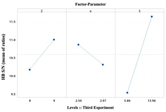
Figure 13.
Main effects plot for the third Taguchi experiment (see Table 6).
The interaction plot of the main effect factors Z and S is again computed and presented in Figure 14. The lines’ loss of parallelism and the effect of an odd number value for Z are indicated, although it is not statistically significant yet. The OA size and the interaction potential of interest to the experimenter are the key factors; as a general recommendation, it is preferred to study more factors than to study interactions [33].
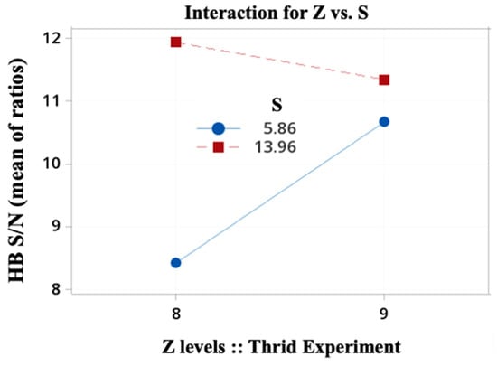
Figure 14.
Interaction plot between Z and S for the second Taguchi experiment (see Table 5).
4.6. Fourth Taguchi Experiment: The Mixed-Level-Design-Case with Three Noise Factors
The last experiment in this iterative process is designed to elucidate the ability of the Taguchi method to pinpoint the most suitable gear set configuration in front of FEM contact stress. With the learning from the previous three Taguchi experiments, it is decided to complete the study with an OA inner array with four control factors: the trochoidal gear set parameters (Z, e, and S) and the working function (RP). Note that it is decided to include the RP in the inner array, since its effects have been shown to be of noticeable importance. The FEM conditions are kept to the three operating conditions (T, μ, and θ) in the outer array to emulate noise effects. To complete the experiment, one more level is added to the trochoidal gear set parameters in a mixed-level design case. The Taguchi approach prefers using three or more levels of design parameters to estimate non-linear effects rather than two levels of classical DoE [30].
Table 7 illustrates the L18(21–33) mixed-level OA inner array with a resolution number of 1-low (no specific interaction columns available, except between AxB by using a specific layout). Here, 72 FEM simulations were carried out (18 gear sets trials, 4 FEM conditions noise factors). The outer array accommodates the three operating conditions (environmental-related, q, and function-related, T and μ) at two levels, corresponding to each column N1, N2, N3, and N4. In this mixed-level design, the parameters of the cutting radius and the wall width of the external gear are kept constant for the 18 gear sets, and factor interactions are not studied based on the results of the previous experiments.
Table 7.
The parameter design table of the fourth Taguchi experiment. (Please refer to Nomenclature section and Figure 2).
In Figure 15, the diversity of operating conditions is studied by crossing the inner array of control parameters by the outer array of noise factors. The slope of the HB S/N ratios once more illustrates the dominance of the three trochoidal gear set parameters (Z, e, and S) in front of the working function (RP). In addition, the main effects plots for means and standard deviations confirm the same tendency.
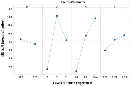
Figure 15.
Main effects plot for the fourth Taguchi experiment (see Table 7).
The statistical significance for Z and S supports this result. This fourth experiment shows statistical significance at an alpha level of 0.05 for Z and S, in particular, p = 0.053 and p = 0.050, respectively. Conversely, none of the interaction effects are significant.
For the contact stress experiment, the optimal control factor settings based on the highest HB S/N have been determined by the inspection of Figure 15. In order to decide which level is best to maximize the safety factor, the HB S/N ratios at each level (low, medium, and high) of each factor are compared. Hence, the levels are:
Z = 9 (level 2-medium); S = 10.4 mm (level 3-high); e = 2.93 mm (level 3-high) >>> Gear set 6::4.
Using the Taguchi approach for parametric design, the predicted optimum settings correspond to one of the rows of the matrix experiment: the gear set 6::4 in Table 7. In addition, its flow irregularity is 3%, a good value. (If the predicted optimum settings did not correspond to one of the rows, as a final step, a confirmation trial would be run). The reference position has a poor effect as a control factor. These settings maximize the safety factor for all noise configurations.
Finally, if the three trochoidal gear set parameters of the PZ9e285 gear set in Table 2 are compared with the results of the predicted optimum settings, it shows the reliability of the methodology since it points out the current geometry of a real-working gerotor pump.
5. Conclusions
In this paper, efforts to prove the reliability of the Taguchi techniques as an effective simulation-based strategy in the design of numerical simulations to assess contact stresses in trochoidal gears working in gerotor pumps were presented.
The validity of the Finite Element Model proposed in this paper was first decided to be proven by means of published results in the literature. The works of Ivanović and Biernacki, two researchers with long and solid careers in the mechanical analysis of gerotor pumps, were selected. Nomenclature and notation were integrated and unified for the research presented in this paper.
The average of the results of the nine simulations showed a discrepancy of 9% in the maximum contact stress at contact points, an acceptable error taking into account the available technical data and the limitation of simulating exactly the same geometries as the researchers. In addition, the location of the contact points was linked in all cases. The numerical model was verified to be valid within reasonable bounds and it was applied to the simulations designed by the Taguchi method.
The Taguchi approach was based on a sequential simulation-based design strategy of four experiments enabling a manageable number of gear sets. The resulting 128 numerical simulations accomplished the challenging goal of having the same volumetric capacity and dimensional constraints (gear thickness, external diameter of external gear, and the internal diameter of shaft hole located in the inner gear) to disengage contact stress performance from flow rate and casing. Furthermore, this innovative approach allowed bypassing the inherent multitude of geometric options in FEM numerical simulations and the ‘black box’ effect in the software input operating conditions, such as environmental-related temperature and function-related torque and friction coefficient. The progressive simulation-based planning narrowed down the number of parameters, reducing the solution space, under operating conditions that emulate noise effects.
Results of contact stress proved the arc radius of the external gear tooth to be the most dominant parameter. The odd number of external gear teeth was shown to be the second dominant effect, and the eccentricity demanded its intrinsic interest and value. The particular values of the statistical significance for both dominant parameters endorsed this conclusion. However, none of the interaction effects were statistically significant.
In particular, the feasibility of the proposed methodology to pinpoint the most suitable gear set configuration in front of FEM contact stress and to predict optimum settings in the geometry of real-working gerotor pumps in industrial designs was demonstrated. This statement was confirmed by the specific value combination of a trochoidal gear set: 9 external gear teeth, an arc radius of 10.4 mm, and an eccentricity of 2.93 mm. This optimized contact stress gear set yields to the targeted volumetric capacity of 1 cc·rev−1 per gear thickness and a proper flow irregularity of 3%.
Promising results are obtained in this approach for enhancing the quality of contact stress assessment without controlling or removing the cause of variation contributed to by the numerical simulation’s input settings. Taguchi robust design is an easier approach than classical optimization. Its accessibility as an open tool to end-users and its methodology are very much related to real production and products in industry, quality, and costs. This study has formulated its own approach in the field, assisting the numerical simulation procedure in the design process and leading to the gear set configuration of a real-working gerotor pump.
Regarding future work on the research presented in this paper, the next step will be to identify the control factors that move the mean to a pre-established contact stress target and predict the average response for each combination of control factor settings using the model for the response to the signal-to-noise ratio.
Author Contributions
Conceptualization, P.J.G.-M. and E.B.-M.; methodology, P.J.G.-M. and E.B.-M.; software, E.B.-M.; validation, P.J.G.-M. and E.B.-M.; writing—original draft preparation, P.J.G.-M.; writing—review and editing, P.J.G.-M. and E.B.-M.; supervision, P.J.G.-M. and E.B.-M.; project administration, P.J.G.-M. and E.B.-M. All authors have read and agreed to the published version of the manuscript.
Funding
This research received no external funding.
Data Availability Statement
Not applicable.
Acknowledgments
E.B.-M. is a Serra Húnter fellow. The authors would like to acknowledge the Generalitat de Catalunya for providing the necessary support to the research groups IAFARG (SGR 286, https://iafarg.upc.edu, accessed on 1 September 2022), CATMech (Tecnio, https://catmech.upc.edu/home, accessed on 1 September 2022), and Doctorats Industrials (2020 DI 45). The authors would like to thank Byon Zambrano Risco for participating in the research reported in this paper.
Conflicts of Interest
The authors declare no conflict of interest.
Nomenclature
| cv | Volumetric capacity/displacement |
| cv,H | Volumetric capacity/displacement per gear thickness |
| DeRi | External diameter of internal gear (DeRi = 2·ReRi) |
| ds | Shaft hole, internal diameter located in the inner gear |
| Dc | External diameter of external gear |
| e | Eccentricity (centre distance) |
| G | Radius of circle to complete external gear |
| H | Gear thickness |
| Ls | Shaft keyway length |
| O1 | Inner/internal gear centre |
| O2 | Outer/external gear centre |
| Pk | Contact point |
| rc | Cutting radius |
| r1 | Inner pitch circle |
| r2 | Outer pitch circle |
| R2 | Distance O2Ps |
| S | Arc radius of the external gear tooth |
| T | Torque |
| wc | Wall width of the external gear |
| Z, (Z − 1) | Number external (internal) teeth |
| λ | Tooth profile height correction coefficient (λ = r2/R2) |
| μ | Friction coefficient |
| θ | Temperature |
| υ | Equidistant index (υ = S·Z/R2) |
References
- Rundo, M. Models for flow rate simulation in gear pumps: A review. Energies 2017, 10, 1261. [Google Scholar] [CrossRef]
- Pareja-Corcho, J.; Moreno, A.; Simoes, B.; Pedrera-Busselo, A.; San-Jose, E.; Ruiz-Salguero, O.; Posada, J. A Virtual Prototype for Fast Design and Visualization of Gerotor Pumps. Appl. Sci. 2021, 11, 1190. [Google Scholar] [CrossRef]
- Kawamata, H.; Kuroda, S.; Tanaka, S.; Oshima, M. Improvement of Practical Electric Consumption by Drag Reducing under Cross Wind; SAE Technical Paper 2016-01-1626; SAE International: Warrendale, PA, USA, 2016; pp. 1–10. [Google Scholar] [CrossRef]
- Colbourne, J.R. Reduction of contact stress in internal gear pumps. J. Eng. Ind. 1976, 98, 1296–1300. [Google Scholar] [CrossRef]
- Roy, D. Mechanics and FEM estimation of deformation, gaps and stresses generated in star-ring active contacts of GEROTOR units during operation. J. Br. Soc. Mech. Sci. Eng. 2021, 43, 429. [Google Scholar] [CrossRef]
- Roy, D.; Maiti, R.; Das, P.K. Mechanics and FEM estimation of gaps generated in star-ring active contacts of ORBIT motor during operation. Int. J. Mech. Mater. Des. 2020, 16, 69–89. [Google Scholar] [CrossRef]
- Sliwinski, P. The methodology of design of satellite working mechanism of positive displacement machine. Sci. Rep. 2022, 12, 1–22. [Google Scholar] [CrossRef]
- Gamez-Montero, P.J.; Codina, E.; Castilla, R. A Review of Gerotor Technology in Hydraulic Machines. Energies 2019, 12, 2423. [Google Scholar] [CrossRef]
- Ivanović, L.; Devedžić, G.; Ćuković, S.; Mirić, N. Modeling of the Meshing of Trochoidal Profiles with Clearances. J. Mech. Des. 2012, 134, 041003. [Google Scholar] [CrossRef]
- Ivanović, L.; Josifović, D.; Ilić, A. Modelling of trochoidal gearing at the gerotor pump. Mech. Mach. Sci. 2013, 13, 553–562. [Google Scholar] [CrossRef]
- Ivanović, L.; Ilić, A.; Miloradović, D.; Josifović, D. Modelling and simulation of the load in the epicyclic rotary pump with trochoidal gear profiles. IOP Conf. Ser. Mater. Sci. Eng. 2018, 393, 1–9. [Google Scholar] [CrossRef]
- Ivanović, L.; Devedžić, G.; Mirić, N.; Ćuković, S. Analysis of forces and moments in gerotor pumps. Proc. Inst. Mech. Eng. C 2010, 224, 2257–2269. [Google Scholar] [CrossRef]
- Ivanović, L. Reduction of the maximum contact stresses by changing geometric parameters of the trochoidal gearing teeth profile. Meccanica 2016, 51, 2243–2257. [Google Scholar] [CrossRef]
- Ivanović, L.; Rakić, B.; Stojanović, B.; Matejić, M. Comparative analysis of analytical and numerical calculations of contact stresses at rotational elements of gerotor pumps. Appl. Eng. Lett. 2016, 1, 1–7. [Google Scholar]
- Ivanović, L.; Mackić, T.; Stojanović, B. Analysis of the instantaneous friction coefficient of the trochoidal gear pair. J. Balk. Tribol. Assoc. 2016, 22, 281–293. [Google Scholar]
- Ivanović, L.; Matejić, M. Improving gerotor pump performance through design, modelling and simulation. Int. J. Fluid Power 2021, 21, 327–346. [Google Scholar] [CrossRef]
- Biernacki, K.; Stryczek, J. Analysis of stress and deformation in plastic gears used in gerotor pumps. J. Strain Anal. Eng. Des. 2010, 45, 465–479. [Google Scholar] [CrossRef]
- Biernacki, K. Selection of the optimum tooth profile for plastic cycloidal gears. Proc. Inst. Mech. Eng. C 2014, 228, 3395–3404. [Google Scholar] [CrossRef]
- Stryczek, J.; Bednarczyk, S.; Biernacki, K. Strength analysis of the polyoxymethylene cycloidal gears of the gerotor pump. Arch. Civ. Mech. Eng. 2014, 14, 647–660. [Google Scholar] [CrossRef]
- Stryczek, J.; Bednarczyk, S.; Biernacki, K. Gerotor pump with POM gears: Design, production technology, research. Arch. Civ. Mech. Eng. 2014, 14, 391–397. [Google Scholar] [CrossRef]
- Biernacki, K. Analysis of the material and design modifications influence on strength of the cycloidal gear system. Int. J. Adv. Manuf. Technol. 2015, 16, 537–546. [Google Scholar] [CrossRef]
- Biernacki, K. New concept of power transmission for gerotor hydraulic machines. Proc. Inst. Mech. Eng. Part C J. Mech. Eng. Sci. 2021, 235, 4873–4883. [Google Scholar] [CrossRef]
- Biernacki, K. New construction of cycloidal gear unit made of plastics. Proc. Inst. Mech. Eng. Part C J. Mech. Eng. Sci. 2021, 235, 800–811. [Google Scholar] [CrossRef]
- Robison, A.; Vacca, A. Multi-objective optimization of circular-toothed gerotors for kinematics and wear by genetic algorithm. Mech. Mach. Theory 2018, 128, 150–168. [Google Scholar] [CrossRef]
- Robison, A.; Vacca, A. Performance comparison of epitrochoidal, hypotrochoidal, and cycloidal gerotor gear profiles. Mech. Mach. Theory 2021, 158, 104228. [Google Scholar] [CrossRef]
- De Martin, A.; Jacazio, G.; Sorli, M. Optimization of Gerotor Pumps with Asymmetric Profiles through an Evolutionary Strategy Algorithm. Machines 2019, 7, 17. [Google Scholar] [CrossRef]
- Tessari, F.; Galluzzi, R.; Amati, N. Efficiency-driven design methodology of gerotor hydraulic units. J. Mech. Des. 2020, 142, 063501. [Google Scholar] [CrossRef]
- Puliti, M.; Tessari, F.; Galluzzi, R.; Tonoli, A.; Amati, N. Design methodology of gerotor hydraulic machines for mechatronic applications. In Proceedings of the ASME International Mechanical Engineering Congress and Exposition, IMECE2021, Virtual, Online, 5 November 2021. [Google Scholar]
- Phadke, M.S. Quality Engineering Using Robust Design; Prentice Hall International: Englewood Cliffs, NJ, USA, 1989. [Google Scholar]
- Antony, J. Taguchi or classical design of experiments: A perspective from a practitioner. Sens. Rev. 2006, 26, 227–230. [Google Scholar] [CrossRef]
- Taguchi, G. Introduction to Quality Engineering: Designing Quality into Products and Processes; Asian Productivity Organization: Tokyo, Japan, 1986. [Google Scholar]
- Unal, R.; Dean, E.B. Taguchi approach to design optimization for quality and cost: An overview. In Proceedings of the 1991 Annual Conference of the International Society of Parametric Analysts, Hampton, VA, USA, 1 January 1991. [Google Scholar]
- Ross, R. Taguchi Techniques for Quality Engineering, 2nd ed.; McGraw-Hill: New York, NY, USA, 1996. [Google Scholar]
- Antony, J.; Jiju Antony, F. Teaching the Taguchi method to industrial engineers. Work Study 2001, 50, 141–149. [Google Scholar] [CrossRef]
- Jung, S.-Y.; Bae, J.-H.; Kim, M.-S.; Kim, C. Development of a new gerotor for oil pumps with multiple profiles. Int. J. Precis. Eng. Manuf. 2011, 12, 835–841. [Google Scholar] [CrossRef]
- Ivanović, L.T.; Veličković, S.N.; Stojanović, B.Ž.; Kandeva, M.; Jakimovska, K. The selection of optimal parameters of gerotor pump by application of factorial experimental design. FME Trans. 2017, 45, 159–164. [Google Scholar] [CrossRef]
- Ivanović, L.; Stojanović, B.; Blagojević, J.; Bogdanović, G.; Marinković, A. Analysis of the flow rate and the volumetric efficiency of the trochoidal pump by application of Taguchi method. Teh. Vjesn. 2017, 24, 265–270. [Google Scholar] [CrossRef]
- Lazić, L.; Milinković, S. Reducing software defects removal cost via design of experiments using Taguchi approach. Software Qual. J. 2015, 23, 267–295. [Google Scholar] [CrossRef]
- Vosniakos, G.C.; Kalattas, A.; Siasos, A. Optimal process planning for helical bevel gears using Taguchi design of simulated machining experiments. Proc. IMechE Part B J Eng. Manuf. 2018, 232, 2627–2640. [Google Scholar] [CrossRef]
- Choudhury, K.; Mandol, S.; Dan, P.K. Optimization of Operations in Epicyclic Gear Train Modelled Through Computer Aided Design. Asia-Pac. J. Manag. Res. Innov. 2014, 10, 323–335. [Google Scholar] [CrossRef]
- Stryczek, J.; Stryczek, P. Synthetic approach to the design, manufacturing and examination of gerotor and orbital hydraulic machines. Energies 2021, 14, 624. [Google Scholar] [CrossRef]
- Gamez-Montero, P.J.; Castilla, R.; Khamashta, M.; Codina, E. Contact problems of a trochoidal-gear pump. Int. J. Mech. Sci. 2006, 48, 14711480. [Google Scholar] [CrossRef]
- Gamez-Montero, P.J.; Castilla, R.; Mujal, R.; Khamashta, M.; Codina, E. GEROLAB package system: Innovative tool to design a trochoidal-gear pump. J. Mech. Des. 2009, 131, 074502. [Google Scholar] [CrossRef]
- GeroLAB Package System. Available online: http://www.gerolab.es (accessed on 1 February 2022).
- Ram Kumar, A.C.; Mohammed Raffic, N.; Ganesh Babu, K.; Selvakumar, S. Static structural analysis of spur gear using ANSYS 15.0 and material selection by COPRAS, MOORA techniques. Mater. Today Proc. 2021, 47, 25–36. [Google Scholar] [CrossRef]
- Karthick, L.; Shanmugasundaram, A.; Jagadish, C.A.; Prabhu, T.; Vidya Prakash, S. Numerical analysis of Modified tooth in Spur Gear for increasing the performance using fool proofing technology. Mater. Today Proc. 2021, 47, 5862–5868. [Google Scholar] [CrossRef]
- Benaïcha, Y.; Perret-Liaudet, J.; Beley, J.D.; Rigaud, E.; Thouverez, F. On a flexible multibody modelling approach using FE-based contact formulation for describing gear transmission error. Mech. Mach. Theory 2022, 167, 104505. [Google Scholar] [CrossRef]
- Rao, P.S. Contact Stress and Shear Stress Analysis of Spur Gear Using ANSYS and Theoretical. Int. J. Mod. Stud. Mech. Eng. 2016, 2, 9–14. [Google Scholar] [CrossRef]
- Lahtivirta, J.; Lehtovaara, A. Modelling of spur gear contact using a local adaptive finite element mesh. Tribologia 2016, 34, 41–55. [Google Scholar]
- Lisle, T.J.; Shaw, B.A.; Frazer, R.C. External spur gear root bending stress: A comparison of ISO 6336:2006, AGMA 2101-D04, ANSYS finite element analysis and strain gauge techniques. Mech. Mach. Theory 2017, 111, 1–9. [Google Scholar] [CrossRef]
- Puneeth, M.L.; Mallesh, G. Static contact behavior of asymmetric spur gear. Mater. Today Proc. 2021, 47, 3095–3104. [Google Scholar] [CrossRef]
- Munoz, G.A. Lecture 7: Mesh Quality & Advanced Topics; ANSYS Inc.: Canonsburg, PA, USA, 2015; p. 37. Available online: https://www.academia.edu/16970000/MESH_QUALITY_AND_ADVENCED_TOPICS_ANSYS_WORKBENCH_16_0 (accessed on 1 February 2022).
- Sliwinski, P. Determination of the Theoretical and Actual Working Volume of a Hydraulic Motor—Part II (The Method Based on the Characteristics of Effective Absorbency of the Motor). Energies 2021, 14, 1648. [Google Scholar] [CrossRef]
- Garcia-Vilchez, M.; Gamez-Montero, P.J.; Codina, E.; Castilla, R.; Raush, G.; Freire, J.; Rio, C. Computational fluid dynamics and particle image velocimetry assisted design tools for a new generation of trochoidal gear pumps. Adv. Mech. Eng. 2015, 7, 1–14. [Google Scholar] [CrossRef]
- Gamez-Montero, P.J.; Castilla, R.; Codina, E. Methodology based on best practice rules to design a new-born trochoidal gear pump. Proc. Inst. Mech. Eng. Part C J. Mech. Eng. Sci. 2018, 232, 1057–1068. [Google Scholar] [CrossRef]
- Skowrońska, J.; Kosucki, A.; Stawiński, Ł. Overview of Materials Used for the Basic Elements of Hydraulic Actuators and Sealing Systems and Their Surfaces Modification Methods. Materials 2021, 14, 1422. [Google Scholar] [CrossRef]
- Student, M.; Hvozdetskyi, V.; Stupnytskyi, T.; Student, O.; Maruschak, P.; Prentkovskis, O.; Skačkauskas, P. Mechanical Properties of Arc Coatings Sprayed with Cored Wires with Different Charge Compositions. Coatings 2022, 12, 925. [Google Scholar] [CrossRef]
Publisher’s Note: MDPI stays neutral with regard to jurisdictional claims in published maps and institutional affiliations. |
© 2022 by the authors. Licensee MDPI, Basel, Switzerland. This article is an open access article distributed under the terms and conditions of the Creative Commons Attribution (CC BY) license (https://creativecommons.org/licenses/by/4.0/).