Abstract
In the current scenario, where environmental concern determines the evolution of passenger cars, hybrid electric vehicles (HEV) represent a hub in the automotive sector to reach net-zero CO2 emissions. To fully exploit the energy conversion potential of advanced powertrains, proper energy management strategies are mandatory. In this work, a simulation study is presented, aiming at developing a new control strategy for a P3 parallel plug-in HEV (PHEV). The simulation model is built on MATLAB/Simulink. The proposed strategy is based on an alternative utilization of the thermal engine and electric motor to provide the vehicle power demand (efficient thermal/electric skipping strategy (ETESS)). An adaptive function is then introduced to develop a charge-blended control strategy. Fuel consumption along different driving cycles is evaluated by applying the novel adaptive-ETESS (A-ETESS). To have a proper comparison, the same adaptive function is built on the equivalent consumption minimization strategy (ECMS). Processor-in-the-loop (PIL) simulations are performed to benchmark the A-ETESS. Simulation results highlighted that the proposed strategy provides for a fuel economy similar to ECMS (worse of about 2.5% on average) and a computational effort reduced by 99% on average, opening the possibility of real-time on-vehicle applications.
1. Introduction
Hybrid electrified powertrains represent a key technology for the automotive industry’s transition toward decarbonization. The overall efficiency of this kind of powertrain is higher than that of traditional vehicles by integrating electrical motors and different energy storage systems (ESS) such as lithium-ion batteries or supercapacitors [1,2]. The coordination of the energy distribution among these powertrain components is a critical aspect of the control problem of HEVs because of their complex architectures. Proper energy management strategies (EMSs) are then mandatory to take advantage of these powertrains while respecting the safe working condition of each component [3].
A significant number of EMSs are proposed in the current literature. Zhang et al. [4] classify them in two main headlines: offline EMS and online EMS, represented as optimization-based EMSs; predictive EMSs; and learning-based EMSs. Offline EMSs can in turn be divided into global optimization-based EMSs and rule-based EMSs. Energy management by rule-based strategy mainly depends on local constraints and logical rules, usually determined based on the battery state of charge (SoC), driver power demand, or vehicle velocity. They are typically used in real-time applications thanks to their low computational effort [5,6]. Ding proposed a hybrid EMS using a rule-based control strategy and a genetic algorithm-based optimization to overcome the battery limitation [7]. Compared to the simple rule-based approach, the hybrid one achieved a fuel economy increase of 14% while preserving the simplicity of implementation.
Global optimization-based methods seek global optimal solutions since they need prior knowledge of the driving cycle. For this reason, they cannot directly be employed in real-time problems, and they are typically used as a benchmark tool for other EMSs [8]. Dynamic programming (DP) and Pontryagin minimum principle (PMP) are two of the most common offline EMSs. In DP, the optimal process is formulated to find the best cost function from an initial state to a final one [9,10]. It suffers from high complexity and high computational effort. For example, Polverino et al. [11] coupled DP and receding horizon approaches to overcome the DP issue of prior knowledge of the entire driving mission. Results showed a maximum drift from optimal consumption of less than 10% compared to the full horizon prediction. PMP is an analytical optimization method that transforms a global optimization problem into an instantaneous Hamiltonian optimization problem. It can achieve near-optimal results compared to DP, but it requires co-state estimation [12,13,14,15].
The equivalent consumption minimization strategy (ECMS) is the most known online EMS, and it can be considered a PMP simplification. It is based on the idea that the power is distributed by minimizing the instantaneous equivalent fuel consumption at each instant by converting the electricity consumption into the equivalent fuel consumption [16,17,18]. The weight of the electricity cost is represented by the equivalence factor (EF) that converts the electric power to an equivalent consumed fuel [19,20]. Wang et al. combined the ECMS with a fuzzy logic controller to adjust the equivalence factor based on the deviation between a reference SoC and the actual SoC of the battery [21]. Results showed that under a real driving cycle, the proposed strategy presented stronger robustness in the SoC sustainability compared to a rule-based EMS and an SoC-based adaptive-ECMS. Fuel consumption was improved up to 5.9%.
EMSs are strictly related to battery SoC management strategies. They are classified according to how the SoC varies with time. Charge-sustaining (CS) strategies are typical of hybrid electric vehicles, aiming to keep the SoC stable around a predefined target because of the lack of the possibility to recharge the battery from the grid. Plug-in hybrid electric vehicles can achieve a long driving distance than traditional fuel vehicles and non-tail gas emissions when they drive in pure electric mode. Different battery management strategies are needed to take advantage of these characteristics of PHEVs. Thanks to their simplicity, charge-depleting/charge-sustaining (CD-CS) strategies are widely implemented in heuristic hybrid control modules of PHEV [22,23]. They consist of a logic that first discharges the battery until a predefined value of battery SoC and then sustains it around this level. The charge-blended (CB) approach is similar to the CS one, but the desired SoC trajectory decreases almost linearly with the driven distance [24]. CB strategies well fit with PHEVs that can start the driving mission with a high SoC and aim to complete the mission with a lower one. In addition, in CB mode, the internal combustion engine (ICE) operates longer in its most efficient region, resulting in higher fuel economy [25]. In the current literature, various methods have been presented to realize adaptive CB control strategies [26,27]. Xie et al. [28] developed a data-driven ECMS for PHEVs. The EF was evaluated by an artificial neural network trained with a real-world speed profile. The results revealed that the proposed A-ECMS shows similar fuel consumption compared to DP and PMP and a reduced energy total cost compared to a simple CD-CS strategy for each tested case. However, computational time is more than 10 times increased compared to the rule-based strategy. In [29], a real-time blended energy management strategy for PHEVs is developed. It is based on the identification of real-time driving conditions by a K-means clustering algorithm. Simulation results showed that the fuel economy of the proposed strategy is improved up to 14.8% compared to a CD-CS strategy with a slightly higher computational time, highlighting the feasibility of real-time control.
In previous authors’ work [30,31], a simplified control strategy was proposed to reduce the computational effort typical of an ECMS-based strategy. Its basic idea is to alternatively utilize the thermal engine and the electric motor to satisfy the power demand (efficient thermal electric skipping strategy (ETESS)). The choice between the power units, at each time, depends on the comparison between the actual fuel consumption of the thermal engine that operates to fully satisfy the power request for driving and equivalent fuel consumption related to pure electric driving. In [32], the authors extended the ETESS logic to the management of a parallel PHEV by the introduction of an adaptive function (adaptive-ETESS (A-ETESS)). ETESS was demonstrated to perform similarly to ECMS both for CS and CB strategies but with a shorter than two orders of magnitude computational time.
In this work, the ETESS logic is further enhanced to improve the battery SoC management in a parallel P3 PHEV equipped with a small-size gasoline engine. Firstly, the vehicle architecture and the simulation model are presented. ETESS logic is then deeply discussed, with a focus on the adaptive function. To have a proper comparison term, the same adaptive function is implemented in the ECMS, realizing an adaptive-ECMS (A-ECMS). Results of A-ETESS and A-ECMS have then been discussed to benchmark the proposed control strategy in terms of fuel economy. In the end, A-ETESS and A-ECMS are executed on the same micro-controller unit (MCU), STMicroelectronics board NUCLEO-H743ZI2, realizing processor-in-the-loop (PIL) tests, to compare the computational effort of the two strategies, while the vehicle model is simulated on a PC host.
2. Vehicle Model and Simulation Platform
In this paper, a parallel P3 plug-in hybrid electric vehicle is adopted as the simulation model. Its powertrain is composed of a three-cylinder spark ignition engine (ICE), a manual clutch (CLT), an automatic transmission (MT), an electric reversible machine (EM), a DC-DC converter, a battery pack (BA), and an electric motor starter (STRT). The powertrain is schematized in Figure 1, in which the continuous black lines represent the mechanical connections, and the blue dotted lines represent the electrical ones. The vehicle’s main characteristics are listed in Table 1.
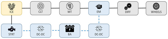
Figure 1.
Powertrain schematic of tested PHEV.

Table 1.
Main characteristics of the tested PHEV.
The vehicle architecture allows its operation in three modes, namely pure electric mode, pure thermal mode, and parallel mode, to satisfy the driver power demand. In pure thermal and pure electric modes, the entire commanded power is provided, respectively, by the thermal engine or by the electric machine; meanwhile, in parallel mode, it is provided in a combined manner by both the engine and the motor.
The simulation model under investigation is implemented in the MATLAB/Simulink environment as a backward dynamic model. The driver is modeled according to the typical approach that involves the use of a PID controller. The fuel consumption of the thermal engine and the motor/generator efficiency have been estimated by speed-load lookup tables, here depicted in Figure 2 and Figure 3, respectively. Concerning the battery module, it calculates the state of charge of the battery pack, according to SoC-dependent internal resistance and open-circuit voltage. The electrical starter is a series of excited DC motors. It draws energy from the battery to provide the engine with the necessary power during its starting phases. The starter motor torque is expressed by (Equation (1)):
in which iaf and Laf represent the field and armature current and the field and armature mutual inductance, respectively. The powertrain also includes a disk clutch to decouple the engine from the driveline. The clutch model involves friction and dynamic models that depend on the clutch lockup condition.
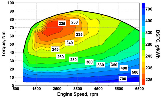
Figure 2.
Engine BSFC map, g/kWh.
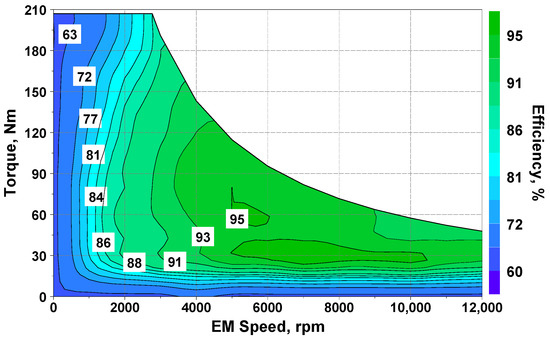
Figure 3.
Electric machine efficiency map, %.
Detailed control logic is therefore necessary for both the clutch and the motor starter, and it will be discussed in the following section.
3. Control Strategies
In this section, principles of ECMS and ETESS, suitable for HEV operating in charge-sustaining mode, are described. Then, the extension of these strategies for managing the PHEV in charge-blended mode is reported. Note that in both ETESS and ECMS implementation, an engine control module (ECM) and a transmission control module (TCM) are adopted.
The engine is schematized as a finite-state machine represented in Figure 4. When the ECM receives the engine activation command from the EMS, the motor starter delivers the power needed to accelerate the engine up to its idle speed. In the second stage, a PI controller adjusts the engine torque to match its speed with that of the driveline. Only at this time, the clutch pedal pressure is commanded to avoid mechanical losses during the coupling of the clutch disks. When the EMS does not require power to the thermal engine, the clutch disengagement is commanded by the ECM.
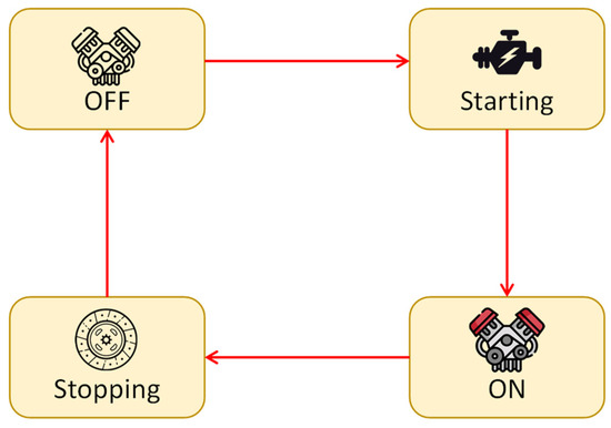
Figure 4.
Engine finite-state machine scheme.
To simplify the control logic and lower the computational effort, the desired gear is selected by the TCM from a vehicle speed-accelerator pedal position lookup table. During the gear shifting, the TCM operates a clutch disengagement.
3.1. Equivalent Consumption Minimization Strategy
The ECMS is a well-assessed strategy to reduce the global optimization problem of HEVs to an instantaneous minimization problem to be solved at each instant only using arguments based on actual energy flow in the powertrain. The related cost function can be expressed as follow:
It consists of an equivalent fuel rate obtained by summing the actual fuel rate (), and a contribution related to the electric power (LHV represents the fuel’s lower heating value and Pbatt the net electrical power as seen at the battery terminals) through an equivalence factor (s0). The equivalence factor represents the cost of the electric power drawn from the battery and its value for the optimal problem strongly depends on the driving conditions and vehicle characteristics. It is worth highlighting that the cost of electricity strongly depends on the operating conditions of the powertrain and, in particular, on the battery SoC, so, in charge-depleting mode, a proper adaptivity of the equivalence factor should be assigned.
3.2. Efficient Thermal Electric Skipping Strategy
The ETESS strategy has been already investigated in previous authors’ works [31,32], and it is here extended to improve the energy management on HEVs/PHEVs equipped with a small-size engine. Its main principle is based on an alternative utilization of the thermal engine and of the electric machine to satisfy the power demanded for traction. Based on this consideration, three operating modes can be defined: pure thermal mode, pure electric mode, and parallel mode. However, in this work, a fourth traction-charging mode is also considered. The choice among the pure thermal mode, pure electric mode, and the traction-charging mode depends, at each time, on the comparison between the total equivalent fuel consumption of each mode. It is defined as the sum of the actual fuel rate () and an equivalent fuel rate () related to the electric energy drawn from the battery, as reported in the following:
Parallel mode is considered in the comparison only if the thermal engine is not able to satisfy the entire power demand. The equivalent electric fuel rate concept is based on the idea that the power provided by the electric motor is produced by the thermal engine in an undefined time while working in its minimum brake-specific fuel consumption BSFCmin. Aiming at considering the power losses along the driveline, the power demand is hence adjusted through the efficiencies of all the driveline components. The ETESS logic is represented in the flowchart reported in Figure 5, and the detailed description of each mode and the analytical expressions for the evaluation of the total equivalent fuel consumption are given below.
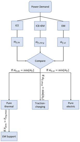
Figure 5.
Flowchart that schematizes the ETESS logic.
As schematized in Figure 6, in pure thermal mode the demanded power is entirely provided by the engine. The red arrows in Figure 6, Figure 7 and Figure 8 are representative of the energy fluxes between each drivetrain component.
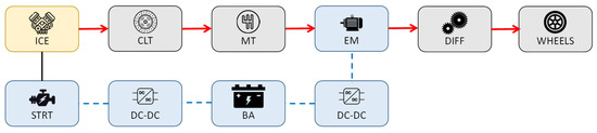
Figure 6.
Energy fluxes in pure thermal mode.
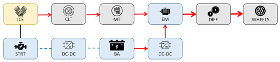
Figure 7.
Energy fluxes in pure thermal mode with EM support.
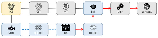
Figure 8.
Energy fluxes in pure electric mode.
The actual fuel rate of the thermal engine depends on its operating point, defined by torque output and rotational speed:
where Pdem is the commanded wheel power, and ηdiff and ηGB are, respectively, the efficiencies of the differential and gearbox. Since all the power is provided by the engine, the equivalent fuel rate of the electric powertrain section is null (Equation (5)).
In parallel mode, the thermal engine operates at its maximum load point and the electric motor delivers the lacking power to fulfill the demanded one (Figure 7).
The actual fuel rate and the equivalent one are defined as follows:
where ηEM, ηbatt, ηinv, are, respectively, the efficiencies of the electric motor, battery, and inverter. c0 is a tuning constant and represents the fuel-equivalent consumption of electric driving. Peng,max is the maximum engine power.
Opposite to the pure thermal mode, in pure electric mode, the demanded power is entirely provided by the motor (Figure 8).
In this mode, the actual fuel rate is null (Equation (8)) and the equivalent one is given by Equation (9):
The traction-charging mode is designed to enhance battery charging that would otherwise be allowed only by regenerative braking. This could lead to a lower level of SoC, especially during high-power demanding driving missions. Since the engine can provide a relatively low maximum power (Table 1), the vehicle would often work in parallel mode with the risk of causing the battery to be completely drained. In traction-charging mode, the thermal engine operates at its maximum load point and the electric machine works as a generator, utilizing the excess power provided by the engine to recharge the battery (Figure 9). The traction-charging mode is allowable only if the power demanded for traction is less than the maximum engine power (properly scaled by the drivetrain component efficiencies).
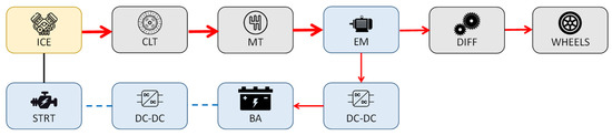
Figure 9.
Energy fluxes in traction-charging mode.
Expressions for the evaluation of the actual fuel rate and the equivalent fuel rate in traction-charging mode () are reported in the following:
Based on the above considerations, for pure thermal mode, parallel mode, and traction-charging mode, if the engine should be activated by the motor starter, the actual fuel rate is incremented by an equivalent activation fuel rate () defined as follows:
where Pstrt is the motor starter power, Peng is the engine power, and ηinv2 is the efficiency of the starter DC-DC converter.
It is relevant to highlight that, in the control logic, a simplified approach is utilized to describe the clutch efficiency. It is assumed that the clutch engagement and disengagement maneuvers are instantaneous and characterized by a unitary efficiency, although in the physical model of the drivetrain such processes are modeled in more detail. ETESS advantage consists of reduced computational effort.
3.3. Adaptive Strategies
In order to realize a CB strategy, an adaptive variant of ECMS and ETESS is proposed in this work. To this aim, a suitable target state of charge, labeled as SoC*, is assumed to linearly decreases with the driven distance [24].
where SoCini and SoCfin are, respectively, the SoC of the battery at the start and the end of the driving mission, x(t) is vehicle position at time instant t, and Lm is the total distance to be covered. Equation (14) highlights that the SoC target can be evaluated just through the a priori knowledge of the initial SoC (SoCini) before starting the driving, the desired SoC at the end of the mission (SoCfin), and the overall distance to be covered by the vehicle. This information could be provided by a map service provider in real applications on the vehicle.
The ETESS presented in Section 3.2 is extended to an adaptive CB strategy through the adaption of the tuning constant c0. This extension is based on the variability of battery properties with the SoC, as already explained in Section 3.1. For each of the operating modes, defined in Section 3.2, the equivalent fuel consumption (Equations (5)–(11)) and the total equivalent fuel consumption are reformulated as:
where the penalization factor kpen is included. During the driving mission two scenarios are possible:
- The actual SoC is higher than the reference SoC*. Pure electric driving must be promoted by lowering the cost related to it.
- The actual SoC is lower than the reference SoC*. Pure electric driving must be penalized by raising the cost associated with it.
The term kpen is differentiated for these two scenarios. For this reason, two different functions are built based on the difference between the actual SoC and the reference value and the normalized distance to travel (Δx = (Lm − x)/Lm). Then, logarithmic functions are selected to stabilize the control strategy, assuming that the correction of the adaptive cost raises with the traveled distance and with the SoC error. To achieve faster model running, the two functions are implemented in the form of a lookup table. Their values are depicted in Figure 10.
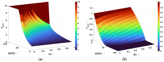
Figure 10.
Adaptive function kpen: (a) kpen for SoC(x) < SoC*(x).; (b) kpen for SoC(x) > SoC*(x).
Aiming at achieving consistent comparisons, an adaptive term is introduced in the ECMS, leading to the following expression:
The optimal values of parameters c0 and s0 are identified in preliminary tests on 4 driving cycles, namely WLTC, US06, Artemis Highway, and a Real Driving Cycle. To this aim, an automatic and iterative procedure implemented, which aims at minimizing the time-integral difference between actual SoC and its target SoC*. In each iteration, the values of c0 and s0 are kept constant, and they are automatically updated at the beginning of each driving cycle based on a gradient method. This procedure is repeated until the integrated SoC error attains the minimum level. In these analyses, according to typical plug-in hybrid operations, the parameters SoCiniand SoCfin are set equal to 80% and 30% to evaluate the SoC* function as expressed in (Equation (14)).
Exemplary results of this tuning procedure are depicted in Figure 11. This represents the SoC tendencies along the WLTC for the selected (1.18 in black), and discarded values of c0 (1.24 in red and 1.12 in blue). The figure highlights that the optimal value of c0 leads to a better agreement of the actual SoC with the target SoC* if compared to the other considered values of c0.
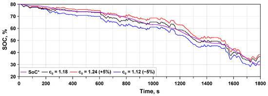
Figure 11.
Parametric analysis of c0 on SoC evolution along WLTC; comparison with SoC*.
The identified optimal values of c0 and s0 for the considered preliminary tests show a certain degree of correlation with the traveled distance, as reported in Figure 12. Two fitting functions (dashed lines in Figure 12), are identified to select an appropriate value of c0 or s0 whatever is the driving cycle, only by the knowledge of the overall distance to be covered. Those functions are used in the results presented in the following.
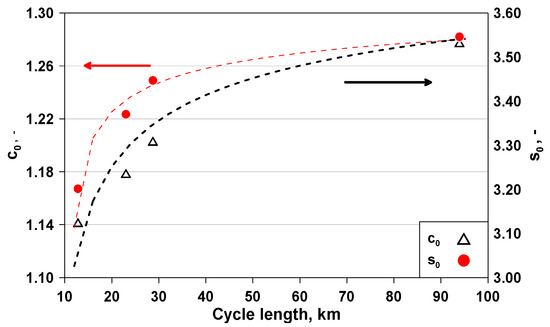
Figure 12.
Driving cycle-tuned values of c0 and s0 and their fitting functions.
4. Test Cases
A set of 8 driving cycles, listed in Table 2, are selected for the comparison of A-ETESS and A-ECMS, with the aim of exploring their behavior under various scenarios, highly different in terms of maximum and mean speeds and accelerations, and distance to be covered.
Table 2.
Tested driving cycle.
To strengthen the validity of the comparisons, two real driving emission (RDE)-compliant cycles, whose data have been collected from a GPS, are considered (Cycles 7 and 8 in Table 2, respectively).
5. Fuel Consumption Correction Related to Battery Discharge
In order to make a proper comparison between the two analyzed EMSs, “total consumed fuel” is selected as the assessment parameter to compare the energy consumption for the different test cases. In fact, two different energy sources are consumed during the driving mission, namely the fuel and the electrical energy stored in the battery. The overall battery discharge at the end of the driving cycle is then converted into an equivalent amount of fuel based on the hypothesis that the energy taken from the battery (ΔEbatt) has been produced by the engine operating at its average efficiency point () for the considered driving mission. The additional equivalent consumed fuel is expressed as:
The total fuel consumed () during the driving mission is then expressed as:
Equation (18) highlights that the engine should work with the highest possible average efficiency to minimize Δmeq.
6. Results
Numerical analyses are performed for all the test cases listed in Table 2. However, for sake of shortness the results for Test Cases 1, 2, and 8 (representative of a high-speed cycle, low-medium speed cycles, and RDE-compliant cycles) are discussed in detail in this section. According to preliminary analyses, the initial SoC is set equal to 80%, and the parameters SoCiniand SoCfinof target function SoC* are set equal to 80% and 30%, respectively.
Concerning Test Case 1, both A-ECMS and A-ETESS show to follow the SoC target profile and almost reach the desired SoC at the end of the mission (Figure 13b). The adaptive factor properly mirrors the error between the instantaneous SoC and the related target profile (Figure 13c).
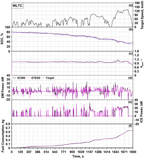
Figure 13.
WLTC, (a) target speed. ETESS/ECMS comparisons of battery SoC (b), kpen (c), EM power (d), ICE power (e), and cumulated consumed fuel (f).
By considering the portion of the cycle between 1400 and 1800 s, namely the high-speed one, both strategies activate the EM to support the ICE, which delivers its maximum torque to fulfill the power demanded at the wheels. This is also highlighted by the similar SoC trends for A-ETES and A-ECMS Figure 13b. A-ETESS sometimes commands battery recharges through ICE. In those phases, the ICE works at high load for a short time. Battery recharge phases of A-ECMS are longer and with a lower power delivered by the ICE thanks to the possibility to modulate the power split. Globally, the strategies behave in a very similar way, which is evidenced also by analogous levels of accumulated consumed fuel (Figure 13f).
Detailed outcomes for the FTP75 cycle (Test Case 2 of Table 2) are depicted in Figure 14. The adaptive term is often next to the unit (Figure 14c), and the trends of the SoC are quite close to the target (Figure 14b). If A-ETESS and A-ECMS similarly manage the EM, some differences arise in the ICE utilization, as highlighted in Figure 14d,e, respectively. The final consumed fuels are similar, but the A-ETESS involves a greater battery discharge at the cycle end than A-ECMS, leading to a slightly worse fuel economy. The same differences in the battery recharge management between A-ECMS and A-ETESS discussed for WLTC are confirmed in the FTP75 cycle.
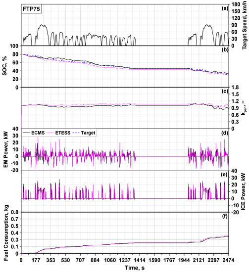
Figure 14.
FTP75, (a) target speed. ETESS/ECMS comparisons of battery SoC (b), kpen (c), EM power (d), ICE power (e), and cumulated consumed fuel (f).
In Figure 15, the instantaneous trends of SoC (Figure 15b) and the adaptive term (Figure 15c) along the RDE2-compliant cycle are represented (Test Case 8 of Figure 15). Furthermore, the assessments of ICE and EM powers and consumed fuel are depicted in Figure 15d–f, respectively. By comparing the SoC and EM power trends for the two strategies, subtle differences arise in electrical energy usage because of the possibility of A-ECMS exploring an intermediate power split. During the majority of the cycle, the strategies chose to drive the vehicle in the same mode. In the last portion of the cycle, between about 4400 and 5400 s, both strategies command the ICE to operate at its maximum torque working point, also actuating a certain battery recharge. These similar management lead to similar final values for the cumulated fuel consumed.
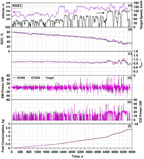
Figure 15.
RDE2, (a) target speed. ETESS/ECMS comparisons of battery SoC (b), kpen (c), EM power (d), ICE power (e), and cumulated consumed fuel (f).
In the bar chart of Figure 16, the total fuel consumed per kilometer of the two strategies is reported to make a global synthetic comparison. Over each couple of bars is shown the percentage difference, evaluated as:
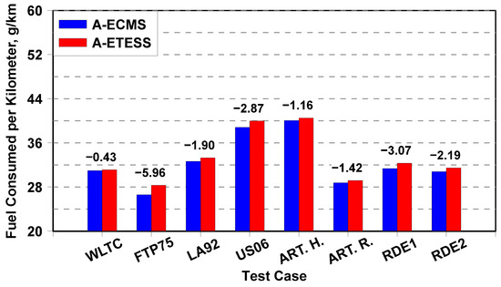
Figure 16.
Comparison between A-ECMS and A-ETESS of kilometric consumed fuel and percent difference for the test cases of Table 2.
As can be observed, the average total fuel consumed difference between A-ETESS and A-ECMS is below 2.4%. Greater differences emerge only for Test Case 2, for the issues related to the management of battery recharge. Concerning vehicle drivability, there are no relevant differences between the two strategies, as highlighted by the maximum and averaged values of vehicle acceleration derivatives reported in Table 3.
Table 3.
Number of engine ON per minute and maximum and mean of vehicle acceleration derivative for the test cases of Table 2.
Comparing the number of engine ON per minute, reported in Table 3, the differences between the A-ETESS and A-ECMS are not significant. A-ETESS, due to its intrinsic concept, more frequently needs engine switch-on, but the occurrences of such events are in most cases slightly higher than A-ECMS ones. A-ETESS performs even better than A-ECMS for Case 5. Further efforts may be devoted to reducing the number of engine switch-on in a real on-vehicle application, with the aim to optimize the thermal management and effectiveness of after-treatment devices of the ICE.
7. PIL Test
Further analyses are performed to estimate the computational effort and execution time of A-ETESS and A-ECMS on a real board. To this aim, processor-in-the-loop tests are executed. Hence, a C-Code has been generated through the adoption of a Simulink Coder R2022a (MathWorks, Inc., Natick, MA, USA), then loaded on a high-performance board for optimized control, the so-called NUCLEO-H743 (STMicroelectronics, Plan-les-Ouates, Geneva, Switzerland) [33]. The latter is equipped with an ARM® Cortex®-M7 (STMicroelectronics, Plan-les-Ouates, Geneva, Switzerland) running up to 480 MHz, 424 Core-Mark/1027 DMIPS (STMicroelectronics, Plan-les-Ouates, Geneva, Switzerland) executing from flash memory. The GNU Tools for ARM Embedded Processors are set for the building process.
While the powertrain control strategy runs on the NUCLEO board, the vehicle and powertrain physical models are executed on a PC host. Hence, the here-adopted PIL testing procedure is based on their asynchronous serial communication. Once the simulation in PIL mode ends, Simulink generates the code execution profiling report. The outcomes are similar for all the test cases in Table 2, so, for sake of brevity, in Table 4, the only results reported are related to WLTC. The latter shows that A-ETESS is two orders of magnitude faster than A-ECMS, with a maximum CPU utilization of 0.022% in the place of 18.18%.
Table 4.
PIL testing results for WLTC.
For both strategies, the average execution time turns out to be lower than the typical cycle time of a can message for an updated engine torque request (10 ms), but the A-ETESS demonstrated a reduced computational effort confirming the possibility to run multiple control strategies on the same microcontroller, optimizing its utilization.
8. Conclusions
This paper describes the enhancement of a simplified control strategy, named A-ETESS, for plug-in hybrid electric vehicles equipped with a downsized ICE. The simulation study is based on a vehicle model built in the MATLAB/Simulink environment. The proposed A-ETESS is a charge-blended battery control strategy that provides for a linearly decreasing target SoC with the driven distance. The fundamental idea of the ETESS to alternatively utilize the thermal engine and the electric motor to provide the power requested to drive the vehicle is here improved by considering an additional charging-traction mode to enhance battery recharging and SoC management. The ETESS is here extended to an adaptive EMS through the implementation of an adaptive logarithmic-based function properly selected to make the strategy stable and implemented in the form of a two-dimensional lookup table. The same adaptive function is introduced in the ECMS to have a proper comparison with the proposed strategy in terms of fuel consumption and computational effort.
In the first stage, the two strategies are properly tuned to minimize the average difference between actual SoC and target SoC for five driving cycles, namely US06, WLTC, Artemis Highway, and an RDE cycle, through the selection of cycle-dependent tuning parameters. Those are then correlated to the traveled distance by a fitting function to generalize the approach whatever is the driving cycle to be covered. Simulation results highlighted that the average total fuel consumption difference between A-ETESS and A-ECMS is below 2.5%.
PIL tests are realized to compare the computational time of A-ETESS and A-ECMS and to verify the possibility to implement the A-ETESS in a real-time vehicle application. The EMSs are executed on the NUCLEO-H743, while the vehicle model is simulated on a PC host. PIL results highlighted that A-ETESS can run two orders of magnitude faster than A-ECMS. Since the A-ETESS execution time is lower than the typical cycle time of a CAN message, real-time control of the engine and motor torque requests appear feasible on-vehicle.
Future developments will provide the improvement of the A-ETESS, taking advantage of additional information available in connected vehicles. Further, neural networks, properly trained with data provided by vehicle connectivity or by optimal strategies such as DP or PMP, will be also considered to cooperate with the proposed strategy to improve its performance in terms of adaptivity and fuel economy.
Author Contributions
Conceptualization, V.D.B., E.M.; methodology, V.D.B., E.M.; software, M.P.; validation, V.D.B., M.P., E.M.; formal analysis, M.P., E.M.; investigation, M.P.; resources, V.D.B.; data curation, M.P.; writing—original draft preparation, M.P., E.M., V.D.B.; writing—review and editing, M.P., E.M., V.D.B.; visualization, M.P., E.M.; supervision, V.D.B.; All authors have read and agreed to the published version of the manuscript.
Funding
This research received no external funding.
Data Availability Statement
Not applicable.
Conflicts of Interest
The authors declare no conflict of interest.
Abbreviations
| Notations | |
| m | Mass |
| Battery energy variation | |
| Fuel mass rate | |
| Equivalence factor | |
| Adaptive term | |
| Battery power | |
| T | Torque |
| J | Cost function |
| LHV | Lower heating value |
| Weight of electricity cost | |
| iaf | FIELD and armature current |
| Laf | FIELD and armature mutual inductance |
| Acronyms | |
| A-ECMS | Adaptive-ECMS |
| A-ETESS | Adaptive-ETESS |
| BA | Battery pack |
| BSFC | Brake-specific fuel consumption |
| CB | Charge blended |
| CD | Charge depleting |
| CS | Charge sustaining |
| DP | Dynamic programming |
| ECMS | Equivalent consumption minimization strategy |
| EF | Equivalence factor |
| EM | Electric motor |
| EM | Electric machine |
| EMS | Energy management strategy |
| ESS | Energy storage system |
| ETESS | Efficient thermal/electric skipping strategy |
| FC | Fuel consumption |
| HEV | Hybrid electric vehicle |
| HIL | Hardware in the loop |
| ICE | Internal combustion engine |
| LHV | Lower heating value |
| MCU | Microcontroller unit |
| MT | Manual transmission |
| PHEV | Plug-in HEV |
| PIL | Processor in the loop |
| PMP | Pontryagin minimum principle |
| RDE | Real driving emission |
| SoC | State of charge |
| STRT | Starter |
| Subscript | |
| batt | Battery |
| dem | Demanded |
| diff | Differential |
| eq | Equivalent |
| f | Fuel |
| fin | Final |
| GB | Gearbox |
| ini | Initial |
| inv | Inverter |
| m | Mission |
| el | Electric |
| th | Thermal |
| STRT | Starter |
| eng | Engine |
| max | Maximum |
| EM | Electric machine |
| min | Minimum |
| tot | Total |
| Superscript | |
| . | Time derivative |
| * | Target |
| Greeks | |
| η | Efficiency |
References
- Zhuang, W.; Li, S.; Zhang, X.; Kum, D.; Song, Z.; Yin, G.; Ju, F. A Survey of Powertrain Configuration Studies on Hybrid Electric Vehicles. Appl. Energy 2020, 262, 114553. [Google Scholar] [CrossRef]
- Singh, K.V.; Bansal, H.O.; Singh, D. A Comprehensive Review on Hybrid Electric Vehicles: Architectures and Components. J. Mod. Transp. 2019, 27, 77–107. [Google Scholar] [CrossRef]
- Lü, X.; Wu, Y.; Lian, J.; Zhang, Y.; Chen, C.; Wang, P.; Meng, L. Energy Management of Hybrid Electric Vehicles: A Review of Energy Optimization of Fuel Cell Hybrid Power System Based on Genetic Algorithm. Energy Convers. Manag. 2020, 205, 112474. [Google Scholar] [CrossRef]
- Zhang, F.; Wang, L.; Coskun, S.; Pang, H.; Cui, Y.; Xi, J. Energy Management Strategies for Hybrid Electric Vehicles: Review, Classification, Comparison, and Outlook. Energies 2020, 13, 3352. [Google Scholar] [CrossRef]
- Pam, A.; Bouscayrol, A.; Fiani, P.; Noth, F. Rule-Based Energy Management Strategy for a Parallel Hybrid Electric Vehicle Deduced from Dynamic Programming. In Proceedings of the 2017 IEEE Vehicle Power and Propulsion Conference (VPPC), Belfort, France, 11–14 December 2017. [Google Scholar] [CrossRef]
- Zhu, D.; Pritchard, E.; Dadam, S.R.; Kumar, V.; Xu, Y. Optimization of Rule-Based Energy Management Strategies for Hybrid Vehicles Using Dynamic Programming. Combust. Eng. 2021, 184, 3–10. [Google Scholar] [CrossRef]
- Ding, N.; Prasad, K.; Lie, T.T. Design of a Hybrid Energy Management System Using Designed Rule-Based Control Strategy and Genetic Algorithm for the Series-Parallel Plug-in Hybrid Electric Vehicle. Int. J. Energy Res. 2021, 45, 1627–1644. [Google Scholar] [CrossRef]
- Peng, J.; He, H.; Xiong, R. Rule Based Energy Management Strategy for a Series–Parallel Plug-in Hybrid Electric Bus Optimized by Dynamic Programming. Appl. Energy 2017, 185, 1633–1643. [Google Scholar] [CrossRef]
- Wang, Y.; Jiao, X. Dual Heuristic Dynamic Programming Based Energy Management Control for Hybrid Electric Vehicles. Energies 2022, 15, 3235. [Google Scholar] [CrossRef]
- Van Harselaar, W.; Schreuders, N.; Hofman, T.; Rinderknecht, S. Improved Implementation of Dynamic Programming on the Example of Hybrid Electric Vehicle Control. IFAC-Pap. 2019, 52, 147–152. [Google Scholar] [CrossRef]
- Polverino, P.; Arsie, I.; Pianese, C. Optimal Energy Management for Hybrid Electric Vehicles Based on Dynamic Programming and Receding Horizon. Energies 2021, 14, 3502. [Google Scholar] [CrossRef]
- Kim, N.W.; Lee, D.H.; Zheng, C.; Shin, C.; Seo, H.; Cha, S.W. Realization of Pmp-Based Control for Hybrid Electric Vehicles in a Backward-Looking Simulation. Int. J. Automot. Technol. 2014, 15, 625–635. [Google Scholar] [CrossRef]
- Zhang, J.; Zheng, C.; Cha, S.W.; Duan, S. Co-State Variable Determination in Pontryagin’s Minimum Principle for Energy Management of Hybrid Vehicles. Int. J. Precis. Eng. Manuf. 2016, 17, 1215–1222. [Google Scholar] [CrossRef]
- Kang, C.; Song, C.; Cha, S. A Costate Estimation for Pontryagin’s Minimum Principle by Machine Learning. In Proceedings of the 2018 IEEE Vehicle Power and Propulsion Conference (VPPC), Chicago, IL, USA, 27–30 August 2018. [Google Scholar] [CrossRef]
- Ghasemi, M.; Song, X. A Computationally Efficient Optimal Power Management for Power Split Hybrid Vehicle Based on Pontryagin’s Minimum Principle. In Proceedings of the ASME 2017 Dynamic Systems and Control Conference (DSCC), Tysons, VA, USA, 11–13 October 2017; Volume 2. [Google Scholar] [CrossRef]
- Li, H.; Ravey, A.; N’Diaye, A.; Djerdir, A. Online Adaptive Equivalent Consumption Minimization Strategy for Fuel Cell Hybrid Electric Vehicle Considering Power Sources Degradation. Energy Convers. Manag. 2019, 192, 133–149. [Google Scholar] [CrossRef]
- Gao, A.; Deng, X.; Zhang, M.; Fu, Z. Design and Validation of Real-Time Optimal Control with ECMS to Minimize Energy Consumption for Parallel Hybrid Electric Vehicles. Math. Probl. Eng. 2017, 2017, 3095347. [Google Scholar] [CrossRef]
- Zhou, B.; Burl, J.B.; Rezaei, A. Equivalent Consumption Minimization Strategy with Consideration of Battery Aging for Parallel Hybrid Electric Vehicles. IEEE Access 2020, 8, 204770–204781. [Google Scholar] [CrossRef]
- Rezaei, A.; Burl, J.B.; Zhou, B. Estimation of the ECMS Equivalent Factor Bounds for Hybrid Electric Vehicles. IEEE Trans. Control Syst. Technol. 2018, 26, 2198–2205. [Google Scholar] [CrossRef]
- Hegde, S.; Bonfitto, A.; Rahmeh, H.; Amati, N.; Tonoli, A. Optimal Selection of Equivalence Factors for ECMS in Mild Hybrid Electric Vehicles. In Proceedings of the ASME Design Engineering Technical Conference, Virtual, 17–19 August 2021; Volume 1. [Google Scholar] [CrossRef]
- Wang, S.; Huang, X.; Lopez, J.M.; Xu, X.; Dong, P. Fuzzy Adaptive-Equivalent Consumption Minimization Strategy for a Parallel Hybrid Electric Vehicle. IEEE Access 2019, 7, 133290–133303. [Google Scholar] [CrossRef]
- Gissing, J.; Themann, P.; Baltzer, S.; Lichius, T.; Eckstein, L. Optimal Control of Series Plug-In Hybrid Electric Vehicles Considering the Cabin Heat Demand. IEEE Trans. Control Syst. Technol. 2016, 24, 1126–1133. [Google Scholar] [CrossRef]
- Huang, Y.; Wang, H.; Khajepour, A.; He, H.; Ji, J. Model Predictive Control Power Management Strategies for HEVs: A Review. J. Power Sources 2017, 341, 91–106. [Google Scholar] [CrossRef]
- Tribioli, L.; Barbieri, M.; Capata, R.; Sciubba, E.; Jannelli, E.; Bella, G. A Real Time Energy Management Strategy for Plug-in Hybrid Electric Vehicles Based on Optimal Control Theory. Energy Procedia 2014, 45, 949–958. [Google Scholar] [CrossRef]
- Shankar, R.; Marco, J.; Assadian, F. Design of an Optimized Charge-Blended Energy Management Strategy for a Plugin Hybrid Vehicle. In Proceedings of the 2012 UKACC International Conference on Control, Cardiff, UK, 3–5 September 2012; pp. 619–624. [Google Scholar] [CrossRef]
- Denis, N.; Dubois, M.R.; Dubé, R.; Desrochers, A. Blended Power Management Strategy Using Pattern Recognition for a Plug-in Hybrid Electric Vehicle. Int. J. Intell. Transp. Syst. Res. 2016, 14, 101–114. [Google Scholar] [CrossRef]
- Capancioni, A.; Brunelli, L.; Cavina, N.; Perazzo, A. Development of Adaptive-ECMS and Predictive Functions for Plug-in HEVs to Handle Zero-Emission Zones Using Navigation Data. In SAE Technical Papers; SAE International: Warrendale, PA, USA, 2021. [Google Scholar] [CrossRef]
- Xie, S.; Hu, X.; Qi, S.; Lang, K. An Artificial Neural Network-Enhanced Energy Management Strategy for Plug-in Hybrid Electric Vehicles. Energy 2018, 163, 837–848. [Google Scholar] [CrossRef]
- Lei, Z.; Qin, D.; Zhao, P.; Li, J.; Liu, Y.; Chen, Z. A Real-Time Blended Energy Management Strategy of Plug-in Hybrid Electric Vehicles Considering Driving Conditions. J. Clean. Prod. 2020, 252, 119735. [Google Scholar] [CrossRef]
- de Bellis, V.; Malfi, E.; Tufano, D.; Bozza, F. Efficient Thermal Electric Skipping Strategy Applied to the Control of Series/Parallel Hybrid Powertrain. In SAE Technical Papers; SAE International: Warrendale, PA, USA, 2020. [Google Scholar] [CrossRef]
- de Bellis, V.; Malfi, E.; Zaccardi, J.M. Development of an Efficient Thermal Electric Skipping Strategy for the Management of a Series/Parallel Hybrid Powertrain. Energies 2021, 14, 889. [Google Scholar] [CrossRef]
- De Bellis, V.; Piras, M.; Malfi, E. Development of an Adaptive Efficient Thermal/Electric Skipping Control Strategy Applied to a Parallel Plug-in Hybrid Electric Vehicle. In SAE Technical Paper; SAE International: Warrendale, PA, USA, 2022. [Google Scholar] [CrossRef]
- ST Microelectronics STM32H7 Nucleo-144 Boards (MB1364) 2020. Available online: https://www.st.com/resource/en/data_brief/nucleo-h743zi.pdf (accessed on 26 September 2022).
Publisher’s Note: MDPI stays neutral with regard to jurisdictional claims in published maps and institutional affiliations. |
© 2022 by the authors. Licensee MDPI, Basel, Switzerland. This article is an open access article distributed under the terms and conditions of the Creative Commons Attribution (CC BY) license (https://creativecommons.org/licenses/by/4.0/).