1. Introduction
The energy model that has been introduced and developed in the last century to enable economic development is no longer sustainable under these new climate and environmental conditions. For instance, in the current Electrical Power System (EPS) model, thermoelectric generation is strongly predominant; this current source of energy today is the main cause of greenhouse gas emissions, including CO2. The increase in these emissions has highlighted the need for evident and rapid decarbonization and efficiency of all energy sectors to limit their impacts on the environment and achieve a more sustainable system.
To this end, several national and international agreements have been reached, such as the PNIEC (Integrated National Plan for Energy and Climate 2030), the Clean Energy Package, and the European Green Deal, which set various strategic goals to counteract the increase in global average temperature. One of the most challenging goals is the strong increase in energy generation from renewable energy sources, i.e., wind and photovoltaic.
The generation of Renewable Energy Sources (RESs), has been identified as one of the main enablers of the transition. Thanks to their operation principles, these types of energy generation allow the production of energy without CO2 emissions, and they help reduce energy prices, which (ultimately) benefits the consumers.
The power plants based on RES, specifically wind and solar generators, are characterized by nonprogrammable production profiles, which means that the electricity produced by such plants does not follow the dynamics of energy demand for consumption, but the dynamic characteristics of each energy source. Moreover, this type of technology is mainly based on inverter technology, i.e., systems connected to the grid through static components, which have a lower tendency to comply with the variation of power system the basic parameters for the safe operation of the grid than the traditional groups, that interface through the use of rotating machines [
1,
2].
These properties have the following implications for the management of the system [
3,
4]:
Reduction in the number of generation resources capable of providing frequency regulation (active power regulation) and voltage regulation (reactive power regulation) services;
Reduction in electromechanical inertia, which worsens the dynamic response after disturbances;
Reduction in short-circuit power, which worsens the quality of service and the risk of propagation of voltage disturbances;
Reduction in the margin to cover peak loads, which can be demonstrated in hours to a low production of RES;
Increasing periods of overgeneration (production greater than demand) and line congestions, which without sufficient storage capacity or reserve can cause cuts in the energy produced;
Increase in steepness of the evening ramp of the residual load, due to the sudden drop in the production of solar plants in the darkest hours, so that a fast response from flexible systems is essential;
Increase in reserve requirements due to the increasing presence of nonprogrammable renewable energy sources (NP-RES)-based power plants and their randomness.
Looking at these impacts, the increase in the share of RES generation brings the electricity system to conditions of lower reliability, safety, and stability. In this context, stability, particularly transient stability, plays an important role as an index of robustness of the system, subject by its nature to events such as faults and disturbances [
5].
Transient stability represents the ability of the system to withstand transient events caused by a disturbance, generally important, e.g., a short-circuit, and to reach the nominal operating conditions. For this reason, it has been the subject of many studies and is already described in the literature [
6,
7]. A part of this also applies to the impact on transient stability caused by wind turbine integration in the current traditional electric power systems [
8,
9].
This article first examines the impact of RES generation (in this case, wind energy) on the transient stability of the system when wind energy is added to existing traditional generation and when it replaces some of that generation. The main objective of this work is to analyze and compare some of the solutions to improve the transient stability, such as SVC (static VAR compensator), STATCOM (static synchronous compensator), fast excitation system, and the doubling of a transmission line, as performed in [
6]. In this way, it is possible to evaluate and compare the effects of these solutions in a system with RES generation in two different scenarios and then compare them with those of a traditional system.
The PowerWorld Simulator is used for this paper. The IEEE 9-bus system used as a case study in [
6] is modified by adding wind turbines. The decision to start with the IEEE 9-bus system is due to the widespread use of this grid, which allows for comparison, and its simplicity, which allows for various sensitivity analyses thanks to the small number of buses; this type of analysis would indeed be complicated and time-consuming for larger grids. As in [
6], the system is modeled using component that are already tested and present in the IEEE or WECC lists and that are present in most power system simulator libraries. This is implemented to reach general and reproducible results. However, specific studies about new wind turbine controllers are present in the literature (e.g., [
10,
11]), which investigate new solutions to face adequately the stability issues in power system with low inertia.
The contributions of this paper are as follows:
Sensitivity analysis to identify the generation bus in which to insert the wind generator, so as to define the worst operating condition in terms of transient stability following the insertion of the wind plant;
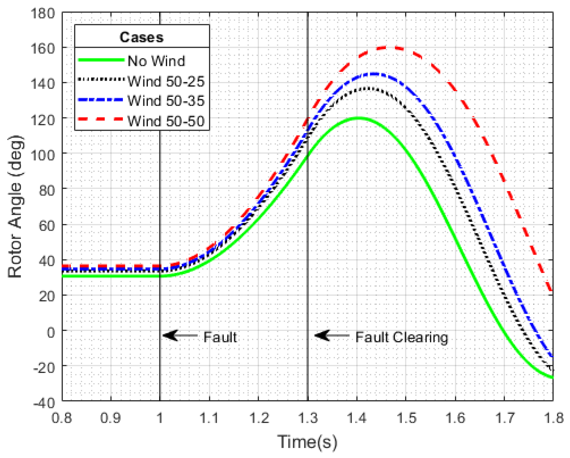
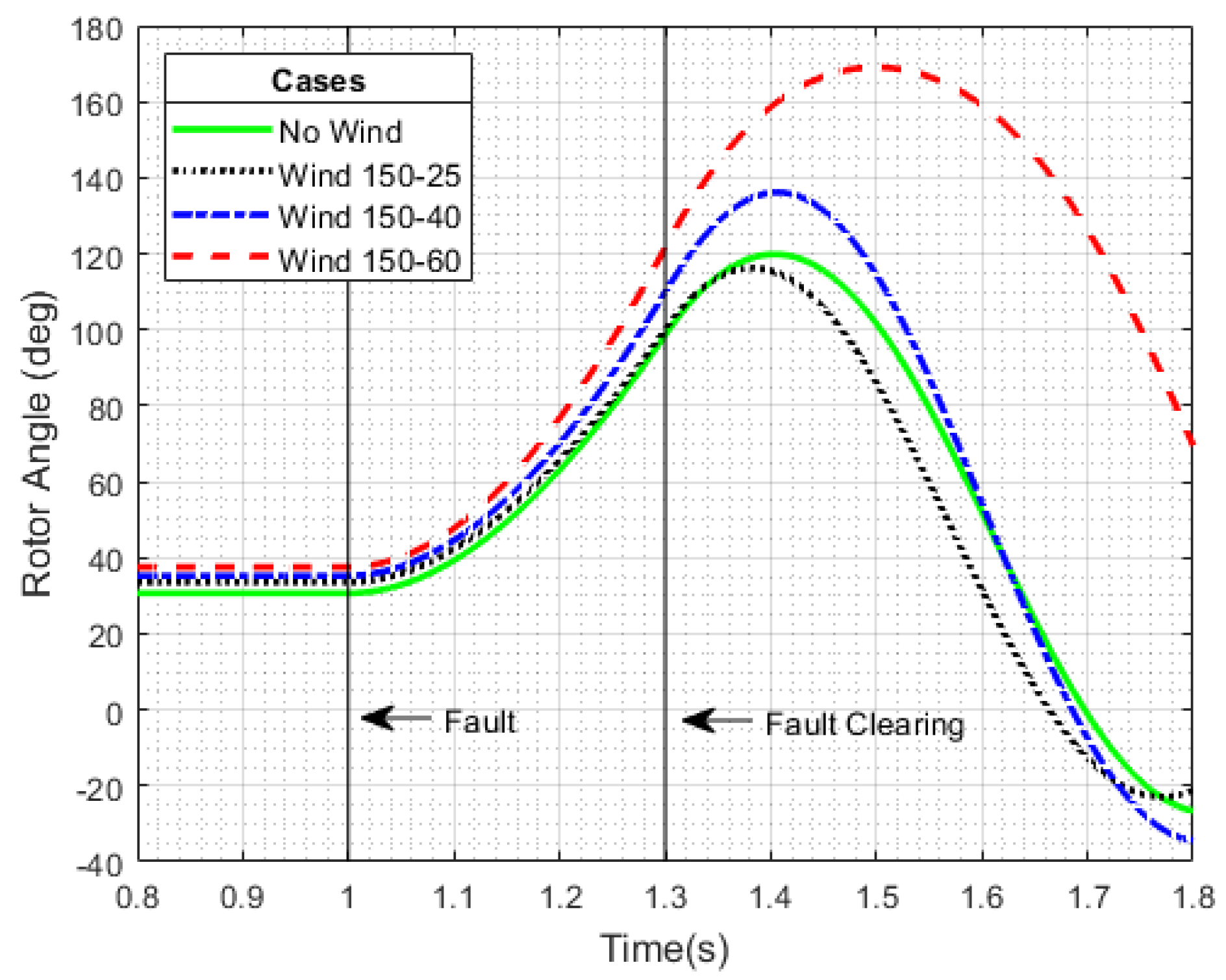
Sensitivity analysis on the share of installed and generated wind power, to evaluate the impacts of the different share on the network following a failure;
An evaluation of the impact on transient rotor angle and frequency stability, through the installation of SVC and STATCOM. These solutions provide TSOs (transmission system operators) and GENCOs (generation companies) with dynamic control during contingencies.
The paper is organized as follows:
Section 2 presents the solutions to improve the transient stability. The studied system is described in
Section 3. In
Section 4, sensitivity to wind position, base power, and injected power is investigated. In
Section 5, the improvement solutions are tested in two different scenarios. Conclusions are presented in
Section 6, where the improvement solutions are summarized, and their main features are highlighted.
3. IEEE 9-Bus System Description
The test system chosen for this study is the IEEE 9-bus system, which is part of a series of test systems often used for studies on the stability, steady state, and dynamics of power systems [
8,
13,
14].
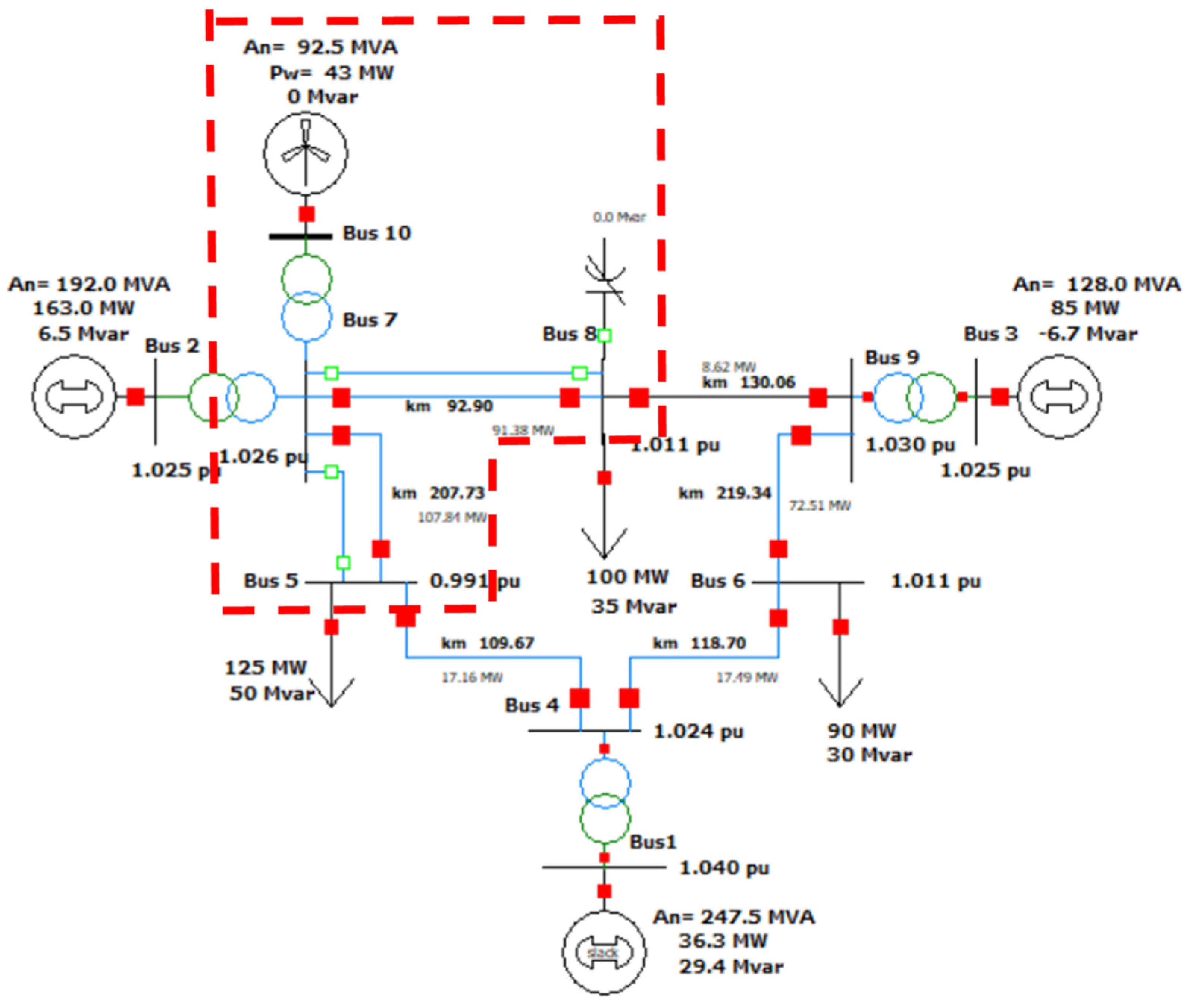
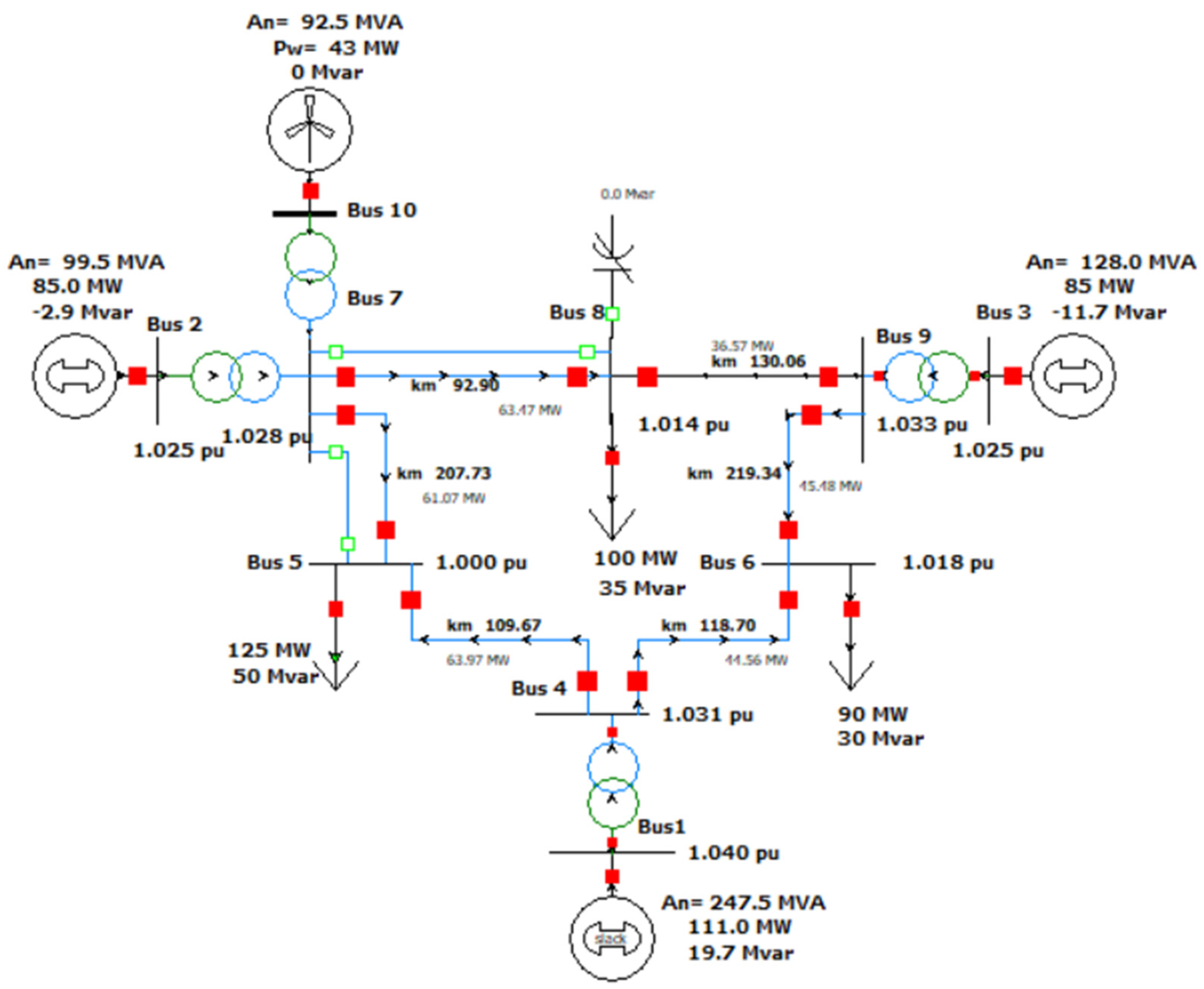
Here, a modified version of the IEEE 9-bus system is proposed. Starting from the modified version illustrated in [
6], one more change is made, i.e., the addition of a type 3 wind turbine generator at bus 7. This is implemented to consider the effect of RES generation in power systems. The location of the wind turbine generator in this node is justified later.
The modified IEEE 9-bus system used in this article is shown in
Figure 1, where the load flow results are shown for the case where the proposed solutions are not used or are switched off. Except for the wind generator, which is always connected, the proposed solutions are alternatively connected. In
Figure 1, the corresponding connections are shown as empty squares. Their connections are also made to study their impact on the system in the different proposed simulations and scenarios.
As in [
6], the transient stability analysis of the proposed system is performed by simulating a three-phase short-circuit. The frequency response of the load is not considered.
According to [
15], the models used, in the PowerWorld Simulator, for implementing the type 3 wind turbine generator, i.e., DFIG (doubly-fed induction generator) wind generator, are shown in
Table 1.
Table 2 indicates the parameters set needed for the chosen control mode.
Here, the analysis follows the steps shown below.
Load-flow analysis is performed to initialize the system;
A three-phase symmetrical short-circuit fault is applied to a transmission line at 1 s;
The fault clearing time, FCT, is set to 0.300 s;
The duration of the simulation is 10 s;
The simulation time step is 5 ms.
5. Simulation on Scenarios
The aim of this study was to assess the impact of wind power generation in terms of stability and the effectiveness of the mentioned solutions to mitigate stability problems caused by the integration of the wind plant. For this purpose, an installed power value of 92.5 MVA was considered within the in-use test system. This value was chosen by applying to our test system the same percentage of wind generation expected from Terna to 2030 within the Italian electricity system [
4].
With the same criterion, a power input value of 42.7 MW was chosen from this wind generator.
Once the generation and production quotas from wind have been defined, the impacts on transient stability related to the use of systems for their enhancement were studied, as seen in [
6].
This assessment was carried out considering two different scenarios:
Scenario A, which provides for the addition of the wind generator without the decrease in the share of conventional generation within the test system, so as not to decrease the inertia value present in the system;
Scenario B, which involves the replacement of a share of conventional installed power equal to 92.5 MVA with wind power, so as to evaluate the impact of the system inertia reduction following the insertion of the wind generator (
Figure 5).
5.1. Scenario A—Wind Added without Replacing Conventional Generation
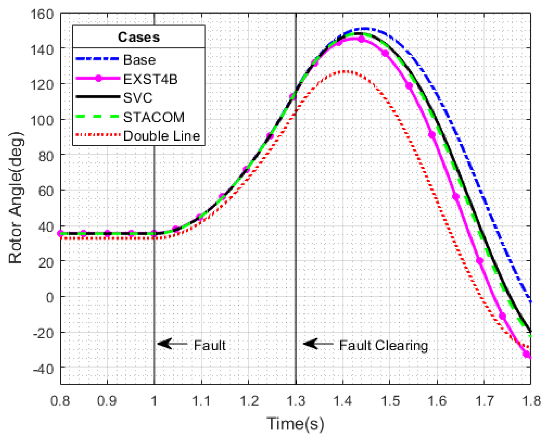
In order to assess the device effectiveness in enhancing stability within the wind-added scenario, the system characterized by the presence of only the wind generator was taken as the base scenario.
Later comparisons were made in terms of rotor angle and CCT with data obtained from scenarios characterized by the presence of a double line, an SVC, a STATCOM, and a fast excitation system EXST4B, as carried out in [
6] and shown in
Table 6 and
Table 7, while the behavior of the rotor angle and the frequency is shown in
Figure 6 and
Figure 7.
The results show that the addition of a new parallel line is the most effective solution to contain the rotor angle variations, as shown in
Table 6 and
Figure 6; moreover, the stability margin was increased by reducing the initial rotor angle, thanks to its effect on the system admittance matrix. SVC and STATCOM (see
Figure 6) had a limited effect on the rotor angle stability, while the fast-acting exciter EXST4B anticipated the maximum rotor angle instant, while also reducing its value.
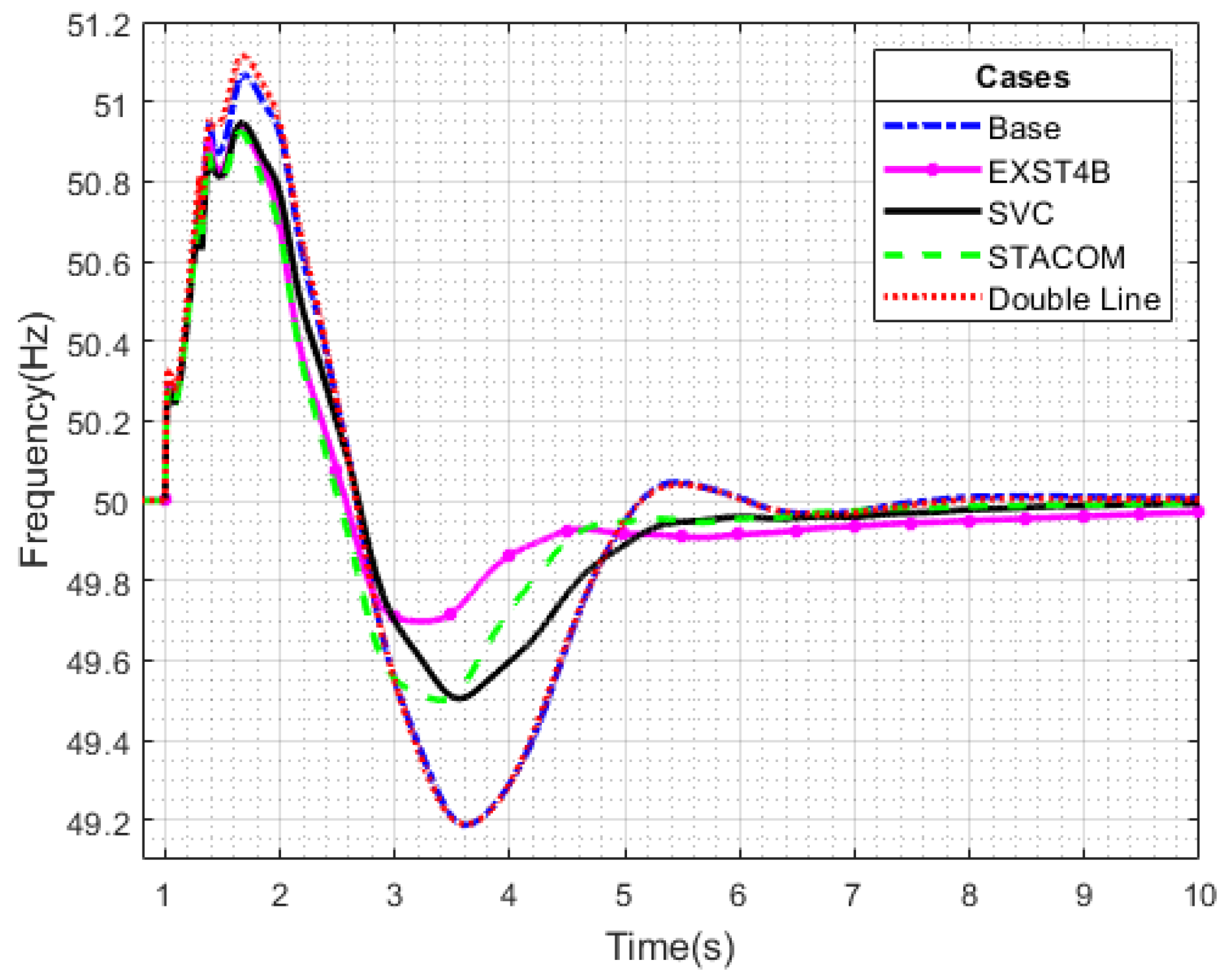
Figure 7 shows that the oscillations occurring in the base caused by the three-phase short-circuit case were mitigated using the solutions considered.
The addition of a parallel line represents a structural and preventive solution, with a small effect on the frequency stability. Emergency solutions such as SVC and STATCOM, as well as the fast-acting exciter, help the system frequency stability, especially during the underfrequency period. This is because these devices operate under dynamic conditions, which allows the control of electrical quantities such as voltage, which is a crucial quantity during a transient caused by a short-circuit. Comparing the results, the fast exciter had the best impact on frequency stability, resulting in the lowest oscillations, reaching the lowest point of 49.65 Hz.
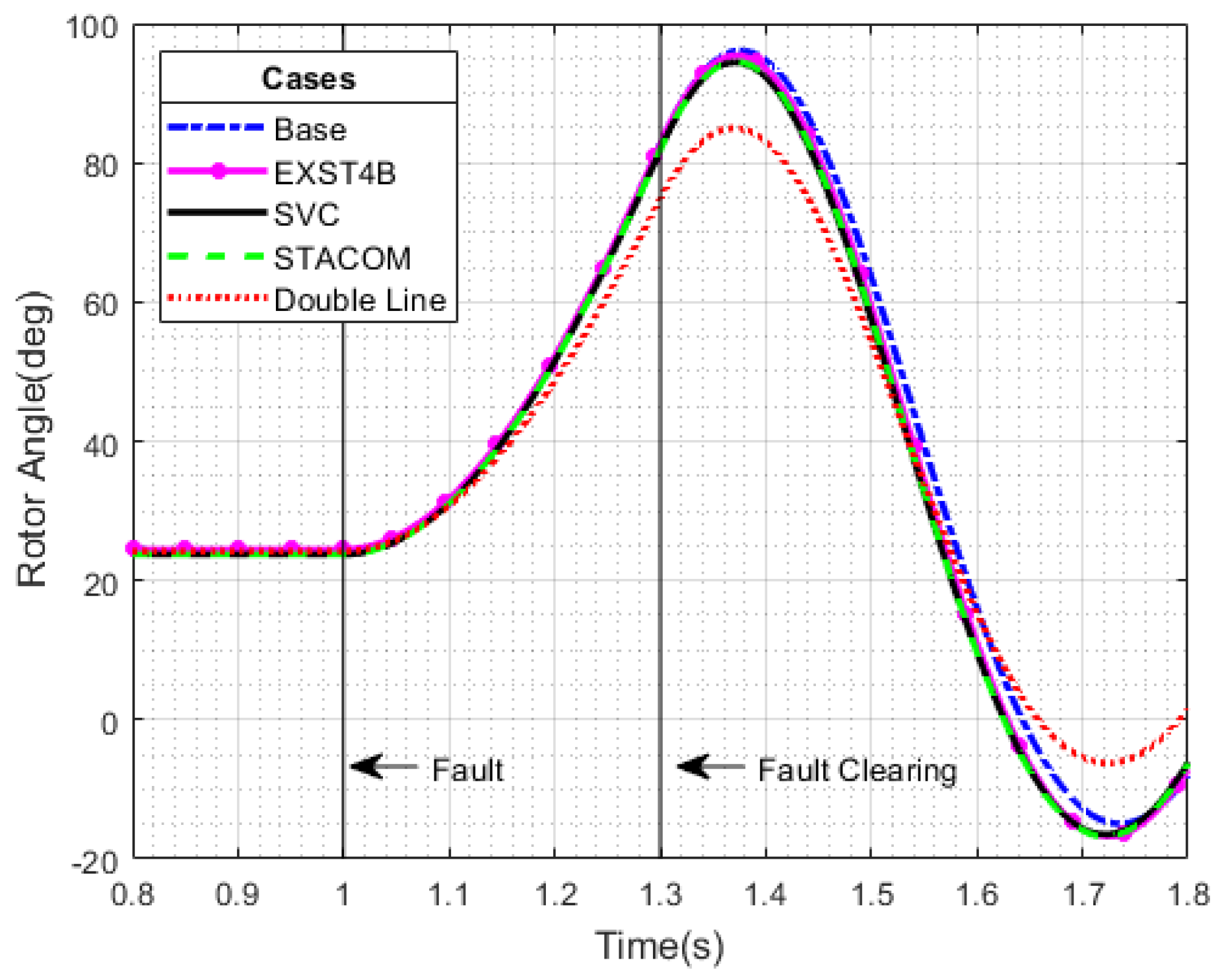
5.2. Scenario B—Wind Added with Replacement of Conventional Generation
The same analyses described in the previous paragraph were evaluated under the scenario that involved replacing the traditional generation quota with wind generation, using the same percentages described. In this case, the effects of the tested devices were also evaluated as a function of the rotor angle and frequency values during the fault, as shown in
Table 8 and
Table 9 and
Figure 8 and
Figure 9.
A look at the rotor angle values obtained in Scenario B (see
Table 8) shows that the maximum rotor angle for each solution was smaller than the rotor angle value obtained for the same solution in Scenario A. The same trend can be observed for CCT in
Table 9. This is due to a different operating point of Generator 2, because the presence of the wind generator allows Generator 2 to feed a lower value of MW to Bus 2.
In the substitute scenario, the best solution for the stability of the rotor angle was the double line and not the other devices, which had only a small effect. The frequency oscillation in the replacement scenario behaved similarly to the addition scenario, confirming that EXST4B was the best solution in terms of frequency stability, reaching a minimum value of 49.7 Hz, as shown in
Figure 9.
6. Conclusions
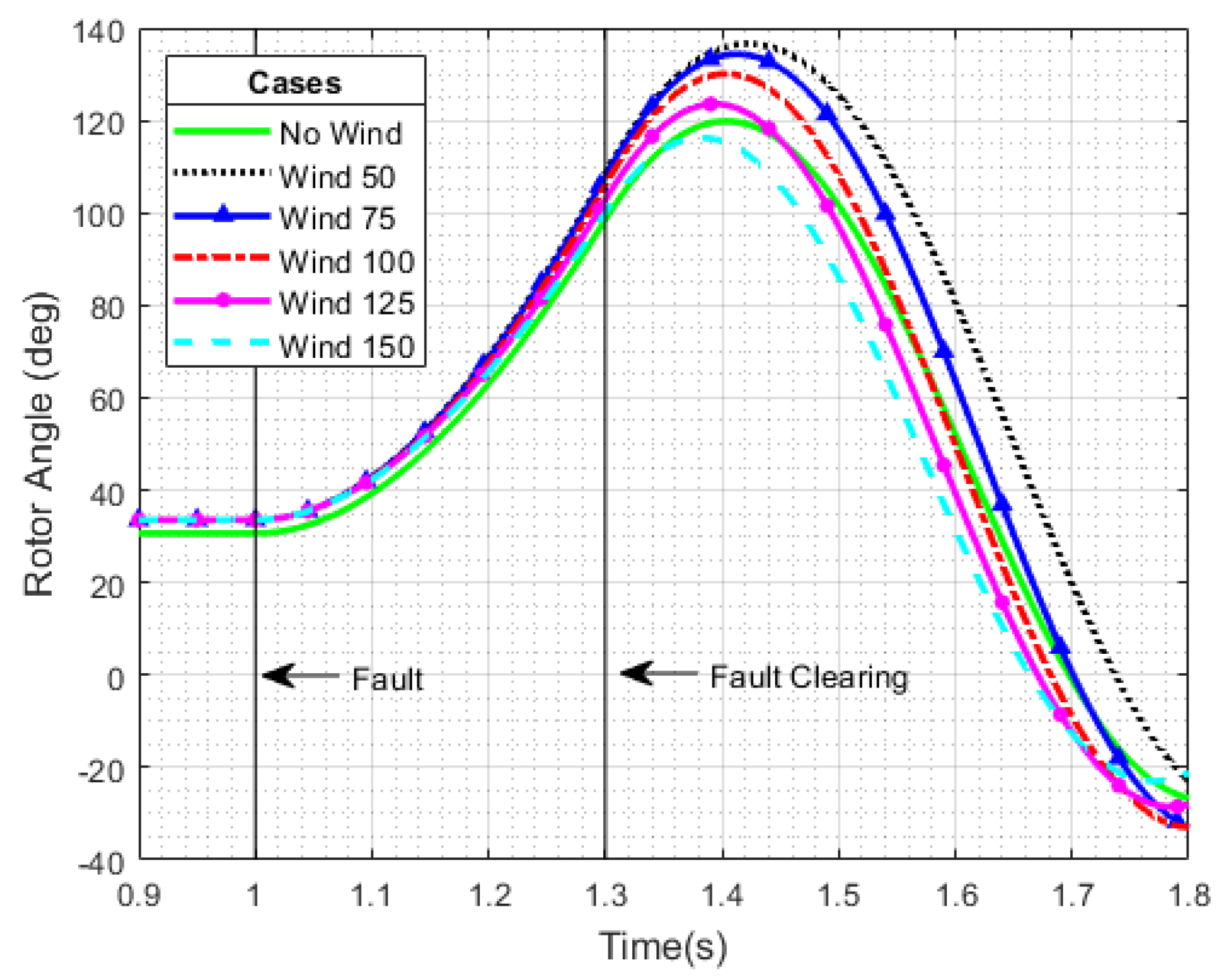
The analyses presented in this manuscript showed that the presence of a wind generator leads to lower system stability, due to inertia reduction, when limited to the grid under consideration. This is true until a very large amount of wind generation is installed (e.g., 150 MVA of wind capacity over 567.5 MVA of programmable generation capacity).
Injected power also affects stability, as an injected power close to the maximum power of the wind generator leads to lower stability margins in rotor angles.
In both the scenario with additional wind turbines and the scenario with replacement wind turbines, the addition of a parallel line (preventive control of transient stability) was the optimal solution to improve rotor angle stability, while the impact on frequency stability was irrelevant, due to the absence of dynamic contribution. In the case of emergency control of transient stability, the fast-acting exciter is the best solution, especially in terms of frequency stability, since it acts faster than any other solution. On the other hand, for rotor angle stability, the fast-acting exciter is useful to improve transient stability, but its contribution is limited with respect to the addition a new parallel line.
SVC and STATCOM showed limited capacity in helping the system to enhance its rotor angle stability, while they represent desirable solutions to improve frequency stability, allowing a better containment of frequency fluctuations, while avoiding the tripping of load shedding relays.
The results can be summarized as follows:
SVC and STATCOM devices provide superior support for improving transient stability. These two solutions show similar behaviors; however, due to their unique features, the STATCOM solution was found to perform at higher standards than SVC—in the case of a weak grid or in a case characterized by a low percentage of synchronous generation (e.g., high penetration of renewable energy sources);
From a monetary/financial point of view, SVC is a cheaper solution than STATCOM, due to its ease of allocation and maintenance, and the larger power range. Investment in these solutions can be economically incentivized for utilities in case of remuneration for reactive power compensation. Focusing on generator companies, an economic incentive, e.g., a remunerated voltage regulation service, could be useful to refurbish their plants and to increase performance through the use of fast excitation systems, as shown in the analyses.
Looking at the next generation of power system structures, specifically characterized by a high presence of RES generation [
8,
14,
17] (which can strongly impact the system stability), it can be useful to reinforce the power grid structure by doubling key lines. This is surely useful to prevent critical congestion problems and significantly improve grid stability.
This paper provides a preliminary examination of the impact of new converter-based technologies on improving the security of modern power systems. Future developments will include the following topics: the impact of different control techniques for thermoelectric generators, concerning only generators with fast valving and brake resistors to mitigate the transient following a contingency. New market products are necessary to push not only utilities to provide services based on new technology, but also TSO to install new devices to manage the future power system safely. This can be achieved, for example, by introducing new ancillary services.


