Article

A Comprehensive Framework for Direct Lightning-Structure-Human Interaction Modelling in Heritage Monuments and Safety Assessment

by
Srisailam Sreedhar
and
Vairavasundaram Indragandhi
*
School of Electrical Engineering, Vellore Institute of Technology, Vellore 632014, India
*
Author to whom correspondence should be addressed.
Energies 2022, 15(19), 7053; https://doi.org/10.3390/en15197053
Submission received: 24 August 2022 / Revised: 22 September 2022 / Accepted: 22 September 2022 / Published: 26 September 2022

Abstract

:
Lightning is a perilous and unavoidable event of nature that presents major deleterious consequences on humans, tall structures, electrical power systems, forests, etc. Though several research studies have been carried out to analyse the sufficiency of a Lightning Protection System (LPS), very few research findings have been reported to assess the extent of risk due to lightning-human interaction in the vicinity of tall structures. This research aims at carrying out detailed modelling and simulation studies of LPS for heritage structure. Several current waveshapes as stipulated in IEC 62305 are modelled appropriately and presented to the electrical equivalent circuit representation of a heritage monument in South India (Brihadisvara Temple) to ascertain the impact of lightning parameters on heritage monuments. In addition, to assess the effectiveness of the earthing system, detailed earthing models during lightning is developed to assess the role played by aspects such as soil resistivity (single and double), earth electrode dimensions, nature of elements in the equivalent circuit, etc. Further, the role of lightning strikes on human due to step and touch potential is ascertained by formulating a lumped electrical equivalent model of human to assess its role and impact on dry and wet skin.

1. Introduction

Among several natural disasters that lead to dangerous consequences, lightning is one of the foremost since damages attributed to such strikes may lead to human fatalities, dilapidated heritage structures, loss of rare forests and fauna, blackout of power systems etc. Lightning strikes are due to the consequence of large transient currents (in the order of several tens of kilo-amperes) [1]. Although various types of lightning such as cloud to ground (CG), ground to cloud (GC), inter-cloud (IC) discharges occur, CG based lightning is the most hazardous to human safety. It is relevant to note that a large proportion of severe lightning strikes are recorded in countries which have a tropical climate [2]. In this context, India has a wide variation in its geographical topology with a large majority of the land mass exhibiting tropical climate. It is also reported that due to advent of the climate change, globally there has been a substantial rise in mortalities due to lightning in recent years [3,4]. The deleterious impact of lightning on building structures such as granite, stone, concrete etc, may have wide variations in its damages such as cracks, chipping-off, buckling etc. In the case of heritage structures the cumulative damages due to lightning strikes may culminate into defacement of rare sculptures and disfigurement of murals whereby leading to loss of rich legacy of rare and ancient structures [5,6].
In addition to the possible damages to significant heritage monuments, it is equally important that the detrimental effects of lightning strikes and the consequent currents that pass through these structures are safely and securely earthed by appropriate techniques by utilizing relevant models related to lightning-based earthing systems [7]. This aspect of heritage structure and human interaction during lightning strikes becomes essential since a few instances of lightning strikes in such monuments have been reported during the past few decades [8]. In [9] it has been observed that lightning strikes in addition to chipping- off the structure of the monument has also additionally presented a likely risk to human safety. Although a few research studies [10] have been carried out to assess the extent of risk on human safety during lightning strikes, such studies have been invariably restricted to power transmission systems and related aspects and have not specifically referred to its perils on humans in the vicinity of heritage monuments. The aspect of lightning-human interaction becomes even more relevant since there is a strong likelihood of devotees resting and staying in the vicinity and premises of the heritage structure [11]. Hence, it becomes vital that the study on lightning-structure-human interaction is thoroughly analysed to ascertain and evaluate the risk of such strikes on human and the probable mechanisms of protection.
Hence, the aim of this research is to carry out an exhaustive analysis of lightning-structure-human interaction based on various well-established electrical equivalent models. This research study involves taking up a specific monument, namely the Brihadisvara temple, which is a United Nations Educational, Scientific and Cultural Organizations (UNESCO) heritage structure since it has been reported to have had incessant lightning strikes during the past two decades. In this research, a framework for lightning-structure-human interaction has been conceptualized and implemented to assess the degree of risk involved due to various classes of lightning currents as stipulated in IEC 62305 standard [12] in order to evolve a mechanism for ascertaining the probable extent of hazard posed to human based on such established models [13]. The first objective of the study is to assess the role of the parameters of the equivalent circuit model of the structure that is implemented during lightning strikes for varying classes of lightning current strokes. The second focus is on analysing and ascertaining the role played by various earthing models in mitigating the current during lightning and the impact of soil resistivity (single and double layer) during strikes. The third aspect of the analysis is to ascertain the impact of lightning strikes based on various mechanisms such as step potential and touch potential and the role played by the effectiveness of earthing in ensuring human safety. The final study is aimed at assessing the lightning-structure-human interaction and the energy expended during lightning due to various mechanisms of lightning and the probable risks associated with each case study.

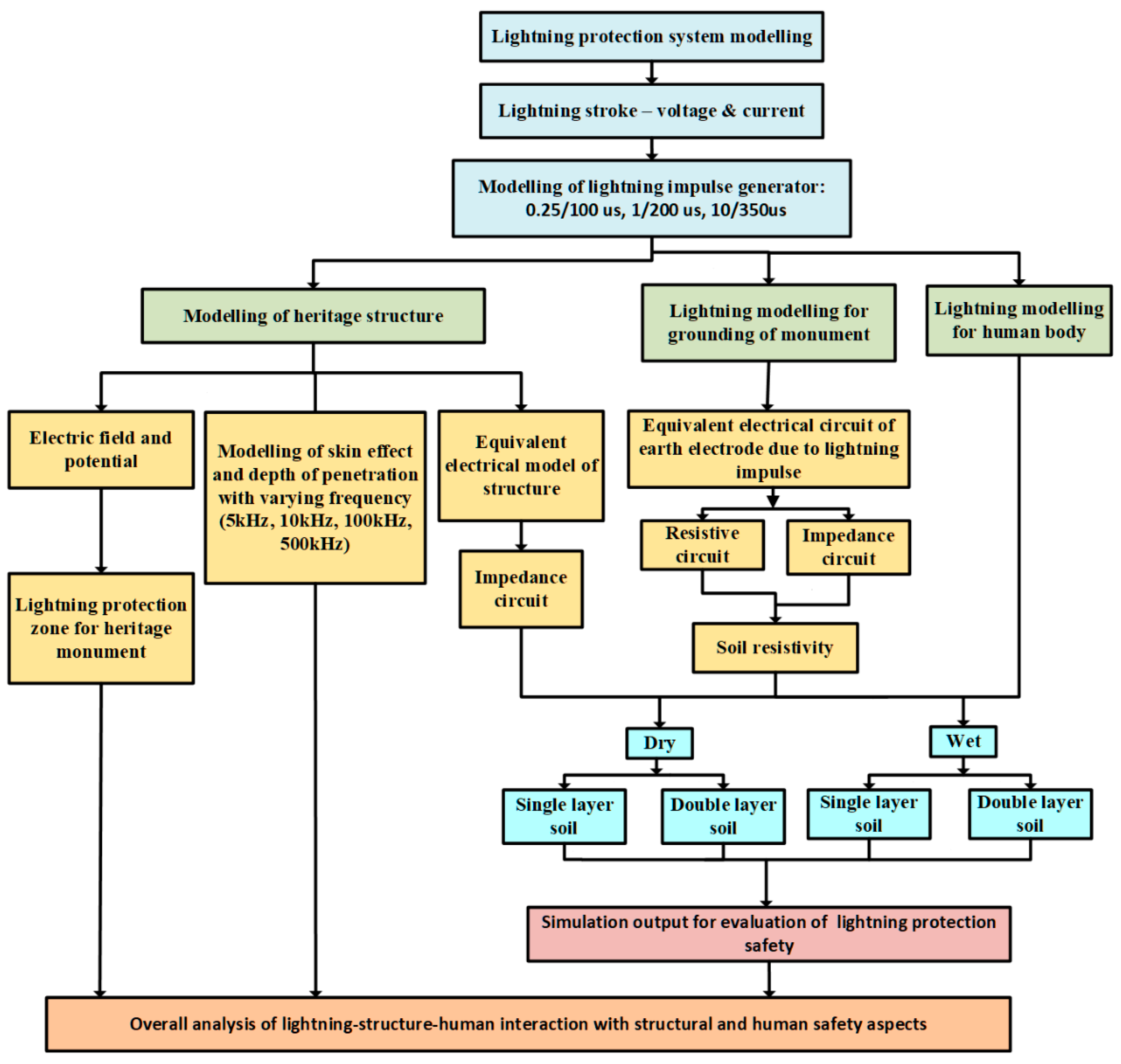
2. Formulation of Framework for Modelling and Analysis of Lightning-Structure-Human Interaction and Electrical Safety Hazards

The framework for implementation and analysis of lightning-structure-human interaction involves three major segments of electrical equivalent model representation namely lightning current stroke, structure, and human. In addition, appropriate modelling for safety earthing for protection from lightning is also envisaged. A lumped electrical equivalent model representation is taken up for implementation during the interaction of the components since these elements are considered to be of finite length and dimensions and the variations related to time are studied based on appropriate ranges of frequency in line with IEC 62305 during the analysis. As a part of modelling the lightning stroke current, a Marx impulse generator is modelled to obtain the various waveshapes (0.25/100 µs, 1/200 µs and 10/350 µs) as stipulated in IEC 62305. Since this research is proposed to carry out on the UNESCO heritage structure located in Thanjavur, India, the soil texture, and characteristics that are considered during this study are based on a mixture of red and clayey soil [14]. Hence, the soil resistivity is modelled based on the location of the structure, wherein, in the case of single layer model approach, a value of 160 Ω-m is considered for the soil under dry conditions while a value of 25 Ω-m is utilized for wet conditions. Since it is also appropriate that due to variations in soil structure which may be attributed to considerable complexities in regions located in tropical climate, a double layer model is also implemented wherein for the implementation of model during dry conditions, a value of 160 Ω-m is considered for the first layer while the second layer utilizes a value of 240 Ω-m. In the case of wet conditions, values of 25 Ω-m and 37.5 Ω-m are utilized for the first and second layers, respectively. It is also envisaged during this research analysis that an LPS with a point earthing system (driven rod) is already installed on the heritage structure as the authors of this research have observed this aspect during their earlier study. Figure 1 depicts the overall framework of the proposed modelling during lightning-structure-human interaction taken up for detailed analysis.

3. Modelling and Implementation of Lightning-Structure-Human Interaction Scheme

Accurate modelling necessitates pragmatic assumptions and boundary conditions during the implementation and analysis of lightning-structure-human interaction for ensuring electrical safety. In this research, modelling, and implementation various aspects namely role of structural equivalent modelling, role, and impact of depth of penetration in structures, lumped R-L-C earthing electrode modelling, role of soil resistivity, impact of lightning in humans based on human electrical equivalent models, and the overall impact of lightning during structure-earthing-human interaction are proposed to be carried out. Some of the major assumptions and boundary conditions include:
  • Standard current wave shapes as stipulated in IEC 62305 namely 0.25/100 µs, 1/200 µs and 10/350 µs
  • Cloud potential in the range of 30 MV to 50 MV
  • Variations in wetness in the range of 20%, 40% and 60% for the case studies
  • Earthing electrode with a length of 3 m and radius of 3 cm
  • The soil resistivity of top layer considered as red soil with resistivity (ρ) during dry condition is160 Ωm and during wet condition is 25 Ωm
  • The soil resistivity of the second layer considered as clay soil with resistivity (ρ) during dry condition as 240 Ωm and during wet condition as 37.5 Ωm
  • Structure material is considered to be granite
  • Human body model with a height of 1.8m

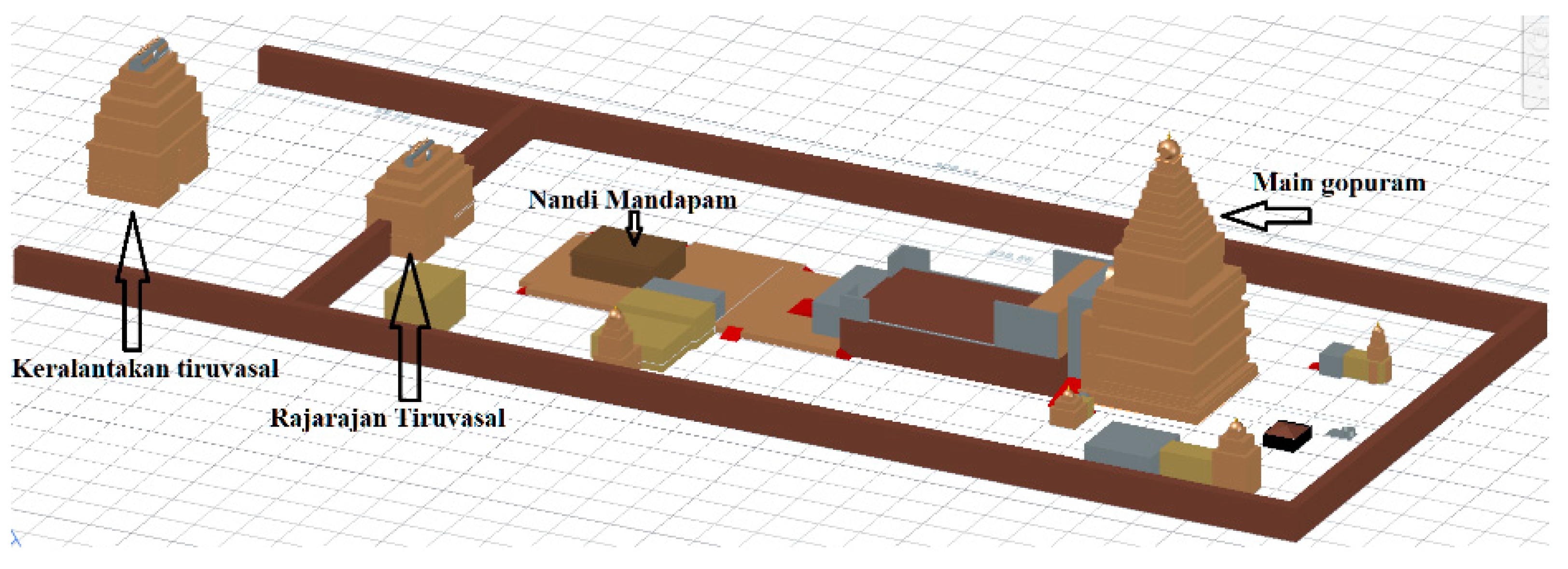
3.1. Modelling of LPS for Heritage Monument

From the context of LPS, during the past several decades, models have been developed for effective shielding based on three types, namely geometric method (fixed angle method), Electro-geometric method (Rolling sphere method) and mesh method. The RSM has been widely accepted and stipulated method in international and national standards [12,15] for protection of tall structures and hence implemented in this research.
The Big temple, a tall heritage monument which is located at southern part of India, is also a UNESCO property and has been taken up for research study to estimate the protection of pre-installed LPS. The main gopuram (also known as vimana, where the deity resides) is built with granite using interlocking system and have dimensions of height 60 m and width of 24 m. The structure is drawn in 3D using AutoCAD and the layout is depicted in Figure 2.
It is pertinent to note that there have been incessant lightning strikes on the Big temple during the past few decades with significant damages to the heritage structures. It is also observed that LPS has been installed in such structures, though partially in recent times [11]. Notwithstanding, damages due to strikes on structures continue to challenge the research community involved in protection of structures from lightning which may be attributed to the stochastic nature of lightning attachment phenomenon [5], ineffective grounding system, improper location, insufficient number of lightning rods, lack of credible records related to shielding failure analysis, etc.
During the preliminary studies carried out by the authors of this research in [11], it has been observed that the existing LPS involves a lightning rod installed on the top of the main gopuram while the second is installed atop the corner of the entrance gopuram (Keralanthakan gopuram). In this context, the structure is taken up for the analysis of lightning protection zone according to the methods stipulated in IEC 62305. As the structure is taller than the specified limits of the Fixed Angle method (60 m as specified in the standard), this method of analysis is not considered for analysis. Hence, the RSM is taken up for modelling the zone of protection. In this method, an imaginary sphere with radius of lightning strike is being rolled over and around the structure, wherein, the area covered under the sphere is the zone of protection [16]. The safe and protected volume under a building or structure from lightning strike may be ascertained based in the shadow region exhibited by the sphere rolled over and around the edifice. This method also helps in identifying the vulnerable points which necessitates lightning rods for additional protection. The striking distance is calculated using
R a = 8 I 0.65
where R a is the attractive radius in m and I is the peak lightning current in kA.
Assuming that the LPS is installed for level IV peak current of 100 kA, as per IEC 62305 and based on the iso-keraunic level of the region, the sphere with radius 60 m is drawn over and around the structure to estimate the protection zone of the installed LPS and is represented in Figure 3. The zone of protection estimated with the LPS shielding is depicted with green while the unprotected is circled with red.
From Figure 3 it is observed that LPS installed on the monument is not providing effective zone of protection for the peak lightning current of level IV as stipulated in the standard IEC 62305 and obviously becomes clearly insufficient for the higher current levels III (for 100 kA R a = 30 m), II (for 150 kA R a = 45 m) and I (200 kA R a = 20 m).
It is extremely significant to note that these studies become pertinent from the context of lightning interaction with structure, as inadequate protection related to risk indices for heritage structures may lead to consequent hazard to human safety. Hence, implementing an effective protection zone during this research study is the first step, yet the most essential one towards ensuring human safety during lightning strikes.

3.2. Modelling and Implementation of Heritage Structure during Lightning Strikes

A few research studies have been taken up in recent times to simulate the electric field profile and modelling of heritage structures [10] during lightning. Such studies have focused on probable impact of lightning on specific locations of the monuments and mechanism for mitigation from such strikes. Such studies also include the conception and implementation of electrical equivalent model representation of structures. In this research, this aspect is utilized to model the main vimana of the Brihadisvara temple to enable the assessment of the impact of varying waveshapes during lightning stroke currents.

3.2.1. Estimation of Electric Field and Lumped R-L-C Parameters of Structure

The main vimana of the temple has been modelled using COMSOL® Multiphysics as a three-dimensional (3-D) layout. To analyse the electrical properties of the structure and estimate the drop in the potential, the structure is drawn in 3D as depicted in Figure 4.
The structure is simulated by considering the material as a composition of granite blocks with electrical conductivity ( σ ) of 0.0001 and relative permittivity ( ε ) of 6 [17] considered as input values for the simulation. The simulation is performed by applying 45 MV at the tip of the gopuram and the field plot is depicted in Figure 5. During the steady-state analysis, the magnitude of electric potentials at respective heights of the Vimana are plotted in Figure 6.
To obtain more appropriate and accurate values of R, L and C of the monument, the structure is divided into 15 tiers, since it is obvious that the structural material used in the monument (granite rock) might have varying homogeneities in its chemical, physical, electrical and mechanical properties. The values of R, L and C can be estimated by utilizing the formulae [18]
R = ρ l A    
L = 2 × 10 4 l [ ln 2 l ( w + h ) ] + 0.2235 [ w + h l ] + 0.5     μ H
C = ϵ A d   F
Table 1 summarizes the values of R, L and C estimated and computed for each tier of the main vimana based on the Finite Element Analysis (FEA) and the consequent to the electric field profile analysis carried out using COMSOL.
As discussed earlier in this section and based on studies carried out by a few researchers [18] the generic equivalent circuit is depicted in Figure 7.

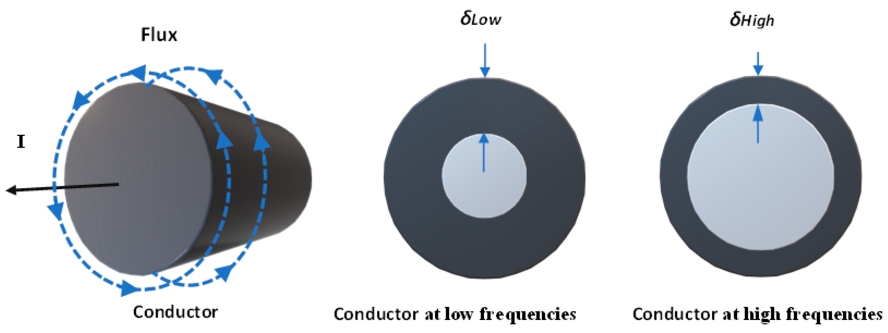
3.2.2. Modelling of Depth of Penetration during Lightning Strikes

Skin effect is a phenomenon, wherein at low frequencies, the current is distributed uniformly over the cross-section of the conductor, while at higher frequencies, the current is not distributed uniformly and tends to flow with higher density through the surface of the conductor rather than the core. The pictorial representation of skin effect is depicted in Figure 8, which illustrates the depth of penetration in a conductor due to low frequencies and high frequencies. Research studies based on transmission line modelling [19] and consequently the propagation of transverse magnetic waves along a conductor [20] (in this case, the structure) have indicated the role played by the skin effect and hence skin depth ( δ ).
In this research work, the structure is assumed to have been hit by direct lightning stroke to enable in ascertaining the behaviour of skin effect and estimate the depth of penetration. A generic representation of this scenario is indicated in Figure 9, which depicts a radiated magnetic field around the structure during lightning.
Recently, studies to ascertain the skin depth in heritage structures have been carried out for a range of lightning frequency spectrums in line with IEC 62305 and as indicated in [18]. Furthermore, such studies have also computed and analysed the typical skin depth of mortars with limestone in structures at a frequency of 10 kHz, which was observed to be about a few meters (6 to 8 m) with the resistance of the mortar slabs being a few hundred ohms.
Since the skin depth ( δ ) is directly related to the depth of penetration of the lightning current during a prospective strike to a heritage structure, it is evident from Equation (5) that electrical conductivity plays a vital role in evaluating its heating and thermal withstand capability.
δ = 2 ρ ω μ 1 + ( ρ ω ϵ ) 2 + ρ ω ϵ  
where ρ is the resistivity in Ω-m, ω indicates the angular frequency and µ denotes the absolute permeability of the structural material taken up for analysis.
At frequencies much below ( 2 μ ϵ ), the formula gets simplified as
δ = 2 ρ ω μ
In this research, the main vimana has been modelled using MATLAB PDE toolbox to simulate and estimate the depth of penetration of lightning of the structure at varying frequencies. The Dirichlet boundary condition is assigned for the gopuram while the Neumann condition is assigned to the grounded portion of the structure. The solution to the second order partial differential Laplace equation is carried out based on the mesh solver of the toolbox to enable in displaying the role of frequency and its penetration in the structure. Figure 10a shows the formulation of mesh using Finite Element Method (FEM) while Figure 10b displays the electric field plot that indicates the role of depth of penetration at 500 kHz.

3.3. Modelling of Earthing System during Lightning

Earthing system is the most important aspect for an effective LPS due to its role in providing a quick path to short circuit (large transient fault) current by providing the least resistance. Earthing is significantly different for varying nature of voltage sources (power frequency and lightning) as the frequency is considerably different in each case. During the period of lightning, the frequency varies from a few kHz to MHz [21], wherein, the resistance value is not altered significantly due to the shape and dimensions of the lightning waveform. It is evinced from research studies that it is ideal that the earthing resistance is brought down to as low a value as possible and invariably made to be at least less than 10 Ω [22]. In this context, it is pertinent to note that modelling of earthing system for lightning protection needs to be viewed from two broad aspects, namely earth electrode and soil resistivity representation during the implementation of this research.

3.3.1. Modelling of Depth of Penetration during Lightning Strikes

Though two major grounding arrangements namely horizontal and vertical configurations of earth electrodes are utilized, the vertical ground rods are one of the simplest and most used methods for earth termination of electrical and lightning protection systems for standalone structure and isolated buildings. On the other hand, the horizontal grounding arrangement (interconnected mesh) is more popular and appropriate for power system applications wherein the objective is to ensure safety of several interconnected electrical apparatus. In this context, the behaviour of vertical earth electrode at static frequency (50 Hz or 60 Hz) has been widely analysed and implemented by power utilities and end users based on static approximation. By convention it is evident that at low frequencies, ground impedance of a single vertical rod is represented by a single resistor while at considerably much higher frequencies the electrical equivalent model may better be represented by a suitable combination of a lumped RLC circuit, as depicted in Figure 11 [20]. The expressions of lumped ground resistance (R), inductance (L) and capacitance (C) for a vertical rod are given by,
R = ρ 2 π l A
L = μ 0 l 2 π A
C = 2 π ε l A
where A = l n 4 l a 1 , l and a are the length and radius of the rod respectively.
The parameters of the RLC circuit may be used to approximate the per unit length values of a distributed-parameter circuit and indicate by
R = 1 G = R l   ( m )
L = L l   ( H m 1 )
C = C l   ( F m 1 )
Since the model of the earthing electrode system using the distributed circuit approach involves representation of a transmission line as the conductor (electrode as a conductor), the conductor model may be open at the lower end, and the input impedance (equivalent to the harmonic ground impedance) is given by
Z ( ω ) = z 0 c o t h γ l
where γ = j ω L 1 ( G 1 + j w C 1 is propagation constant and Z 0 = j ω L 1 / ( G 1 + j w C 1 is characteristic impedance.
It is evident from [2,3] that high frequency grounding behaviour may be categorized as inductive when | z ( ω ) | R > 1 , resistive when | z ( ω ) | R 1 and capacitive | z ( ω ) | R < 1 . Resistive and capacitive behaviour is more conservative because the high-frequency impedance is equal to or smaller than the low-frequency resistance to earth and consequently grounding of high frequency performance is the same or better than at low frequencies. The possibility for providing good high-frequency performance is to use smaller electrodes with capacitive or resistive behaviour.

3.3.2. Modelling of Resistivity of Soil Layers

Several studies have been undertaken by researchers for obtaining a credible and reliable estimate of the soil resistivity for computation of earthing system. In this context, IEEE 80 has provided various procedures and methodologies to model resistivity based on the homogeneity and texture of the soil. Such studies clearly indicate the methods of modelling the soil and hence involves two broad categories namely single layer and double layer approaches.

Single Layer Model

This approach involves representing the soil as a uniform homogenous layer for the estimation of earthing resistance, inductance, and capacitance. The computation of soil resistance, inductance and capacitance are based on values given by
R = ρ l a
where ρ is the soil resistivity of the soil, l is the length of the earthing rod and a is the radius of the earthing rod.
L = μ 0 l 2 π
C = 2 π ε l l n 4 l a 1
In this research work, the nature of the soil is reported to be of red type and hence modelled as a single layer representation of its resistivity as160 Ω-m during dry condition and 25 Ω-m during wet condition. For the values of resistivity considered, the grounding resistance is estimated to be 50.835 Ω during dry condition and 7.94 Ω during wet condition. Similarly, the capacitance is estimated at 10 pF where the inductance is 3.6 µH.

Double Layer Model

A non-homogeneous soil with two layers (the first layer is red soil; the second layer is clay soil) are modelled for the study in line with the stipulations laid out in IEEE 80 [4] with a soil resistivity of 160 Ω-m for the first layer and 240 Ω-m for the second layer during dry condition (25 Ω-m for the first layer and 37.5 Ω-m for the second layer during wet conditions).
For the two-layer soil model, the resistance of the earth rod and soil resistivity is estimated from
k = ρ 2 ρ 1 ρ 1 + ρ 2
The resistance for the grounding rod is calculated by
R = ρ 1 2 π l l n 2 l a + n = 1 K n l n 2 n h + 1 2 n h 1
where h is the height of the soil layer
Based on the computation carried out during the proposed analysis, total resistance of the rod is estimated to be 44.857 Ω during dry condition and 6.9148 Ω during wet condition.

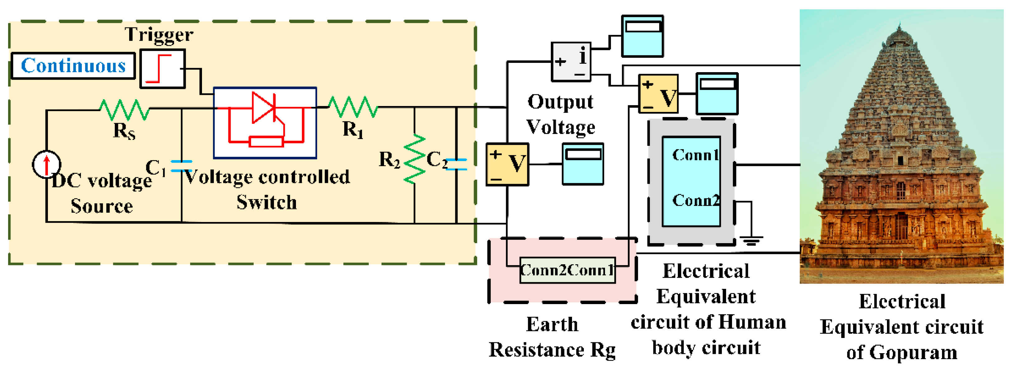
3.4. Implementation of Lightning Stroke Model for Simulation of Voltage and Current Waveshapes

3.4.1. Generic Aspects of Lightning Impulse generator Modelling

Lightning is a high voltage impulse which occurs for extremely short durations varying from a few microseconds (µs) to milliseconds (ms). Though several models for simulation of lightning strikes have been utilized by researchers over the years, a simple Marx impulse generator circuit [23] is proposed for generating high impulse voltages and currents in this research study. The principle of operation of the Marx circuit is based on charging the capacitors in parallel and discharging them in series by triggering a switch (sphere gaps) in large laboratories to simulate lightning impulse waveshapes of standard configurations in line with the stipulations laid out by IEC 62305. Figure 12 shows the wave shaping components (resistors and capacitors) wherein the front-end resistors and the discharge resistors are distributed along each stage. During the implementation, a high voltage source is used to charge the capacitors in parallel. In laboratories the sphere gaps which serve as an excellent voltage-dependent and voltage-sensitive switches are in turn connected in parallel to the charging capacitors which when the sphere gaps spark across, discharge in series. The charging current is limited by a large charging resistance which is typically of the order of a few hundreds of kilo ohms. On firing (or triggering), the lowest sphere gap (stages 1 and 2) becomes connected in series. Hence, the individual voltages across stages 1 and 2 appear as a sum across the next gap, thereby triggering it and thus connecting all the stages in series. Hence, an impulse voltage is obtained across the load (which is modelled as a dielectric or capacitance).

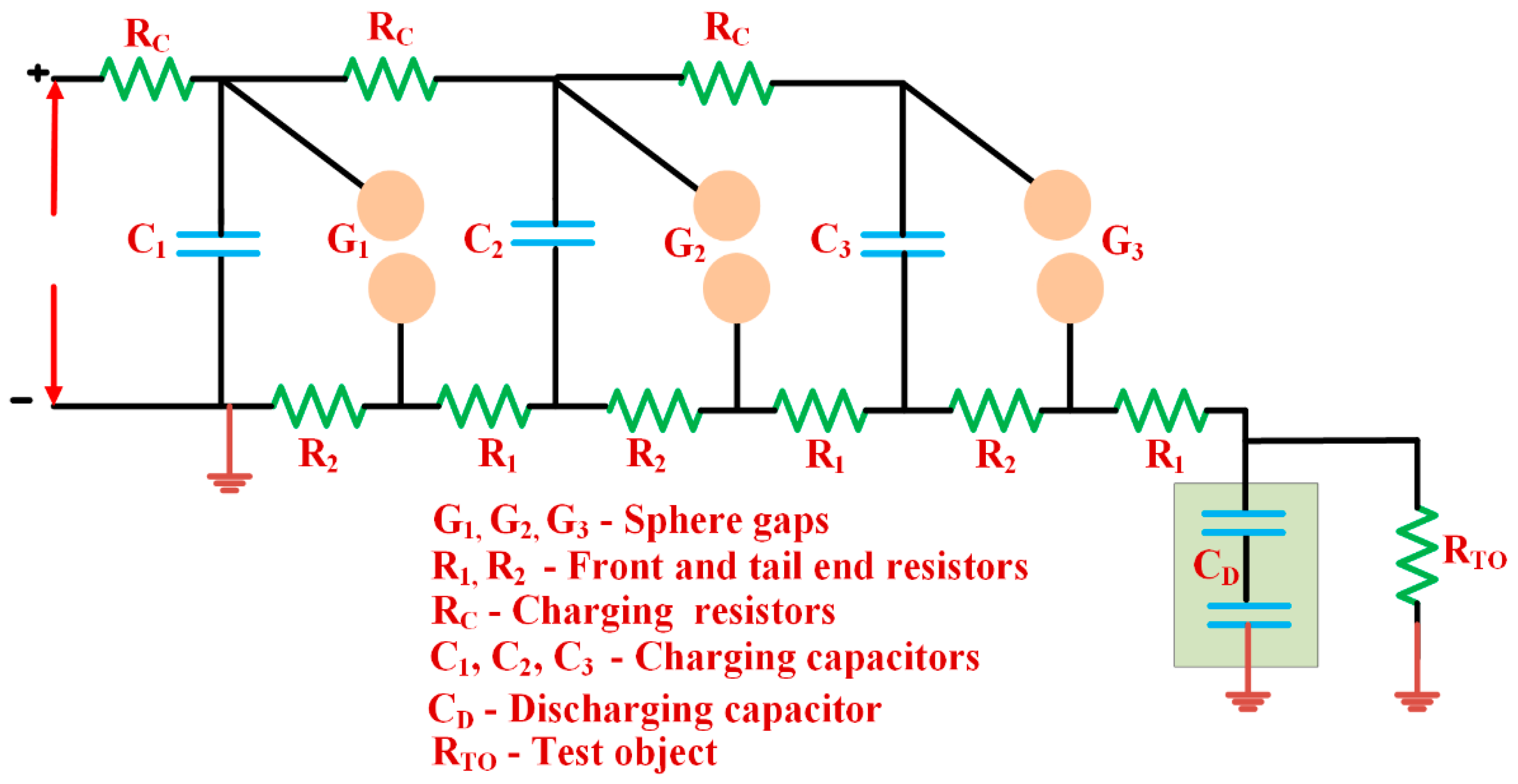
3.4.2. Modelling and Implementation of Marx Impulse Generator as per IEC 62305

In this research, the authors have considered three waveshapes according to IEC 62305 i.e., 0.25/100 µs, 1/200 µs and 10/350 µs. Figure 13 represents the model of Marx impulse circuit taken up for simulation circuit using MATLAB.
Table 2 summarizes the values of wave shaping components (R1, R2, C1 and C2) utilized for generating various standard waveforms.
Typical waveforms of the lightning impulse voltages obtained during the simulation studies are depicted in Figure 14.

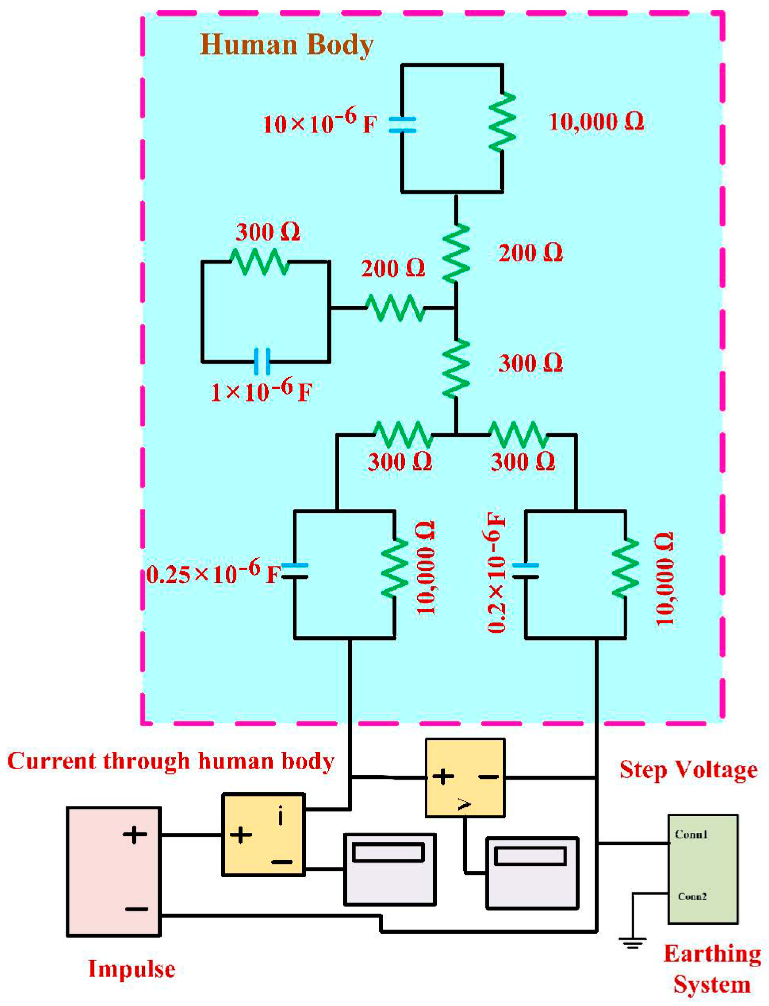
3.5. Human Body Model

In recent times advanced studies have been undertaken to assess the impact of lightning strikes on humans utilizing voxel-based modelling [24], ellipsoidal models [25] etc. However, since this research focuses on obtaining a quick index of the risk of human during lightning, a lumped human model as proposed in [8] has been taken up for implementation since detailed analysis with a high accuracy at a microscopic level inside the human body due to the impact of lightning currents during strikes are not a specific part of the scope of this research and hence needs to be seen from the context of a more conservative measure.
In this context, the lumped electrical equivalent human model for lightning involves representation of several cases namely direct lightning strikes, step and touch potential, Ground Potential Rise (GPR), telephone mediated strikes etc. The generic pictorial illustration of the human-lightning interaction in heritage monument is indicated in Figure 15. Specific cases related to the step and touch potential, which is taken up for detailed analysis during this research, is based on the aspect indicated in the layout.
During leader propagation, charge accumulates at different points of the human body, including the head and the built-up voltage on the head of the human in turn taken is to be V ( t ) [26]. The current through body can be computed as
I b o d y ( t ) = V ( t ) Z H D + R N + R B + R L + Z F 2 + R C o n
where Z H D is the impedance of the head, R N is the resistance of the neck, R B is the resistance of the body, R L is the resistance of the leg, Z F is the impedance of the foot and R C o n is the contact resistance between the foot and the actual ground (zero potential).
In order to analyse the impact of lightning parameters of humans, the lumped circuit model representation as indicated in Figure 16 coupled with RLC circuit of the temple gopuram along with an impulse generator circuit representing induced voltage is proposed for implementation and simulation of various lightning-structure-human mechanisms in order to obtain and compare the current through the human body for several case studies.

3.5.1. Touch Potential

When the LPS installed on the main vimana is struck by lightning, current will flow through the down conductor and a corresponding voltage would be built up at the point of contact of a human (usually at 1.5 m from the ground). If the impedance of down conductor ( Z D C ) is represented by the series connection of down conductor resistance and inductance together with earth resistance ( R E ) representing the buried earth electrode, the voltage at the touch point can be computed as
V ( t ) = I ( t ) [ Z D C + R E ]
where I ( t ) is a typical 10/350 µs lightning current wave shape as stipulated in line with IEC 60060 [27].
By considering the human lumped RC model representation during lightning, the current through the human body can be calculated from
I b o d y ( t ) = V ( t ) Z H D + R N + R B + R L + Z F 2 + R C o n
where R C o n is the contact resistance between the foot and the actual ground considered as zero potential, which includes the resistance of the soil.

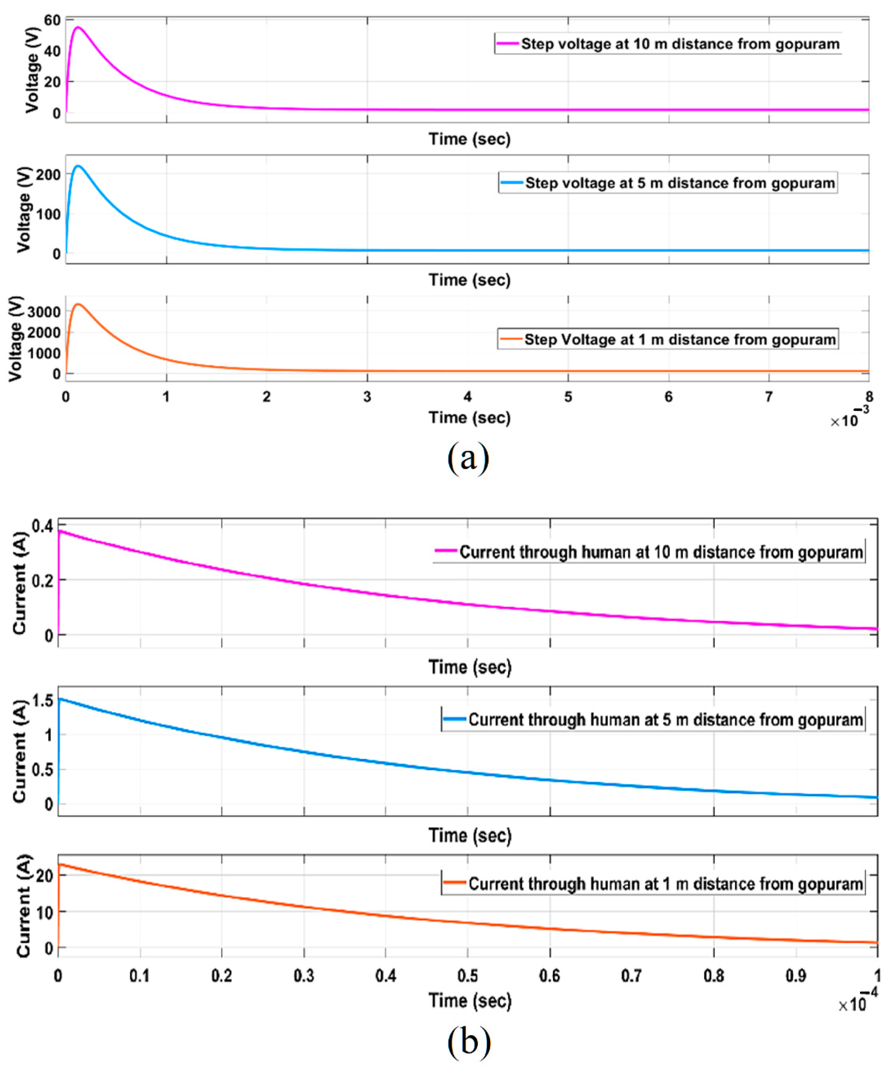
3.5.2. Step Potential

When the lightning current flows to the ground, the ground potential at the striking point rises instantaneously and decays along the surface of the flow. Hence, a voltage drop (ΔV) is induced across the legs of the human. Thus, the current flowing through the body can be written as
I b o d y ( t ) = V ( t ) 2 ( Z F + R L )

4. Observations and Analysis of Lightning-Structure-Human Interaction Modelling for Heritage Monuments

Detailed analysis has been carried out for five major case studies to determine the impact of lightning strikes on structure and its interaction with humans. The objectives of the case studies are to ascertain the role played by material properties of structure, effectiveness of earthing system and human physiological aspects in relationship to variations in lightning parameters.

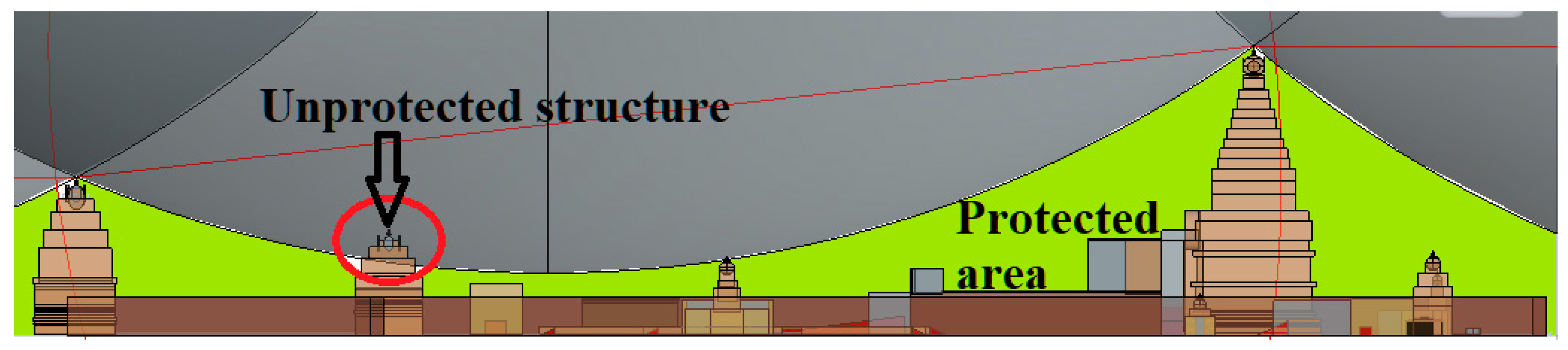
4.1. Analysis of Zone of Protection

As discussed in the Section 3.1, it is evident that the LPS installed on the structure is insufficient for the levels of protection stipulated in IEC 62305 and the same is cross validated using SESHIELD 3D® for 100 kA, which is depicted in Figure 17a, wherein the area shaded with green colour represents the protected zone and the contour displayed in ‘red’ is the unprotected zone. In this context, the authors have identified a few vulnerable corners and edges which require additional LPS. Such locations include the corners of parapet walls of the main vimana, non-existent air terminal atop the second tower (Rajarajan gopuram) and insufficient lightning rods installed on top of the entrance gopuram (Keralanthakan gopuram). Considering these shortcomings, a detailed simulation has been carried out by incorporating the additional lightning rods at those vulnerable points to assess the area covered under zone of protection which in turn has been cross validated using SESSHIELD 3D. The results are depicted in Figure 17b, which clearly indicates the improved zone of protection covering the entire heritage monument.
It is evident from the analysis that insufficient protection has probably led to the recent strikes on the heritage structures as reported in [11]. In addition, the risk analysis indicated in [11] reasonably validates this claim. It is hence pertinent from the analysis that effective LPS is a prerequisite to ensure structure-human safety. Hence, the shortcomings in the existing LPS have in fact inherently a key aspect of concern, which has in turn motivated the authors to carry out detailed studies on structure-human interaction during lightning strikes.

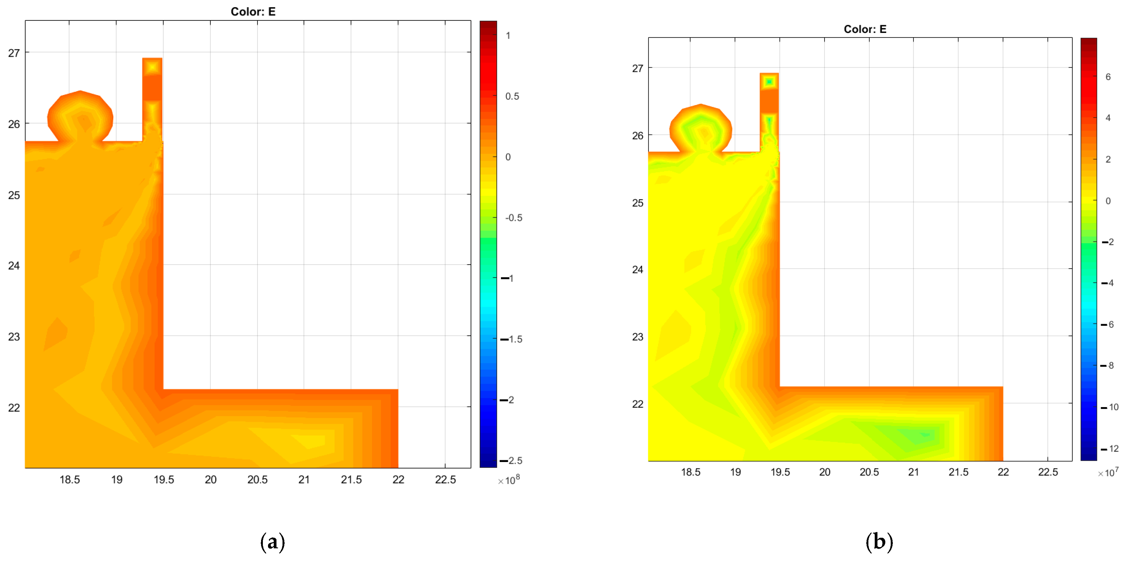
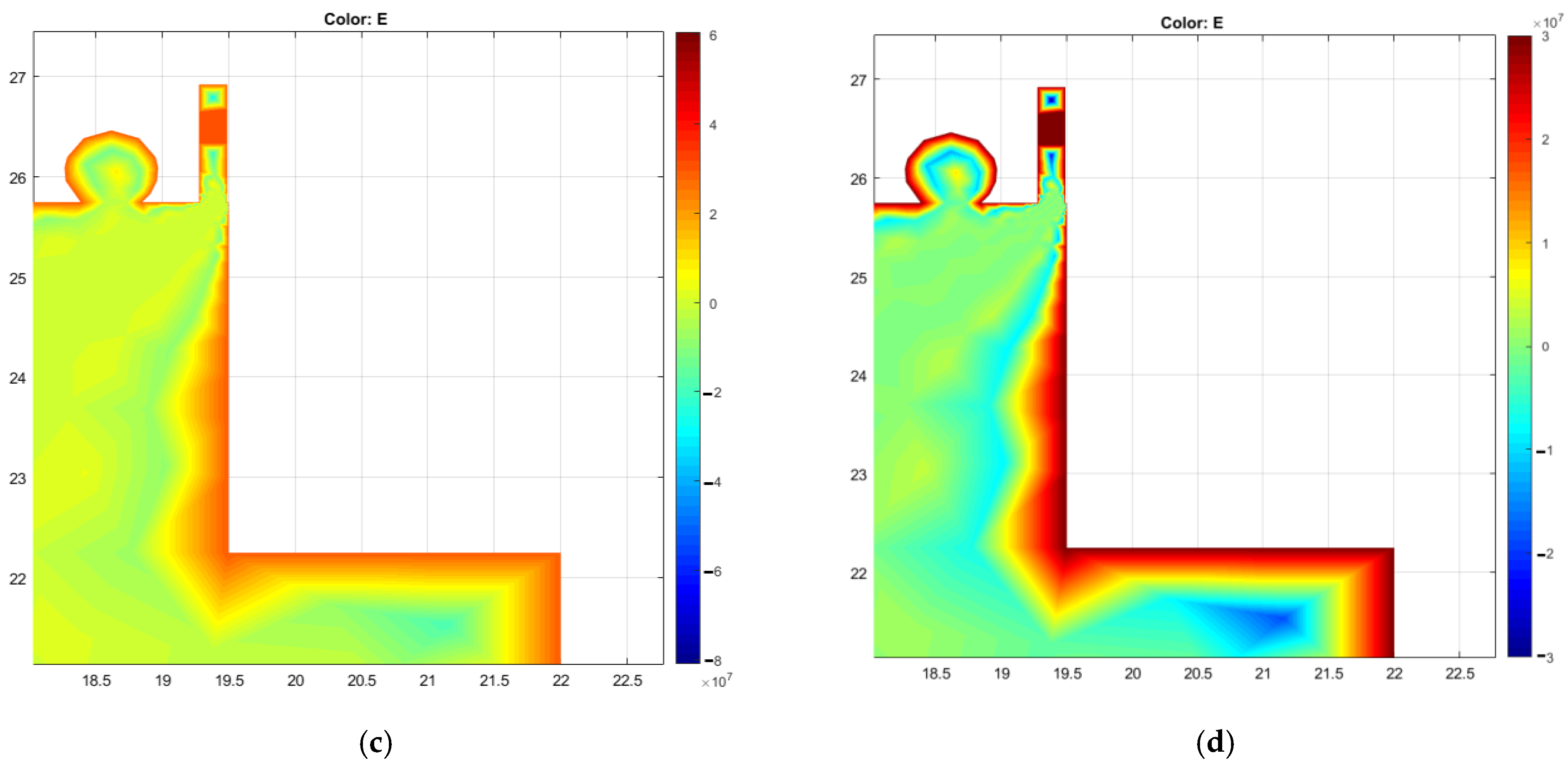
4.2. Analysis of Impact of Skin Depth

During thunderstorm, when the main Vimana is hit by lightning, substantial electro-magnetic forces are exerted over the structure, causing severe stress at the point of strike. From the context of the profile of the structure and its layout, gopurams in temples have been built with exquisite sculptures of human and real-time images which inherently involve several edges and corners, whereby becoming vulnerable points to lightning strikes. From the simulation of skin effect for the main gopuram as depicted in Figure 18, it is evident that such corners are prone to direct lightning strikes causing structural damages with a depth of penetration of material depending on the lightning frequency. The frequency of electro-magnetic waves propagated during lightning strikes in the simulation studies has been suitably varied in the range of 5 kHz to 800 kHz, since researchers in [28] have indicated variations within these stipulations. Table 3 summarizes the magnitude of depth of penetration for varying frequencies.
It is observed from such studies that a depth of penetration in the range of about 0.3 m to 1 m is indicated in the electric field plot at a few critical locations of the proposed structure.
Though lightning strikes and subsequent reports of damages in main Vimana have not been recorded, similar strikes on Rajarajan gopuram and more recently the Keralanthakan gopuram have been reported and shown in Figure 19. Studies carried out by the authors of this research earlier also reiterate this aspect. It is evident from the present study that the depth of penetration of the yazhi sculpture, atop the Keralanthakan gopuram is very much in the range as made evident in the electric field plot, as depicted in Figure 20a–d for various ranges of frequencies.

4.3. Analysis of Importance of Soil Resistivity and Lumped R-L-C Earthing System

To study the behaviour of the structure during the instance of direct lightning stroke, software-based simulations using MATLAB Simulink have been carried out in this research by implementing a circuit comprising an impulse current generator, a lumped RLC equivalent circuit of gopuram and an earthing system. A generic circuit of the simulation is depicted in Figure 21.
An appropriate value of electric potential based on the variations of cloud height is taken up in the range of 30 MV to 50 MV [1] during the analysis in order to obtain various impulse wave shapes as per IEC 62305. The impulse generator is designed for obtaining various impulse wave shapes i.e., 10/350 µs, 1/200 µs and 0.25/100 µs. The generator is in turn connected to the gopuram to observe the voltage and current profiles while varying the degree of wetness (20%, 40% and 60%) for two different soil profiles viz., single, and double-layer soil.

Touch Potential

Since the surface of the heritage structure is considerably wet due to drizzle and rain during lightning strikes, the extent of degree of wetness plays a significant role in the parameters of the earthing system. Figure 22a,b depicts the voltage and current through gopuram with varying levels of wetness for 10/350 µs current impulse wave shape.
Detailed analysis of the studies related to the role played by varying current impulse waveshapes indicates a few significant aspects. In this context a few pertinent observations as indicated in Table 4, Table 5 and Table 6 are summarized during the analysis:
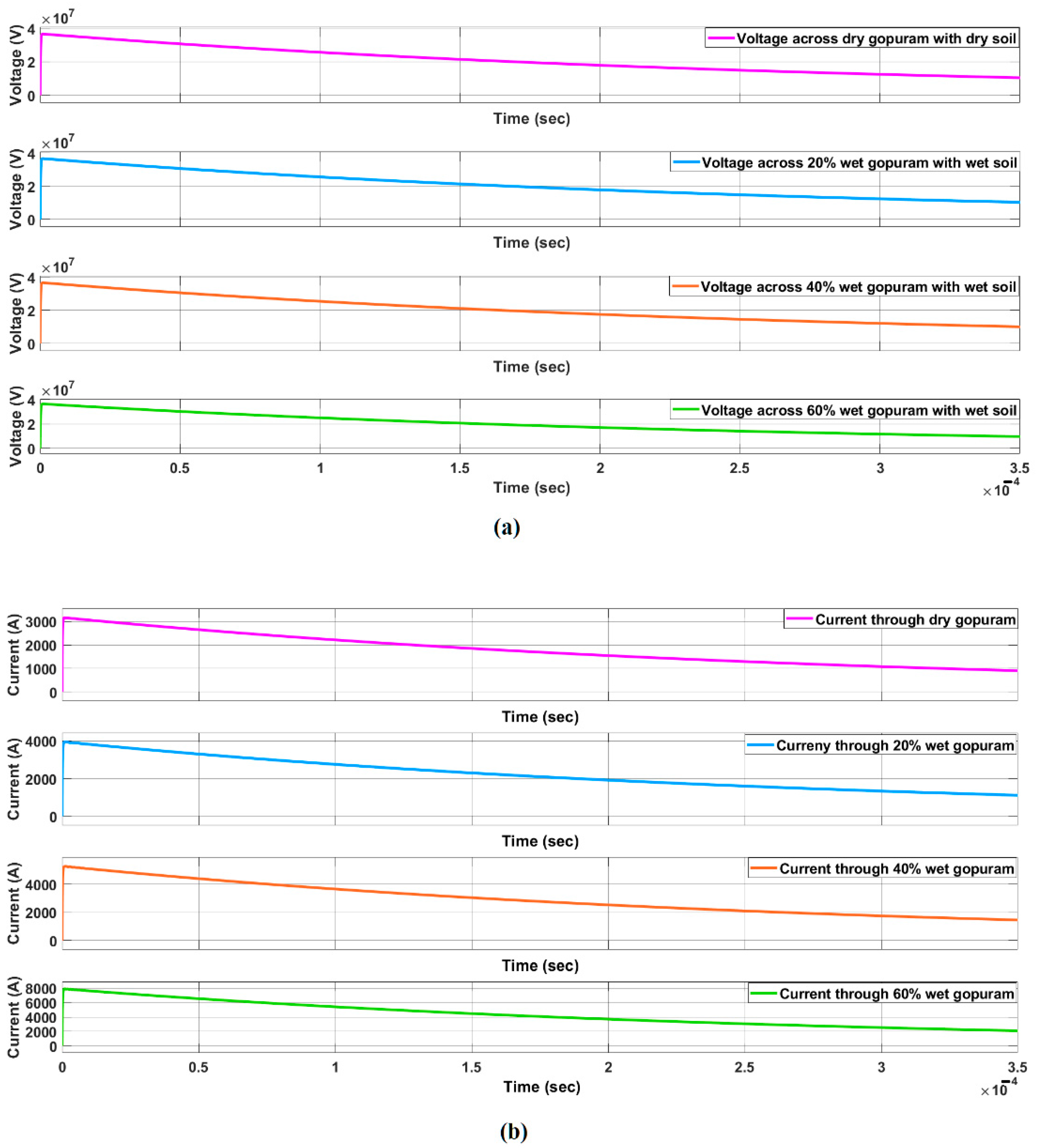
  • It is evident during studies that as the wetness levels increase the impedance (hence the resistance and reactance) of the structural and earthing equivalent models also consequently undergoes changes. The magnitudes of peak current observed through the gopuram and earthing system increase with increasing wetness. This aspect of increasing wetness attribute to the lowering in the value of resistance and impedance whereby leading to larger currents through the structure earthing equivalent model.
  • From the context of varying waveshapes, it is also evinced that increased current through the structure and earthing system during higher levels of wetting is attributed to time (hence, frequency) of the impulse waveshape. With waveshapes of lesser time period, as the frequency is obviously higher, the total impedance of the structure and earthing system is reduced, thereby leading to higher currents through it.
  • It is also observed that there was a minor increase in the ground current in the case of double layer soil resistivity model as compared to its single layer counterpart. Since the double layer model inherently utilizes R-L-C parameters of the soil modelled as two parallel layers, its equivalent resistance value is observed to be lower. It is hence evident that a more conservative strategy for earthing modelling and system is to utilize the double layer model approach. However, it is important that the parameters related to the site condition (soil type, inhomogeneity, resistivity, etc.) are accurately made available before undertaking the modelling and analysis task, as incorrect estimates of such parameters may lead to substantial human hazards.

4.4. Analysis of Impact of Lightning strike on Structure for Human

4.4.1. Touch Potential

From the context of lightning strikes on human, two major aspects related to the impact of such strikes become significant viz., step and touch potential. This aspect becomes most appropriate from the perspective of heritage monuments since several pilgrims and devotees visiting the structure may be prone to lightning as the visitors tend to relax and enjoy the scenic grandeur beauty in the vicinity of the structure. Hence, this analysis aims at ascertaining the touch and step potential during lightning on the proposed structure for varying impulse current wave shapes. A generic layout of the simulation circuit is shown in Figure 23, wherein the human is assumed to be 1.8 m tall and is touching the structure.
Simulations are performed based on variations in impulse current waveshapes, due to varying wetness of the gopuram and human body touch model as stipulated in IEC 62305 to analyse the impact on human, while in touch with the gopuram during the instance of lightning strike at the tip of the gopuram. This study helps in the estimation of touch potential of the human body.
To analyse the impact of lightning-structure-human interaction, initially, simulations are performed by assuming that the structure is not earthed. This study would aid in understanding the need for efficient earthing for the protection of not only the heritage structure but also human safety. Table 7 provides detailed results of voltage and current through the human body when earthing is not provided for the gopuram.
However, after including the earthing system in the simulation studies of lightning-structure-human interaction, the current through human body is significantly reduced. Table 8, Table 9 and Table 10 summarizes the simulation results of the case study for various current impulse wave shapes with varying wetness.
Based on the detailed studies and observations indicated in Table 8, Table 9 and Table 10 the following unique aspects are summarized:
  • From the standpoint/viewpoint of heating effect and energy dissipation considerations on human during lightning, it is evident that due to effective earthing arrangement, the energy is of the order of 80 J to 2 kJ for human equivalent model at 60% wetness. It is found to have had a maximum impact for single layer soil model as compared to its double layer counterpart. Table 11 compares the role of waveshape on its energy capability during lightning-human interaction.
  • It is also evident from this analysis that the impact of lightning on human becomes extremely insignificant only as long as an effective earthing system based on exhaustive analysis of single-layer and double-layer soil models is carried out. Subsequently, the low magnitudes of energy dissipated clearly indicate the role played by an effective earthing system in ensuring safety of human in such heritage installations.
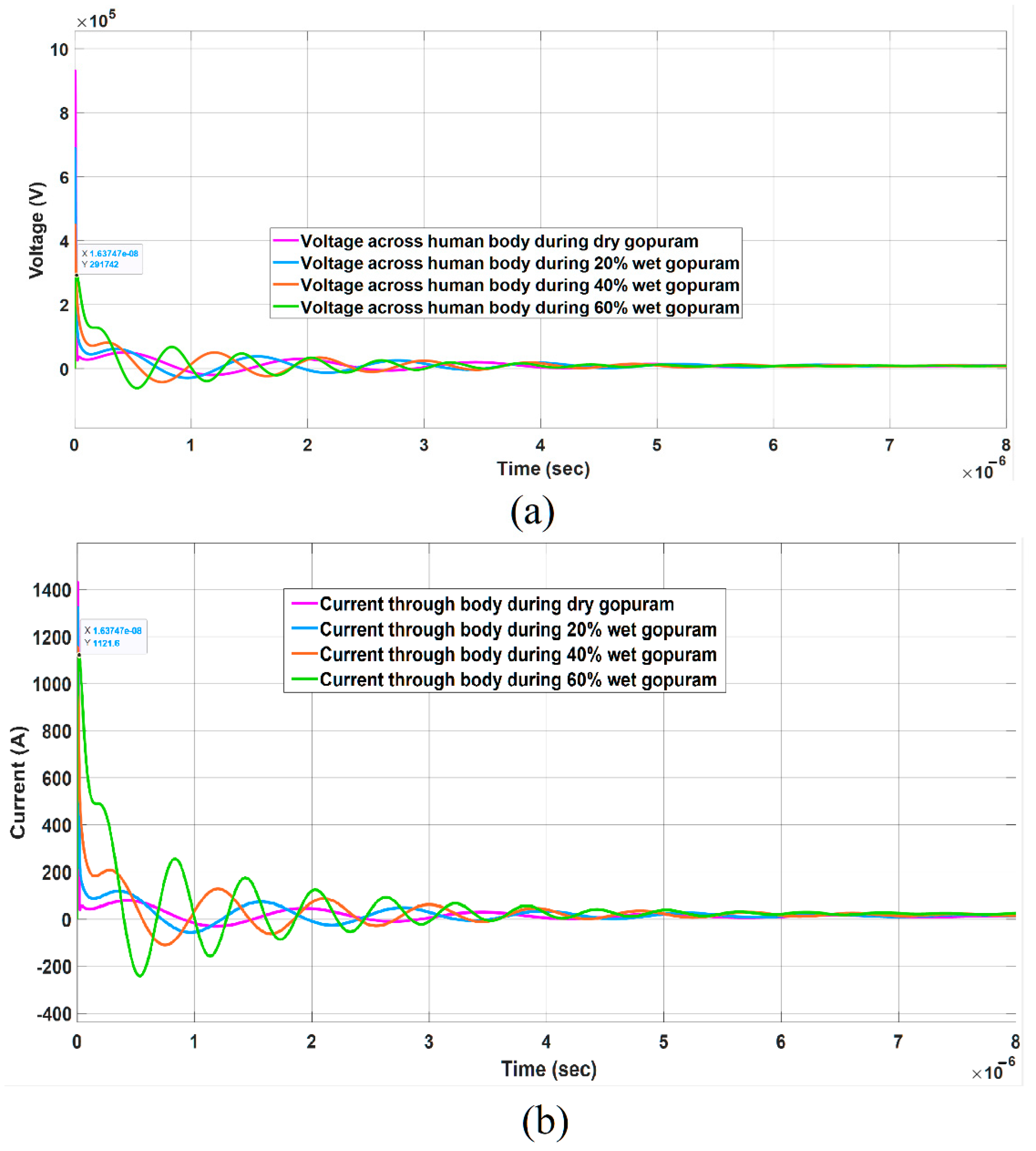
  • It is also specifically observed in R-L-C earthing system models during lightning-human interaction that underdamped oscillations of voltage and current responses occur. Figure 24a,b depicts typical responses that exhibit such underdamped oscillations for a lightning current waveshape of 10/350 µs.
  • It is inferred that sustained oscillations occurring in the range of 500 kHz to 1000 MHz for about a few microseconds may lead to dielectric power losses in the human body. Since human body comprises fluids which could undergo polarization due to dipole moments, such spinning of dipoles at higher frequencies may cause internal injuries to tissues and culminate into muscular contractions and deformities. Similar such studies [29] have been carried out by researchers for ascertaining power loss and breakdown voltage in fluids (air and oil). Such studies in liquid (oil) indicate frequencies in the range of 10 kHz to 100 kHz with high dielectric loss. These similarities clearly establish the role of higher order frequencies in breaking the covalent bonds in liquid dielectrics leading to higher heating and increased dielectric power loss. Through simulation studies which validate this aspect, it would be essential to establish this claim; it is evident from the results indicated in Figure 24a,b that the high-frequency response of current through human would certainly be a cause of concern and endanger human safety.

4.4.2. Step Potential

Another important aspect of lightning-human interaction is the potential rise in the vicinity of direct strike on a nearby object. In this context, simulation studies have been performed to ascertain the level of risk to human in the vicinity of the heritage structure. Figure 25 [26] depicts the electrical equivalent lumped R-C circuit model of human body implemented for estimating the step potential using MATLAB Simulink for varying distance of 1 m, 5 m and 10 m. An equivalent voltage source V e q is applied to estimate the step voltage and current through the human body and the results of step voltage and current through human body are depicted in Figure 26a,b respectively. V e q is given by
V e q = ( ρ I 2 π ) ( 1 r 1 1 r 2 ) .
It is evident that, as the distance between the structure and human increases, the potential decreases drastically across the feet. Since the current through human body is substantially less for a time in the range of a few microseconds, it does not cause any detrimental effects on the human body. Incidentally, if the human is at the range of 1 m, there is a substantial amount of potential across legs, whereby current through human body being large may become dangerous, causing fatal accidents. Based on the simulation results, Table 12 provides the details of step voltage and current at varying distance.

4.5. Analysis of Overall Lightning-Structure-Human Interaction

A Comprehensive analysis of overall framework related to the structure-human safety interaction clearly establishes a few striking observations which include the following:
  • Based on the existing LPS design implemented in the heritage structure taken up for detailed studies in this research, it is evident from Figure 17a that the shielding effectiveness during lightning strike with current strokes of magnitudes of even 100 kA is insufficient. Hence, it is obvious that structure and human are potentially endangered due to incorrect and ineffective LPS leading to severe hazards. However, during the analysis, as indicated in Figure 17b, due to additional lightning rods proposed to be implemented on the corners of parapet wall of the main vimana, a more robust, reliable, and effective shielding is ensured. Table 13 establishes the effectiveness of the modified and enhanced LPS zone of protection whereby ensuring the overall safety to structure and human. The analysis indicates that total expected number of failures per year is estimated to be 3.713 × 10⁻³, which is 269.3 years between consecutive failures
  • From the context of structural safety aspect, it is obvious that effective earthing system is mandatory to prevent large damages to heritage properties. This is even more important when tall structures have relatively sharp edges and corners (inevitable in heritage monuments due to decorative sculptures) which clearly establish the need for suitable earthing system.
  • The effectiveness of earthing and earthing system in addition to soil resistivity models plays a significant role in ensuring human safety aspect. Observations summarized in Table 12 clearly establishes this fact since magnitudes of current of order of 3 kA to 8 kA are likely to flow into the human body (touch potential) when earthing of the heritage structure is not effective.
  • Another major concern related to human safety relates to several devotees and tourists who tend to congregate and rest in the close vicinity of such a large structure, thereby getting exposed to higher step voltages than the tolerable threshold limits. Such dangers could become more rampant when makeshift shelters are close to such heritage structures. This aspect is reiterated and justified in Table 13.

5. Conclusions

Detailed analysis during the course of the research case-studies has provided the authors with a few major recommendations as a generic outcome for the proposed framework for lightning-structure-human interaction modelling. The results of the analysis are summarized and serve as possible recommendations:
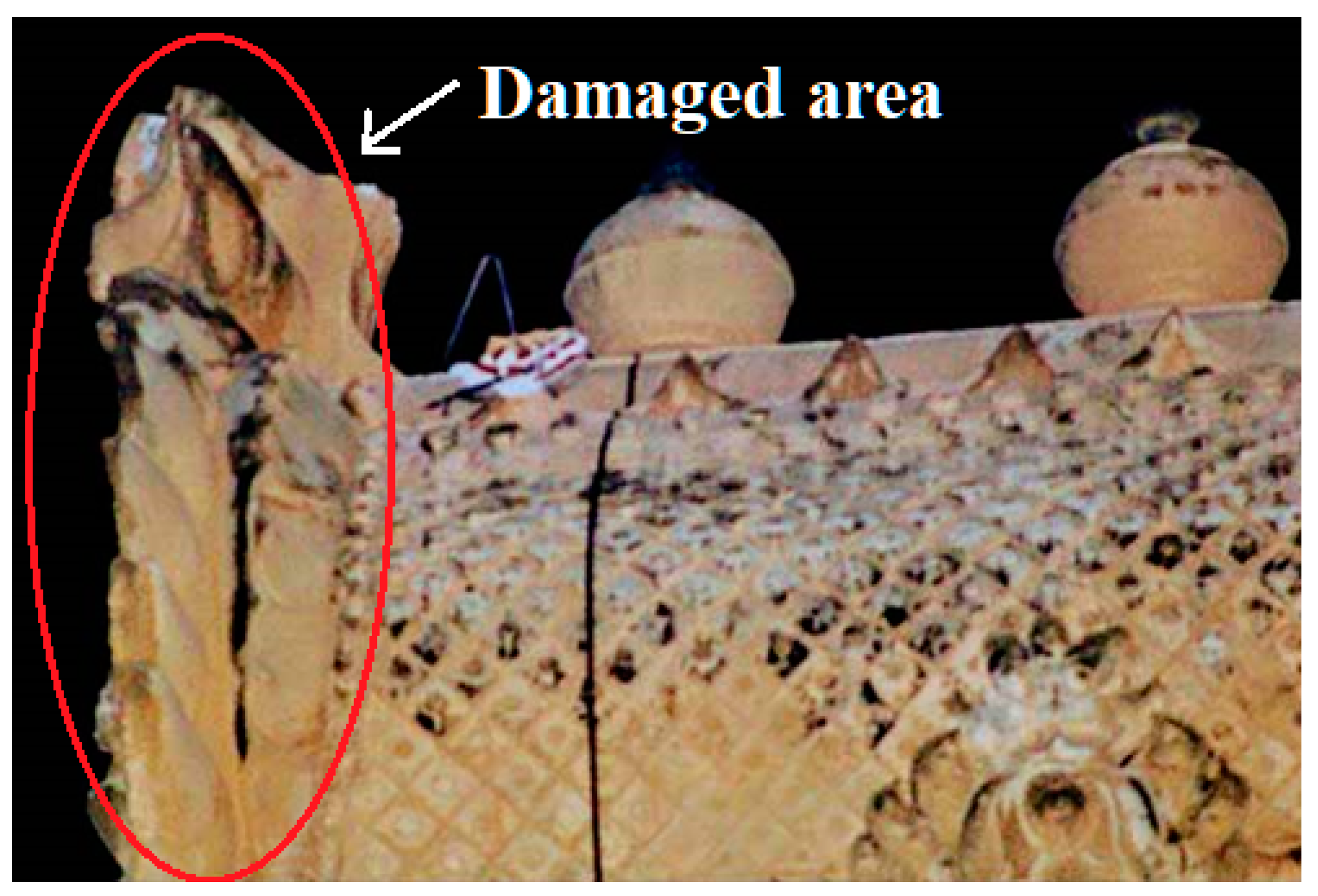
  • It is significant to note that the entire modelling is based on the premise that accurate values of structural properties of the heritage monument such as permittivity (dielectric constant) of rock, mortars, etc., conductivity (resistivity) of structure and soil, precise dimensions of the monument etc., are prerequisites for reliable and effective analysis and implementation. Hence, correlation of the role of skin depth of the structure would be a challenging proportion. In this study a relatively correlatable measure on the extent of damage is made evident. This aspect requires more thorough and detailed studies with more case studies of similar damages in other heritage structures so as to ascertain and validate this claim.
  • It is important as a first yet vital step to ensure that a highly effective shielding zone during LPS implementation based on IEC 62305 is implemented. This, in fact, would virtually obviate the need for additional protective measures at a later point during maintenance and upkeep of the heritage facility.
  • It is also evident from the detailed studies and analysis that the double layer soil model is more appropriate to ascertain the extent of ground currents during a lightning strike as it clearly indicates a safer path for earthing large currents during such strikes. However, practically, this model would be appropriate in locations which exhibit a heterogeneity as indicated in soil texture of specific locations and hence becomes relevant only in specific cases. From the viewpoint of a more onerous condition, it is practical to assume a larger resistance (impedance) during lightning, as this would ensure that higher risk is evaluated. Also, ensuring exceptionally low grounding resistance becomes a complex task due to space and ergonomic constraints in an existing heritage structure. It is pertinent to note that modification in the vicinity of age-old structures is invariably prohibited by governmental and archaeological agencies since such structure may include rare artifacts, idols, sculptures, other treasure, etc.
  • From the perspective of human safety wherein it is particularly important to ensure that the values of both step and touch potentials are to be within tolerable limits, this study clearly emphasizes the need for safe distance (at least 10 m away from the structure) to be maintained by the tourists and devotees visiting such heritage structure to clearly obviate the danger and risk of ground potential rise during lightning strikes. It is suggested that humans are given a separate shelter or resting place away from such tall structures to prevent mishaps during such strikes. It would also be more appropriate to implement an alarm annunciator system, so that the tourists are moved away from the access of such structures which are prone to lightning risk.

Author Contributions

Implementation, Investigation, simulation, S.S.; Analysis, Supervision, Proofreading, V.I. All authors have read and agreed to the published version of the manuscript.

Funding

This research received no external funding.

Data Availability Statement

Not applicable.

Acknowledgments

The authors of this research are grateful to S. Venkatesh for the guidance provided to work for project sanctioned by the Department of Science & Technology (DST)—Government of India—The Bilateral India-Sri Lanka Research Project Grant No.: DST/INT/SL/P-14/2016/C&G which forms a part of this research study. The authors of this research work are also extremely grateful to the Archaeological Survey of India (ASI), New Delhi for according permission & approval and for their continued support to undertake lightning protection studies.

Conflicts of Interest

The authors declare no conflict of interest.

References

  1. Cooray, V. An Introduction to Lightning; Springer: Dordrecht, The Netherlands, 2015. [Google Scholar]
  2. Wetter, M.; Kern, A. Number of lightning strikes to tall structures—Comparison of calculations and measurements using a modern lightning monitoring system. In Proceedings of the 2014 International Conference on Lightning Protection (ICLP), Shanghai, China, 11–18 October 2014. [Google Scholar]
  3. Accidental Deaths & Suicides in India; National Crime Records Bureau, Ministry Home Affairs, Government India: Mahipalpur, India, 2015.
  4. Singh, O.; Singh, J. Lightning fatalities over India: 1979–2011. Meteorol. Appl. 2015, 22, 770–778. [Google Scholar] [CrossRef]
  5. Ioannidis, A.I.; Mikropoulos, P.N.; Tsovilis, T.E.; Kokkinos, N.D. A Fractal-Based Approach to Lightning Protection of Historical Buildings and Monuments: The Parthenon Case Study. IEEE Ind. Appl. Mag. 2022, 28, 20–28. [Google Scholar] [CrossRef]
  6. Tsintskaladze, G.; Sharashenidze, T.; Gabunia, V.; Beridze, G. Actions of factors caused by lightning on historical and cultural monuments and the possibilities of their prevention on the example of Abuli fortress. Int. J. Latest Eng. Manag. Res. (IJLEMR) 2019, 4, 92–97. [Google Scholar]
  7. Fisher, C.E. Lightning Protection for Historic Structures; 50 Preservation Briefs; Government Printing Office: Washington, DC, USA, 2017; pp. 1–20.
  8. Sreedhar, S.; Venkatesh, S. Lightning strokes and its effects on histor- ical monuments, heritage properties and important landmarks a detailed perspective of traditional and scientific methods of lightning protection systems. Int. J. Eng. Technol. 2018, 7, 784–794. [Google Scholar] [CrossRef]
  9. Lightning Arrester Averts Major Damage to Big Temple Gopuram, DTNEXT. 6 June 2018. Available online: https://www.dtnext.in/News/TamilNadu/2018/06/06020148/1075055/Lightning-arrester-averts-major-damage-to-Big-Temple-.vpf (accessed on 20 February 2021).
  10. Srinivasan, V.; Fernando, M.; Kumara, S.; Selvaraj, T.; Cooray, V. Modeling and assessment of lightning hazards to humans in heritage monuments in India and Sri Lanka. IEEE Access 2020, 8, 228032–228048. [Google Scholar] [CrossRef]
  11. Venkatesh, S.; Thirumalini, S.; Chandrasekaran, S.; Sreedhar, S.; Kakria, K.; Fernando, R.; Kumara, J.R.S.S. Three-dimensional implementation of modified rolling sphere method for lightning protection of giant medieval Chola monument in South India. In Proceedings of the 14th Conference on Industrial and Information Systems (ICIIS), Kandy, Sri Lanka, 18–20 December 2019; pp. 535–540. [Google Scholar]
  12. IEC 62305; Part 1 to 4. Protection Against Lightning. International Electrotechnical Commission: London, UK, 2006.
  13. Cooray, G. Vernon. In The Lightning Flash; No. 34; IET: London, UK, 2003. [Google Scholar]
  14. Mithra, J.; Baskaran, R. Soil classification and land capability of Thanjavur taluk, Thanjavur district, Tamilnadu–India. Int. J. Curr. Res. 2016, 8, 40161–40164. [Google Scholar]
  15. IEEE 998; IEEE Guide for Direct Lightning Stroke Sheilding of Substations. IEEE: Piscataway, NJ, USA, 2012.
  16. Horvath, T. Understanding Lightning and Lightning Protection: A Multimedia Teaching Guide; Wiley: Hoboken, NJ, USA, 2006. [Google Scholar]
  17. Mariscotti, A. Self and mutual capacitance of conductors in air and lossy earth with application to electrified railways. Arch. Electr. Eng. 2019, 68, 859–873. [Google Scholar]
  18. Gomes, C.; Kadir, M.Z.A.A.; Izadi, M.; Gomes, A. Lightning current and voltage distribution of large axially symmetric buddhist stupa in Sri Lanka. In Proceedings of the 2014 International Conference on Lightning Protection (ICLP), Shanghai, China, 11–18 October 2014; pp. 1637–1651. [Google Scholar]
  19. Cooray, V. Lightning Electromagnetics; Institution of Engineering and Technology: London, UK, 2012. [Google Scholar]
  20. Cooray, V. Lightning Protection; The Institution of Engineering and Technology: London, UK, 2009. [Google Scholar]
  21. Mohamad, N.N.; Abdullah, S. Comparison between utility sub-station and imitative earthing systems when subjected under lightning response. Int. J. Electr. Power Energy Syst. 2012, 43, 156–161. [Google Scholar] [CrossRef]
  22. IEEE Std 80-2013 (Revision of IEEE Std 80-2000/Incorporates IEEE Std 80-2013/Cor 1-2015); IEEE Guide for Safety in AC Substation Grounding. IEEE: Piscataway, NJ, USA, 2015; pp. 1–226. [CrossRef]
  23. Wadhwa, C.L. High Voltage Engineering; New Age International: New Deli, India, 2006. [Google Scholar]
  24. Tomoaki, N.; Watanabe, S. Postured voxel-based human models for electromagnetic dosimetry. Phys. Med. Biol. 2008, 53, 7047–7061. [Google Scholar]
  25. King, R.W.P. A review of analytically determined electric fields and currents induced in the human body when exposed to 50-60-Hz electromagnetic fields. IEEE Trans. Antennas Propag. 2004, 52, 1186–1192. [Google Scholar] [CrossRef]
  26. Kantartzis, N.V.; Amanatiadis, S.A.; Alrim, V.A.; Christos, S. Antonopoulos. Accurate electromagnetic field exposure characterization due to mediated lightning strikes via an efficient finite-difference time-domain based human body model. IET Sci. Meas. Technol. 2016, 10, 124–129. [Google Scholar]
  27. IEC 60060; Part 3, Definitions and Requirements for On-Site Testing. International Electrotechnical Commission: London, UK, 2006.
  28. Selvaraj, T.; Srinivasan, V.; Raneri, S.; Fernando, M.; Kakria, K.; Jayasingh, S. Response of Organic Lime Mortars to Thermal and Electrical Shocks Due to Lightning Strikes. Sustainability 2020, 12, 7181. [Google Scholar] [CrossRef]
  29. Saravanan, S.; Rajesh, R.; Karthikeyan, B.; Venkatesh, S. Dielectric Integrity Test- A Tuned Circuit Approach. In Proceedings of the 2006 IEEE 8th International Conference on Properties & applications of Dielectric Materials, Bali, India, 26–30 June 2006; pp. 380–383. [Google Scholar] [CrossRef]
Figure 1. Generic framework proposed for modelling lightning-structure-human interaction studies.
Energies 15 07053 g001
Figure 2. 3D layout of Brihadisvara Temple.
Energies 15 07053 g002
Figure 3. Modelling of RSM with Level-IV LPS for heritage monument.
Energies 15 07053 g003
Figure 4. 3D plot of main Vimana.
Energies 15 07053 g004
Figure 5. Electrical field plot of the structure.
Energies 15 07053 g005
Figure 6. Voltage profile of the gopuram with respect to height.
Energies 15 07053 g006
Figure 7. Generic equivalent electrical circuit model of main Vimana.
Energies 15 07053 g007
Figure 8. Generic representation of skin depth in a conductor.
Energies 15 07053 g008
Figure 9. Generic layout of lightning on main Vimana.
Energies 15 07053 g009
Figure 10. (a) 2D layout of main vimana with FEM, (b) Depth of penetration at 500 kHz.
Energies 15 07053 g010
Figure 11. Generic earthing equivalent model (a) for low frequency (b) for high frequency.
Energies 15 07053 g011
Figure 12. Generic circuit of multi-stage Marx impulse generator.
Energies 15 07053 g012
Figure 13. Generic circuit of multi-stage Marx impulse generator.
Energies 15 07053 g013
Figure 14. Output voltage waveshapes of impulse generator.
Energies 15 07053 g014
Figure 15. Generic representation of step and touch potential.
Energies 15 07053 g015
Figure 16. Electrical equivalent circuit of human body.
Energies 15 07053 g016
Figure 17. (a) LPZ based on RSM Implementation for currently installed LPS using SES Shield-3D, (b) LPZ based on RSM Implementation with additional LPS using SES Shield-3D.
Energies 15 07053 g017
Figure 18. Half contour layout for depth of penetration in main vimana at 500 kHz.
Energies 15 07053 g018
Figure 19. Keralanthakan gopuram damaged due to lightning strike.
Energies 15 07053 g019
Figure 20. Depth of penetration at (a) 5 kHz, (b) 10 kHz, (c) 100 kHz and (d) 500 kHz.
Energies 15 07053 g020aEnergies 15 07053 g020b
Figure 21. Simulation circuit for lightning-structure interaction.
Energies 15 07053 g021
Figure 22. (a) Voltage across gopuram at varying wetness and (b) Current through gopuram at varying wetness for 10/350 µs impulse waveshape.
Energies 15 07053 g022
Figure 23. Simulation circuit diagram of Lightning-Structure-Human interaction.
Energies 15 07053 g023
Figure 24. (a) Voltage across human body with varying wetness and (b) Current through human body with varying wetness.
Energies 15 07053 g024
Figure 25. Simulation circuit of human body for step potential.
Energies 15 07053 g025
Figure 26. (a) Step voltage of human body at various distances from gopuram and (b) Current through human body at various distances from gopuram.
Energies 15 07053 g026
Table 1. R, L and C values of slabs of Vimana.
S. No.Length
(mm)
Width
(mm)
Height
(mm)
Overall Height (mm)Inductance (µH)Resistance
(Ω)
Capacitance(F)
125,00025,00014,50014,5004.26701959223.21.91 × 10−9
223,00023,000500019,5003.5533638379.45184.68 × 10−9
321,00021,000300022,5003.1746629496.80246.51 × 10−9
419,00019,000300025,5002.8852214688.31025.33 × 10−9
518,00018,000300028,5002.7404985049.25934.78 × 10−9
617,00017,000300031,5002.595773810.3814.26 × 10−9
715,50015,500300034,5002.37868294112.4873.55 × 10−9
813,00013,000300037,5002.01685195117.7512.49 × 10−9
911,00011,000300040,5001.7273712424.791.79 × 10−9
1010,00010,000300043,5001.582623613301.48 × 10−9
1190009000300046,5001.43786971937.0371.20 × 10−9
1280008000300049,5001.2931080546.8759.44 × 10−10
1370007000300052,5001.14833655461.2247.23 × 10−10
1460006000250055,0000.98127602369.4446.38 × 10−10
1550005000200057,0000.814215763805.53 × 10−10
Table 2. Resistance and Capacitance values of impulse generator for various waveshapes.
Impulse WaveshapesValues of Wave Shaping Components
R1 (Ω)R2 (Ω)C1 (F)C2 (F)
0.25/100 µs513000.1 × 10−69 × 10−9
1/200 µs5.53000.9 × 10−625 × 10−9
10/350 µs1006500.6 × 10−623 × 10−6
Table 3. Frequency versus depth of penetration.
S. No.FrequencyDepth of Penetration ( δ )
15 kHz<1 m
250 kHz0.8 m to 1 m
3100 kHz0.7 m
4500 kHz0.5 m
51000 kHz0.3 m
Table 4. Summary of voltage drop and Current through gopuram with varying wetness for Impulse wave shape of 10/350 µs.
10/350 µs
Single Layer Model
V P e a k   ( Dry )   MV I P e a k   ( Dry )   Amps V P e a k
(20% Wet) MV
I P e a k  
(20% Wet) Amps
V P e a k  
(40% Wet) MV
I P e a k  
(40% Wet) Amps
V P e a k  
(60% Wet) MV
I P e a k  
(60% Wet) Amps
Resistive
Earthing
36.5483144.3136.5433942.4636.5345261.8736.5177913.19
Lumped RC Earthing36.5483158.1136.5433945.8436.5465267.8936.5177926.81
Lumped RLC earthing36.5473158.0336.5433945.8436.5345267.8636.5177926.88
Double layer model
Resistive
Earthing
36.5483145.936.5433942.9136.5345262.6936.5177914.86
Lumped RC Earthing36.5483158.0836.5473946.3736.5345267.9336.5177926.73
Lumped RLC earthing36.5473158.0136.5433945.8436.5345267.9136.5177926.8
Table 5. Summary of voltage drop and Current through gopuram with varying wetness for Impulse wave shape of 1/200 µs.
1/200 µs
Single Layer Model
V P e a k   ( Dry )   MV I P e a k   ( Dry )   Amps V P e a k
(20% Wet) MV
I P e a k  
(20% Wet) Amps
V P e a k  
(40% Wet) MV
I P e a k  
(40% Wet) Amps
V P e a k  
(60% Wet) MV
I P e a k  
(60% Wet) Amps
Resistive
Earthing
36.5783152.7836.5753922.936.5685217.1436.5567885.75
Lumped RC Earthing36.5783167.6236.5753928.6136.5685228.1236.5557920.25
Lumped RLC earthing36.5763168.1336.5753929.7236.5685228.9136.5557924.56
Double layer model
Resistive
Earthing
36.573154.0736.5663922.5936.5605218.3336.5477896.77
Lumped RC Earthing36.573168.2336.5663929.536.565229.4936.5477928.59
Lumped RLC earthing36.5693168.7236.5663930.336.565229.7236.5477929.73
Table 6. Summary of voltage drop and Current through gopuram with varying wetness for Impulse wave shape of 0.25/100 µs.
0.25/100 µs
Single Layer Model
V P e a k   ( Dry )   MV I P e a k   ( Dry )   Amps V P e a k
(20% Wet) MV
I P e a k  
(20% Wet) Amps
V P e a k  
(40% Wet) MV
I P e a k  
(40% Wet) Amps
V P e a k  
(60% Wet) MV
I P e a k  
(60% Wet) Amps
Resistive Earthing36.5523147.4836.4043931.1936.1635206.8536.6927703.63
Lumped RC Earthing36.5513161.0936.4033934.4936.1625212.6536.697716.35
Lumped RLC earthing36.5513161.0136.4033934.4936.1625212.6536.697716.34
Double layer model
Resistive Earthing36.5523149.1636.4043931.7236.1645207.5536.6927705.16
Lumped RC Earthing36.553161.1836.4043934.636.1635212.636.697716.23
Lumped RLC earthing36.553161.136.4043934.636.1625212.4736.697716.23
Table 7. Voltage and Current through human body when the structure is not earthed.
Impulse Wave ShapeDry20% Wetness40% Wetness60% Wetness
V P e a k I P e a k V P e a k I P e a k V P e a k I P e a k V P e a k I P e a k
10/350 µs2,744,9302990.163,438,4103717.914,432,7504916.715,112,8907239.15
1/200 µs2,026,1202988.892,445,3503725.763,220,5404994.444,678,5907501.02
0.25/100 µs1,992,2503052.511,997,0203825.482,396,9805107.963,455,1307624.1
Table 8. Summary of simulation results of Lightning-structure-human interaction: voltages drop and Current through gopuram and human body with varying wetness for Impulse wave shape of 10/350 µs.
10/350 µs
Single Layer Soil
V P e a k   ( Dry )   MV I P e a k   ( Dry )   Amps V H u m a n   ( Dry )   V I H u m a n   ( Dry )   Amps V P e a k   ( 20 %   Wet )   MV I P e a k   ( 20 %   Wet )   Amps V H u m a n   ( 20 %   Wet )   V I H u m a n   ( 20 %   Wet )   Amps V P e a k   ( 40 %   Wet )   MV I P e a k   ( 40 %   Wet )   Amps V H u m a n   ( 40 %   Wet )   V I H u m a n   ( 40 %   Wet )   Amps V P e a k   ( 60 %   Wet )   MV I P e a k   ( 60 %   Wet )   Amps V H u m a n   ( 60 %   Wet )   V I H u m a n   ( 60 %   Wet )   Amps
Resistive Earthing36.6482859.881193,456297.11936.6443757.9689,201.4171.2436.6384941.128113,161289.47236.6247333.412153672588.728
Lumped RC Earthing36.6473093.99649,711.275.26436.6443817.46553,505.9114.84536.6385043.92675,079.5192.09436.6247548.506100,644385.834
Lumped RLC earthing36.6471737.44930,6651431.7736.6442608.32688,3541323.7336.6384081.69449,7221153.136.6246806.77291,7451121.61
Double layer Soil
Resistive Earthing36.6482888.302177,716272.91836.6443772.04885,466.5164.07236.6384968.153108,319277.09736.6247382.828147,028563.382
Lumped RC Earthing36.6473108.70749,726.676.41336.6443853.67959,812.8114.85136.6385120.34475,175.4192.36636.6247647.624100,599385.706
Lumped RLC earthing36.6471754.78930,8251430.2636.6442644.53688,3421323.7136.6384160.73449,7391150.7636.6246906.69291,7501121.63
Table 9. Summary of simulation results of Lightning-structure-human interaction: voltages drop and Current through gopuram and human body with varying wetness for Impulse wave shape of 1/200 µs.
1/200 µs
Single Layer Soil
V P e a k   ( Dry )   MV I P e a k   ( Dry )   Amps V H u m a n   ( Dry )   V I H u m a n   ( Dry )   Amps V P e a k   ( 20 %   Wet )   MV I P e a k   ( 20 %   Wet )   Amps V H u m a n   ( 20 %   Wet )   V I H u m a n   ( 20 %   Wet )   Amps V P e a k   ( 40 %   Wet )   MV I P e a k   ( 40 %   Wet )   Amps V H u m a n   ( 40 %   Wet )   V I H u m a n   ( 40 %   Wet )   Amps V P e a k   ( 60 %   Wet )   MV I P e a k   ( 60 %   Wet )   Amps V H u m a n   ( 60 %   Wet )   V I H u m a n   ( 60 %   Wet )   Amps
Resistive Earthing36.5482861.34184,944283.9536.5433786.71280,959.4155.41836.5345009.2598,764252.5536.5177433.499125,399480.211
Lumped RC Earthing36.5483088.5545,332.769.65036.5433844.24452,913.4101.28636.5345135.10763,233.1132.54336.5177624.91878,800301.922
Lumped RLC earthing36.5472441.102466,319716.93836.5433285.705343,895659.83536.5344693.713224072574.52736.5177299.891162,760625.099
Double layer Soil
Resistive Earthing36.5482872.339169,570360.37136.5433794.03677,387.8148.53436.5345021.39494,284.5241.13636.5177458.516119,533456.864
Lumped RC Earthing36.5483088.53345,342.869.66736.5433844.91952,924.7101.61136.5345136.11863,531.9162.52236.5177624.16578,987.8302.695
Lumped RLC earthing36.5472433.061467,440719.12936.5433285.581343,705660.95936.5344693.653223,890625.57736.5177350.316162,660574.694
Table 10. Summary of simulation results of Lightning-structure-human interaction: voltages drop and Current through gopuram and human body with varying wetness for Impulse wave shape of 0.25/100 µs.
0.25/100 µs
Single Layer Soil
V P e a k   ( Dry )   MV I P e a k   ( Dry )   Amps V H u m a n   ( Dry )   V I H u m a n   ( Dry )   Amps V P e a k   ( 20 %   Wet )   MV I P e a k   ( 20 %   wet )   Amps V H u m a n   ( 20 %   Wet )   V I H u m a n   ( 20 %   Wet )   Amps V P e a k   ( 40 %   Wet )   MV I P e a k   ( 40 %   Wet )   Amps V H u m a n   ( 40 %   Wet )   V I H u m a n   ( 40 %   Wet )   Amps V P e a k   ( 60 %   Wet )   MV I P e a k   ( 60 %   Wet )   Amps V H u m a n   ( 60 %   Wet )   V I H u m a n   ( 60 %   Wet )   Amps
Resistive Earthing36.5512915.325156,722233.16536.4043858.397839,568.772.812236.1635089.91649,213.3117.09436.6927478.03468,165.7226.066
Lumped RC Earthing36.5493142.50312,085.118.55736.4033911.22812,10423.22236.1625181.747412,09330.912636.697670.598611,966.345.8214
Lumped RLC earthing36.5483107.89834,477.453.07236.4033885.695325,335.448.754736.1625170.38120,330.4242.28936.697619.75116,489.996.669
Double layer Soil
Resistive Earthing36.5512940.867140,490209.01336.4043865.92835,681.565.70236.1635102.82344,108.1104.90736.6927504.15760,676.9201.493
Lumped RC Earthing36.5513142.64912,086.818.56136.4043911.413912,105.123.226136.1635181.673312,089.230.906736.6907670.41911,966.745.811
Lumped RLC earthing36.5513108.03334,513.653.09736.4053886.14125,234.948.30936.1635170.75521,918.151.90536.6907619.58620,329.196.654
Table 11. Energy (J) through human body for varying current waveshapes.
Rhuman at 60% WetnessImpulse WaveshapeSoil ModelEarthing SystemIpeak (A)Ihalf (A)Thalf (Sec)Energy (J)
4000 Ω10/350 µsSingle layer soilR588.728294.364 3.6 × 10 7 124.78
R-L-C1121.61560.805 1.2 × 10 7 150.96
Double
layer soil
R563.382281.691 3.59 × 10 7 113.95
R-L-C1121.63560.815 1.2 × 10 7 150.97
1/200 µsSingle layer soilR480.211240.1055 4.04 × 10 7 93.163
R-L-C625.099312.5495 3.4 × 10 7 132.85
Double
layer soil
R456.864228.432 4.04 × 10 7 84.325
R-L-C574.694287.347 3.4 × 10 7 112.29
0.25/100 µsSingle layer soilR226.066113.033 3.37 × 10 5 1722.3
R-L-C96.66948.3345 1.18 × 10 5 110.27
Double
layer soil
R201.493100.7465 3.34 × 10 5 1356
R-L-C96.65448.327 1.18 × 10 5 110.24
Table 12. Step voltage and current at varying distances.
Distance (m)Step Voltage (V)Current (A)
13352.3522.9260
5218.951.471
1054.6060.367
Table 13. Shielding failure analysis for enhanced LPS calculated according to IEC 62305.
Stroke Current Range (kA)Unprotected Area (m2)Probability of Stroke (%)Expected Number of Failures (Failures/Year)
(5–18)932030.463.12 × 10−3
(18–31)158033.925.90 × 10−4
(31–44)416.827.40 × 10−7
(44–57)07.590.00
(57–70)03.720.00
(70–83)020.00
(83–96)01.170.00
(96–109)00.730.00
(109–122)00.480.00
(122–135)00.330.00
(135–148)00.230.00
(148–161)00.170.00
(161–174)00.130.00
(174–187)00.10.00
(187–200)00.080.00
Publisher’s Note: MDPI stays neutral with regard to jurisdictional claims in published maps and institutional affiliations.

