Article

Three-Phase Grid-Connected Inverter Power Control under Unbalanced Grid Conditions Using a Proportional-Resonant Control Method †

Electrical and Computer Engineering Department, Auburn University, Auburn, AL 36849, USA
*
Author to whom correspondence should be addressed.
This paper is an extended version of our paper published in 47th Annual Conference of the IEEE Industrial Electronics Society (IECON 2021), Toronto, ON, Canada, 13–16 October 2021; pp. 1–6. https://doi.org/10.1109/IECON48115.2021.9589120.
Energies 2022, 15(19), 7051; https://doi.org/10.3390/en15197051
Submission received: 18 August 2022 / Revised: 14 September 2022 / Accepted: 22 September 2022 / Published: 26 September 2022
(This article belongs to the Special Issue Control and Stability of Grid-Connected Power Electronic Converters)

Abstract

:
Proposed in this article is bidirectional real and reactive power control of a three-phase grid-connected inverter under unbalanced grid conditions using a proportional-resonance controller. Different unbalanced grid conditions have been studied, such as unbalanced three-phase load and unbalanced grid impedance. These unbalanced scenarios generate unbalanced grid currents and unbalanced point-of-common-coupling (PCC) voltages, causing large oscillations in both real and reactive power transferred to the grid. The purposes of the suggested technique are to balance the grid currents and point-of-common-coupling voltages as well as control the power injected into the grid. As a result, balanced PCC voltages are guaranteed, the oscillation in real and reactive power is reduced, and power control is achieved. The proposed method’s performance has been verified in MATLAB/SIMULINK simulation software, and different experimental results have been obtained using a real-time interface platform, dSPACE DS1202.

1. Introduction

Renewable energy resources (RES) have an impact on the electrical grid’s operation. The three-phase inverter that is connected to the grid can be used as a power controller. To obtain good performance, the inverter can be connected to different DC sources such as batteries, RES, or combinations of batteries and RES [1,2]. The uncertainty of RES, as well as the imbalances between generation, distribution, and consumption, can cause numerous issues in inverter operations. These problems can be solved by using energy storage systems (ESS) with RES [3]. As a result, ESS can contribute to and maintain load balance by charging or discharging based on the amount of desired and/or available RES power.
A variety of control techniques have been used to control the power and current of grid-connected three-phase inverters, including proportional-integral (PI) and proportional-resonant (PR) control methods [4,5]. These approaches, on the other hand, simply examine balanced grid situations.
When the amplitude and phase of voltages/currents in a three-phase system differ, they are called unbalanced [6]. The three-phase grid system can become unbalanced due to single-phase loads, single-phase renewable energy sources connected to the grid, unbalanced loading, and load changes [7]. This issue has an impact on controller behavior, the inverter circuit’s intrinsic character, and other three-phase loads that may be linked to the grid.
The PI control approach performs poorly under unbalanced grid situations, along with current oscillations. The oscillation problem in the PI-controller has been handled using a variety of control strategies, including the decoupled double synchronous reference frame phase-locked loop (DDSRF PLL) in [8], direct phase-angle detection (DPD-SR) in [9], and optimum control based on DDSRF in [10]. Using two PLLs, the DDSRF method was able to control the grid currents under unbalanced grid conditions. However, this method has been modified and simplified in [11]. So, only one PLL can be used, and power control is achieved as well using a PI-controller in unbalanced grid situations.
Shunt active power filters have been used to improve the harmonic content of the grid current in cases of nonlinear loads. In addition, it has been used to solve three-phase systems under unbalanced situations to balance the grid currents [12]. Using a time-domain symmetrical component extraction approach, the method in [13] demonstrated an easy and efficient solution to balance grid currents in unbalanced conditions. This approach calculates the sequence components without the need for complex transformations by using time delays and basic addition and subtraction.
A time-domain symmetrical component extraction method with a P-controller was used to achieve power control under unbalanced grid situations in [14]. The reference current was obtained from the negative/zero sequence components of the unbalanced load currents as well as the power command current. The control system was simple as only a P-controller was utilized. The P-controller, however, has a steady-state error, which is a disadvantage of this approach. To improve the controller performance, a PR controller was used to eliminate the steady-state error [15].
Several control techniques have been suggested under unbalanced grid voltage conditions [16,17,18,19,20,21,22]. Some approaches extracted the symmetrical components of the unbalanced grid voltages ( positive and negative phase-sequence) and then tried to balance currents under unbalanced grid voltage conditions. In [17], different control parameters that were used to estimate the grid impedance were discussed, while in [18], the system parameters for balancing the system were estimated.
Many methods were used for unbalanced current compensation or reduction as discussed in [23,24,25,26], and different control cases under unbalanced load were discussed in [27,28].
A phase-locked loop (PLL) and a Park transformation are required when using a PI controller. However, the PR controller does not need a Park transformation or a PLL which makes it simpler. In [29], a notch filter was added to improve the PR controller performance. This control scheme can be utilized to reduce the inverter’s negative-sequence impedance and decrease the voltage drop. An enhanced proportional-resonant controller (EPR) was developed in [30]. To reduce grid current harmonics induced by a distorted grid, a current controller for a grid-connected solar system was utilized. Under unbalanced grid situations, a modified PR control strategy (MPRS) for controlling the power of grid-connected three-phase inverters was presented in [31]. The premise behind this method is that the system is operating with an unbalanced load and an unbalanced grid current. Two signals have been used to regulate the inverter’s reference current: the load current and the inverter current. By avoiding the need for a phase-locked loop, the PR-controller decreases the complexity.
Many approaches to bidirectional power flow are discussed in the literature, but they all worked under balanced grid conditions. In addition, several methods to balance the grid under unbalanced grid conditions without achieving power control have also been described. However, very few researchers discuss achieving both targets (balancing the grid and applying power control). Also, bidirectional power control under unbalanced grid conditions is not discussed.
In the MPRS method, the PR-controller was shown to be effective in unbalanced grid situations. However, this method was applied by neglecting the grid impedance, balanced grid, and PCC voltages. This means the unbalanced scenario was only considered under unbalanced grid currents without considering unbalanced PCC voltages. Furthermore, the power control of a three-phase system under an unbalanced load (unbalanced grid currents) has been achieved in only one direction. The main contribution of this article is to improve and expand the PR-controller approach described in the MPRS method to get bidirectional power control of the grid-connected inverter in various unbalanced grid situations. So, the proposed technique can simultaneously fulfill these goals: balancing grid currents and point-of-common-coupling voltages and bidirectional power control. MATLAB/SIMULINK studies along with hardware experimental results validate the proposed control method.
The literature discusses balancing the three-phase grid under unbalanced grid conditions and discusses a method of controlling the power and balancing the grid, but that approach was only used under strong grid situations (where the grid impedance was neglected). In addition, power control for an unbalanced load (unbalanced grid currents) has been accomplished in only one direction. But this effort extends the previous research to cover unbalanced grid impedance, unbalanced PCC, and unbalanced grid current situations as well as bidirectional power control.
The novel contributions of this work are as follows:
  • Presenting a method of bidirectional power control of real and reactive power under different unbalanced scenarios.
  • Balancing the grid currents and PCC voltages.
  • Real and reactive power fluctuations under unbalanced grid situations have been minimized.
  • If the unbalanced problem is solved, then all other loads connected to the grid will not be affected by the unbalanced load.
  • A simpler PR controller was employed, so there is no need for a PLL).

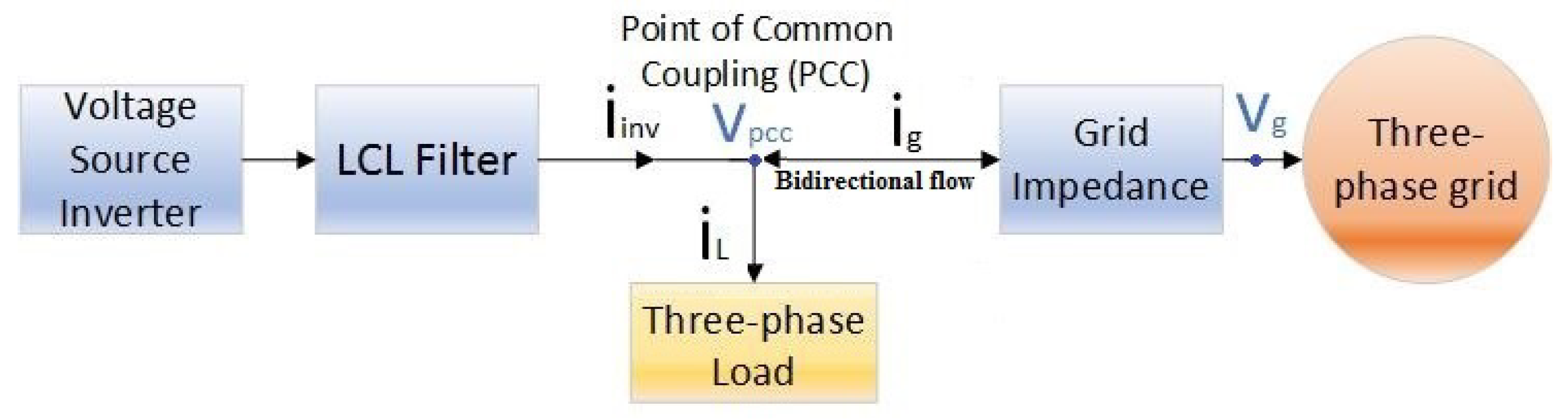
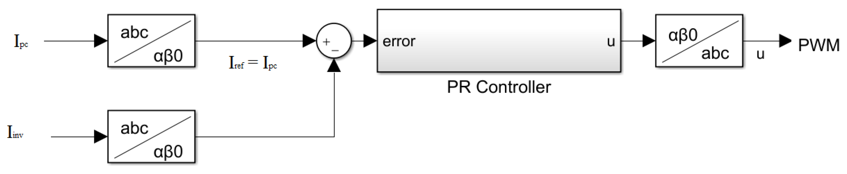
2. Current Control of Grid-Connected Three-Phase Inverter under Unbalanced Conditions

Figure 1 presents the system under investigation in this paper. Power is transferred from/to the grid through a three-phase inverter and LCL filter. For the proposed control approach, the grid currents i g , the inverter injected currents i i n v , the load currents i L , as well as the voltages at the v p c c , and the grid voltages v g , are monitored. A battery system can be used as a power source for the three-phase voltage source inverter.
The per-phase LCL filter transfer function [31] is presented in Equation (1)
i i n v ( s ) v g ( s ) = R D C S + 1 L 1 L 2 C S 3 + R D ( L 1 + L 2 ) C s 2 + ( L 1 + L 2 ) s
where R D is the damping resistor, L 1 is the inverter side inductance, L 2 is the grid side inductance, and C is the capacitance of the filter.
In [31], the output current of a three-phase inverter was controlled using a typical PR controller. The PR controller’s transfer function was expressed as in Equation (2).
G P R ( s ) = K P + K r s s 2 + ω 0 2
where K p is the proportional coefficient, K r is the resonant coefficient, and ω 0 is the fundamental frequency.
The PR controller will balance the inverter’s output current if the three-phase reference currents are considered to be balanced. For simplification, the reference currents and measurement currents were converted from a b c to α β 0 utilizing a Clarke transformation [32]. The controller could then only be used in two-phases ( α β ) , as illustrated in Figure 2.
Power can be transferred from the inverter to the grid and vice versa. Assuming power flow into the grid ( i g injected to the grid) and applying Kirchhoff’s current law to the PCC yields Equation (3):
i i n v = i g + i L
The PR controller has the ability to make the inverter current equal to the desired current ( i i n v = i r e f = i p c ) ; i p c is the reference power command current.
i p c = i g + i L i g = i p c i L
Using Equation (4), the PR controller can balance and control grid currents by adding extra feedback from the load current. The PR controller parameters K p and K r can be tuned using [33]. Figure 3 shows the suggested technique.

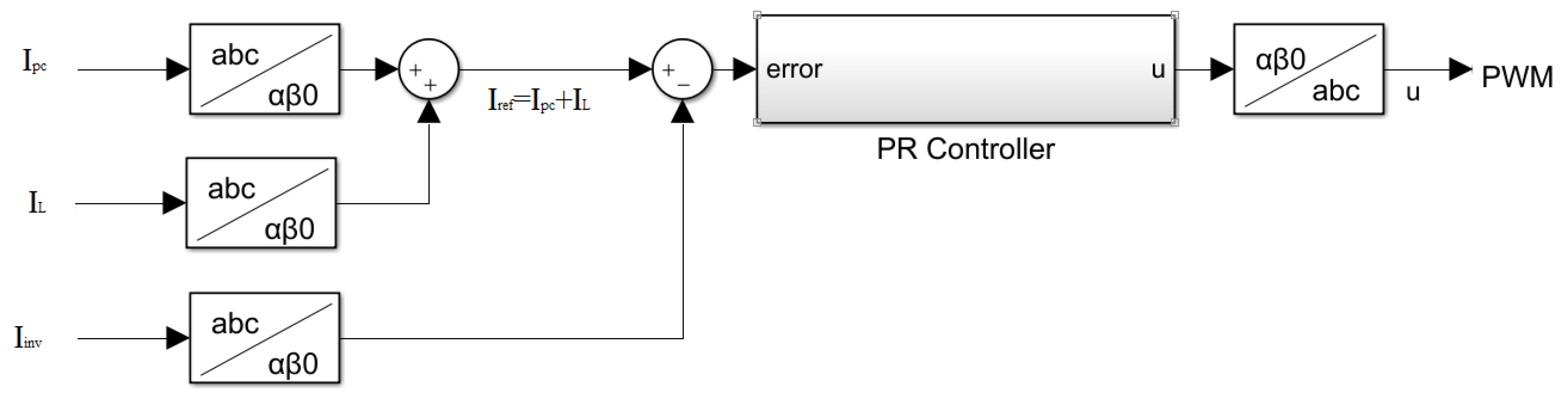
3. Power Control of Grid-Connected Three-Phase Inverter under Unbalanced Conditions

Based on Equation (4), the desired reference current i p c can be utilized for bidirectional power control. As illustrated in Equation (5), the reference current or the power command current i p c could be obtained from the desired real and reactive power and the measured PCC voltages as in [34].
S ¯ = P + j Q = V α β 0 T i α β 0 *
P + j Q = V α i α * + V β i β * + 2 V 0 i 0 *
Equation (6) shows that the PCC voltages play an important role in the reference current calculations.

3.1. Unbalanced Three-Phase Load Condition Neglecting the Grid Impedance

When the grid impedance is neglected under balanced three-phase grid voltages and unbalanced three-phase loads, the unbalanced grid currents yield oscillations in the real and reactive power as shown in Figure 4.
Under balanced PCC voltages, the zero component ( V 0 ) is zero. As a result, the term 2 v o i 0 will be ignored. The complex power equation can be simplified as in [34]:
P + j Q = v α β i α β * = v α + j v β i α j i β
P + j Q = v α i α + v β i β + j v β i α v α i β
P Q = v α v β v β v α i α i β
where S ¯ is the complex power injected to the grid, P is the real power injected to the grid, Q is the reactive power injected to the grid, V α β 0 are the PCC voltages in the Clarke transformation domain α β 0 , and i α β 0 are the grid currents in the α β 0 domain.
By re-arranging the terms, the reference current (power command current i p c in the α β 0 domain) can be determined using the Equation (8). Figure 5 shows the block diagram for calculating the reference current.
i α i β = 1 v α 2 + v β 2 v α v β v β v α P Q

3.2. Unbalanced Three-Phase Load Condition including Balanced and Unbalanced Grid Impedance
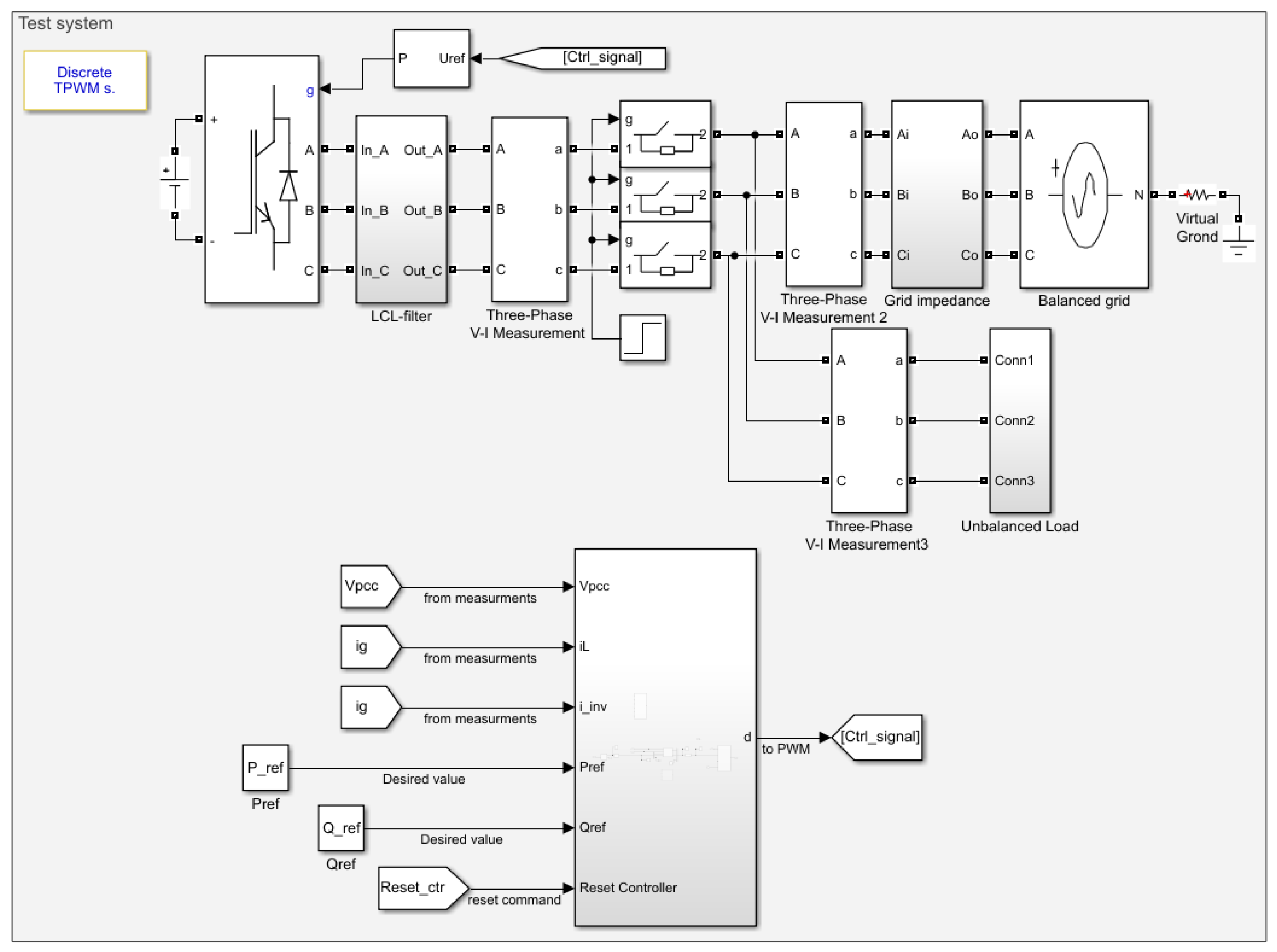
When the grid impedance is considered under balanced grid voltages and an unbalanced load, then both the grid currents and the PCC voltages will be unbalanced as shown in Figure 6.
In this situation, the assumption of the zero component of PCC voltages ( V 0 ) = 0 is no longer valid, which means the equations discussed in Section 3.1 and in reference [31] are no longer valid.
To find a solution to this problem, the PCC voltages can be separated into symmetrical components (positive, negative, and zero sequences). Therefore, the fundamental balanced part of the PCC voltage (the positive symmetrical component of the grid voltage V a b c + ) will be taken into consideration in the reference current calculations. The symmetrical extraction component method in [14] can be used to extract the symmetrical components of the PCC voltages. By having a balanced V a b c + , then the assumption ( V 0 + ) = 0 will be valid and the reference current can be calculated easily by using only the positive symmetrical component V a b c + instead of all components of the PCC voltage V a b c in the equations of Section 3.1 and shown in Equation (9). Figure 7 shows the new modified block diagram for reference current calculation.
i α i β = 1 v α + 2 + v β + 2 v α + v β + v β + v α + P Q
Since the balanced components of V p c c have been used, then the reference current calculation method in Equation (9) and Figure 7 can be used as a general case under either balanced or unbalanced V p c c .
Figure 8 shows the complete block diagram of the control system using a PR controller.

4. Case Studies

The suggested methodology was validated using simulation and hardware studies. The simulation is performed in MATLAB/SIMULINK. A three-phase AgileSwitch 100 kW DC-AC Inverter and a dSPACE DS1202 were utilized in the hardware experiment. Table 1 lists the system parameters. Reference [35] was employed to select LCL filter design parameters, while [33] was used to optimize the PR controller settings.
The system was operated under unbalanced grid impedance with values of L a = 5.1 mH , L b = 4.5 mH , and L c = 3 mH . The three-phase load was assumed to be unbalanced with R a = 8 Ω , R b = 16 Ω , and R c = 32 Ω . The grid voltages were assumed to be balanced at 120 V RMS. Since the grid impedance was considered under an unbalanced load, then both the grid currents and the PCC voltages will be unbalanced as discussed in Section 3.2.

4.1. Simulation Results
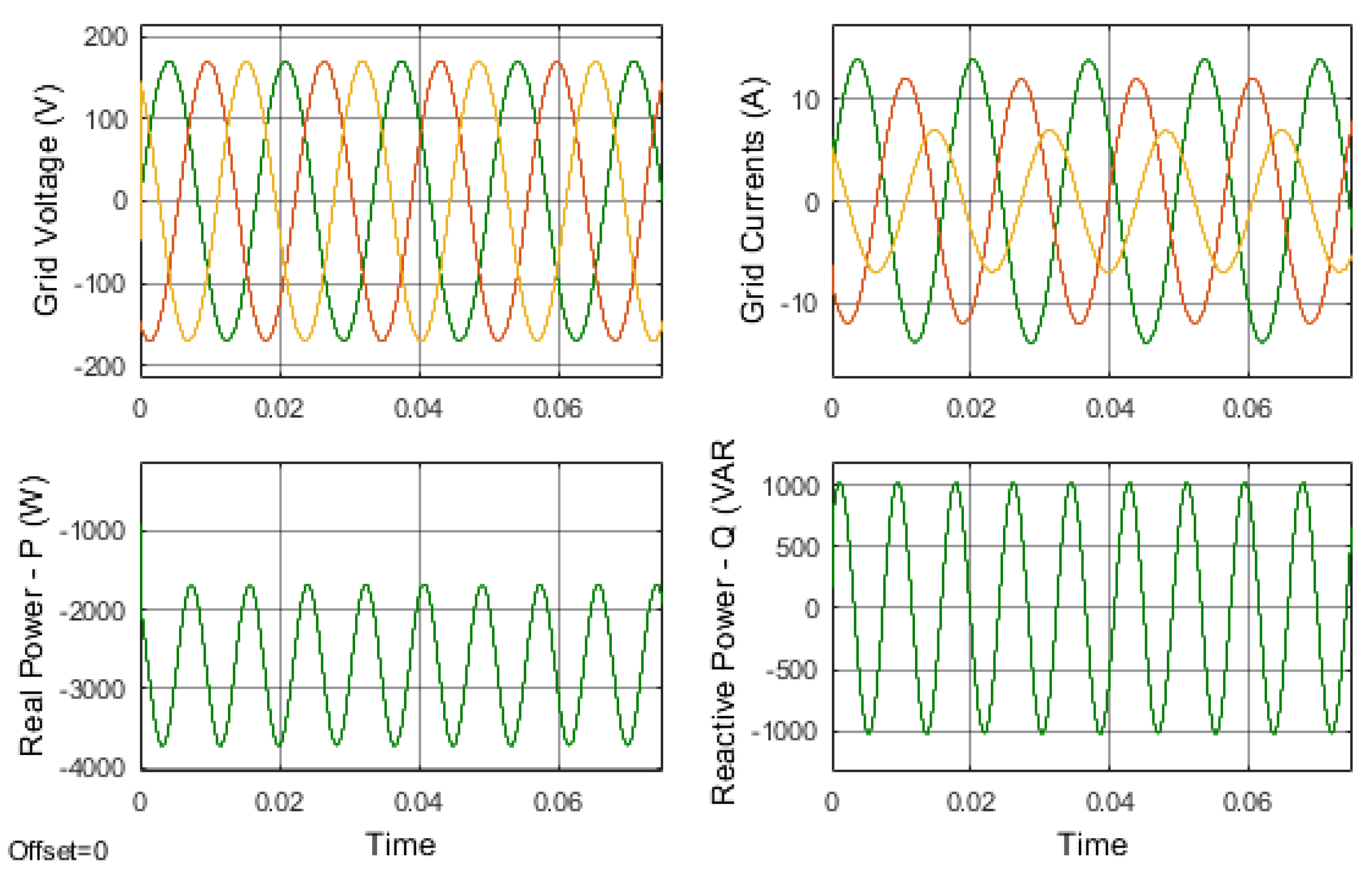
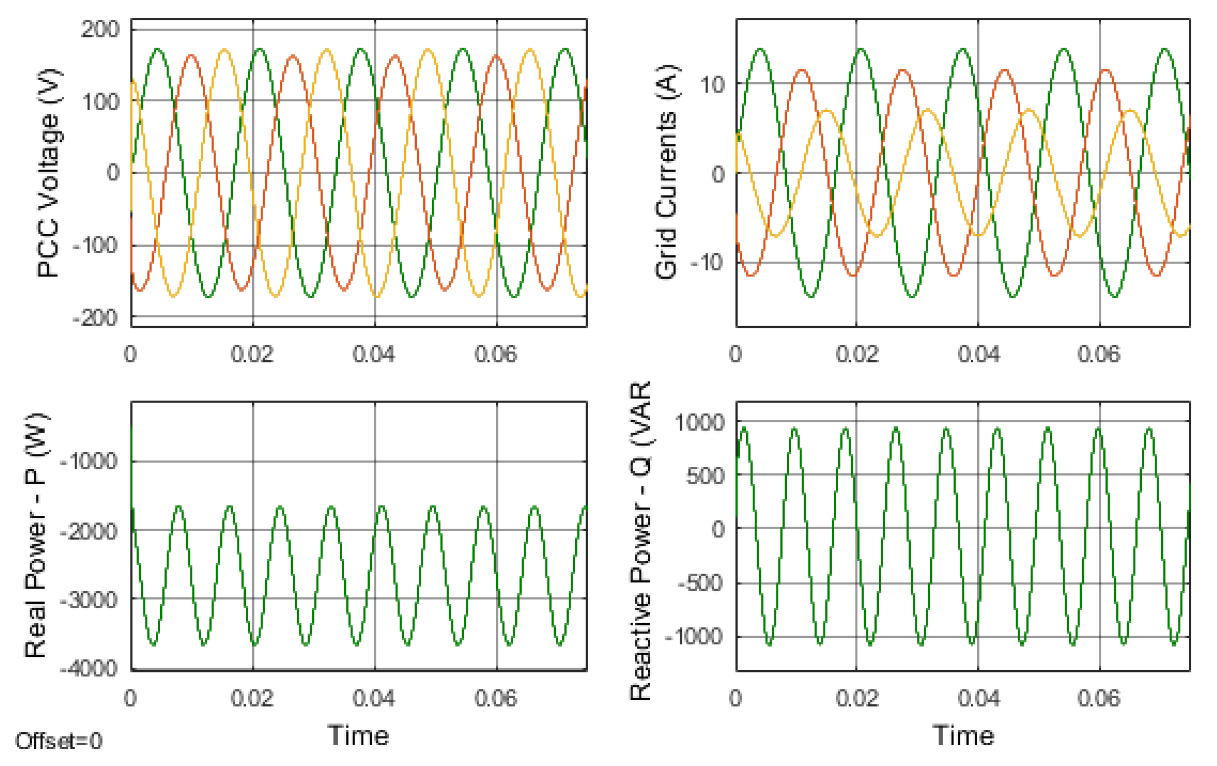
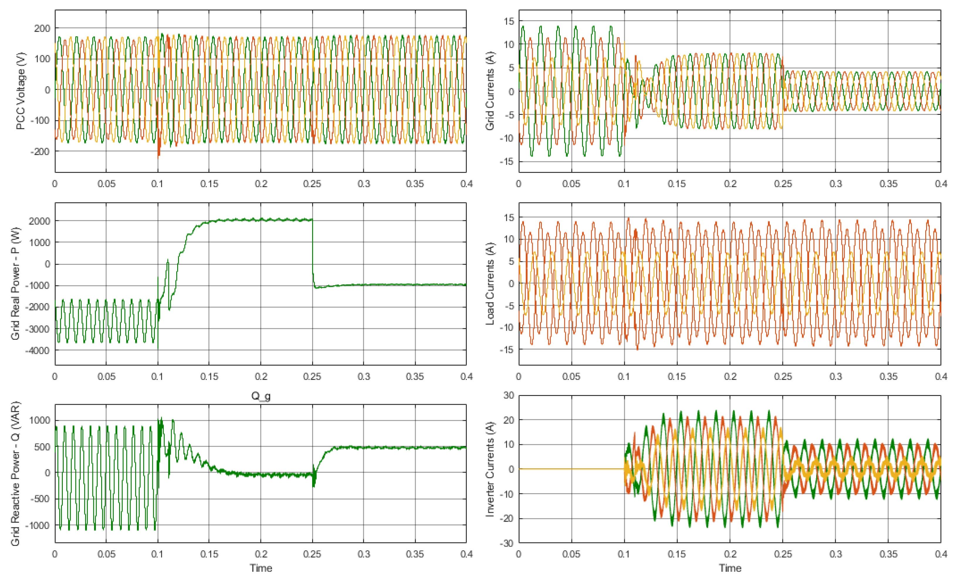
P d e s i r e d , Q d e s i r e d and the positive symmetrical component of V p c c are used to obtain the power command current i p c for power control, as explained in Equation (9). The Simulink model for the system is shown in Figure 9. Assume that the three-phase grid-connected inverter was energized at t = 0.1 s with P d e s i r e d = 2 kW and Q d e s i r e d = 0 var . At t = 0.25 s , the desired values have been changed to be P d e s i r e d = 1 kW and Q d e s i r e d = 500 var .
The simulation results for the real and reactive power injected into the grid, load currents ( i L ) , grid currents ( i g ) and inverter injected currents ( i i n v ) are shown in Figure 10.
  • For t < 0.1 s in simulation time, the unbalanced load was connected to the grid. At this time, both the grid currents and the PCC voltages are unbalanced. Furthermore, the P and Q waveforms of the grid are oscillatory. Other loads linked to the PCC were affected by the unbalanced system.
  • At t = 0.1 s , the inverter was turned on and connected to the grid.
  • For 0.1 < t < 0.25 s , the control approach injected into the grid the desired real and reactive power (2 kW, 0 var) while balancing grid currents during a few milliseconds. Since both the grid currents and PCC voltages are now balanced, the large variations in P and Q are no longer present. By supplying the desired power into the grid and balancing PCC voltages and grid currents, the effectiveness of the recommended strategy has been proven based on the simulation findings.
  • At t > 0.25 s, the injected desired real and reactive power to the grid has been changed to be (−1 kW, 500 var). The negative sign means that the inverter is absorbing real power. The controller took a few milliseconds to correct and track the new desired power value. With these findings, the controller method can be applied to bidirectional power control under unbalanced grid situations.

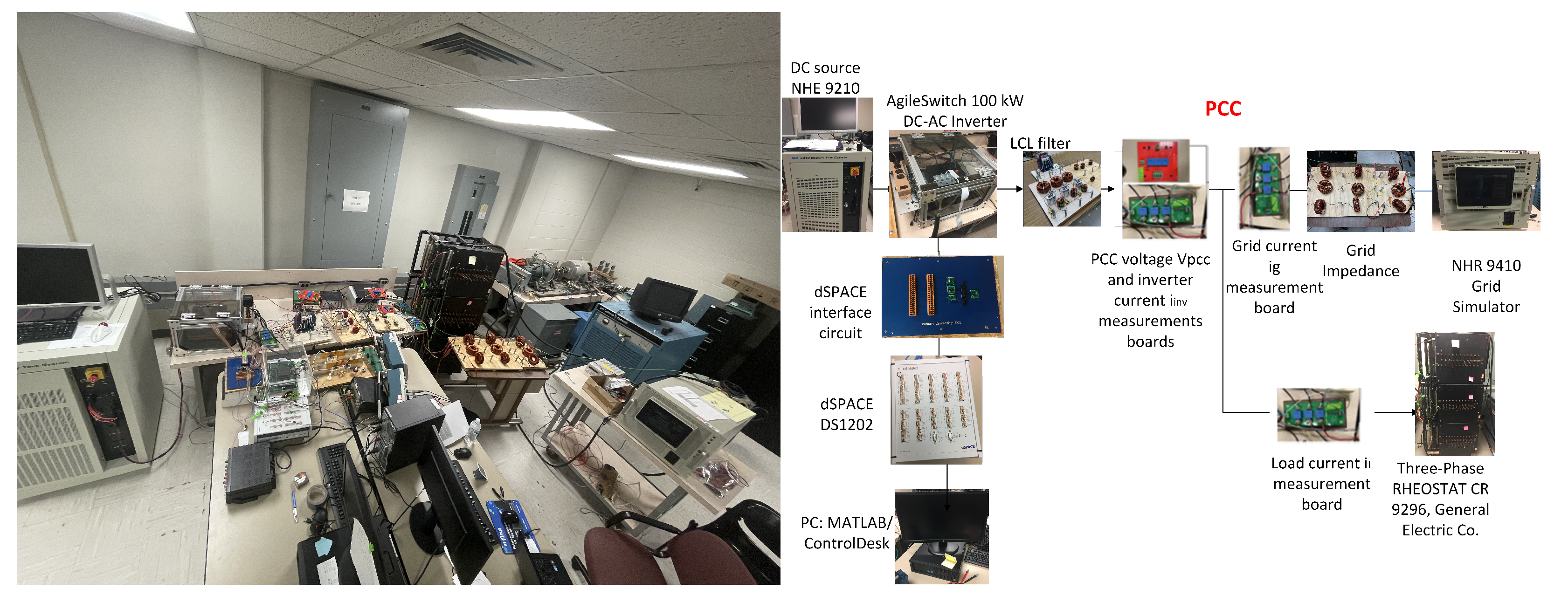
4.2. Experimental Results

The hardware experiments were performed utilizing the system parameters in Table 1. A battery test system that acts as a DC source (NHR 9210), a DC-AC inverter (AgileSwitch 100 kW), a real-time interface (RTI) (dSPACE DS1202), an LCL filter, a grid simulator (NHR 9410), and current and voltage measuring boards comprised the experimental setup. Variable resistors (RHEOSTAT CR 9296 General Electric Company, Boston, MA, USA) were used as the three-phase load. Figure 11 represents the hardware system setup.
The same conditions in the simulation were applied to the hardware setup. The unbalanced grid impedance values were 5.1 mH, 4.5 mH, and 3 mH, and the unbalanced loads were 8 Ω, 16 Ω and 16 Ω for phases A, B and C, respectively. Under this scenario, both the grid currents and the PCC voltages will be unbalanced.
Different power control cases have been studied as follows:
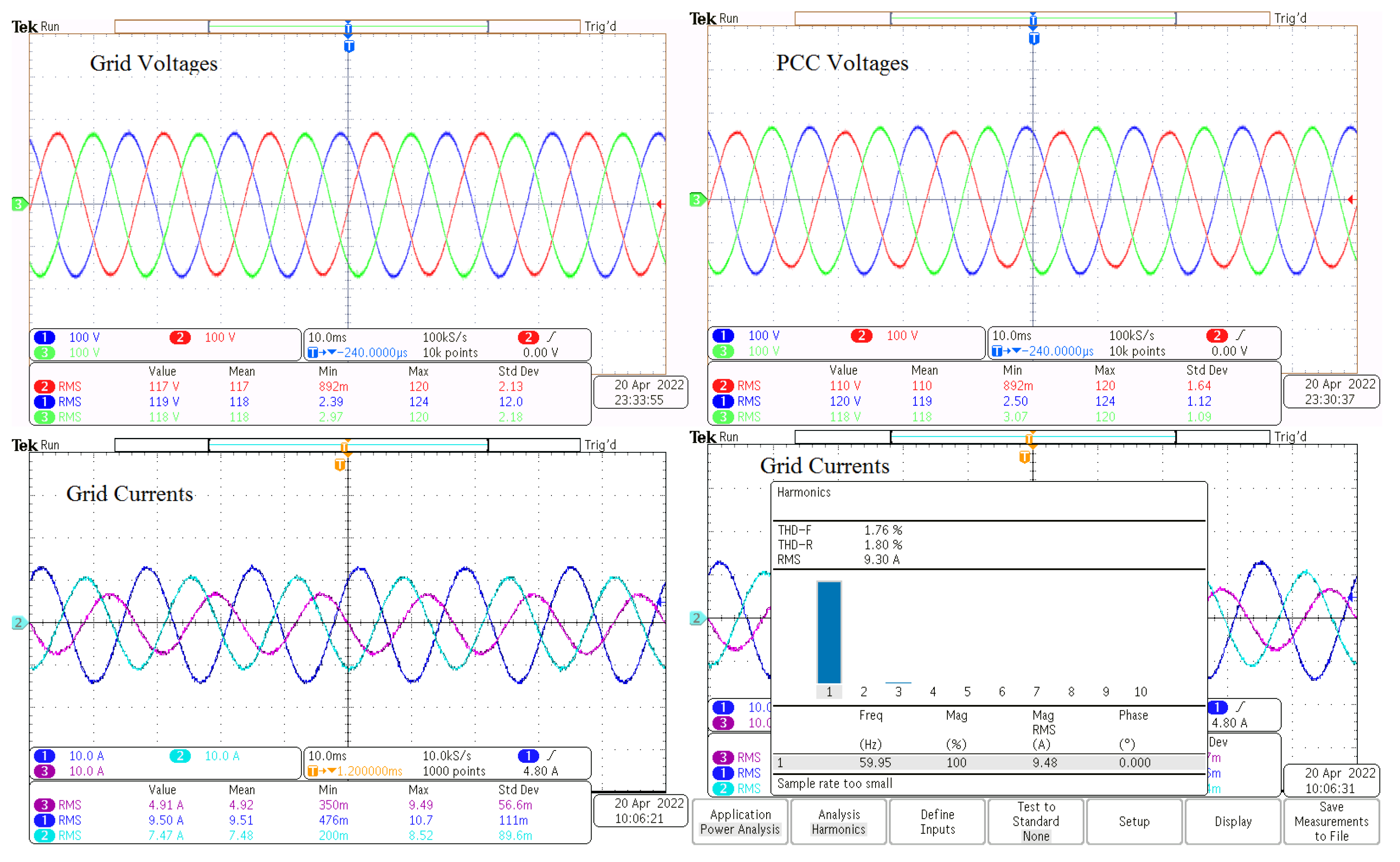
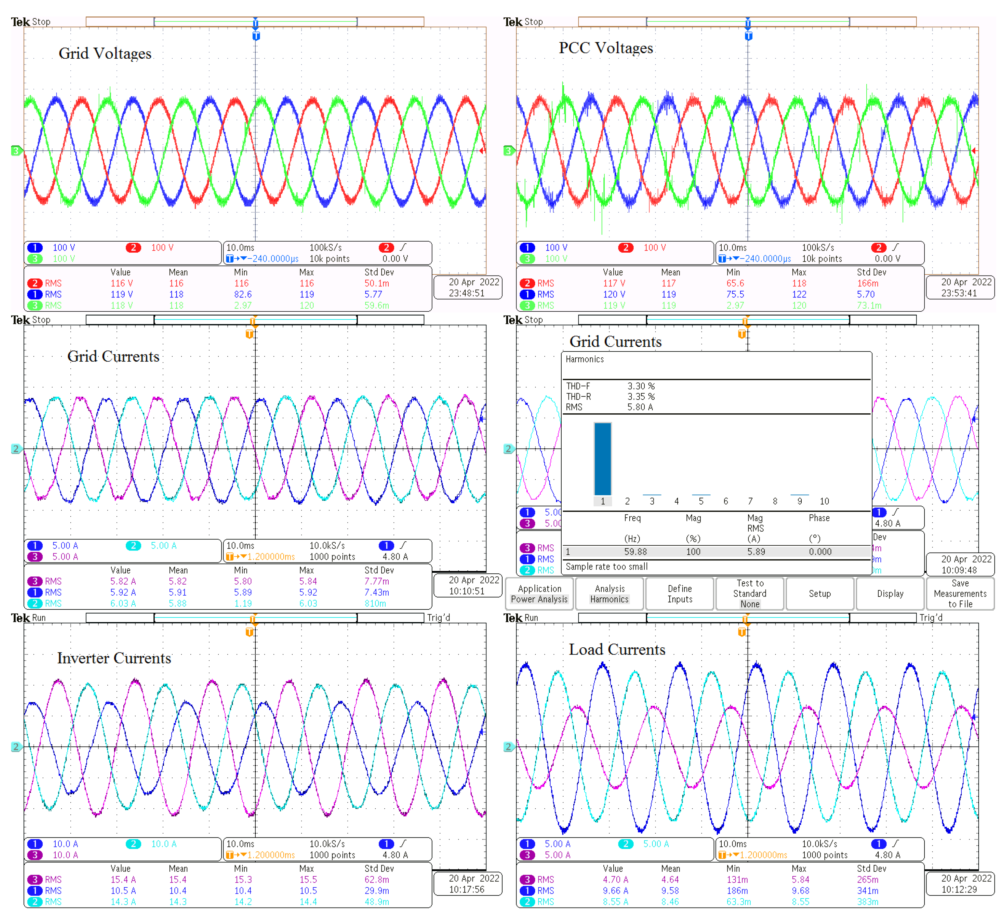
  • The grid was initially assumed to be connected to the load without connecting the inverter. In this case, the grid currents and PCC voltages will be unbalanced, while the grid voltages were balanced as shown in Figure 12. These results were captured using a Tektronix MDO3024 oscilloscope.
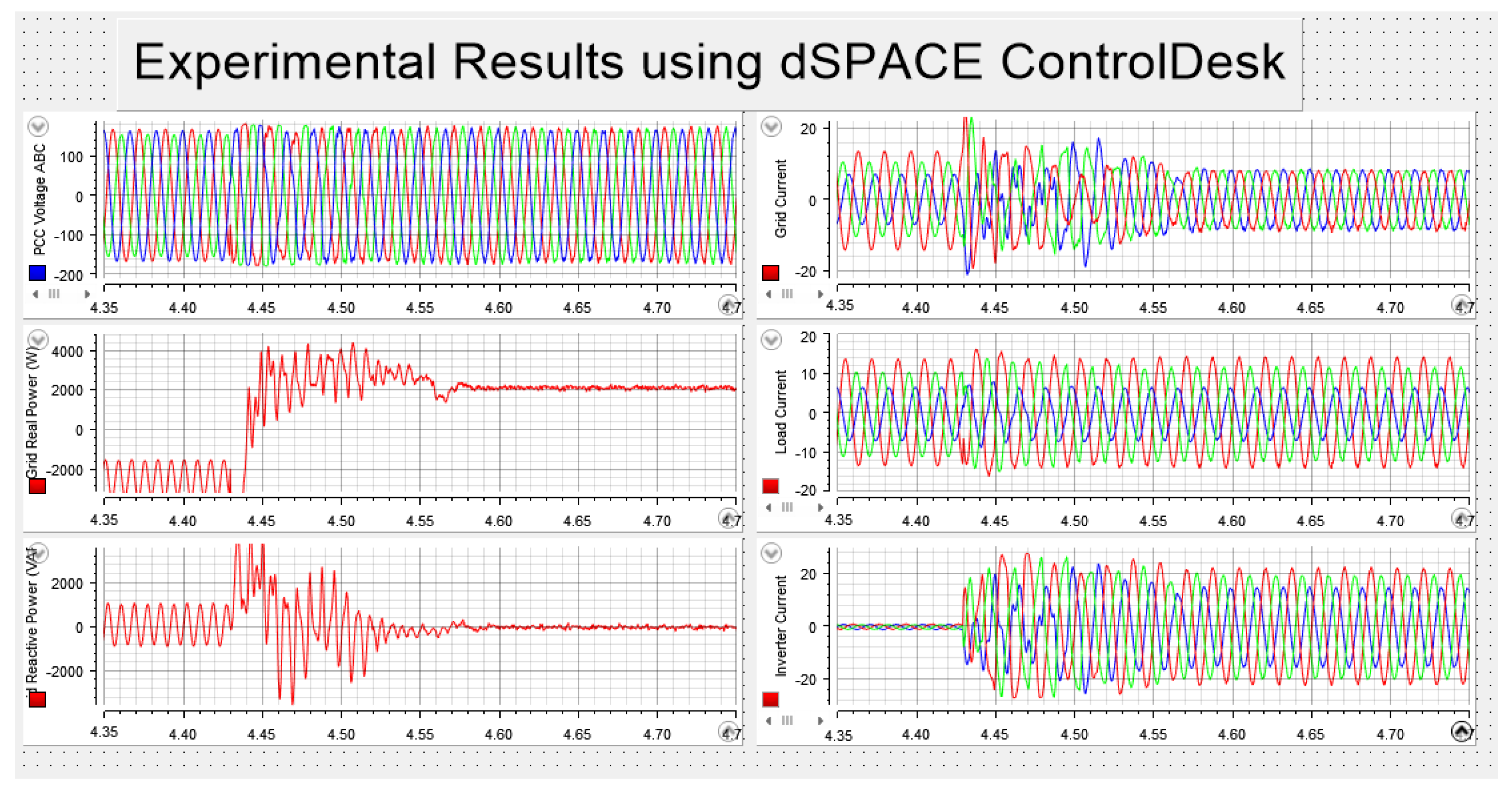
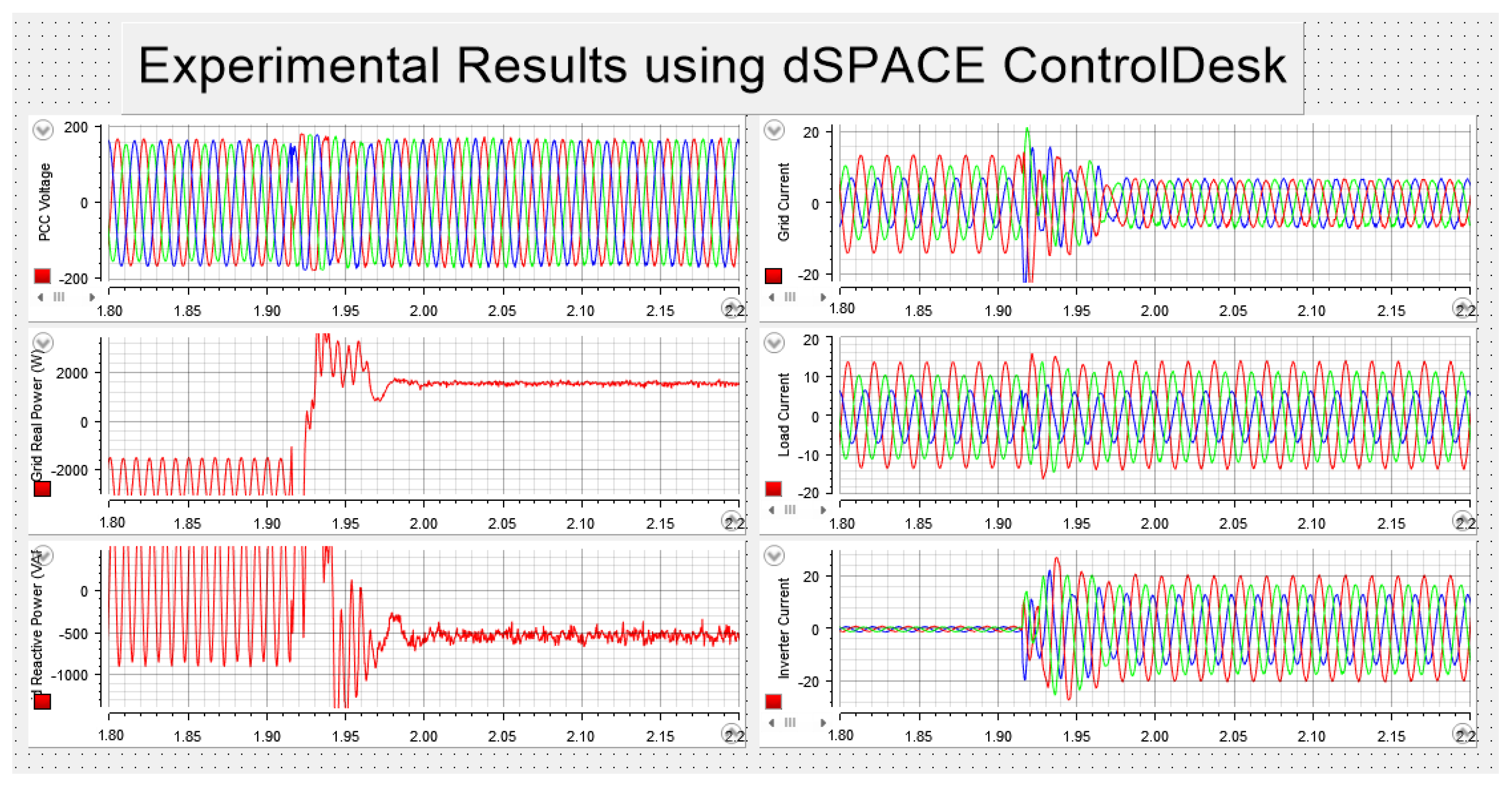
  • The inverter was energized and the proposed method was applied assuming P d e s i r e d = 2 kW and Q d e s i r e d = 0 var . The system took a few milliseconds to balance the grid currents, balance the PCC voltages, and power control. Figure 13 displays the experimental data, which was obtained using the dSPACE ControlDesk toolbox. Figure 14 shows the experimental results for grid voltages, PCC voltages, grid currents, inverter currents, and load currents obtained using a Tektronix MDO3024 oscilloscope. The value of the total harmonic distortion percentage (%THD) for the grid currents is 3.3%. This is considered an acceptable value. This proposed method aims to achieve power control as well as clear the unbalance of the grid currents, so the contribution doesn’t include improving the %THD.
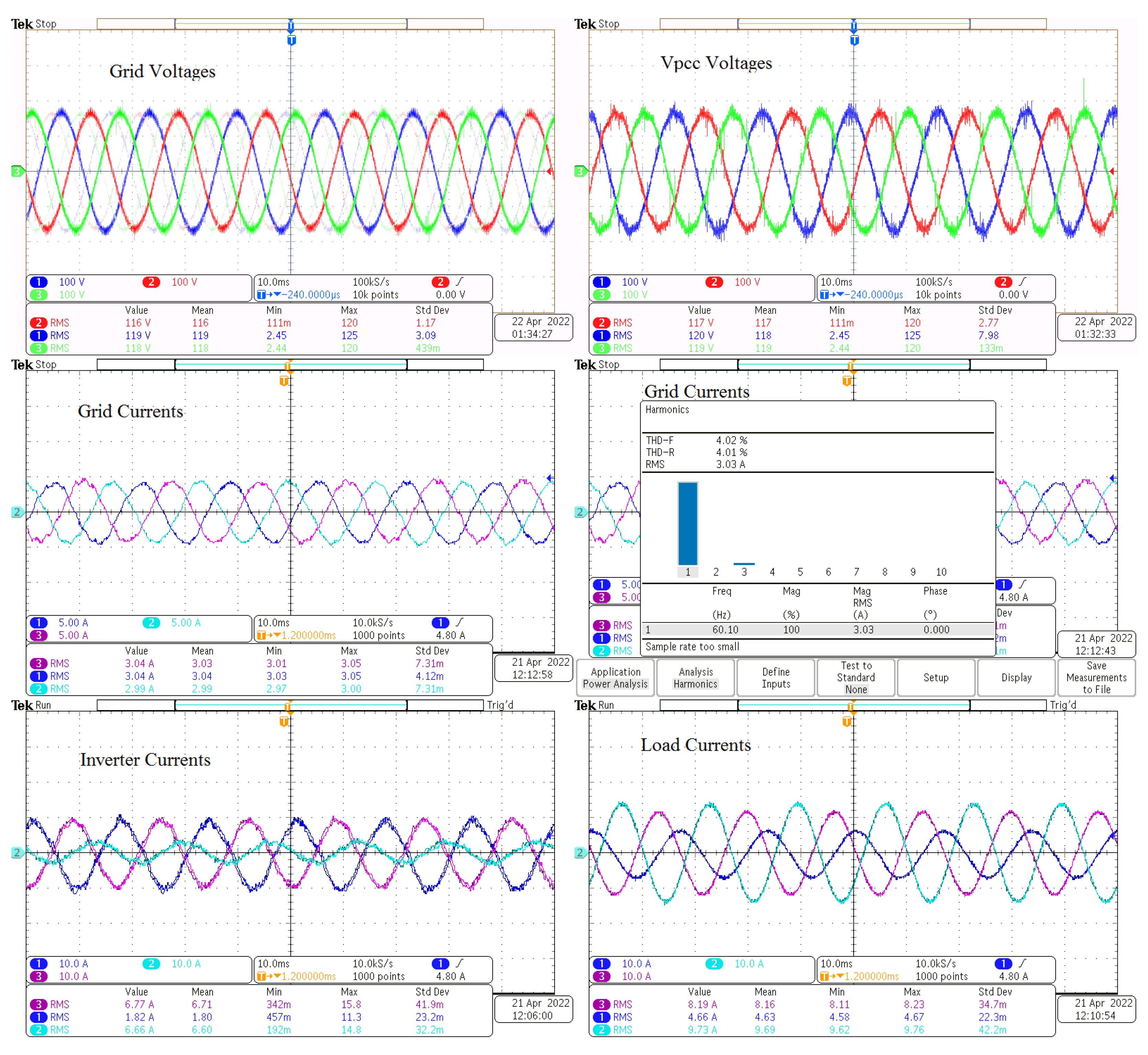
  • Assuming the P d e s i r e d = 1 kW and Q d e s i r e d = 500 var , the system can do bidirectional power control as well as balancing the grid currents and the PCC voltages. Figure 15 shows the experimental results using the oscilloscope. The %THD of the grid currents is 4.0%. Figure 16 displays the experimental data using the dSPACE ControlDesk toolbox.
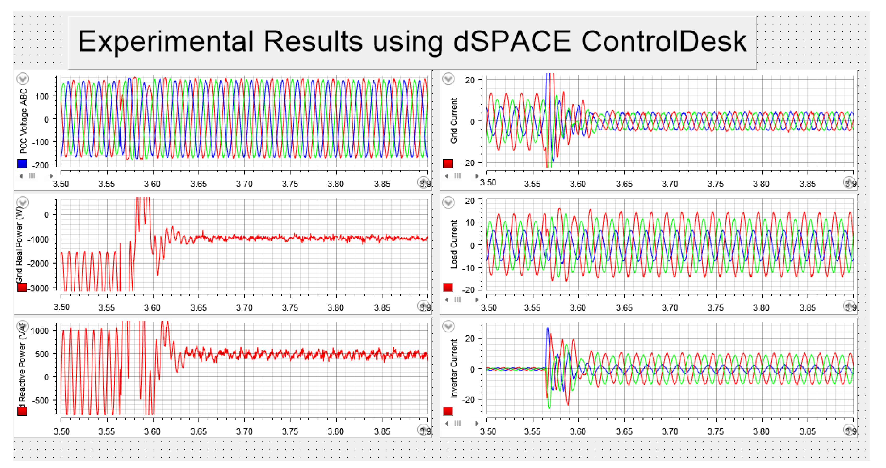
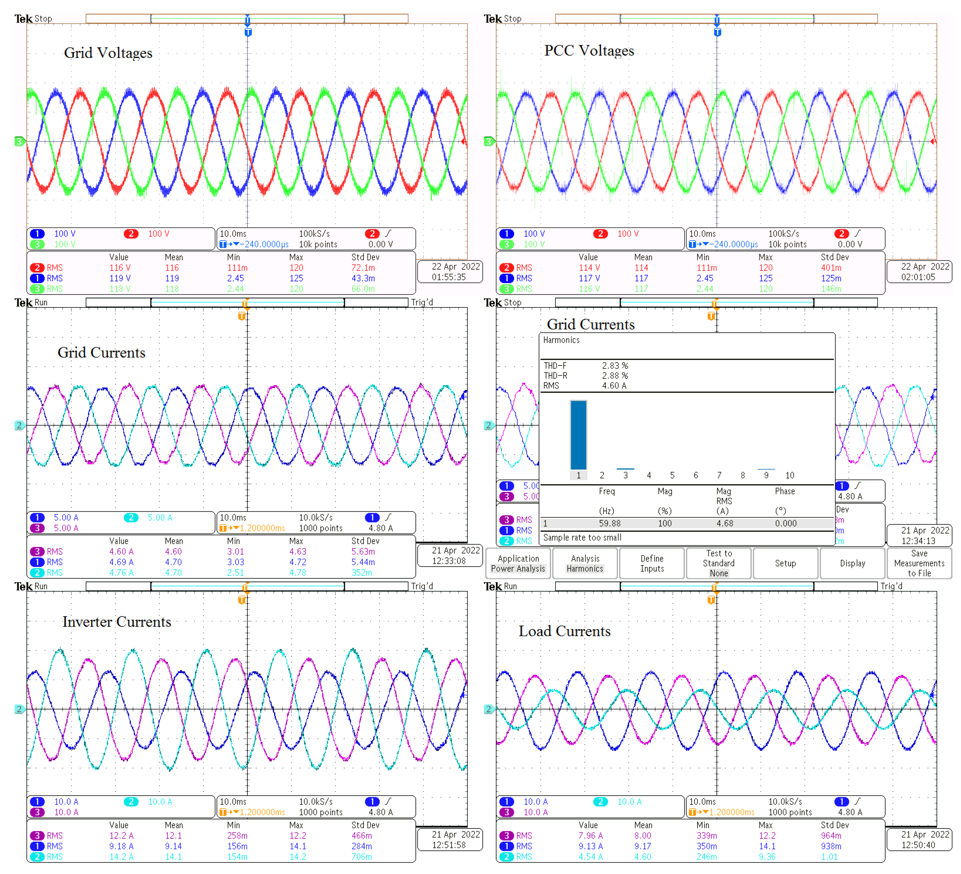
  • At P d e s i r e d = 1.5 kW and Q d e s i r e d = 500 var , the system can work in four-quadrant power control in addition to balancing the grid currents and the PCC voltages. Figure 17 shows the results obtained using the Tektronix MDO3024 oscilloscope. The %THD of the grid currents is 2.83%. Figure 18 displays the experimental data using the dSPACE ControlDesk toolbox.
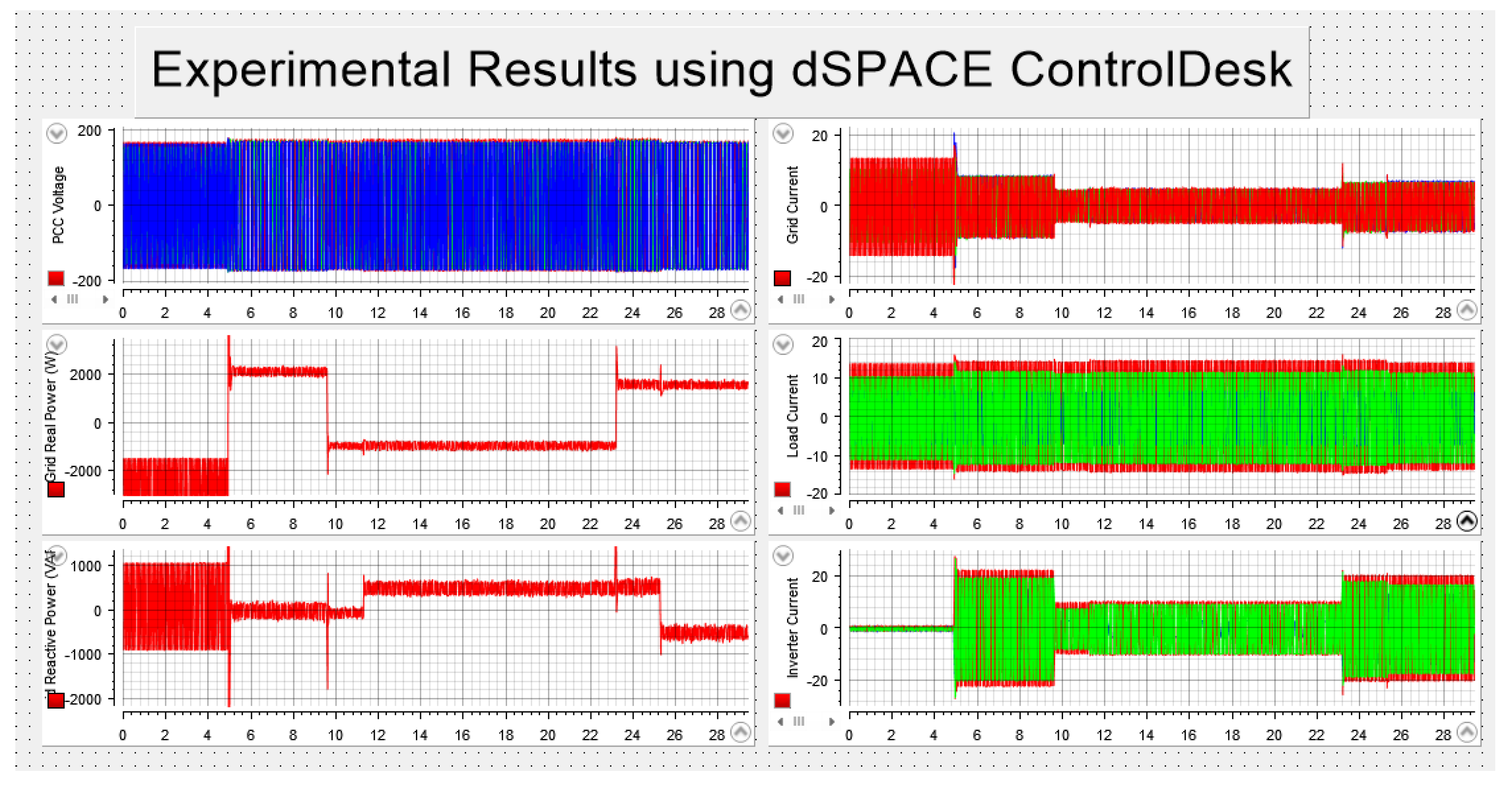
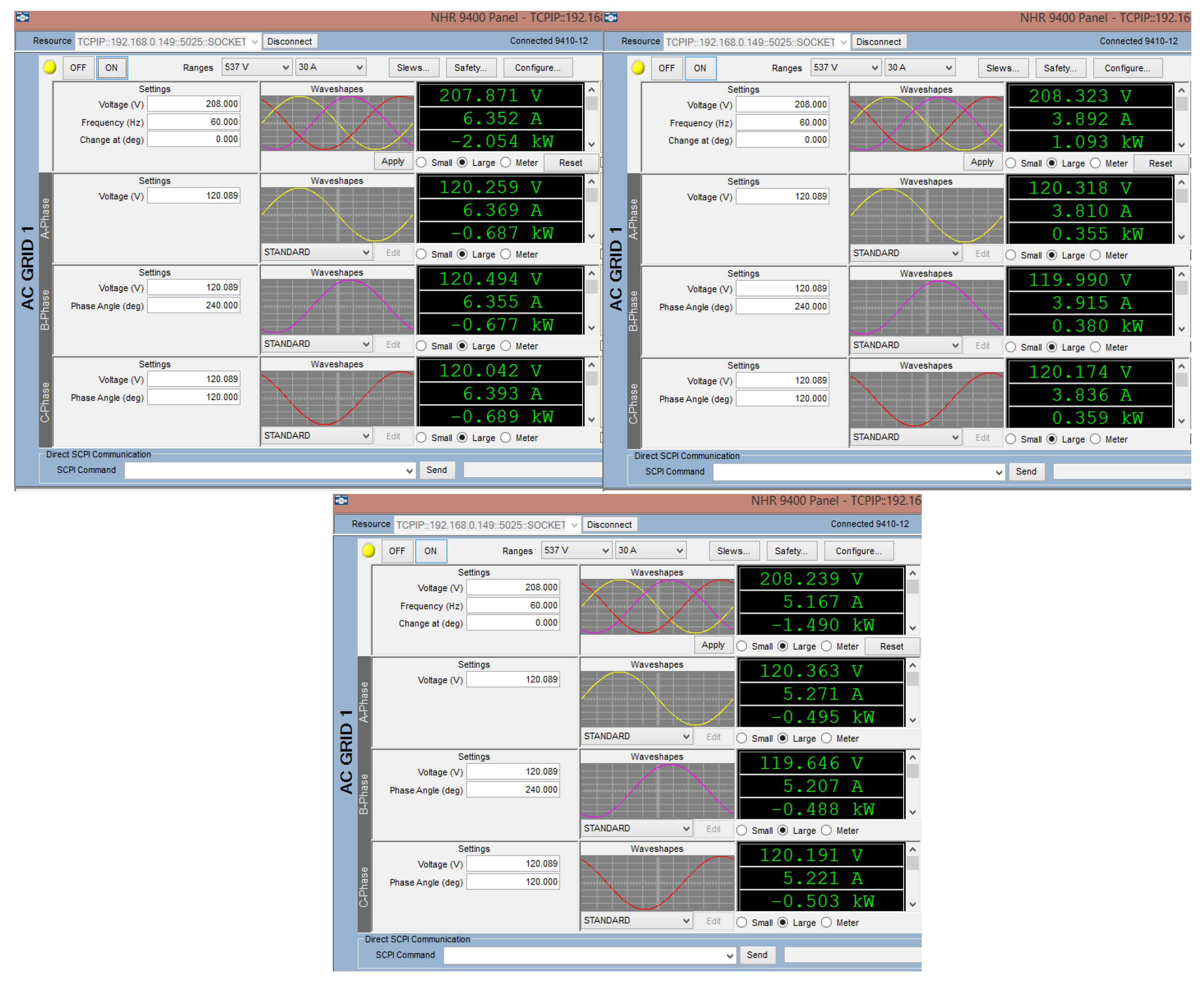
  • The system has been tested with multiple scenarios as shown in Figure 19. At t = 4.5 s , P d e s i r e d = 2 kW and Q d e s i r e d = 0 var . Then, P d e s i r e d = 1 kW at t = 9.5 s and Q d e s i r e d = 500 var at t = 11 s . At t = 23 s , the desired power was assumed as P d e s i r e d = 1.5 kW , and at t = 25 s   Q d e s i r e d = 500 var . The NHR 9400 Panel was used to obtain the grid simulator readings.
Figure 20 represents the real power sent to the grid as the required value with a small error. The negative sign means the real power is delivered into the grid, while the positive sign means the real power direction is out of the grid.
These observations indicate that the proposed technique can provide bidirectional power control under unbalanced grid operation, as well as balance grid currents and PCC voltages.
The proposed approach contributes to balancing PCC voltages because, in the cases presented, the voltage unbalance is caused by the unbalanced currents and grid impedances. If the unbalance source was the grid source voltages, the proposed inverter control would only reduce the unbalanced ratio of the PCC voltages.
To calculate the error, the following formula was utilized:
% Relative Error = | Experimental Simulated Experimental | × 100 %
Based on Equation (10), the relative error for real and reactive power for all three cases is shown in Table 2

5. Conclusions

Demonstrated in this article is the use of a three-phase inverter to inject power into or absorb power from the grid in the situation of an unbalanced load and unbalanced grid impedances. Real and reactive power fluctuate under these unbalanced grid situations, impacting the power control of the inverter and other three-phase loads connected to the grid. The PCC voltages and grid currents are unbalanced too under these scenarios.
The proposed approach using the PR controller achieves all three aims at once: grid current balancing, PCC voltage balancing, and bidirectional grid power control. For reference power calculations, the positive sequence components of the unbalanced PCC voltages were utilized. The PCC voltages and currents are both balanced, which makes the real and reactive power fluctuations significantly lower. Because a PR controller was used, there was no need for a PLL. Different simulation and hardware testing results verify the proposed technique’s efficacy.

Author Contributions

Conceptualization, M.A., H.G. and R.M.N.; methodology, M.A.; software, M.A.; validation, M.A., H.G., X.Y. and R.M.N.; formal analysis, M.A.; investigation, M.A., H.G., X.Y. and R.M.N.; supervision, R.M.N. All authors have read and agreed to the published version of the manuscript.

Funding

This research received no external funding.

Data Availability Statement

Not applicable.

Conflicts of Interest

The authors declare no conflict of interest.

Abbreviations

The following abbreviations are used in this manuscript:
APFActive power filters
DDSRF PLLDecoupled double synchronous reference frame phase-locked loop
DPD-SRDirect phase-angle detection
EPREnhanced proportional-resonant controller
ESSEnergy storage systems
MPRSmodified PR control strategy
PCCPoint-of-common-coupling
PIProportional-integral
PLLPhase-locked loop
PRProportional-resonant
RESRenewable energy resources

References

  1. Blaabjerg, F.; Chen, Z.; Kjaer, S. Power Electronics As Efficient Interface In Dispersed Power Generation Systems. IEEE Trans. Power Electron. 2004, 19, 1184–1194. [Google Scholar] [CrossRef]
  2. Lasseter, R. Smart Distribution: Coupled Microgrids. Proc. IEEE 2011, 99, 1074–1082. [Google Scholar] [CrossRef]
  3. ABB. Energy Storage Keeping Smart Grids in Balance. 2012. Available online: https://library.e.abb.com/public/59a2be960fdb777a48257a680045c04a/ABB%20Energy%20Storage_Nov2012.pdf (accessed on 21 September 2022).
  4. Choi, W.; Morris, C.; Sarlioglu, B. Modeling three-phase grid-connected inverter system using complex vector in synchronous dq reference frame and analysis on the influence of tuning parameters of synchronous frame PI controller. In Proceedings of the 2016 IEEE Power and Energy Conference at Illinois (PECI), Urbana, IL, USA, 19–20 February 2016; pp. 1–8. [Google Scholar]
  5. Liu, Y.; Bai, R.; Wang, D.; Ma, W.; Wang, L. Proportional-Resonant Control Method Of Three-Phase Grid-Connected Inverter. In Proceedings of the 26th Chinese Control and Decision Conference (2014 CCDC), Changsha, China, 31 May–2 June 2014; pp. 4797–4800. [Google Scholar]
  6. Definitions of Voltage Unbalance. IEEE Power Eng. Rev. 2002, 22, 49–50. [CrossRef]
  7. Li, P.; Dan, B.; Yong, K.; Jian, C. Research on three-phase inverter with unbalanced load. In Proceedings of the Nineteenth Annual IEEE Applied Power Electronics Conference and Exposition, Anaheim, CA, USA, 22–26 February 2004; Volume 1, pp. 128–133. [Google Scholar]
  8. Kalaivani, C.; Rajambal, K. Grid Integration of Three-phase Inverter using Decoupled Double Synchronus Reference Frame PLL. In Proceedings of the 2019 International Conference on Computation of Power, Energy, Information and Communication (ICCPEIC), Piscataway, NJ, USA, 27–28 March 2019; pp. 221–226. [Google Scholar]
  9. Sadeque, F.; Benzaquen, J.; Adib, A.; Mirafzal, B. Direct Phase-Angle Detection for Three-Phase Inverters in Asymmetrical Power Grids. IEEE J. Emerg. Sel. Top. Power Electron. 2021, 9, 520–528. [Google Scholar] [CrossRef]
  10. Miletic, Z.; Tremmel, W.; Br¨undlinger, R.; St¨ockl, J.; Bletterie, B. Optimal control of three-phase PV inverter under Grid voltage unbalance. In Proceedings of the 2019 21st European Conference on Power Electronics and Applications (EPE ’19 ECCE Europe), Genova, Italy, 3–5 September 2019; pp. 1–11. [Google Scholar]
  11. Alathamneh, M.; Yang, X.; Nelms, R.M.; Al-Gahtani, S. Power Control of a Three-phase Grid-connected Inverter using a PI Controller under Unbalanced Conditions. In Proceedings of the SoutheastCon 2022, Mobile, AL, USA, 26 March–3 April 2022; pp. 447–452. [Google Scholar]
  12. Al-Gahtani, S.; Nelms, R.M. A Modified IRPT Control Method for a Shunt Active Power Filter for Unbalanced Conditions. In Proceedings of the 2019 IEEE 28th International Symposium on Industrial Electronics (ISIE), Vancouver, BC, Canada, 12–14 June 2019; pp. 720–727. [Google Scholar]
  13. Al-Gahtani, S.; Nelms, R.M. A New Voltage Sensorless Control Method for a Shunt Active Power Filter for Unbalanced Conditions. In Proceedings of the 2019 IEEE International Conference on Environment and Electrical Engineering and 2019 IEEE Industrial and Commercial Power Systems Europe (EEEIC/ICPS Europe), Genova, Italy, 11–14 June 2019; pp. 1–6. [Google Scholar]
  14. Alathamneh, M.; Yang, X.; Nelms, R.M.; Al-Gahtani, S. Power Control of a Three-phase Grid-connected Inverter using a Time-Domain Symmetrical Components Extraction Method under Unbalanced Conditions. In Proceedings of the IECON 2021—47th Annual Conference of the IEEE Industrial Electronics Society, Toronto, ON, Canada, 13–16 October 2021; pp. 1–6. [Google Scholar]
  15. Alathamneh, M.; Ghanayem, H.; Yang, X.; Nelms, R.M. PR Controller for a Three-phase Grid-connected Inverter in an Unbalanced System using a Time-Domain Symmetrical Components Extraction Method. In Proceedings of the 2022 IEEE 31st International Symposium on Industrial Electronics (ISIE), Anchorage, AK, USA, 1–3 June 2022; pp. 18–23. [Google Scholar]
  16. Bak, Y.; Lee, J.-S.; Lee, K.-B. Balanced Current Control Strategy for Current Source Rectifier Stage of Indirect Matrix Converter under Unbalanced Grid Voltage Conditions. Energies 2017, 10, 27. [Google Scholar] [CrossRef]
  17. Mohammed, N.; Ciobotaru, M.; Town, G. Online Parametric Estimation of Grid Impedance Under Unbalanced Grid Conditions. Energies 2019, 12, 4752. [Google Scholar] [CrossRef]
  18. Chen, X.; Wu, W.; Gao, N.; Liu, J.; Chung, H.S.-H.; Blaabjerg, F. Finite Control Set Model Predictive Control for an LCL-Filtered Grid-Tied Inverter with Full Status Estimations under Unbalanced Grid Voltage. Energies 2019, 12, 2691. [Google Scholar] [CrossRef]
  19. Alharbi, M.; Isik, S.; Alkuhayli, A.; Bhattacharya, S. Power Ripple Control Method for Modular Multilevel Converter under Grid Imbalances. Energies 2022, 15, 3535. [Google Scholar] [CrossRef]
  20. Yu, Y.; Wang, Z.; Wan, X. Optimal Current Balance Control of Three-Level Inverter under Grid Voltage Unbalance: An Adaptive Dynamic Programming Approach. Energies 2019, 12, 2864. [Google Scholar] [CrossRef]
  21. Ma, W.; Ouyang, S.; Xu, W. Improved Frequency Locked Loop Based Synchronization Method for Three-Phase Grid-Connected Inverter under Unbalanced and Distorted Grid Conditions. Energies 2019, 12, 1023. [Google Scholar] [CrossRef] [Green Version]
  22. Wang, S.; Bao, D.; Gontijo, G.; Chaudhary, S.; Teodorescu, R. Modeling and Mitigation Control of the Submodule-Capacitor Voltage Ripple of a Modular Multilevel Converter under Unbalanced Grid Conditions. Energies 2021, 14, 651. [Google Scholar] [CrossRef]
  23. Tan, K.-H.; Lin, F.-J.; Chen, J.-H. A Three-Phase Four-Leg Inverter-Based Active Power Filter for Unbalanced Current Compensation Using a Petri Probabilistic Fuzzy Neural Network. Energies 2017, 10, 2005. [Google Scholar] [CrossRef]
  24. Shin, H.; Chae, S.H.; Kim, E.-H. Unbalanced Current Reduction Method of Microgrid Based on Power Conversion System Operation. Energies 2021, 14, 3862. [Google Scholar] [CrossRef]
  25. Nakadomari, A.; Shigenobu, R.; Kato, T.; Krishnan, N.; Hemeida, A.M.; Takahashi, H.; Senjyu, T. Unbalanced Voltage Compensation with Optimal Voltage Controlled Regulators and Load Ratio Control Transformer. Energies 2021, 14, 2997. [Google Scholar] [CrossRef]
  26. Najafi, F.; Hamzeh, M.; Fripp, M. Unbalanced Current Sharing Control in Islanded Low Voltage Microgrids. Energies 2018, 11, 2776. [Google Scholar] [CrossRef]
  27. Kim, J.-M.; Song, G.-S.; Jung, J.-J. Zero-Sequence Voltage Injection Method for DC Capacitor Voltage Balancing of Wye-Connected CHB Converter under Unbalanced Grid and Load Conditions. Energies 2021, 14, 1019. [Google Scholar] [CrossRef]
  28. Ahmed, E.M.; Aly, M.; Elmelegi, A.; Alharbi, A.G.; Ali, Z.M. Multifunctional Distributed MPPT Controller for 3P4W Grid-Connected PV Systems in Distribution Network with Unbalanced Loads. Energies 2019, 12, 4799. [Google Scholar] [CrossRef]
  29. Cai, H.; Zhang, P.; Zhao, H.; Shi, J.; Yao, W.; He, X. Controller design for three-phase inverter with power unbalanced loads applied in microgrids. In Proceedings of the 2015 IEEE Energy Conversion Congress and Exposition (ECCE), Montreal, QC, USA, 20–24 September 2015; pp. 4588–4593. [Google Scholar]
  30. Mishra, M.K.; Lal, V.N. An Enhanced Control Strategy for Harmonic Current Suppression of Grid-Connected PV System without PhaseLocked Loop Under Distorted Grid Voltage Conditions. In Proceedings of the IEEE Applied Power Electronics Conference and Exposition (APEC), Phoenix, AZ, USA, 14–17 June 2021; pp. 2702–2707. [Google Scholar]
  31. Alathamneh, M.; Yang, X.; Nelms, R.M. Power Control of a Three-phase Grid-connected Inverter using a Proportional-Resonant Control Method under Unbalanced Conditions. In Proceedings of the IECON 2021—47th Annual Conference of the IEEE Industrial Electronics Society, Toronto, ON, Canada, 13–16 October 2021; pp. 1–6. [Google Scholar]
  32. Duesterhoeft, W.C.; Schulz, M.W.; Clarke, E. Determination of Instantaneous Currents and Voltages by Means of Alpha, Beta, and Zero Components. Trans. Am. Inst. Electr. Eng. 1951, 70, 1248–1255. [Google Scholar] [CrossRef]
  33. Pereira, L.F.A.; Bazanella, A.S. Tuning Rules for Proportional Resonant Controllers. IEEE Trans. Control. Syst. Technol. 2015, 23, 2010–2017. [Google Scholar] [CrossRef]
  34. Akagi, H.; Kanazawa, Y.; Nabae, A. Instantaneous reactive power compensators comprising switching devices without energy storage. IEEE Trans. Ind. Appl. 1984, 20, 625–630. [Google Scholar] [CrossRef]
  35. Yang, X.; Alathamneh, M.; Nelms, R.M. Improved LCL Filter Design Procedure for Grid-Connected Voltage-Source Inverter System. In Proceedings of the 2021 IEEE Energy Conversion Congress and Exposition (ECCE), Vancouver, BC, Canada, 10–14 October 2021; pp. 3587–3591. [Google Scholar]
Figure 1. Three-phase grid connected system.
Energies 15 07051 g001
Figure 2. Current control using PR controller.
Energies 15 07051 g002
Figure 3. The proposed current control method using PR controller.
Energies 15 07051 g003
Figure 4. Neglecting the grid impedance under unbalanced load.
Energies 15 07051 g004
Figure 5. Reference current calculation under balanced PCC voltages.
Energies 15 07051 g005
Figure 6. Including the grid impedance under unbalanced load.
Energies 15 07051 g006
Figure 7. Reference current calculation under unbalanced PCC voltages.
Energies 15 07051 g007
Figure 8. The complete block diagram of the proposed method.
Energies 15 07051 g008
Figure 9. System’s Simulink model.
Energies 15 07051 g009
Figure 10. MATLAB/SIMULINK results.
Energies 15 07051 g010
Figure 11. Hardware test system.
Energies 15 07051 g011
Figure 12. Experimental results before energizing the inverter.
Energies 15 07051 g012
Figure 13. Experimental results at P = 2 kW, Q = 0 var using dSPACE Control desk.
Energies 15 07051 g013
Figure 14. Experimental results at P = 2 kW, Q = 0 var using Tektronix MDO3024 oscilloscope.
Energies 15 07051 g014
Figure 15. Experimental results at P = −1 kW, Q = 500 var using Tektronix MDO3024 oscilloscope.
Energies 15 07051 g015
Figure 16. Experimental results at P = −1 kW, Q = 500 var using dSPACE Control desk.
Energies 15 07051 g016
Figure 17. Experimental results at P = 1.5 kW, Q = −500 var using Tektronix MDO3024 oscilloscope.
Energies 15 07051 g017
Figure 18. Experimental results at P = 1.5 kW, Q = 500 var using dSPACE Control desk.
Energies 15 07051 g018
Figure 19. Experimental results overall cases, using dSPACE Control desk.
Energies 15 07051 g019
Figure 20. Experimental results using grid simulator NHR 9400 panel.
Energies 15 07051 g020
Table 1. Experimental System Parameters.
fGrid frequency60 Hz
V g Grid phase voltage120 V RMS
f s w Switching frequency5 kHz
V d c DC source voltage400 V
L 1 Inverter side inductor2.3 mH
L 2 Grid side inductor0.58 mH
CCapacitor15 μF
RDamping resistor1.5 Ω
KrResonant coefficient of PR controller1800
KpProportional coefficient of PR controller2.25
Z g a b c Grid Impedance for phases a,b,c5.1, 4.5, 3 mH
R a b c Three-phase load8, 16, 32 Ω
Table 2. Relative error calculation.
Case StudyRelative Error of Real PowerRelative Error of Reactive Power
P = 2 kW, Q = 0 var0.334%2%
P = 1.5 kW, Q = 500 var0.667%0.968%
P = −1 kW, Q = 500 var1.093%0.968%
Publisher’s Note: MDPI stays neutral with regard to jurisdictional claims in published maps and institutional affiliations.

