Abstract
In this paper, the frequency/voltage restoration and active power sharing problems of islanded AC microgrids are studied. A novel distributed dynamic event-triggered secondary control scheme is proposed to reduce the communication burden. The continuous monitoring of event-triggered conditions and Zeno behavior can be fundamentally avoided by periodically evaluating event-triggered conditions. In addition, by introducing an adaptive coefficient related to the system deviations, the control performance can be improved. Sufficient conditions to ensure the stability of the system are provided through a Lyapunov function. Lastly, the effectiveness of our proposed secondary control scheme is verified in a MATLAB/SimPowerSystems environment.
1. Introduction
Microgrids (MGs) are small-scale power systems consisting of loads, energy storage systems, distributed generations (DGs), and controllers that help in fully utilizing renewable energy []. Renewable energy generators represented by photovoltaic (PV) generators have great development potential, and MGs based on PV generators will play an important role [,]. Since the output of PV generators is the DC voltage, three phase inverters are needed to connect PV generators to MGs. Therefore, the control of AC MGs based on voltage source inverters is particularly important.
A hierarchical control framework [] including primary, secondary, and tertiary controls is widely adopted in the control of MGs. In islanded mode, the primary control ensures power sharing through decentralized droop control. The secondary control is introduced to compensate for frequency and voltage deviations caused by the primary control. Distributed secondary control is regarded to be a superior alternative to the traditional centralized secondary control strategy because it does not require a central controller, and only neighboring information is needed to compute the control inputs []. With the technique of feedback linearization, the secondary control problem can be transformed into a one- or two-order consensus problem [,]. In this distributed control framework, important issues such as communication delay [] in MG control are studied. In addition, the hierarchical distributed control strategy considering optimal economic dispatch problem has been a research hotspot in recent years [,,].
With the increased number of DGs, such distributed control schemes face the limitation of communication bandwidth. Recently, dynamic event-triggered (ET) control has been proposed to alleviate the communication burden [,]. Compared with conventional ET control [], an internal dynamic variable is added in the ET conditions (ETCs) in dynamic ET control, which increases the difficulty of meeting ETCs and thus further reduces ET times. However, most current papers applying dynamic ET to MG control design ET function in a continuous form [,,], which is energy-consuming in practical implementation. Similar to periodic ET (PET) control [], continuous monitoring of ETCs and Zeno behavior can be fundamentally avoided through periodically checking ETCs. That is, dynamic periodic ET (DPET) control []. There are few works applying the DPET technique in the field of MGs. The authors in [] proposed a DPET strategy to address the output consensus problem of DC MGs. The time-varying communication delay problem was solved with a DPET strategy proposed in [].
On the other hand, the design of ETCs usually only ensures the stability of the system. For practical MG systems, when system frequency or voltage deviates from an acceptable range, the first consideration is the control performance, not the communication burden. The reduction in communication burden may sacrifice control performance. On the basis of the above considerations, in this paper, an adaptive coefficient relating to system deviations is introduced to balance these two aspects. To the best of our knowledge, this idea has not been studied in the secondary control of AC MGs. The major contributions of our work are listed below:
- The secondary control problem is addressed under the DPET control structure, which further reduces the communication burden, and fundamentally avoids Zeno behavior and the continuous monitoring of ETCs.
- By introducing adaptive coefficients related to system deviation, the proposed control scheme can take into account both the communication burden and the control performance.
The rest of this paper is organized as follows. Section 2 provides preliminary knowledge and the model of MG primary droop control. Section 3 elaborates the proposed novel distributed DPET secondary control scheme. Section 4 provides the simulation results and a discussion on related works. Lastly, this work is concluded in Section 5.
2. Preliminaries and Problem Formulation
2.1. Graph Theory
The communication topology of a networked MG system with N DGs can be represented by a graph , where is the set of vertexes and is the set of edges. Adjacency matrix represents the connection relationship between vertexes. If , . Otherwise, . The set of neighbors of vertex i is denoted by . The degree matrix is defined by , where . The Laplacian matrix of is defined as . The maximal eigenvalue of matrix P is denoted by .
2.2. AC MG System and Primary Droop Control
In general, the power controller, nested voltage and current controllers, and the pulse width modulator comprise the primary control layer. More details about the primary control structure can be found in []. The decentralized droop control is widely applied in the primary control of MGs. The droop characteristic of the i-th DG is given as follows.
where and are the primary frequency and voltage reference signals, respectively; and are the droop coefficients associated with DG i’s capacity; and and are the measured output active and reactive power, respectively.
2.3. Problem Formulation
The secondary control adjusts primary control reference signals to compensate for frequency or voltage deviations. Differentiating (1) and (2) yields
Define , , and . The reference signals sent to the primary control can be given by and , where the four controllers , , , and need to be designed in the secondary control scheme.
3. Distributed DPET Secondary Control Design
In this part, a novel distributed DPET secondary control scheme is proposed, and the stability of the control scheme is analyzed.
3.1. Distributed DPET Frequency and Active Power Controllers
The operating frequency of each DG should be restored to the nominal value . Therefore, the frequency control objective for the i-th DG can be expressed as
The distributed frequency controller for the i-th DG was designed as follows.
where denotes the control gain, denotes the ET coordination error, represents whether DG i can receive , and denotes the frequency state at the ET instant. That is, .
The ET instant is determined by the frequency ETC, whose evaluating period is defined as . Thus, the ETC evaluating moment is denoted by . Obviously, is an integer multiple of determined by
where , , and is the ET measurement error defined as
Adaptive coefficient need to be designed later, and the internal dynamic variable is calculated with
Theorem 1.
Proof.
where , , , , and .
The frequency tracking error is denoted by
Consider a Lyapunov candidate function:
For any , we have . Thus, can be derived as
For simplicity, and are abbreviated to and in the following steps.
Since is symmetric and positive definite [], (20) can be bounded as
According to Young’s Inequality, , it can be obtained that
where . Since is symmetric, we have
Next, the value of the adaptive coefficient is discussed. Usually, coefficient is fixed in ETCs. In practical implementation of the secondary control scheme, when inverter operating frequency deviates from an acceptable range, the controller should restore system frequency to the acceptable range as soon as possible instead of first prioritizing the reduction in communication burden. Obviously, an adaptive coefficient related to frequency deviations is more effective in balancing control performance and communication burden. Thus, adaptive coefficient is determined by
where is an acceptable threshold, and and are constants to guarantee that always satisfies Condition (12). A larger frequency deviation leads to a smaller value of when the operating frequency deviates from the safety range, which renders ETCs easier to be met, and data exchange and control input updates are then more frequent. When the frequency deviation is within the acceptable range, is fixed to further reduce the communication burden.
The control objective of active power can be expressed as follows.
The active power sharing control law of the i-th DG was designed as follows.
where , is the control gain, and represents the ET coordination error of active power ratios. is updated by . represents the ET instant of the active power controller, which is determined by
where denotes the active power evaluating period, , and . The ET measurement error is calculated with , and internal dynamic variable is calculated with
Theorem 2.
Proof.
The detailed proof is similar to that of Theorem 1 and is omitted here. □
Considering that the frequency and active power controller jointly generate primary frequency signal , the value of was set to
The constraints of active power can also be designed according to actual requirements.
3.2. Distributed DPET Voltage and Reactive Power Controllers
Since accurate voltage restoration and reactive power sharing are two contradictory control objectives, this paper mainly considers the voltage restoration objective, that is, . Reactive power controller was adopted from low-pass filter [] and is omitted here.
Similar to the secondary frequency controller, the voltage control law of the i-th DG was designed as follows,
where is the control gain, represents whether DG i could receive , represents the ET coordination error of the voltage, and is updated by . represents the ET instant of the voltage controller, which is generated by dynamic ETCs, similar to the frequency controller. For simplicity, the design details are not provided here, but the simulation results of voltage restoration are provided in Section 4.
In addition, the output voltage of inverters should fall in an acceptable range as much as possible. To balance control performance and communication burden, adaptive coefficient is defined as follows.
where is threshold, and and are constants to guarantee that satisfies the above constraints all the time.
If DGs receiving reference signals crash, frequency and voltage controllers (6)–(7) and (30)–(31) may encounter failures, since the reference signals are not available for the system. Some leaderless control structures were proposed to cope with this problem [,,,] where the reference signals are treated as global quantity. Thus, these control structure can overcome leader outage or failure. There are many works addressing communication failures or node hijacking issues under the leader–follower structure, and this topic deserves further study.
4. Simulation Results
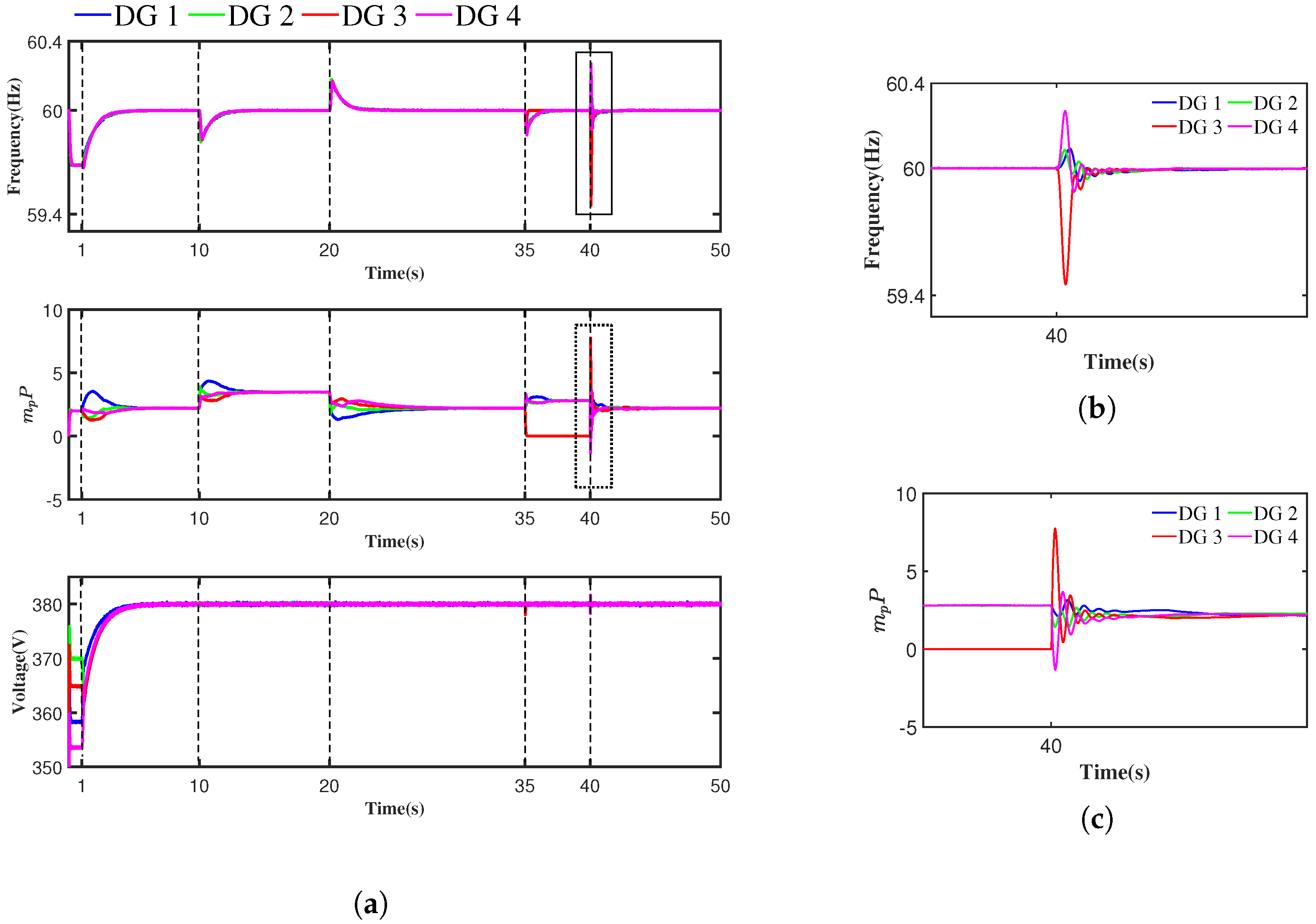
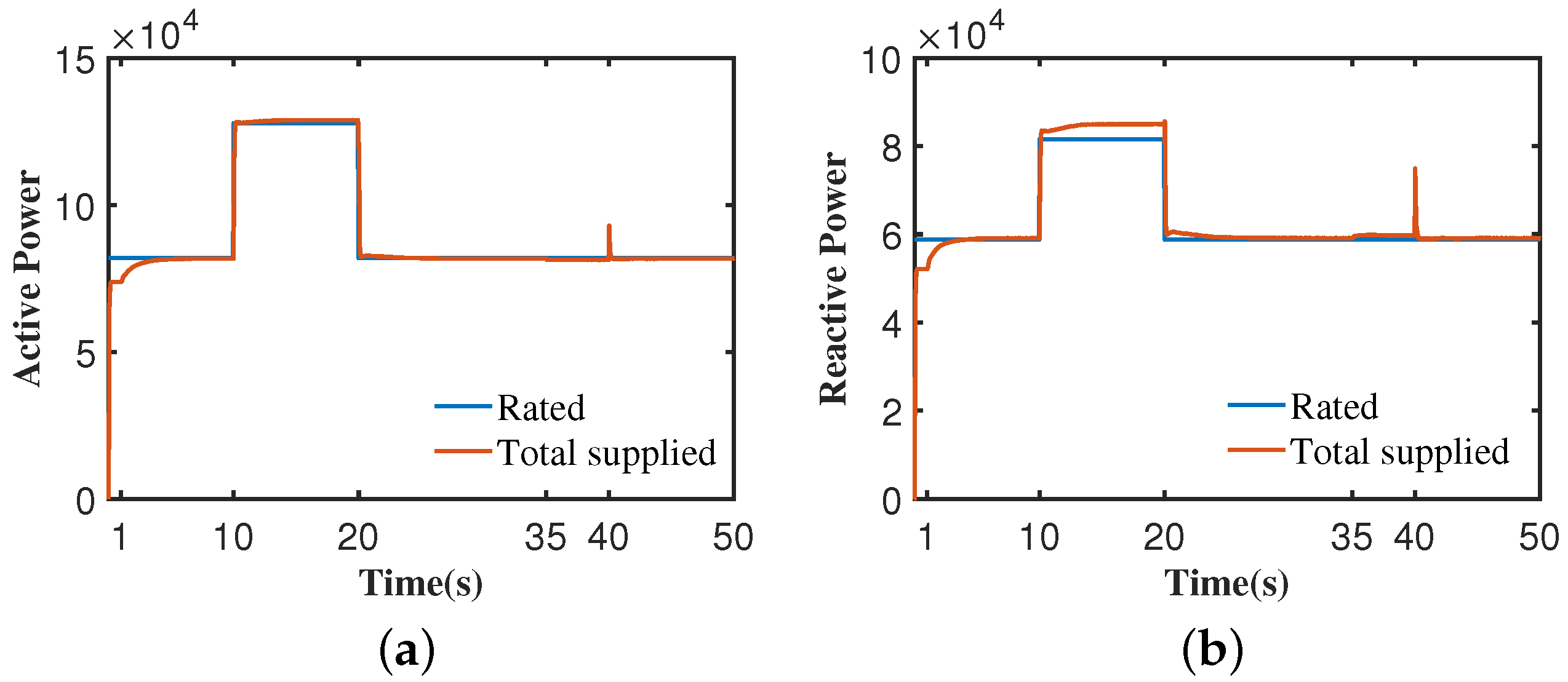
The effectiveness of the proposed distributed DPET secondary control scheme was verified in MATLAB/SimPowerSystems. A 60 Hz/380 V 4-DG test MG system was built. The diagram of communication and electrical topology of the MG is shown in Figure 1. The electric and control parameters are provided in Table 1.

Figure 1.
Diagram of the communication and electrical topology of the MG.

Table 1.
Electric and control parameters of the MG system.
4.1. Case Studies
The MG system operates in islanded mode at s. Initially, only the primary control is activated. The timeline of the study cases is described below.
- Case 1: At s, the secondary control is activated.
- Case 2: At s, load 3 is connected to the MG.
- Case 3: At s, load 3 is disconnected. The communication link between DG 1 and DG 4 fails at s and restores at s.
- Case 4: At s, DG 3 is disconnected from the MG.
- Case 5: At s, DG 3 is connected to the MG.
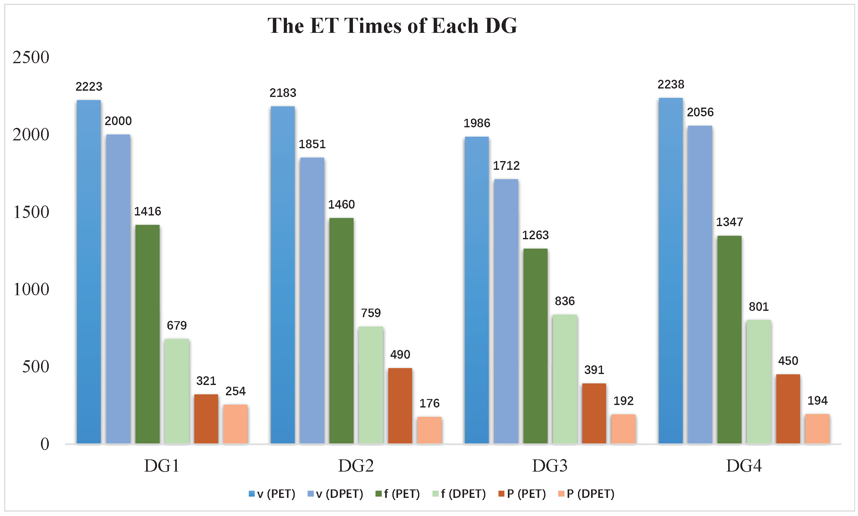
The simulation results of frequency, active power ratio, and voltage under the proposed distributed DPET secondary control scheme are shown in Figure 2. During s, in the absence of secondary control, the system frequency and voltage deviated from and . When the proposed secondary control activated at s, the system frequency and voltage gradually recovered to 60 Hz and 380 V, and the active power ratios reached consensus. Moreover, in Cases 2–5, when load changes, communication-link failures, and plug-and-play events occurred, the system frequency and voltage could still recover to their nominal values while achieving the active power sharing objective. The simulation results of power mismatch between the total supplied and the rated active/reactive power are shown in Figure 3. The power mismatch was under an acceptable range. The controller ET interval of DG 1 is shown in Figure 4, which is usually larger than the evaluating period. Overall, the DPET secondary control scheme proposed in this paper could achieve the secondary control objectives while reducing the communication burden, and the design of dynamic ETCs was reasonable.

Figure 2.
Simulation results of distributed DPET secondary control scheme (the time period of different cases is separated with dashed lines). (a) Frequency, active power ratio, and voltage response curves. (b) Enlarged view of the solid rectangular area on the left. (c) Enlarged view of the dotted rectangular area on the left.

Figure 3.
Power mismatch of active/reactive power. (a) Active power. (b) Reactive power.

Figure 4.
ET interval of the frequency, active power, and voltage controllers of DG 1. (a) Frequency. (b) Active power. (c) Voltage.
4.2. Comparisons
The proposed distributed DPET secondary control scheme is compared with a traditional PET secondary control scheme from the perspective of communication burden. The controller ET times of the above two schemes are shown in Figure 5. Our proposed scheme had fewer ET times than the PET scheme did. The average ET times of frequency, voltage, and active power controllers of the DPET scheme were 768, 1905 and 204, respectively, which were smaller than the 1372, 2158 and 413 of the PET scheme, respectively.

Figure 5.
ET times of frequency, voltage, and active power controllers of each DG under the PET and DPET schemes (for each DG, the blue, green, and orange columns represent the ET times of voltage, frequency, and active power controllers under PET and DPET schemes, respectively).
The advantages of adaptive coefficient are discussed. When a DG is plugged in the system, the system state faces large oscillations that could even lead to system instability. Thus, the plug-in event is considered to compare the control performance of the adaptive and fixed strategies. The frequency controller ET instants and the frequency response curves of the above two methods are shown in Figure 6 and Figure 7, respectively.

Figure 6.
Frequency controller ET instants of each DG. (’x’ represents the ET instant). (a) Fixed . (b) Dynamic .

Figure 7.
Frequency response curves under plug-and-play event. (a) Fixed . (b) Dynamic (comparison experiments were performed with , , , , , , and ).
The total ET times of frequency controllers were reduced from 52 for the fixed to 40 for the adaptive . As shown in Figure 7, under a fixed , the system frequency oscillated from to Hz, which was larger than to Hz under the adaptive . Since the oscillation of the system itself was relatively small, and only DG 1 could adaptively change its , the advantage of adaptive in narrowing the oscillation range is not very obvious, but it did narrow the oscillation amplitude of the system to some extent. As shown in Figure 6, the triggering events of the adaptive were more frequent than those of the fixed , since the adaptive was smaller than at the beginning. Due to the rapid improvement of the system oscillations, the subsequent ET times were reduced, resulting in a decrease in the total ET times and an improvement in control performance.
4.3. Performance under Communication Delay
In this section, the effects of communication delay on our proposed frequency, voltage, and active power controllers are discussed. The communication delay is defined as . Take case 1 in Section 4.1 as an example. Simulation conditions were ms, ms and ms. As shown in Figure 8, with the increase in , the response curves of frequency, voltage, and active power ratios had more oscillations. When was much larger than the evaluating period, for example, ms, the system failed to achieve consensus and became unstable.

Figure 8.
The effect of communication delay on frequency, active power, and voltage controllers.(a) ms. (b) ms. (c) ms.
5. Conclusions
In this paper, a novel distributed DPET secondary control scheme for islanded AC MGs was proposed to achieve the control objectives of frequency or voltage restoration and active power sharing. In our case studies, the ET times of frequency, active power, and voltage controllers in the proposed DPET scheme were reduced by 604, 253 and 209 times, respectively, compared to the traditional PET scheme. Compared with the commonly used fixed coefficient, frequency controllers with an adaptive coefficient reduced the ET times by 12 times. The frequency oscillations in the plug-and-play events were also reduced by about Hz. In general, the proposed DPET secondary control scheme had advantages in reducing the communication burden, and the introduction of adaptive coefficients helps in further reducing the communication burden and improving the control performance. The effectiveness of the proposed DPET secondary control scheme was verified with the simulation results of the MG system under the events of island operation, load changes, link failures, and plug and play.
Author Contributions
B.H.: methodology, writing—original draft, funding acquisition. Y.X.: conceptualization, writing—original draft, methodology. X.J.: validation, supervision. J.F.: validation, supervision. X.L.: investigation. L.D.: investigation. All authors have read and agreed to the published version of the manuscript.
Funding
This research was funded by the National Natural Science Foundation of China under grant 62173256.
Institutional Review Board Statement
Not applicable.
Informed Consent Statement
Not applicable.
Data Availability Statement
Not applicable.
Conflicts of Interest
The authors declare no conflict of interest.
References
- Hatziargyriou, N.; Asano, H.; Iravani, R.; Marnay, C. Microgrids. IEEE Power Energy Mag. 2007, 5, 78–94. [Google Scholar] [CrossRef]
- Razmi, D.; Lu, T. A Literature Review of the Control Challenges of Distributed Energy Resources Based on Microgrids (MGs): Past, Present and Future. Energies 2022, 15, 4676. [Google Scholar] [CrossRef]
- Kim, B.Y.; Oh, K.K.; Moore, K.L.; Ahn, H.S. Distributed coordination and control of multiple photovoltaic generators for power distribution in a microgrid. Automatica 2016, 73, 193–199. [Google Scholar] [CrossRef]
- Bidram, A.; Davoudi, A. Hierarchical Structure of Microgrids Control System. IEEE Trans. Smart Grid 2012, 3, 1963–1976. [Google Scholar] [CrossRef]
- Olfati-Saber, R.; Fax, J.A.; Murray, R.M. Consensus and Cooperation in Networked Multi-Agent Systems. Proc. IEEE 2007, 95, 215–233. [Google Scholar] [CrossRef]
- Bidram, A.; Davoudi, A.; Lewis, F.L.; Guerrero, J.M. Distributed Cooperative Secondary Control of Microgrids Using Feedback Linearization. IEEE Trans. Power Syst. 2013, 28, 3462–3470. [Google Scholar] [CrossRef]
- Bidram, A.; Davoudi, A.; Lewis, F.L.; Qu, Z. Secondary control of microgrids based on distributed cooperative control of multi-agent systems. IET Gener. Transm. Distrib. 2013, 7, 822–831. [Google Scholar] [CrossRef]
- Ullah, S.; Khan, L.; Sami, I.; Ullah, N. Consensus-Based Delay-Tolerant Distributed Secondary Control Strategy for Droop Controlled AC Microgrids. IEEE Access 2021, 9, 6033–6049. [Google Scholar] [CrossRef]
- Lu, X.; Xia, S.; Sun, G.; Hu, J.; Zou, W.; Zhou, Q.; Shahidehpour, M.; Chan, K.W. Hierarchical distributed control approach for multiple on-site DERs coordinated operation in microgrid. Int. J. Electr. Power Energy Syst. 2021, 129, 106864. [Google Scholar] [CrossRef]
- Pullaguram, D.; Rana, R.; Mishra, S.; Senroy, N. Fully distributed hierarchical control strategy for multi-inverter-based AC microgrids. IET Renew. Power Gener. 2020, 14, 2468–2476. [Google Scholar] [CrossRef]
- Nguyen, T.L.; Wang, Y.; Tran, Q.T.; Caire, R.; Xu, Y.; Gavriluta, C. A Distributed Hierarchical Control Framework in Islanded Microgrids and Its Agent-Based Design for Cyber–Physical Implementations. IEEE Trans. Ind. Electron. 2021, 68, 9685–9695. [Google Scholar] [CrossRef]
- Girard, A. Dynamic Triggering Mechanisms for Event-Triggered Control. IEEE Trans. Autom. Control 2015, 60, 1992–1997. [Google Scholar] [CrossRef]
- Ge, X.; Han, Q.L.; Ding, L.; Wang, Y.L.; Zhang, X.M. Dynamic Event-Triggered Distributed Coordination Control and its Applications: A Survey of Trends and Techniques. IEEE Trans. Syst. Man Cybern. Syst. 2020, 50, 3112–3125. [Google Scholar] [CrossRef]
- Dimarogonas, D.V.; Frazzoli, E.; Johansson, K.H. Distributed Event-Triggered Control for Multi-Agent Systems. IEEE Trans. Autom. Control 2012, 57, 1291–1297. [Google Scholar] [CrossRef]
- Yang, C.; Yao, W.; Fang, J.; Ai, X.; Chen, Z.; Wen, J.; He, H. Dynamic event-triggered robust secondary frequency control for islanded AC microgrid. Appl. Energy 2019, 242, 821–836. [Google Scholar] [CrossRef]
- Qian, Y.Y.; Premakumar, A.V.P.; Wan, Y.; Lin, Z.; Shamash, Y.A.; Davoudi, A. Dynamic Event-Triggered Distributed Secondary Control of DC Microgrids. IEEE Trans. Power Electron. 2022, 37, 10226–10238. [Google Scholar] [CrossRef]
- Han, F.; Lao, X.; Li, J.; Wang, M.; Dong, H. Dynamic event-triggered protocol-based distributed secondary control for islanded microgrids. Int. J. Electr. Power Energy Syst. 2022, 137, 107723. [Google Scholar] [CrossRef]
- Heemels, W.P.M.H.; Donkers, M.C.F.; Teel, A.R. Periodic Event-Triggered Control for Linear Systems. IEEE Trans. Autom. Control 2013, 58, 847–861. [Google Scholar] [CrossRef]
- Deng, C.; Che, W.W.; Wu, Z.G. A Dynamic Periodic Event-Triggered Approach to Consensus of Heterogeneous Linear Multiagent Systems with Time-Varying Communication Delays. IEEE Trans. Cybern. 2021, 51, 1812–1821. [Google Scholar] [CrossRef]
- Geng, Y.; Ji, J.; Hu, B. The Output Consensus Problem of DC Microgrids With Dynamic Event-Triggered Control Scheme. Front. Energy Res. 2021, 9, 446. [Google Scholar] [CrossRef]
- Lian, Z.; Deng, C.; Wen, C.; Guo, F.; Lin, P.; Jiang, W. Distributed Event-Triggered Control for Frequency Restoration and Active Power Allocation in Microgrids With Varying Communication Time Delays. IEEE Trans. Ind. Electron. 2021, 68, 8367–8378. [Google Scholar] [CrossRef]
- Barooah, P.; Hespanha, J.P. Graph Effective Resistance and Distributed Control: Spectral Properties and Applications. In Proceedings of the Proceedings of the 45th IEEE Conference on Decision and Control, San Diego, CA, USA, 13–15 December 2006; pp. 3479–3485. [Google Scholar] [CrossRef]
- Li, Z.; Cheng, Z.; Si, J.; Li, S. Distributed Event-Triggered Hierarchical Control to Improve Economic Operation of Hybrid AC/DC Microgrids. IEEE Trans. Power Syst. 2022, 37, 3653–3668. [Google Scholar] [CrossRef]
- Ullah, S.; Khan, L.; Sami, I.; Ro, J.S. Voltage/Frequency Regulation With Optimal Load Dispatch in Microgrids Using SMC Based Distributed Cooperative Control. IEEE Access 2022, 10, 64873–64889. [Google Scholar] [CrossRef]
- Li, Z.; Cheng, Z.; Liang, J.; Si, J.; Dong, L.; Li, S. Distributed Event-Triggered Secondary Control for Economic Dispatch and Frequency Restoration Control of Droop-Controlled AC Microgrids. IEEE Trans. Sustain. Energy 2020, 11, 1938–1950. [Google Scholar] [CrossRef]
- Ullah, S.; Khan, L.; Sami, I.; Hafeez, G.; Albogamy, F.R. A Distributed Hierarchical Control Framework for Economic Dispatch and Frequency Regulation of Autonomous AC Microgrids. Energies 2021, 14, 8408. [Google Scholar] [CrossRef]
Publisher’s Note: MDPI stays neutral with regard to jurisdictional claims in published maps and institutional affiliations. |
© 2022 by the authors. Licensee MDPI, Basel, Switzerland. This article is an open access article distributed under the terms and conditions of the Creative Commons Attribution (CC BY) license (https://creativecommons.org/licenses/by/4.0/).